EP2561744A1 - Saatsensorbaugruppe, Pflanzmaschine damit, und Verfahren - Google Patents
Saatsensorbaugruppe, Pflanzmaschine damit, und Verfahren Download PDFInfo
- Publication number
- EP2561744A1 EP2561744A1 EP12177085A EP12177085A EP2561744A1 EP 2561744 A1 EP2561744 A1 EP 2561744A1 EP 12177085 A EP12177085 A EP 12177085A EP 12177085 A EP12177085 A EP 12177085A EP 2561744 A1 EP2561744 A1 EP 2561744A1
- Authority
- EP
- European Patent Office
- Prior art keywords
- seed
- radiation
- tube
- detecting elements
- planter
- Prior art date
- Legal status (The legal status is an assumption and is not a legal conclusion. Google has not performed a legal analysis and makes no representation as to the accuracy of the status listed.)
- Withdrawn
Links
- 238000000034 method Methods 0.000 title claims abstract 4
- 230000005855 radiation Effects 0.000 claims description 137
- 238000000429 assembly Methods 0.000 claims description 15
- 230000000712 assembly Effects 0.000 claims description 15
- 230000001133 acceleration Effects 0.000 claims description 4
- 230000008878 coupling Effects 0.000 claims description 3
- 238000010168 coupling process Methods 0.000 claims description 3
- 238000005859 coupling reaction Methods 0.000 claims description 3
- 238000000151 deposition Methods 0.000 claims 1
- 239000000428 dust Substances 0.000 description 10
- 238000012545 processing Methods 0.000 description 3
- 238000003491 array Methods 0.000 description 2
- 230000000694 effects Effects 0.000 description 2
- 239000002689 soil Substances 0.000 description 2
- 0 *CCCC[N+]([O-])=O Chemical compound *CCCC[N+]([O-])=O 0.000 description 1
- 230000015556 catabolic process Effects 0.000 description 1
- 238000004891 communication Methods 0.000 description 1
- 238000010276 construction Methods 0.000 description 1
- 238000006731 degradation reaction Methods 0.000 description 1
- 238000005516 engineering process Methods 0.000 description 1
- 238000011156 evaluation Methods 0.000 description 1
- 230000005484 gravity Effects 0.000 description 1
- 239000004519 grease Substances 0.000 description 1
- 230000036039 immunity Effects 0.000 description 1
- 239000000463 material Substances 0.000 description 1
- 238000012986 modification Methods 0.000 description 1
- 230000004048 modification Effects 0.000 description 1
- 238000012544 monitoring process Methods 0.000 description 1
- 230000005693 optoelectronics Effects 0.000 description 1
- 239000000575 pesticide Substances 0.000 description 1
- 230000035945 sensitivity Effects 0.000 description 1
- 238000000926 separation method Methods 0.000 description 1
- 239000000126 substance Substances 0.000 description 1
Images


Classifications
-
- A—HUMAN NECESSITIES
- A01—AGRICULTURE; FORESTRY; ANIMAL HUSBANDRY; HUNTING; TRAPPING; FISHING
- A01C—PLANTING; SOWING; FERTILISING
- A01C7/00—Sowing
- A01C7/08—Broadcast seeders; Seeders depositing seeds in rows
- A01C7/10—Devices for adjusting the seed-box ; Regulation of machines for depositing quantities at intervals
- A01C7/102—Regulating or controlling the seed rate
- A01C7/105—Seed sensors
Definitions
- the invention relates to a seed sensor assembly for detecting the passage of a seed through a seed tube, the seed tube having spaced front and rear walls and spaced side walls, the sensor assembly comprising: a radiation emitter on one side wall of the seed tube; an array of radiation detecting elements along the opposite side wall from the radiation emitter and extending from the front wall to the rear wall of the seed tube; whereby the location of the seed between the front and rear walls of the seed tube is determined by which detecting elements of the array of radiation detecting elements have an interruption in the radiation incident thereon caused by the passage of a seed between the radiation emitter and the array of radiation detecting elements.
- monitors It is well known in the agriculture to use a monitor on planters to monitor the seed at each row unit. When first employed, monitors were used to alert the operator of a plugged row unit or a unit without any seed to avoid continued operation of the planter without actually planting seed. More recently, studies have quantified the importance of accurate seed spacing in producing enhanced crop yields. As a result, monitor technology has advanced in efforts to determine seed spacing. Current monitors use the time interval between seeds to determine skips or multiples of seed. These monitors also predict seed spacing in the furrow based on the timing of seed passing the monitor in the seed tube.
- a paper entitled Opto-electronic Sensor System for Rapid Evaluation of Planter Seed Spacing Uniformity, Transactions of the ASAE 41(1):237-245 describes using the seed trajectory, speed of the planter and timing of seed release events to determine seed spacing.
- the goal of the study was to evaluate a sensor located just above the soil surface at the seed drop zone in measuring the seed location relative to the planter. The sensor was then used to determine seed spacing instead of dropping seed onto a grease belt and manually evaluating seed spacing.
- the sensor had two arrays of 12 pairs of LEDs and photo-transistors to sense and locate the seed along one axis.
- an object of this invention is to provide an improved seed sensor assembly for determining seed count and seed spacing on agricultural planters.
- a seed sensor assembly of the above mentioned type comprises a diffuser to evenly distribute radiation from said radiation emitter and means for aligning the radiation received by the detecting elements so that each element receives radiation traveling across the seed tube substantially parallel to the front and rear walls of the seed tube.
- a sensor system is provided with higher sensitivity to seed counting, reduced errors for skips, doubles (intentional double, triples or unintentional); better dust immunity that enables the sensor to be moved closer to the ground, which is desired for closer to true in ground information; improved capability for higher rate seed monitoring, etc.
- the present invention provides a sensor system that uses the seed location relative to the planter as the seed passes through the seed tube, along with other parameters, to determine the seed spacing in the furrow.
- the sensor system of the present invention uses a sensor that not only counts the seed but determines the position of the seed relative to the seed tube in the direction of travel of the planter. From the position information, a trajectory is determined of the seed falling through the seed tube. Travel speed of the planter and the timing of the seed passing the monitor are other necessary factors in determining the seed trajectory. The trajectory then enables the seed spacing to be predicted with a higher degree of accuracy then is possible with sensors that only determine the interval of time between seed drop events.
- a seed tube assembly for an agricultural machine through which grain passes may comprise a tube having a front wall and a rear wall which are spaced apart along an X-direction and which are joined together by two sidewalls spaced apart along a Y-direction.
- a first sensor assembly may comprise a radiation emitter on one side wall of the tube and a radiation diffuser to produce an even distribution of radiation, an array of radiation detecting elements along the other side wall from the radiation emitter and extending from the front wall to the rear wall of the tube, and means for aligning the radiation received by the detecting elements so that each element receives radiation traveling across the seed tube substantially in the Y-direction.
- Such tube further may comprise a second sensor assembly at substantially the same location along the tube, the second sensor assembly having a radiation emitter and a radiation diffuser to produce an even distribution of radiation on one of the front and rear walls of the tube, an array of radiation detecting elements along the other of the front and rear wall of the tube from the radiation emitter and extending from one side wall to the other side wall of the tube, and means for aligning the radiation received by the detecting elements so that each element receives radiation traveling across the seed tube substantially in the X-direction whereby the radiation received by the arrays of radiation detecting elements of the first and second sensor assemblies forms a grid crossing the seed tube in the X and Y directions.
- a second sensor assembly at substantially the same location along the tube, the second sensor assembly having a radiation emitter and a radiation diffuser to produce an even distribution of radiation on one of the front and rear walls of the tube, an array of radiation detecting elements along the other of the front and rear wall of the tube from the radiation emitter and extending from one side wall to the other side wall of the
- the tube assembly may further comprise a third and fourth sensor assembly mounted to the walls of the tube at a location along the walls spaced from the first and second sensor assembly in the direction of travel of grain through the tube.
- the third sensor assembly having a radiation emitter and a radiation diffuser on one side wall of the seed tube, an array of radiation detecting elements along the other side wall from the radiation emitter and extending from the front wall to the rear wall of the tube, and means for aligning the radiation received by the detecting elements so that each element receives radiation traveling across the seed tube substantially in the Y-direction.
- the fourth sensor assembly having a radiation emitter and a radiation diffuser on one of the front and rear walls of the tube, an array of radiation detecting elements along the other of the front and rear wall of the tube from the radiation emitter and extending from one side wall to the other side wall of the tube, and means for aligning the radiation received by the detecting elements so that each element receives radiation traveling across the seed tube substantially in the X-direction.
- Other parameters that further improve the accuracy of determining the seed spacing include acceleration of the planter row unit and the down force applied to the row unit.
- the acceleration of the row unit effects the initial direction of travel of the seed as the seed is released from the meter.
- the down force on the row unit effects the location of the seed tube exit relative to the furrow.
- FIG. 1 is a side view of a planting unit 10 equipped with the sensor system described herein.
- the planting unit 10 is mounted to rectangular toolbar 12 by U-bolts 14.
- the planting unit 10 is provided with a frame 16 having a parallelogram linkage 18 for coupling the planting unit 10 to the toolbar 12 to allow up and down relative movement between the unit 10 and toolbar 12.
- Seed is stored in seed hopper 20 and provided to seed meter 22. From the seed meter 22 the seed is dropped through the seed tube 24 into a planting furrow formed in the soil by furrow openers 26.
- Gauge wheels 28 control the depth of the furrow and closing wheels 29 close the furrow over the seed.
- the gauge wheels 28 are mounted to the frame 16 by arms 31.
- a down force sensor 33 is coupled to one arm 31 and includes a strain gage for measuring the amount of force applied to the gauge wheel by the ground.
- An accelerometer 35 is mounted to the frame 16 and can be placed at any convenient location thereon.
- the toolbar and planting unit are designed to be move over the ground in a forward working direction X identified by the arrow 27.
- Pesticides can be stored in a chemical hopper 30 which is mounted to the planting unit frame 16. This particular planting unit is provided at the front with a row cleaner attachment 34.
- a mechanical down force generator 48 is attached to the toolbar 12 and includes springs 50 to generate a down force applied to the linkage 18.
- the particular down force generator 48 shown is adjustable. Any type of down force generator can be used, fixed force, adjustable force, mechanical, hydraulic, pneumatic, etc.
- the planting unit 10 is shown as an example of the environment in which the present invention is used. The present invention can be used in any of a variety of planting units.
- the seed tube 24, shown in Figs. 1 and 2 is provided with a curved forward wall 36, a curved rear wall 38 and two sidewalls 40 joining the front and rear walls 36 and 38.
- the forward and rear walls are curved rearwardly and downwardly.
- the tube has an open top 42 and an open bottom 44.
- the exterior of front wall is also provided with tangs 45 for mounting the seed tube to the planting unit frame 16.
- seed tube 24 is equipped with a first sensor assembly 56 mounted to the side walls 40 of the seed tube at apertures therein.
- the sensor assembly 56 includes a radiation emitter 58, shown as an array of light emitting diodes (LEDs) 60 on one side wall 40 of the seed tube.
- the LEDs are mounted to a PC board 62 with conductive strips forming electrical connections with the LEDs 60 mounted thereon.
- a lens 64 Positioned in front of the LEDs and preferably flush with the inner edge of the seed tube side wall is a lens 64 which directs the light emitted by the LEDs into parallel beams substantially in the Y-direction as shown by the arrows 66.
- One type of lens can be a privacy filter such as that made by the 3M Company and of the type described in US Patent No. 6,398,370 . Any number of LEDs can be used in the emitter 58 as long as the emitters and lens 64, in combination, produce beams of radiation in the Y direction across substantially the entire width of the side wall 40.
- the sensor assembly 56 further includes a radiation detector 68 mounted to the opposite side wall 40 of the seed tube.
- a lens 69 is flush with the inside surface of the seed tube side wall 40 and will transmit radiation substantially in the Y-direction as shown by arrows 70.
- Radiation detecting elements 72a-g are arranged in an array 76. Elements 72 can be photo-diodes or photo-transistors or other detector capable of detecting the radiation from the radiation emitter 58.
- the detecting elements 72 are also mounted on a PC board 78 with conductive strips forming electrical connections.
- the lens 69 ensures that radiation received by the radiation detecting elements 72 are traveling substantially in the Y-direction. Radiation not traveling in the Y-direction, such as shown by arrow 74, is blocked or reflected by the lens 69.
- Each of the detecting elements 72 are separated from one another by divider walls 80 extending between the lens 69 and the detector elements 72. The divider walls further help to ensure that the detecting elements 72 receive radiation traveling substantially in the Y-direction.
- a second sensor assembly 90 is mounted to the seed tube front and rear walls 36, 38.
- the second sensor assembly 90 is of substantially the same construction as the first sensor assembly 56.
- Second sensor assembly 90 includes a radiation emitter 92 mounted to the front wall 36 of the seed tube 24.
- the emitter 92 is in the form of an array 94 of LEDs 96 mounted to a PC board 98. LEDs 96 are covered by a lens 100 to direct radiation in substantially the X-direction.
- the lens 100 is flush with the interior surface of the front wall 36.
- Sensor assembly 90 further includes a radiation detector 102 in the form of an array 103 of radiation detecting elements 104a-d on the rear wall 38, opposite the radiation emitter 92.
- the detecting elements 104a-d are similarly mounted on a PC board 106 with conductive strips forming electrical connections.
- the detecting elements are positioned behind a lens 108 that limits radiation passing therethrough to travel in substantially the X-direction as shown by the arrows 112.
- Each of the detecting elements 104 are separated from one another by divider walls 110 extending between the lens 108 and the detector elements 104.
- the divider walls further help to ensure that the detecting elements 72 receive radiation traveling in the X-direction. While the radiation emitter 92 is shown mounted on the front wall of the seed tube and the detector 102 is shown mounted on the rear wall, they can be reversed without effecting the functioning of the second sensor assembly 90.
- the second sensor assembly provides the location in the Y-direction of the seed passing through the tube.
- the second sensor assembly 90 is positioned to sense along the same plane as the first sensor assembly 56.
- the two sensor assemblies 56, 90 can be located in different planes and the difference accounted for in the processing algorithm.
- the first and second sensor assemblies 56, 90 cooperate to divide the interior passage of the seed tube into a grid.
- the X and Y position of the seed is determined.
- multiples of seed can be readily detected. For example, in Fig. 4 seeds 114 and 116 are both being sensed by the same radiation detecting element 72c of the detector 68 and therefore assigned the same location in the X direction. With only the first sensor assembly 56, seeds 114, 116 would be counted as a single seed.
- both sensor assemblies 56 and 90, the X and Y positions of the seeds is determined and both radiation detectors 104b and 104d will detect a seed, indicating two seeds, not one passing the sensors.
- the use of two sensors thus provides improved precision in counting seeds.
- the seed 82 when the seed 82 falls through the seed tube, it blocks a significant portion, approximately one half, of the radiation flowing across the seed tube and into the detector 72e.
- the portion of the normal radiation that is blocked with the sensor assembly 56 is much greater than the portion of radiation blocked in a conventional sensor that receives radiation across the entire width of the seed tube.
- the signal to noise ratio is much greater with the sensors in the present invention compared to prior sensors.
- This increased signal to noise ratio enables the sensor assemblies to better distinguish between seeds and dust.
- the sensor assembly allows the sensor assembly to be located closer to the seed tube outlet compared to other currently available seed sensors where there is more dust. The closer proximity to the furrow allows greater precision in determining seed spacing.
- Fig. 5a shows the signal 202 generated by dust in the seed tube.
- Fig. 5b shows the passing of a seed and the peak 204 in the signal generated by the seed.
- the peak 204 is relatively small from the dust signal 202 and can be easily missed by the signal processing algorithm.
- Figs. 6a and 6b show the signals from three of the radiation detectors 72.
- Fig, 6a shows the signals 206, 208 and 210 generated by dust. This represents background noise.
- Fig. 6b shows the peaks 212, 214, 216 generated by seeds passing the detectors. Since the seed blocks a larger percentage of the radiation incident upon the detectors, the seed generated peaks in the signal are much larger than the baseline dust noise and are easier to distinguish from the noise.
- Figure 7 shows a single seed passing solely by detectors 72c and 104b. Peaks 218 and 220 are generated in the detector signals while the other detectors, 72a and B and 104a have no peaks in their signals.
- Fig. 8 shows two seeds passing through the sensor assemblies. One seed is sensed solely by detectors 72a and 104a generating peaks 222 and 224 in their output signals. The other seed is sensed by detectors 72c and 104b, generating peaks 226 and 228 in their output signals.
- Figure 9 shows one seed passing partially in front of adjacent detectors 72b and 72c but not in front of detector 72a.
- the signal from 72a continues to register the background noise.
- Signals from 72b and 72c have peaks 230 and 232 representing the seed but they are less then the peaks of Fig, 6b where the seed is sensed entirely by one detector.
- Fig. 10 is similar to Fig. 9 with one seed passing partial in front of detectors 72b and 72c but with another seed is passing in front of detector 72a, generating the peak 234.
- Fig. 11a shows one seed partially passing both the detectors 104a and 104b. Like Fig. 9 , shorter peaks 236 and 238 are generated. Figure 11b in turn shows two seeds simultaneously passing the detectors 104a and 104b. As a result of the two seeds, the peaks 240 and 242 generated are larger than the single seed peaks of Fig. 11a .
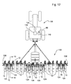
- a Tractor 120 is shown towing a planter 122.
- the planter includes a toolbar 12 having a plurality of planting units 10 attached thereto.
- a number of support wheel and tire assemblies 124 are coupled to the toolbar for supporting the planter.
- Wheel and tire assemblies 124 are movable relative to the toolbar to raise and lower the toolbar between a working position in which the planter row units engage the ground and a raised transport position for moving the planter without engaging the ground.
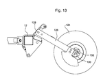
- Pivot arms 126 ( Fig. 13 ) carry the wheel and tire assemblies 124 and are in turn coupled to a pivot 128 mounted to the toolbar.
- a rotation sensor 130 at the hub 132 of one wheel and tire assembly is used to determine the speed of travel of the planter through a field.
- the tractor 120 is equipped with GPS receiver 134 and processor 136 from which the location, as well as the direction and speed of travel of the tractor and planter, can be determined.
- speed sensors such as radar sensors 138 mounted to the toolbar can be used to determine the planter speed. Sensors 138 determine the speed by sensing the ground passing beneath the toolbar. While one sensor 138 is sufficient to determine the planter speed, having two sensors spaced apart along the length of the toolbar enables the speed of individual planter units 10 to be determined as the planter follows a contour path. Due to the curved path of the contour, the outside planter row unit moves at a faster speed than the inside planter row unit. Thus, the two sensors 138 are spaced as far apart as practical for greater precision in determining speed differences on a contour. Other types of speed sensors can be used as well.
- a planter monitor 140 in the tractor has a processor 86 that receives input signals from the seed tube sensor assemblies56 and 90 as well as input signals from the speed sensor or sensors.
- a seed trajectory can be predicted based on the release point of the seed in the meter and the X location of the seed as it passes the sensor assembly 56. The trajectory, the height of the sensor assembly relative to the furrow and the ground speed of the planter unit are used to predict the seed spacing in the furrow. At a minimum, only the first sensor assembly 56 is needed to determine the X direction location of the seed and to predict the seed spacing.
- the use of the second sensor assembly 90 to determine the location in the Y direction can provide more accuracy to the seed spacing as it can better detect multiple seeds and predict bouncing of the seed caused by contact with the seed tube side walls 40.
- Determination of the seed trajectory can be made with even more precision with the use of two sets of sensor assemblies 56, 90 and 56', 90' as shown in Fig. 14 .
- sensor assemblies 56. 90 are vertically spaced above sensor assemblies 56', 90'.
- the X and Y positions of seeds are determined at two locations along the length of the seed tube. Having X and Y location data at two points along the seed tube enables greater precision in determining the seed trajectory and thus the final seed spacing in the furrow.
- Sensor 200 is shown in a seed tube 202.
- the sensor 200 includes a radiation emitter 204, shown as an array of light emitting diodes (LEDs) 206 on one wall 208 of the seed tube.
- the LEDs are mounted to a PC board 210 with conductive strips forming electrical connections with the LEDs 206 mounted thereon.
- the sensor further has a radiation detector 218 consisting of an array of detecting elements 220(a-g) on the opposite side of the seed tube from the transmitters 206.
- the detecting elements can be photo-diodes or photo-transistors or other detector capable of detecting the level of radiation from the emitter 204.
- the detecting elements 220 are also mounted on a PC board 222 with conductive strips forming electrical connections.
- a diffuser 212 Positioned in front of the emitter 204 and preferably flush with the inner edge of the seed tube side wall is a diffuser 212.
- the diffuser 212 ensures that the radiation, e.g. light from the LEDs, has a uniform intensity across the width of the array of emitters. Having a uniform light intensity provides improved accuracy to the sensor as all detecting elements 220 receive the same amount of radiation when there are no seeds in the seed tube passing the sensor 200.
- any number of LEDs 206 can be used in the radiation emitter 204 as long as a uniform intensity of light is produced across the seed tube.
- lens 224 Positioned in front of the detecting elements 220 is a lens 224 which directs the light emitted by the LEDs into parallel beams substantially in the Y-direction as shown by the arrows 226.
- lens can be a privacy filter such as that made by the 3M Company and of the type described in US Patent No. 6,398,370 .
- the detecting elements 220 are also set back from the seed tube and separated by from one another by dividing walls 228.
- the dividing walls 228 help to further prevent any radiation incident on the detecting elements that is not aligned in the Y-direction.
- the dividing walls 228 are optional.
- the lens 224 can be spaced from the detecting elements as shown in Fig. 15 or placed immediately before the detecting elements. While only a single lens 224 is shown on the side of the seed tube as the detecting elements, another lens to align the radiation in the Y-direction can be placed adjacent the diffuser 212 on the emitter side of the tube.
- a second sensor 200 can be placed in the other walls of the seed tube to determine both the X and Y location of the seed in the tube. Sensors 200 differ from those described above in the addition of a radiation diffuser 212 to produce uniform intensity of radiation across the sensor.
- the above sensors are “transmissive” sensors in the sense that they "transmit” radiation across the seed tube.
- a reflective sensor is needed to detect seeds.
- Such an instance is when seed movement in the seed tube is not be gravity or air but by a mechanical structure such as the brush belt shown in US Patent Publication US2010/0192819 A1 .
- There the seed is held in the bristles of a brush which prevents light from shining across the seed tube.
- a reflective sensor 300 is shown in Figs. 16-17 to detect seeds traveling in the brush belt.
- the belt 302 has a base member 304 and a plurality of bristles 306.
- the belt operates in a housing having a wall 308.
- the sensor 300 is mounted in an opening in the housing wall 308 and includes a window 310 that fits in the opening in the wall 308 and through which radiation from and to the sensor passes.
- the sensor 300 includes an emitter 312 mounted to a PC board 314 and electrically connected thereto. Radiation from the emitter is shown by the arrows 316 which is directed through a diffuser 318 that uniformly distributes the radiation to and through the window 310. Radiation impinges on and is reflected by the seed 320. Reflected radiation passes through lens 322 such as the 3M film mentioned above. The lens 322 aligns the radiation so that the radiation is perpendicular to the plane of the lens 322. After passing the filter, the radiation is detected by one of several detecting elements 324 of an array of detecting elements 324 mounted on a PC board 326.
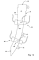
- Fig. 17 is a view looking into the sensor 300 from the line 17-17 of fig. 16 .
- the sensor as shown has a total of four detecting elements 324 arranged in the array.
- the detecting elements 324 can be separated by dividing walls 328. Again, the dividing walls are optional.
- the emitter and the detecting elements are arranged at an angle 330 relative to one another. This angle 330 may be as small as 3 - 5 degrees and is shown exaggerated in Fig. 16 . The angle 330 may be larger than 5 degrees if desired.
- sensors While the sensors have been shown and described as fitting into openings in the seed tubes, they may be placed on the outside of the tubes with the tubes, or a portion of the tubes, made of a material that is transparent or substantially transparent to the radiation. Such a tube and sensor combination is shown in US patent 7,472,660 .
- the invention has been described in the context of a generally vertically oriented seed tube having front, rear and side walls.
- the designation of the walls as front, rear and side is only for convenience in describing the invention.
- the sensor assemblies can be used in a horizontal seed tube as well and an inclined seed tube.
- the labels front, rear and side applied to the walls shall be construed solely as a means of distinguishing between walls without regard to the actual orientation of the walls in physical space.
Landscapes
- Life Sciences & Earth Sciences (AREA)
- Soil Sciences (AREA)
- Environmental Sciences (AREA)
- Sowing (AREA)
Applications Claiming Priority (1)
| Application Number | Priority Date | Filing Date | Title |
|---|---|---|---|
| US13/218,000 US8618465B2 (en) | 2008-11-13 | 2011-08-25 | Seed sensor system and method for improved seed count and seed spacing |
Publications (1)
| Publication Number | Publication Date |
|---|---|
| EP2561744A1 true EP2561744A1 (de) | 2013-02-27 |
Family
ID=46826224
Family Applications (1)
| Application Number | Title | Priority Date | Filing Date |
|---|---|---|---|
| EP12177085A Withdrawn EP2561744A1 (de) | 2011-08-25 | 2012-07-19 | Saatsensorbaugruppe, Pflanzmaschine damit, und Verfahren |
Country Status (7)
| Country | Link |
|---|---|
| EP (1) | EP2561744A1 (de) |
| AR (1) | AR087652A1 (de) |
| AU (1) | AU2012216315A1 (de) |
| BR (1) | BR102012018113A2 (de) |
| CA (1) | CA2786376C (de) |
| MX (1) | MX2012009151A (de) |
| RU (1) | RU2012134216A (de) |
Cited By (6)
| Publication number | Priority date | Publication date | Assignee | Title |
|---|---|---|---|---|
| WO2015058273A1 (pt) * | 2013-10-23 | 2015-04-30 | Assy José Roberto Do Amaral | Processo e dispositivo para controle de falhas na dosagem de sementes em plantadeiras |
| EP2901837A1 (de) * | 2014-01-31 | 2015-08-05 | Deere & Company | Saatübergabesystem |
| NL2014421A (nl) * | 2014-03-10 | 2016-01-20 | Grimme Landmaschinenfabrik Gmbh & Co Kg | Werkwijze en inrichting voor de detectie van de scheiding van aardappelknollen in plantmachines evenals aan de transportband ervan aangebrachte meenemers. |
| EP3135090A1 (de) * | 2015-08-24 | 2017-03-01 | Digitroll Kft. | Samensensor und verfahren zur erfassung der blockierung eines säkanals |
| GB2546864A (en) * | 2016-01-08 | 2017-08-02 | Deere & Co | Systems for monitoring seeds and methods therof |
| US12050169B2 (en) | 2019-03-22 | 2024-07-30 | Precision Planting Llc | Particle counting apparatus, systems and methods |
Families Citing this family (1)
| Publication number | Priority date | Publication date | Assignee | Title |
|---|---|---|---|---|
| WO2018144553A1 (en) * | 2017-01-31 | 2018-08-09 | Kinze Manufacturing, Inc. | Radar based seed sensor for use with agricultural systems, methods, and apparatus |
Citations (8)
| Publication number | Priority date | Publication date | Assignee | Title |
|---|---|---|---|---|
| US6192813B1 (en) * | 1999-05-21 | 2001-02-27 | Flexi-Coil Ltd. | Apparatus for controlling the flow rate of an air seeder |
| US6398370B1 (en) | 2000-11-15 | 2002-06-04 | 3M Innovative Properties Company | Light control device |
| EP1662247A1 (de) * | 2004-11-24 | 2006-05-31 | Amazonen-Werke H. Dreyer GmbH & Co. KG | Verfahren zur Bestimmung der Partikelform und/oder Grösse von landwirtschaftlichen Gutpartikeln |
| EP1772048A1 (de) * | 2005-10-10 | 2007-04-11 | Amazonen-Werke H. Dreyer GmbH & Co. KG | Vorrichtung zum optischen Zählen kleiner Körperchen |
| US7472660B2 (en) | 2005-10-13 | 2009-01-06 | Deere & Company | Seed tube for an agricultural seeding machine |
| US20100116974A1 (en) * | 2008-11-13 | 2010-05-13 | Liu James Z | Seed Sensor System And Method For Improved Seed Count And Seed Spacing |
| US20100192819A1 (en) | 2009-02-02 | 2010-08-05 | Elijah Garner | Seeding Machine With Seed Delivery System |
| US20100264163A1 (en) * | 2008-11-13 | 2010-10-21 | Tevs Nikolai R | Product Dispensing Apparatus And Method |
-
2012
- 2012-07-19 EP EP12177085A patent/EP2561744A1/de not_active Withdrawn
- 2012-07-20 BR BR102012018113A patent/BR102012018113A2/pt not_active Application Discontinuation
- 2012-08-08 MX MX2012009151A patent/MX2012009151A/es not_active Application Discontinuation
- 2012-08-09 RU RU2012134216/13A patent/RU2012134216A/ru not_active Application Discontinuation
- 2012-08-15 CA CA2786376A patent/CA2786376C/en active Active
- 2012-08-20 AU AU2012216315A patent/AU2012216315A1/en not_active Abandoned
- 2012-08-23 AR ARP120103111A patent/AR087652A1/es unknown
Patent Citations (8)
| Publication number | Priority date | Publication date | Assignee | Title |
|---|---|---|---|---|
| US6192813B1 (en) * | 1999-05-21 | 2001-02-27 | Flexi-Coil Ltd. | Apparatus for controlling the flow rate of an air seeder |
| US6398370B1 (en) | 2000-11-15 | 2002-06-04 | 3M Innovative Properties Company | Light control device |
| EP1662247A1 (de) * | 2004-11-24 | 2006-05-31 | Amazonen-Werke H. Dreyer GmbH & Co. KG | Verfahren zur Bestimmung der Partikelform und/oder Grösse von landwirtschaftlichen Gutpartikeln |
| EP1772048A1 (de) * | 2005-10-10 | 2007-04-11 | Amazonen-Werke H. Dreyer GmbH & Co. KG | Vorrichtung zum optischen Zählen kleiner Körperchen |
| US7472660B2 (en) | 2005-10-13 | 2009-01-06 | Deere & Company | Seed tube for an agricultural seeding machine |
| US20100116974A1 (en) * | 2008-11-13 | 2010-05-13 | Liu James Z | Seed Sensor System And Method For Improved Seed Count And Seed Spacing |
| US20100264163A1 (en) * | 2008-11-13 | 2010-10-21 | Tevs Nikolai R | Product Dispensing Apparatus And Method |
| US20100192819A1 (en) | 2009-02-02 | 2010-08-05 | Elijah Garner | Seeding Machine With Seed Delivery System |
Non-Patent Citations (1)
| Title |
|---|
| "Opto-electronic Sensor System for Rapid Evaluation of Planter Seed Spacing Uniformity", TRANSACTIONS OF THE ASAE, vol. 41, no. 1, pages 237 - 245 |
Cited By (16)
| Publication number | Priority date | Publication date | Assignee | Title |
|---|---|---|---|---|
| US9999173B2 (en) | 2013-10-23 | 2018-06-19 | Jose Roberto DO AMARAL ASSY | Method and device for avoiding seed-metering errors in planters |
| US10405484B2 (en) | 2013-10-23 | 2019-09-10 | José Roberto do Amaral Assy | Method and device for avoiding seed-metering errors in planters |
| WO2015058273A1 (pt) * | 2013-10-23 | 2015-04-30 | Assy José Roberto Do Amaral | Processo e dispositivo para controle de falhas na dosagem de sementes em plantadeiras |
| EP2901837A1 (de) * | 2014-01-31 | 2015-08-05 | Deere & Company | Saatübergabesystem |
| US9345189B2 (en) | 2014-01-31 | 2016-05-24 | Deere & Company | Sensor and sensor mount assembly for seed delivery system |
| BE1022738B1 (de) * | 2014-03-10 | 2016-08-25 | Grimme Landmaschinenfabrik Gmbh & Co. Kg | Verfahren und Vorrichtung zur Erfassung der Vereinzelung von Kartoffelknollen in Legemaschinen sowie an deren Förderer vorgesehener Mitnehmer |
| NL2014421A (nl) * | 2014-03-10 | 2016-01-20 | Grimme Landmaschinenfabrik Gmbh & Co Kg | Werkwijze en inrichting voor de detectie van de scheiding van aardappelknollen in plantmachines evenals aan de transportband ervan aangebrachte meenemers. |
| WO2017033034A1 (en) * | 2015-08-24 | 2017-03-02 | Digitroll Kft. | Seed counting sensor and method for detecting blockage of a seed conveying pipe |
| EP3135090A1 (de) * | 2015-08-24 | 2017-03-01 | Digitroll Kft. | Samensensor und verfahren zur erfassung der blockierung eines säkanals |
| CN108347880A (zh) * | 2015-08-24 | 2018-07-31 | 帝基特罗有限公司 | 种子计数传感器和用于检测种子输送管道的堵塞的方法 |
| RU2709327C2 (ru) * | 2015-08-24 | 2019-12-17 | Диджитролл Кфт. | Датчик счета семян и способ обнаружения засорения семяподающей трубы |
| AU2016313367B2 (en) * | 2015-08-24 | 2020-06-25 | Digitroll Kft. | Seed counting sensor and method for detecting blockage of a seed conveying pipe |
| CN108347880B (zh) * | 2015-08-24 | 2021-03-23 | 帝基特罗有限公司 | 种子计数传感器和用于检测种子输送管道的堵塞的方法 |
| GB2546864A (en) * | 2016-01-08 | 2017-08-02 | Deere & Co | Systems for monitoring seeds and methods therof |
| GB2546864B (en) * | 2016-01-08 | 2021-10-06 | Deere & Co | Systems for monitoring seeds and methods therof |
| US12050169B2 (en) | 2019-03-22 | 2024-07-30 | Precision Planting Llc | Particle counting apparatus, systems and methods |
Also Published As
| Publication number | Publication date |
|---|---|
| CA2786376C (en) | 2019-09-24 |
| AU2012216315A1 (en) | 2013-03-14 |
| CA2786376A1 (en) | 2013-02-25 |
| RU2012134216A (ru) | 2014-02-20 |
| BR102012018113A2 (pt) | 2016-08-23 |
| AR087652A1 (es) | 2014-04-09 |
| MX2012009151A (es) | 2013-02-25 |
Similar Documents
| Publication | Publication Date | Title |
|---|---|---|
| US8618465B2 (en) | Seed sensor system and method for improved seed count and seed spacing | |
| US20100116974A1 (en) | Seed Sensor System And Method For Improved Seed Count And Seed Spacing | |
| CA2786376C (en) | Seed sensor system and method for improved seed count and seed spacing | |
| US9807923B2 (en) | Seed characteristic sensor | |
| EP2409558B1 (de) | Produktausgabevorrichtung und Steuerverfahren dafür | |
| ES2956416T3 (es) | Aparato, sistemas y métodos de recuento de partículas | |
| AU2010200307B2 (en) | Seed delivery apparatus with sensor and moving member to capture and move seed to a lower outlet opening | |
| EP3510852B1 (de) | Verfahren zur abbildung der reihengeschwindigkeiten einer sämaschine | |
| ES2627181T5 (es) | Sistema y método de monitorización de plantadora | |
| Lan et al. | Opto-electronic sensor system for laboratory measurement of planter seed spacing with small seeds | |
| US8669514B2 (en) | Arrangement of sensors in a seed counting apparatus for a planter monitor | |
| EP2888614B1 (de) | Saatsensor mit lichtrohr-fotodetektoranordnung | |
| Hajahmed et al. | Development of an opto-electronic monitoring system for crop planter seed metering unit |
Legal Events
| Date | Code | Title | Description |
|---|---|---|---|
| PUAI | Public reference made under article 153(3) epc to a published international application that has entered the european phase |
Free format text: ORIGINAL CODE: 0009012 |
|
| AK | Designated contracting states |
Kind code of ref document: A1 Designated state(s): AL AT BE BG CH CY CZ DE DK EE ES FI FR GB GR HR HU IE IS IT LI LT LU LV MC MK MT NL NO PL PT RO RS SE SI SK SM TR |
|
| AX | Request for extension of the european patent |
Extension state: BA ME |
|
| STAA | Information on the status of an ep patent application or granted ep patent |
Free format text: STATUS: THE APPLICATION HAS BEEN WITHDRAWN |
|
| 18W | Application withdrawn |
Effective date: 20130814 |