EP2561820B1 - Dispositif d'application de fluide sans contact - Google Patents
Dispositif d'application de fluide sans contact Download PDFInfo
- Publication number
- EP2561820B1 EP2561820B1 EP11006973.9A EP11006973A EP2561820B1 EP 2561820 B1 EP2561820 B1 EP 2561820B1 EP 11006973 A EP11006973 A EP 11006973A EP 2561820 B1 EP2561820 B1 EP 2561820B1
- Authority
- EP
- European Patent Office
- Prior art keywords
- fluid
- application
- reservoir
- application head
- application device
- Prior art date
- Legal status (The legal status is an assumption and is not a legal conclusion. Google has not performed a legal analysis and makes no representation as to the accuracy of the status listed.)
- Active
Links
Images













Classifications
-
- B—PERFORMING OPERATIONS; TRANSPORTING
- B65—CONVEYING; PACKING; STORING; HANDLING THIN OR FILAMENTARY MATERIAL
- B65D—CONTAINERS FOR STORAGE OR TRANSPORT OF ARTICLES OR MATERIALS, e.g. BAGS, BARRELS, BOTTLES, BOXES, CANS, CARTONS, CRATES, DRUMS, JARS, TANKS, HOPPERS, FORWARDING CONTAINERS; ACCESSORIES, CLOSURES, OR FITTINGS THEREFOR; PACKAGING ELEMENTS; PACKAGES
- B65D83/00—Containers or packages with special means for dispensing contents
- B65D83/14—Containers for dispensing liquid or semi-liquid contents by internal gaseous pressure, i.e. aerosol containers comprising propellant
- B65D83/16—Actuating means
- B65D83/26—Actuating means operating automatically, e.g. periodically
-
- A—HUMAN NECESSITIES
- A47—FURNITURE; DOMESTIC ARTICLES OR APPLIANCES; COFFEE MILLS; SPICE MILLS; SUCTION CLEANERS IN GENERAL
- A47K—SANITARY EQUIPMENT; ACCESSORIES THEREFOR, e.g. TOILET ACCESSORIES
- A47K5/00—Holders or dispensers for soap, toothpaste or the like
- A47K5/06—Dispensers for soap
- A47K5/12—Dispensers for soap for liquid or pasty soap
-
- A—HUMAN NECESSITIES
- A47—FURNITURE; DOMESTIC ARTICLES OR APPLIANCES; COFFEE MILLS; SPICE MILLS; SUCTION CLEANERS IN GENERAL
- A47K—SANITARY EQUIPMENT; ACCESSORIES THEREFOR, e.g. TOILET ACCESSORIES
- A47K5/00—Holders or dispensers for soap, toothpaste or the like
- A47K5/06—Dispensers for soap
- A47K5/12—Dispensers for soap for liquid or pasty soap
- A47K5/1217—Electrical control means for the dispensing mechanism
-
- A—HUMAN NECESSITIES
- A61—MEDICAL OR VETERINARY SCIENCE; HYGIENE
- A61B—DIAGNOSIS; SURGERY; IDENTIFICATION
- A61B90/00—Instruments, implements or accessories specially adapted for surgery or diagnosis and not covered by any of the groups A61B1/00 - A61B50/00, e.g. for luxation treatment or for protecting wound edges
- A61B90/80—Implements for cleaning or washing the skin of surgeons or patients
-
- B—PERFORMING OPERATIONS; TRANSPORTING
- B05—SPRAYING OR ATOMISING IN GENERAL; APPLYING FLUENT MATERIALS TO SURFACES, IN GENERAL
- B05B—SPRAYING APPARATUS; ATOMISING APPARATUS; NOZZLES
- B05B12/00—Arrangements for controlling delivery; Arrangements for controlling the spray area
- B05B12/08—Arrangements for controlling delivery; Arrangements for controlling the spray area responsive to condition of liquid or other fluent material to be discharged, of ambient medium or of target ; responsive to condition of spray devices or of supply means, e.g. pipes, pumps or their drive means
- B05B12/12—Arrangements for controlling delivery; Arrangements for controlling the spray area responsive to condition of liquid or other fluent material to be discharged, of ambient medium or of target ; responsive to condition of spray devices or of supply means, e.g. pipes, pumps or their drive means responsive to conditions of ambient medium or target, e.g. humidity, temperature position or movement of the target relative to the spray apparatus
- B05B12/122—Arrangements for controlling delivery; Arrangements for controlling the spray area responsive to condition of liquid or other fluent material to be discharged, of ambient medium or of target ; responsive to condition of spray devices or of supply means, e.g. pipes, pumps or their drive means responsive to conditions of ambient medium or target, e.g. humidity, temperature position or movement of the target relative to the spray apparatus responsive to presence or shape of target
-
- B—PERFORMING OPERATIONS; TRANSPORTING
- B05—SPRAYING OR ATOMISING IN GENERAL; APPLYING FLUENT MATERIALS TO SURFACES, IN GENERAL
- B05B—SPRAYING APPARATUS; ATOMISING APPARATUS; NOZZLES
- B05B9/00—Spraying apparatus for discharge of liquids or other fluent material, without essentially mixing with gas or vapour
- B05B9/03—Spraying apparatus for discharge of liquids or other fluent material, without essentially mixing with gas or vapour characterised by means for supplying liquid or other fluent material
- B05B9/04—Spraying apparatus for discharge of liquids or other fluent material, without essentially mixing with gas or vapour characterised by means for supplying liquid or other fluent material with pressurised or compressible container; with pump
-
- B—PERFORMING OPERATIONS; TRANSPORTING
- B05—SPRAYING OR ATOMISING IN GENERAL; APPLYING FLUENT MATERIALS TO SURFACES, IN GENERAL
- B05B—SPRAYING APPARATUS; ATOMISING APPARATUS; NOZZLES
- B05B9/00—Spraying apparatus for discharge of liquids or other fluent material, without essentially mixing with gas or vapour
- B05B9/03—Spraying apparatus for discharge of liquids or other fluent material, without essentially mixing with gas or vapour characterised by means for supplying liquid or other fluent material
- B05B9/04—Spraying apparatus for discharge of liquids or other fluent material, without essentially mixing with gas or vapour characterised by means for supplying liquid or other fluent material with pressurised or compressible container; with pump
- B05B9/043—Spraying apparatus for discharge of liquids or other fluent material, without essentially mixing with gas or vapour characterised by means for supplying liquid or other fluent material with pressurised or compressible container; with pump having pump readily separable from container
-
- B—PERFORMING OPERATIONS; TRANSPORTING
- B65—CONVEYING; PACKING; STORING; HANDLING THIN OR FILAMENTARY MATERIAL
- B65D—CONTAINERS FOR STORAGE OR TRANSPORT OF ARTICLES OR MATERIALS, e.g. BAGS, BARRELS, BOTTLES, BOXES, CANS, CARTONS, CRATES, DRUMS, JARS, TANKS, HOPPERS, FORWARDING CONTAINERS; ACCESSORIES, CLOSURES, OR FITTINGS THEREFOR; PACKAGING ELEMENTS; PACKAGES
- B65D83/00—Containers or packages with special means for dispensing contents
- B65D83/14—Containers for dispensing liquid or semi-liquid contents by internal gaseous pressure, i.e. aerosol containers comprising propellant
- B65D83/38—Details of the container body
- B65D83/388—Details of the container body with means for suspending the aerosol container
-
- A—HUMAN NECESSITIES
- A47—FURNITURE; DOMESTIC ARTICLES OR APPLIANCES; COFFEE MILLS; SPICE MILLS; SUCTION CLEANERS IN GENERAL
- A47K—SANITARY EQUIPMENT; ACCESSORIES THEREFOR, e.g. TOILET ACCESSORIES
- A47K2201/00—Details of connections of bathroom accessories, e.g. fixing soap or towel holder to a wall
Definitions
- the invention relates to a non-contact fluid application device, which is particularly suitable for improving hygiene.
- Hygiene is a particularly relevant topic, especially in the medical field: 400,000 to 600,000 people in Germany are still infected with pathogenic agents each year while in a hospital, up to 30,000 people die from the consequences of these sometimes very serious infections. It is believed that up to 90% of these nosocomial infections are transmitted through the hands. For this reason, hygienic hand disinfection is one of the most important measures for the prevention of nosocomial infections in particular and / or infectious diseases in general. The primary objective of hand disinfection is to prevent the spread of pathogens that have reached the hand.
- Infectious diseases are mainly transmitted via droplet infection or smear infection.
- hands play a crucial role in both transmission modes.
- Hand disinfection not only affects the medical sector such as hospitals, medical practices and other medical facilities, but also all areas in which people come into direct or indirect contact with one another.
- Hand disinfectants are generally offered in dispenser bottles in free trade and specialist shops.
- the hand disinfectant is applied to the hand using mechanical dosers or simply by dripping the agent onto the hand. Approx. 3 ml of the agent are placed on the palm of the hand and should then be rubbed between the hands and fingers for a time specified by the manufacturer (exposure time).
- Exposure time is the inadequate wetting of the skin, e.g. B between the fingers and under the fingernails by the user.
- metering devices for other fluids such as care products and cream lotions are also sufficiently known from the prior art.
- Simple dosing devices work with manually operated pumps and deliver a dose of the fluid after a pump stroke.
- a dosing dispenser which allows a predetermined amount of a fluid to be withdrawn, is disclosed in US Pat DE 10 2009 008 022 A1 : There, a hygiene fluid container is equipped with a metering device that is manually adjustable and allows the metered dispensing of the hygiene fluid.
- various dosing devices are known from the prior art, which can be attached to a wall surrounded by a housing or can be integrated into a surface that surrounds a washing device.
- Common to these dosing dispensers are pumping devices that are activated manually, usually by means of a lever or push button, in order to dispense a more or less liquid substance.
- the pump device is often implemented as a piston pump.
- Another dispenser for soap, hand lotion, disinfectant or the like describes the DE 35 05 893 .
- the metering is carried out by means of a hose pump, the liquid being conveyed by mechanical squeezing of the hose by means of a handle.
- dosing devices that allow the non-contact dispensing of the dosing.
- Such devices are in the DE 35 31 385 , of the DE 101 03 890 ,of the US 2008/0185399 A1 and DE 10 2004 063 782 A1 disclosed.
- the contactless dispensing serves to avoid the transmission of germs when the dispensing device is activated.
- Such non-contact devices can be triggered by sensors, in particular by means of optoelectronic sensors, such as those in FIG WO2004 / 054460 A3 Disclosed device for dispensing disinfectants and cleaning agents.
- WO 2004/054460 A3 a device for cleaning and / or disinfecting hands, which consists of a housing with a tunnel, on the wall of a sensor and a spray nozzle for dispensing Liquids are arranged.
- the sensor triggers a pump connected to the nozzle, which is connected to a storage container.
- the tunnel has a floor sloping towards the rear wall, under which there is a drawer for collecting liquid running off the tunnel wall, in which an absorbent is additionally placed in order to bind the excess medium.
- the amount of disinfectant to be dispensed from the nozzle is prescribed and is approximately 1.5 ml, which is sufficient for simple purposes.
- the US 2007/0000941 A1 is concerned with a contactlessly operated soap dispenser that pumps soap to an outlet.
- the application head is screwed onto the soap container.
- a foam dispenser that includes a pressurized can and a heater for heating the product in the can.
- the pressurized can and the heating device are accommodated in a housing, the manually operable heating device being located in an application head which is arranged above the can.
- the WO 2003/005873 A1 describes a contactlessly operated soap dispenser which has a container with soap and propellant housed in a housing, a fluid dispenser being provided on the underside of the housing.
- Disadvantages of these devices can be seen in the fact that they can all be used inflexibly and are either tied to a specific shape of the storage container in terms of their design, so that a sensor-based dispenser head can be securely mounted; or that they are of a very simple design, so that a simple delivery hose can be guided into any storage vessel, these embodiments being less safe to handle and arranging and possibly forming an overall arrangement which is unappealing and in this respect also does not make a user usable animated.
- the nozzle is fluidly connected to a reservoir.
- the top of the application head has an output arm on which the nozzle is arranged facing downward.
- the storage container is a pressurized vessel, such as a pressure cell, which has an outlet which can be opened and closed by a valve.
- a control unit is present in the application head in order to initiate the sensor-controlled opening and closing of the valve.
- the valve is connected to the nozzle via a connecting piece, so that the fluid can be dispensed via the nozzle if the sensor is caused to open the valve with a corresponding opening means. Furthermore, an adapter piece for holding the storage container is provided on the application head, which serves to hold the storage container on the application head and which can hold various storage containers.
- This embodiment of the invention makes it possible to dispense the fluid without supplying external energy for pumping the fluid from the reservoir to the nozzle. Only an extremely small amount of energy is required to operate the sensor. This means that this device can basically be battery operated, so it can be used independently of a mains supply.
- the fluid application device with automatic fluid dispensing which also comprises an application head which has a sensor and a nozzle for dispensing fluid, can be designed such that the sensor is connected to a pump connected to the nozzle and connected to the storage container is connected, is operationally connected.
- this application head has an output arm on its top, on which the nozzle is arranged facing downward, in this embodiment a motor-driven pump controlled by the sensor and having an inlet and an outlet for fluid is arranged in the application head.
- the pump is via a valve on the outlet side by means of a hose or pipe connection and with a connecting piece of the nozzle, or respectively Connection piece, connected to dispense the fluid.
- the pump is arranged above an adapter piece and can be connected to it in a fluid-tight manner with a storage vessel.
- the adapter piece can be arranged permanently or releasably on the application head. This takes place via the underside or inside of the adapter piece, which can be brought into engagement with a storage vessel opening, so that a conveying device, in particular a hose or a pipe, extends from the inlet side of the pump into the storage vessel.
- the adapter piece can be designed in such a way that its upper side can be connected to the application head in a form-fitting manner and its underside has a flange, in particular a flange which is offset inwards from an edge of the adapter piece and which can be brought into engagement with the opening of the storage vessel, by the flange engaging around or immersing a storage vessel neck.
- a delivery hose extends from the input side of the pump through an opening provided in the adapter piece into the storage vessel, so as to deliver the fluid when the sensor becomes active.
- the activation of the sensor in the embodiments according to the invention takes place by leading a body part, such as in particular a hand or alternatively a foot, into the detection area of the sensor.
- the sensors that are particularly suitable for the fluid application device according to the invention in accordance with both embodiments are optical or optoelectronic sensors.
- the application device can be equipped with a plurality of sensors, but at least one sensor is arranged on the dispensing arm either pointing downwards or on the application head in the direction of the nozzle, so that an activating hand which is guided under the nozzle is in any case to detect.
- the sensor can measure reflection. With the reflection measurement it is even possible to perceive wrinkles in the skin of the body and to infer from the depth of wrinkles the need for disinfectant or care fluid which is output by the application device.
- a diaphragm pump which operates on the output side with a one-way valve is coupled.
- the diaphragm pump must be supplied by an energy supply unit, which may be a mains supply by means of a mains cable and corresponding components known to the person skilled in the art, but preferably a battery magazine that is replaceable in its entirety and is accordingly in electrical contact with the pump. Due to the design as a magazine or cartridge, the annoying exchange of individual batteries can be dispensed with and the entire magazine can advantageously be removed from the fluid application device with a handle.
- the application head can be opened particularly advantageously, for example by providing an openable head cover.
- the one or more sensors is / are operatively coupled to the pump via a control and / or control and regulating unit, which can be arranged on a circuit board. This makes it possible, on the one hand, to preset the dispensing volume of the fluid or, on the other hand, to regulate it depending on the shape, size, depth of skin fold or other control parameters.
- the control unit serves to control the valve, but it can additionally be designed as a control and regulating unit in order to also supply an output quantity of a fluid depending on the hand size, shape and the other parameters mentioned regulate.
- an almost infinitely variable setting can also be carried out, however, in the variant in which a pump stroke is carried out.
- a pierced stopper in particular a stopper with a double hole guide, can be provided in the adapter piece, through which the delivery hose seals in the opening is attached.
- the fluid application device in particular arranged in the application head, advantageously has a device for measuring the density of the fluid, and / or a device for hand and skin texture detection, as already explained by the sensors, or alternatively or additionally, a device for determining hand size, which likewise can be realized by the sensors mentioned.
- the devices for hand size or Skin condition determinations are operatively coupled to the control and / or regulating device for the pump or for the valve.
- the fluid application device can also be designed such that the adapter piece is designed as a union nut and is connected to the application head.
- This design is particularly practical because the union nut can be screwed onto any bottle size with an external male thread; if necessary, the adapter piece with union nut can be selected accordingly and exchanged on the application head.
- the conveying device there is a double-walled conveying tube, in particular a coaxial conveying tube, the inner tube of which forms the battery magazine, which is electrically connected for energy supply at least to the pump, in particular the pump and one or more energy consumers present in the application head.
- a storage bottle with disinfectant or another fluid that is equipped with this application device can be inserted into a holder to improve stability.
- Both the pressure vessel adapter piece for pressure cans and the adapter piece for bottles or vessels not under pressure can extend into a jacket piece or a housing which surrounds at least a section of the storage vessel.
- the device becomes optically attractive and can perform further functions for attachment or stabilization or incorporate elements for performing tasks such as stabilization or wall attachment or others.
- the jacket piece can be designed in such a way that it is open on its side facing the wall or on the bottom side, in order to allow the storage container to be inserted.
- the wall can be attached using a wall bracket.
- the jacket piece can also be integrally formed with the wall bracket.
- the jacket piece or the wall bracket integrally formed therewith can have a lifting device on the inside, which consists of a footprint for the storage vessel and a rail element, so that the footprint forms a vertically displaceable base on the jacket piece. This means that small bottles can easily be placed on the footprint and moved to the adapter piece.
- a screw clamp can be attached to the wall bracket, so that the application device can advantageously be arranged on a horizontal support arm or on a piece of furniture with a horizontally oriented mounting surface.
- the jacket piece can be open on the sensor side or on the actuation side, so that the storage vessel can be inserted or inserted from the front.
- a storage vessel can be inserted from below, so that there is also the possibility of designing the jacket piece in such a way that it completely surrounds the storage vessel.
- a front section of the jacket piece which covers the peripheral section of the storage vessel pointing towards the hand, can be hinged open and hinged via a hinge which is present on this part and the lower edge of the jacket piece.
- it can also be slid on from below by a design with a pair of rails, each with corresponding elements on the two jacket piece and front section edges.
- the jacket piece preferably extends to the lower edge of the storage vessel or beyond.
- a drip tray can be provided which extends below the extension arm according to the extent of the dispensing arm in order to absorb excess fluid. This may be necessary if the operator of the application device triggers two dispensing processes, for example, and finds that too much fluid is being dispensed and the hand is pulled away.
- the drip tray can serve well.
- the drip tray can have a double bottom.
- the upper floor has a plurality of through openings in order to allow the fluid to drain off, the through openings preferably being able to be provided at the edge of the collecting tray.
- a suction device such as a rotor operated for suction, can be provided on the lower floor, which is in fluidic contact with the passage openings in such a way that excess liquid is sucked down directly through the passage openings.
- One or more absorbents for fluid are therefore advantageously arranged on or in the lower bottom of the double or multi-wall element.
- a holding structure for an absorbent such as a pad can also simply be attached here.
- This can be either a known particulate absorbent, but also a absorbent fleece or an absorbent pad, depending on the chemical nature of the fluid to be dispensed.
- the drip tray which is particularly advantageous for cleaning, can be arranged detachably on the jacket piece.
- the drip tray can also be formed in one piece with the jacket piece.
- the drip tray has a feedthrough for a power supply line at a connection point of the drip tray to the jacket piece, which is necessary if the suction rotor is operated or supplied with a power line and not by battery operation.
- a suction device with low-energy and battery-operated energy, it being possible to provide a holding device for batteries and a corresponding electronic coupling to the suction device in the jacket piece. Batteries can also be accommodated in magazines here in order to make replacement easier.
- the drive of the suction device can be communicatively and operatively connected to the sensor, which either triggers the valve opening or the pump operation.
- the connection can also be made with the interposition of the control and / or regulating unit, so that the suction is started immediately when the pump is triggered or the valve is opened, and thus the fluid is dispensed, in order to avoid that when the dispensing process starts First, excess fluid, which may also bounce off the hands, escapes into the ambient air.
- the pressure vessel adapter piece can be configured such that the pressure vessel holds by means of a clamping bracket.
- the clamp holder can in particular be designed in such a way that at least two wrap-around elements, each preloaded by a clamp spring and radially displaceable in a frame part, exert pressure against the vessel and hold it in this respect.
- the clamping springs can either be supported on the outside against a special attachment in which the clamping bracket is arranged. This attachment can be docked into the application head or it can be at least partially inserted into it, thus leaving space for the jacket part.
- clamping springs supported against an inner wall of the application head.
- an actuating device such as an adjusting screw is provided for prestressing and releasing the clamping springs.
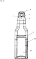
- the present invention relates to a fluid application device 90 as shown in FIG Fig. 6 and which is particularly suitable for use with pressure containers such as aerosol cans 30, or on fluid application devices which, using pumps, are suitable for conveying a disinfectant or care product in liquid, gel, emulsion or other form.
- the fluid application devices 90, 100 are all suitable for automatic fluid dispensing and have an application head 9 'on which a sensor 4 and a dispensing nozzle 5 for dispensing fluid are arranged.
- the nozzle 5 is fluidly connected to a reservoir 30.
- the application head 9 has on its upper side an integrated delivery arm, not shown separately, on which the nozzle, not shown in the figures, is arranged, pointing downward.
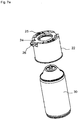
- the reservoir 30 is a pressurized aerosol can 30, as shown in Fig. 7a is shown, so that according to this realization of the fluid application device, means for conveying the fluid can be dispensed with.
- the cover 16 of the application head 9 ' can be pushed up by flanges on the cover 16 and on the head, which virtually form a rail guide. Pushing up can also be done automatically and hydraulically. In this case, a small motor is to be provided in the application head 9 'to carry out the displacement.
- a pressure vessel adapter piece which serves to hold the pressure vessel 30 in the application device, is arranged internally on the application head 9 ′.
- a pressure vessel adapter piece is in a simple form in 7a to 7d Shown: It is designed as a clamp holder, the clamp holder 24 having two wrap-around elements 25 'which are prestressed by means of a clamp spring 25 and which are arranged radially displaceably in the frame part 28 and thus clamp the head of the pressure cell 8'.
- the clamping springs 25 can in the attachment 22 according to 7b and c be supported.
- the actuating devices, here designed as set screws 26, for biasing and releasing the clamping springs 25 are also shown there. By turning the adjusting screw, the Diameter of the clamping device can be tapered or widened, depending on the size of the pressure cell to be held, which results in the adapter function.
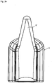
- Fig. 7e shows the clamping bracket 24 with the clamping springs 25 and the frame part 28 in an exploded view, for arrangement in the attachment 22, which is cylindrical and has a recess on its upper side with a support flange 22 'onto which the clamping bracket 24 can be placed.
- the in Fig. 7b shown clamp bracket but also directly into the adapter head 9 'of the fluid application device, as in Fig. 6 shown, used.
- the embodiment shown also shows a jacket piece 9, which virtually forms the "housing" of the application device. It is closed in the direction of the operating side and, however, has a cylindrical bulge, on the inside of which the pressure cell, which can be inserted from below, rests.
- a wall bracket 10 is provided on the rear side of the application device 90, here without electronic feedthroughs.
- the application device 90 as well as the application device 100, with the screw terminal 19, as attached to the wall bracket 10 and in Fig. 1d shown can be provided for attachment to a piece of furniture, such as a bed or table, so that advantageously a practitioner, the patient himself or the visitor can disinfect the hands at any time and thus prevent transmission of germs.
- FIG. 6 a collecting tray 11, which is cut directly to the jacket section and serves to collect excess fluid.
- it can be used ambulatory with an inserted absorbent, for example with pads, which absorb the excess fluid and which can be exchanged accordingly if the ambulatory collecting tray element 11 is designed for opening as suggested or at least allows the removal and replacement of pads.
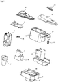
- FIG. 1a , b and c The fluid application devices shown, on the other hand, work with storage containers 30 ', from which the fluid can be seen by using a pump 1 Fig. 4 and Fig. 5h is promoted.
- this is a diaphragm pump 1, which is coupled to a one-way valve 6 and has an inlet which uses a piece of hose to see the fluid from the reservoir 30 ', see Fig. 1b , promotes.
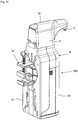
- the view in Fig. 4 shows an arrangement variant for the battery magazine 2 in a vertical orientation, not provided for the immediate arrangement under the cover 16 of the application head.
- the fluid connection to the nozzle 5 via the nozzle 5 ' is also off Fig. 2c and Fig. 2f evident.
- the application head 9 ′ has an application arm 15 designed as an extremity on the upper side, on the underside of which the nozzle 5 for dispensing the fluid is arranged.
- a sensor 4 can be provided on the vertical wall of the application head 9 ', but alternatively the sensor 4 could also be arranged directly behind the nozzle 5 or in front of the nozzle 5 when using a different design. It is also possible to use more than one sensor 4 if corresponding tasks other than triggering the pump with the sensor 4 are provided accordingly. Other tasks could include determining the body part size to be disinfected or supplied with fluid or its shape.
- the application head 9 ' has devices for body part detection almost directly through several optical sensors that allow reflection measurements.
- a jacket piece 9 extends downward from the application head 9 'via an adapter piece 8, which, preferably and in order to create a suitable look, at least partially surrounds the storage vessel and is advantageous, as in the embodiments of FIG Fig. 1a , b and c shown extends to the bottom of the reservoir 30 '.
- the embodiments shown allow the supply vessel 30 'to be inserted into the application device from the bottom front, so that the jacket piece 9 encompasses the supply vessel 30' in each case.
- the storage vessel 30 ' extends from below to an adapter piece 8 which is in Fig. 4 respectively Fig. 5j is clearly visible.
- This adapter piece 8 has a flange 8 'which is offset inwards from the edge and which is brought into engagement with an opening 18 of the storage vessel.
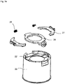
- the adapter piece 8 forms a bottom on which the pump 1, see Fig. 5h , and a battery magazine housing 17 ( Fig. 5i ) to accommodate a battery magazine 2, see Fig. 5f , can be held if it is not placed directly under the cover 16 ( Fig. 2e ).
- This floor has a passage opening 18 through which a delivery hose can be inserted.
- the battery magazine 2 can also be arranged at the top in the application head 9', the batteries being arranged lying down.
- This arrangement of the battery magazine 2 also shows Fig. 2d , which also the LEDs 21,21 'for displaying the Operational readiness of the device and also the actuating pushbuttons 31, 31 'for switching the device on and off, which are likewise operatively connected to the control and / or regulating circuit of the device, in a suitable manner via the circuit board 3.
- Fig. 2e shows an insight into the application head 9 'with the LEDs 21,21', the battery magazine 2 and the electronic connections of the batteries as well as the actuation buttons 31,31 '.
- the perspective side view of the head of the fluid application device 9 ' Fig. 2f represents the connection from the nozzle 5 via the connector 5 ′, which is connected to the hose 5 ′′, to the one-way valve 6 and the pump 1 and finally to the plug 7, which opens into the storage vessel, possibly via the adapter piece 8 as it complements in Fig. 2g is shown.
- the actuation push buttons 31, 31 'on the circuit board 3 and the LEDs 21, 21', which show whether the device is ready for operation or not, are also shown.
- Fig. 5f otherwise shows the sensor 4 provided with the reference symbol 4 as a separate element.
- the application head 9' can be provided with a cover 16. This can be attached in various ways, either by engagement by means of the flanges shown or also by a hinge element, or in another way and connected to the further housing of the application head 9 '. For example, by simply opening the application head 9 ', the battery magazine 2 can be replaced by removing it from the housing 17.
- Fig. 5b shows (see also Fig. 4 ) a circuit board 3, on which a control and regulation unit is arranged, which is in operative connection with the sensor 4.
- the sensor 4 can, not shown figuratively, be arranged on the underside of the circuit board 3.
- pump 1 begins via the operative connection by means of the control and regulation work and causes by opening the Valve 6 the conveying of fluid from the storage vessel 30 ′ and dispensing the fluid through the nozzle 5.
- the control device either allows pre-setting of fixed dispensing volumes, expressed in ml, to ensure that an actuator draws a sufficient amount of disinfectant or care fluid, or it can be a control device, which, depending on a hand size or a fluid quality, in Connection with the hand size or skin texture, which can be measured by the optoelectronic sensor, is regulated. It is therefore also possible to provide a plurality of sensors 4 in order to optically determine the outlines of a hand, for example in a simple manner. This advantageously ensures with the invention that a reliable dispensing of disinfectant is provided in relation to the necessary hand size-dependent care.
- the board 3 can with a cover 3 ', see Fig. 5a , are protected in the application head 9 '.
- Fig. 5b Shows in detail Fig. 5b the circuit board with the actuation buttons 31, 31 'and the LEDs 21, 21' which indicate the operating state.
- the circuit board cover 3 ' has corresponding receptacles and passages for these elements.
- Fig. 5c shows the viewing window 20 through which the LEDs 21, 21 'can be seen from the outside.
- the cover 16 of the application head 9 ' has a recess for the viewing window 20, see Fig. 5d .
- a counter can be provided in the application head 9 ′ or as a separate hand-held device in all embodiments of the application device 90, 100, for example with a fixed preset output quantity, which communicates with a signal transmitter in the application head.
- the counter counts the dispensed fluid cans and can thus follow the emptying of the storage vessel 30, 30 '.
- a receiving or reading device that displays the counted or the determined result or makes it readable, a person who is responsible for refilling the storage containers, for example, can determine how many cans or what quantity has been dispensed .
- Such counters can communicate via radio frequency.
- the device according to the invention can be programmed if a chip on the circuit board allows this, for example to set dispensing cans of fluid or to define a warning tone when emptied.
- Such programming can be carried out using a hand-held device that is also part of the counter device.
- the various application devices 90, 100 can be provided with corresponding codes, so that it is clearly clear to a person who is responsible for the refilling which of the application devices 90, 100 requires refilling.
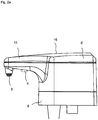
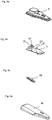
- Fig. 2a and 2 B the application head 9 '
- Fig. 2b shows a flange 8 'of the adapter piece 8 set back from the edge, which is arranged on the application head, for use in the opening of a storage vessel 30'.
- Fig. 2b a viewing window 20 present on the cover 16 of the application head 9 ', which makes it possible to take a look into the application head 9' and to determine whether the green LED 21 (see FIG.
- the LEDs 21, 21 can be connected to the control and regulating circuit. Of course, other colors can be selected for the LEDs 21, 21 ', or a blinking or other display mode can be set up.
- the counter If the counter outputs optically readable signals, it can be read out via the viewing window 20 by means of the corresponding reading device.
- FIG. 3a Also shown is an application device 100 according to the invention with the viewing window 20, in which the jacket piece 9 widens downward to accommodate large storage vessels, whereas the top view of such a device in FIG Fig. 3b shows an embodiment with a slightly narrower jacket element 9 from above.
- the other coat piece is also in Fig. 1c compared to Fig. 1b clarifies, in which the circumference of the casing element 9 and application head 9 'is approximately the same.
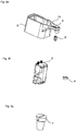
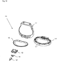
- FIG. 8a shows a collecting tray 11 which directly adjoins the lower edge of the jacket piece and which serves to absorb excess fluid that has been dispensed.
- the collecting tray 11 is designed as a double-bottomed element, on its upper side of the upper base 1 "it has through openings 11 'through which the fluid can flow downwards.
- absorbents such as pads, but also particulate material or absorbent fleece can be provided for absorbing the fluid on the lower floor, that is, between the two floors forming the double-bottomed element.
- FIG. 8a shows the side view of the Fig. 8a an electronic connector on the left edge, which has electronic connectors (e-contactor and connector 14, 14 ') at the connection of the collecting tray 11 to the casing element 9.
- a suction rotor 12 which can be started directly by appropriate electronic coupling of the drive to the sensor 4 when the sensor Trigger fluid output. As soon as the suction device is started, the excess fluid is safely absorbed by the collecting tray 11 and, with a corresponding design, is even drawn there to a collecting reservoir. This can be provided with the appropriate absorbent. While 8a and 8b show an approximately oval collecting tray 11 is a different design of the collecting tray 11 in Fig. 11 shown, a suction rotor 12 is also provided there. An upper floor 11 'of the catch tray 11, which is double-bottomed here, has the passage openings 11 ′′ at the edge in order to allow fluid to flow away; however, it can also be designed as a sieve or mesh component.
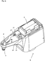
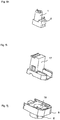
- Fig. 9a shows the transition of the drip tray 11 into the jacket element 9 'in an elegant curved embodiment, which is also in Fig. 9b can be seen from the side, the collecting tray 11 merges harmoniously directly into the jacket piece 9 '.
- a flattened design of the drip tray 11 is possible if a holding element holds a fluid absorption medium provided under the drip tray 11; in Fig. 9b however, a permeable top shelf 11 'is shown.
- the top bottoms of the drip tray 11 can be seen in the standing and lying position in the middle or on the right, while reference numeral 13 as a holding means for a pad shows a tray 13 'which can be clamped under the top tray 11'.
- Reference numeral 12 denotes the rotor and reference numerals 14, 14 'electronic connection elements or the contactor and the e-contact plug 14'.
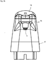
- Fig. 12 shows a view of such a collecting bowl equipped with suction rotor 12 from below.
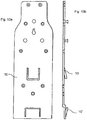
- FIG. 13a and 13b show two views of a suitable wall suspension element or a plate, which is particularly suitable for holding a fluid application device 90, 100 on a wall.
- the wall bracket 10 can, if necessary, have through openings for electronic lines.
- a clamp 10 ' is used to hold a drip tray 111, which is not attached to a jacket piece 9, under the application head 9' or the device with jacket piece 9.
- the wall bracket 10 can also be used to attach the fluid application device 90, 100 to a bed, table, shelf or the like and can thus be attached within a suitable range for an advised user.
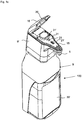
- Fig. 14 and Fig. 1d finally show that the jacket piece 9 can also be made such that the storage vessel 30 'can be covered.
- the jacket piece 9 has a front section 32 which can be hinged open.
- the joint here is a hinge which is attached to the lower edge of the jacket piece 9 and which allows the application device 100 to be opened for simple storage vessel exchange.
- the closed variant shows Fig. 1d
- Fig. 14 the opened variant shows.
- the front section of the jacket piece 9 can also be pushed or plugged on via a rail guide.
- the jacket piece 9 can also be designed such that it has a lift on its inside for flexible use of the device, which allows small storage vessels 30 'to be lifted up to the adapter 8.
- a one-piece wall bracket 10 with jacket piece 9 is shown in Fig. 16 shown:
- the lifting device comprises a contact surface 34 for the storage container 30 'and a rail element 34', so that the contact surface forms a vertically displaceable base on the casing piece 9. Small bottles can thus simply be placed on the contact surface 34 and moved to the adapter piece 8.
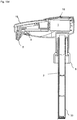
- FIG 15 b to d An embodiment of the fluid application device with an adapter piece 8 as a union nut is shown in FIG 15 b to d shown.
- the union nut is attached to a lower socket on the application head 9 'via a plug-on piece with a circumferential groove, and is thus connected to the latter.
- the conveying means there is a coaxial conveying tube 33, the inner tube of which forms the battery magazine 2, which is connected to the pump 1 and the sensor 4 for the energy supply.
- the pump 1 is arranged lying in the head 9 ', which has a shapely, narrow application arm 15.
- a storage bottle with disinfectant or another fluid that is equipped with this application device can be inserted into a holder to improve the stability.
Landscapes
- Health & Medical Sciences (AREA)
- Public Health (AREA)
- Engineering & Computer Science (AREA)
- Surgery (AREA)
- Chemical & Material Sciences (AREA)
- Dispersion Chemistry (AREA)
- Mechanical Engineering (AREA)
- Life Sciences & Earth Sciences (AREA)
- Biomedical Technology (AREA)
- Pathology (AREA)
- Oral & Maxillofacial Surgery (AREA)
- Heart & Thoracic Surgery (AREA)
- Medical Informatics (AREA)
- Molecular Biology (AREA)
- Animal Behavior & Ethology (AREA)
- General Health & Medical Sciences (AREA)
- Nuclear Medicine, Radiotherapy & Molecular Imaging (AREA)
- Veterinary Medicine (AREA)
- Containers And Packaging Bodies Having A Special Means To Remove Contents (AREA)
Claims (17)
- Dispositif d'application de fluide (90) avec une distribution de fluide, qui comprend un réservoir de stockage (30), un boîtier (9), une pièce d'adaptation pour maintenir le réservoir de stockage (30) et une tête d'application (9') qui est disposée au-dessus du réservoir de stockage (30') et qui présente une buse (5) pour la distribution de fluide, dans lequel- la buse est en liaison fluidique avec un réservoir de stockage (30),- le réservoir de stockage (30) est un récipient sous surpression (8') qui présente une sortie qui peut être ouverte et fermée par une vanne, et- le boîtier (9) et la tête d'application (9') sont des composants séparés, caractérisé en ce que la tête d'application (9') présente sur son côté supérieur un bras d'application (15) sur lequel la buse (5) est disposée en étant dirigée vers le bas, la pièce d'adaptation destinée à maintenir le réservoir de stockage (30) étant disposée sur la tête d'application (9') et présentant un support de serrage qui comprend deux éléments de serrage (27) précontraints chacun au moyen d'un ressort de serrage (25), une partie cadre (28) et un dispositif d'actionnement pour précontraindre et libérer les ressorts de serrage (25), et le dispositif d'application de fluide présente une distribution automatique de fluide, la tête d'application (9') comportant au moins un capteur (4) et une unité de commande pour l'ouverture et la fermeture commandées par capteur de la vanne qui est reliée par une pièce de liaison à la buse (5) pour la distribution du fluide.
- Dispositif d'application de fluide (100) selon la revendication 1,
caractérisé en ce que
les deux éléments de serrage (27) précontraints chacun au moyen d'un ressort de serrage (25) sont disposés de manière à pouvoir coulisser radialement dans une partie cadre (28), les ressorts de serrage (25) étant disposés en prenant appui extérieurement contre- un élément rapporté (22) qui peut être disposé sur la tête d'application (9') ou- contre une paroi intérieure de la tête d'application (9'). - Dispositif d'application de fluide (100) selon la revendication 1 ou 2 caractérisé en ce que le dispositif d'actionnement est une vis de réglage (26).
- Dispositif d'application de fluide (100) avec distribution automatique de fluide, qui comprend un réservoir de stockage (30') et une tête d'application (9') qui est disposée au-dessus du réservoir de stockage (30') et qui présente au moins un capteur (4) et une buse (5) pour la distribution de fluide, le capteur (4) étant relié fonctionnellement à une pompe (1) reliée à la buse (5) et raccordée au réservoir de stockage (30'), la tête d'application (9') présentant un bras d'application (15) sur lequel la buse (5) est disposée en étant dirigée vers le bas, et la pompe (1), qui peut être commandée par le capteur (4) et entraînée par moteur, étant disposée dans la tête d'application (9') avec une entrée et une sortie et reliée du côté de la sortie par une vanne (6), au moyen d'un raccord de tuyau ou de tube (5"), à une tubulure de liaison (5') de la buse (5) pour la distribution du fluide,
caractérisé en ce qu'un boîtier (9) et une pièce d'adaptation (8) sont prévus pour maintenir le réservoir de stockage, le boîtier (9) et la tête d'application (9') étant des composants séparés, la pièce d'adaptation (8) étant disposée sur la tête d'application (9') et un bord extérieur de la pièce d'adaptation (8') étant relié au boîtier (9) qui entoure au moins une partie d'un côté arrière du réservoir de stockage (30, 30'), le bras d'application (15) étant disposé sur le côté supérieur de la tête d'application (9'), et la pompe (1) étant disposée au-dessus de la pièce d'adaptation (8) au moyen de laquelle la tête d'application (9') peut être reliée de manière étanche aux fluides au réservoir de stockage (30'). - Dispositif d'application de fluide (100) selon la revendication 4,
caractérisé en ce que la pièce d'adaptation (8) est disposée de manière permanente ou amovible sur la tête d'application (9'), une face inférieure de la pièce d'adaptation (8) pouvant être mise en prise avec une ouverture du réservoir de stockage (30'), et un dispositif de transport, en particulier un tuyau ou un tube (33), s'étendant du côté d'entrée de la pompe (1) dans le réservoir de stockage (30'). - Dispositif d'application de fluide (100) selon la revendication 4 ou 5,
caractérisé en ce que la pièce d'adaptation (8) présente une face supérieure qui peut être reliée par complémentarité de forme à la tête d'application (9') et dont la face inférieure présente une bride, en particulier une bride (8') qui est décalée vers l'intérieur à partir d'un bord de la pièce d'adaptation et qui peut être mise en prise avec l'ouverture du réservoir de stockage (30'), et le dispositif de transport étant un tuyau de transport qui s'étend du côté d'entrée de la pompe (1) dans le réservoir de stockage (30') à travers une ouverture (18) prévue dans la pièce d'adaptation (8). - Dispositif d'application de fluide (90, 100) selon l'une des revendications précédentes,
caractérisé en ce que le capteur (4) ou les capteurs (4) est/sont en particulier un ou des capteur(s) optique(s) ou optoélectronique(s) (4), au moins un capteur (4) étant disposé sur le bras d'application (15) en étant dirigé vers le bas ou sur la tête d'application (9') en étant dirigé vers la buse (5). - Dispositif d'application de fluide (100) selon au moins l'une des revendications 4 à 7,
caractérisé en ce que la pompe pouvant être commandée par le ou les capteurs est une pompe à membrane qui est couplée fonctionnellement côté sortie à une vanne unidirectionnelle (6), la pompe à membrane étant couplée à une alimentation en énergie, en particulier à un magasin à piles (2) qui peut être remplacé dans son ensemble. - Dispositif d'application de fluide (90, 100) selon au moins l'une des revendications 1 à 8,
caractérisé en ce que l'unité de commande pour commander la vanne est également conçue comme une unité de régulation et est disposée en particulier sur une carte de circuit imprimé (3), un volume de distribution du fluide pouvant en particulier être prédéterminé. - Dispositif d'application de fluide (90, 100) selon l'une des revendications précédentes,
caractérisé en ce que dans la tête d'application (9') sont en outre disposés- un dispositif pour mesurer la densité du fluide et/ou- un dispositif pour détecter la nature de la main et/ou de la peau et/ou- un dispositif pour déterminer la taille de la main, le dispositif pour déterminer la taille de la main étant couplé fonctionnellement au dispositif de commande et/ou de régulation. - Dispositif d'application de fluide (100) selon au moins l'une des revendications 1 à 3, ou 5 à 10, si dépendant de 1 à 3,
caractérisé en ce qu'un bord extérieur de la pièce d'adaptation (8') est relié à une pièce d'enveloppe (9) qui s'étend vers le bas à partir de la pièce d'adaptation (8) et qui entoure au moins une partie d'un côté arrière du réservoir de stockage (30, 30'). - Dispositif d'application de fluide (90, 100) selon l'une des revendications précédentes,
caractérisé en ce que le boîtier (9) s'étend au moins jusqu'en dessous du réservoir de stockage (30, 30') et, en particulier au bord inférieur du boîtier (9), est disposé un bac collecteur (11) qui s'étend en dessous du bras d'application (15) selon une extension de ce dernier,
et/ou dans lequel le bac collecteur (11) présente un double fond, dont le fond supérieur (11') présente une pluralité d'ouvertures de passage (11") pour le fluide,
et dans lequel, de préférence, un dispositif d'aspiration, en particulier un rotor d'aspiration (12), est disposé dans le bac collecteur, en particulier sous le fond supérieur (11'), et en contact fluidique avec les ouvertures de passage (11") pour le fluide pour l'aspiration de fluide. - Dispositif d'application de fluide (90, 100) selon la revendication 12,
caractérisé en ce qu'au moins un moyen d'absorption de fluide est disposé dans le bac collecteur (11), en particulier sous le fond supérieur (11') qui présente la pluralité d'ouvertures de passage (11") pour le fluide, le moyen d'absorption étant en particulier un non-tissé absorbant ou un coussinet absorbant,
et/ou que le bac collecteur (11) est disposé de manière amovible sur le boîtier (9), et/ou qu'une traversée pour une ligne d'alimentation en énergie est prévue à un point de raccordement du bac collecteur (11) au boîtier (9). - Dispositif d'application de fluide (100) selon au moins l'une des revendications 4 à 13,
caractérisé en ce que la pièce d'adaptation (8) est conçue comme un écrou-raccord, est reliée à la tête d'application (9') et présente un filetage qui peut être vissé avec un filetage extérieur de col présent sur le réservoir de stockage (30'), et dans lequel le dispositif de transport est un tube de transport à double paroi (33), en particulier un tube de transport coaxial (33), dont le tube intérieur forme un magasin à piles (2) qui est relié électriquement au moins à la pompe (1), en particulier à la pompe et à un ou plusieurs consommateurs d'énergie présents dans la tête d'application (9') pour leur alimentation en énergie. - Dispositif d'application de fluide (90, 100) selon au moins l'une des revendications précédentes,
caractérisé en ce que le dispositif d'application de fluide (90, 100) est conçu- pour une disposition sur pied ou- pour une suspension murale, en particulier pour une suspension murale au moyen d'un support mural (10) disposé sur le boîtier (9) ou formé d'une seule pièce avec celui-ci, avec ou sans traversées électroniques, ou pour être disposé sur un meuble ou un autre bras de support vertical au moyen d'une pièce de serrage à vis (19) fixée au support mural (10). - Dispositif d'application de fluide (90, 100) selon au moins l'une des revendications précédentes,
caractérisé en ce que le boîtier (9) ou un support mural (10) formé d'une seule pièce avec celui-ci présente intérieurement un dispositif de levage (34) constitué d'une surface d'appui (34) qui est disposée de manière à pouvoir coulisser verticalement dans un élément de rail (34'). - Dispositif d'application de fluide (90, 100) selon l'une des revendications précédentes,
caractérisé en ce que le boîtier (9) présente une partie avant (32) qui- peut être relevée de manière articulée et à laquelle il est relié par une charnière reliée à son bord inférieur, ou qui- peut être enfilée par le bas au moyen d'un rail.
Priority Applications (2)
| Application Number | Priority Date | Filing Date | Title |
|---|---|---|---|
| EP11006973.9A EP2561820B1 (fr) | 2011-08-26 | 2011-08-26 | Dispositif d'application de fluide sans contact |
| PCT/EP2012/003597 WO2013029770A1 (fr) | 2011-08-26 | 2012-08-27 | Dispositif applicateur de fluide sans contact |
Applications Claiming Priority (1)
| Application Number | Priority Date | Filing Date | Title |
|---|---|---|---|
| EP11006973.9A EP2561820B1 (fr) | 2011-08-26 | 2011-08-26 | Dispositif d'application de fluide sans contact |
Publications (2)
| Publication Number | Publication Date |
|---|---|
| EP2561820A1 EP2561820A1 (fr) | 2013-02-27 |
| EP2561820B1 true EP2561820B1 (fr) | 2020-07-22 |
Family
ID=46968119
Family Applications (1)
| Application Number | Title | Priority Date | Filing Date |
|---|---|---|---|
| EP11006973.9A Active EP2561820B1 (fr) | 2011-08-26 | 2011-08-26 | Dispositif d'application de fluide sans contact |
Country Status (2)
| Country | Link |
|---|---|
| EP (1) | EP2561820B1 (fr) |
| WO (1) | WO2013029770A1 (fr) |
Families Citing this family (8)
| Publication number | Priority date | Publication date | Assignee | Title |
|---|---|---|---|---|
| CA2817604A1 (fr) | 2013-02-13 | 2014-08-13 | Earl Roy Finch | Appareil et methode d'humidification de produits sanitaires en papier |
| DE102014010926A1 (de) | 2014-07-28 | 2016-01-28 | Hartmut J. Schneider | Berührungsloser Spender zur Ausgabe von flüssigen Medien |
| NL2014661B1 (nl) * | 2015-04-17 | 2016-12-30 | Nosoapcompany B V | Opvanginrichting en desinfectie-inrichting met opvanginrichting. |
| USD806556S1 (en) | 2015-07-16 | 2018-01-02 | Clean Ends Inc. | Handheld liquid dispenser |
| WO2018038686A1 (fr) * | 2016-08-23 | 2018-03-01 | Karaman Nurettin | Distributeur de mousse |
| CN111184941A (zh) * | 2020-02-26 | 2020-05-22 | 上海与非日用品有限公司 | 一种免接触式消毒液喷射器 |
| CN111938480B (zh) * | 2020-08-27 | 2025-03-18 | 浙江英特汉莎智能科技有限公司 | 一种感应式皂液器 |
| CN112722522B (zh) * | 2020-12-31 | 2022-10-14 | 宁波厨聚厨房科技有限公司 | 一种用于皂液瓶的送料机构 |
Citations (3)
| Publication number | Priority date | Publication date | Assignee | Title |
|---|---|---|---|---|
| US20020074349A1 (en) * | 2000-11-27 | 2002-06-20 | Michaels Kenneth W. | Post-foaming gel, container therefor and apparatus and method for heating and dispensing |
| US20040217137A1 (en) * | 2002-04-26 | 2004-11-04 | Heiner Ophardt | Manual or pump assist fluid dispenser |
| DE202007012093U1 (de) * | 2007-08-29 | 2007-10-25 | Weinmann Gmbh | Dosierpumpe und Hygienespender |
Family Cites Families (16)
| Publication number | Priority date | Publication date | Assignee | Title |
|---|---|---|---|---|
| US3419188A (en) * | 1967-02-13 | 1968-12-31 | Beverly R L Matchett | Dispenser |
| DE3505893A1 (de) | 1985-02-20 | 1986-08-21 | GVB SANIMED Hygiene- und Medizintechnik GmbH, 3070 Nienburg | Spender |
| DE3531385A1 (de) | 1985-09-03 | 1987-03-05 | Klaus Weber | Dosiervorrichtung zum absatzweisen abgeben eines fluessigen stoffes |
| CA2024788A1 (fr) * | 1989-09-18 | 1991-03-19 | Zoltan Cseri | Doseur de savon, a commande pneumatique |
| US6276565B1 (en) * | 1999-05-11 | 2001-08-21 | Arichell Technologies, Inc. | Gas-driven liquid dispenser employing separate pressurized-gas source |
| US6551739B1 (en) * | 2000-06-23 | 2003-04-22 | Yi-Chen Chen | DC supplying arrangement for soap feeding device |
| DE20122888U1 (de) | 2001-01-30 | 2009-03-26 | Schneider, Hartmut J. | Spender für Reinigungsmittel |
| EP1406530A1 (fr) * | 2001-07-13 | 2004-04-14 | Scheepers, Roger Basil Lawson | Distributeur d'un produit fluide |
| DE10258272A1 (de) | 2002-12-13 | 2004-07-08 | Schneider, Hartmut J. | Vorrichtung zum Ausbringen von Desinfektions- und Reinigungsmitteln insbesondere für Hände |
| US20040226962A1 (en) * | 2003-05-15 | 2004-11-18 | Richard Mazursky | Automatic liquid dispenser |
| DE102004063782B4 (de) * | 2004-12-30 | 2007-08-16 | Ophardt Product Kg | Vorrichtung zum Ein- und Ausschalten berührungslos bedienbarer Handreinigungs- und Desinfektionsmittelspender |
| GB0512258D0 (en) * | 2005-06-16 | 2005-07-27 | Mindinsync Ltd | Dispensing apparatus |
| US20070000941A1 (en) * | 2005-07-01 | 2007-01-04 | Hadden David M | Motion-activated soap dispenser |
| US8096445B2 (en) * | 2007-02-01 | 2012-01-17 | Simplehuman, Llc | Electric soap dispenser |
| DE102009008022B4 (de) | 2009-02-05 | 2017-02-09 | Hartmut J. Schneider | Dosiervorrichtung für ein Hygienefluid |
| US8245879B2 (en) * | 2009-03-13 | 2012-08-21 | Gojo Industries, Inc. | Touch-free biometric-enabled dispenser |
-
2011
- 2011-08-26 EP EP11006973.9A patent/EP2561820B1/fr active Active
-
2012
- 2012-08-27 WO PCT/EP2012/003597 patent/WO2013029770A1/fr not_active Ceased
Patent Citations (3)
| Publication number | Priority date | Publication date | Assignee | Title |
|---|---|---|---|---|
| US20020074349A1 (en) * | 2000-11-27 | 2002-06-20 | Michaels Kenneth W. | Post-foaming gel, container therefor and apparatus and method for heating and dispensing |
| US20040217137A1 (en) * | 2002-04-26 | 2004-11-04 | Heiner Ophardt | Manual or pump assist fluid dispenser |
| DE202007012093U1 (de) * | 2007-08-29 | 2007-10-25 | Weinmann Gmbh | Dosierpumpe und Hygienespender |
Also Published As
| Publication number | Publication date |
|---|---|
| WO2013029770A1 (fr) | 2013-03-07 |
| EP2561820A1 (fr) | 2013-02-27 |
Similar Documents
| Publication | Publication Date | Title |
|---|---|---|
| EP2561820B1 (fr) | Dispositif d'application de fluide sans contact | |
| DE102009049261B4 (de) | Wanddosierspender | |
| EP2695548B1 (fr) | Distributeur pour le dosage de fluides pouvant s'écouler | |
| DE10026118C2 (de) | Vorrichtung zum Befeuchten von flüssigkeitsaufnehmenden Mitteln, wie Toilettenpapier | |
| EP1688081B1 (fr) | Utensile de nettoyage | |
| DE202020002169U1 (de) | Spender für fluides Fördergut, insbesondere Handdesinfektionsmittel | |
| EP3461382B1 (fr) | Réservoir de stockage à pompe manuelle pourvu de tuyau d'évacuation allongé et distributeur de dosage pourvu de réservoir de stockage et adaptateur de montage du réservoir de stockage dans le réservoir | |
| EP0362835A1 (fr) | Conteneur et conteneur pour produits désinfectants, crème savon, crème de main, produits pour soigner la peau, ou similaires | |
| EP3148395A1 (fr) | Dispositif de nettoyage et/ou de désinfection du rebord d'un article de vaisselle | |
| US6964536B1 (en) | Lotion applicator | |
| DE102009008022B4 (de) | Dosiervorrichtung für ein Hygienefluid | |
| DE102014107679B4 (de) | Reinigungs- und/oder Desinfektionsvorrichtung für den Mundrand eines Gedeckartikels | |
| AT511813B1 (de) | Wärmevorrichtung für flaschen- oder tubenartige Behälter | |
| DE3036523C2 (de) | Ausgabevorrichtung für flüssige oder pastöse Güter | |
| EP3174560B1 (fr) | Dispositif pour chauffer ou stériliser un article de puériculture | |
| AT403568B (de) | Befestigung eines ausgabekopfes an einer eine desinfektionsflüssigkeit enthaltenden flasche und zwischenstück für eine solche befestigung | |
| DE19737749C1 (de) | Flüssigkeitsspender, insbesondere Flüssigmedikamentenspender, für die tropfenweise dosierbare Abgabe einer Flüssigkeit, insbesondere eines Flüssigmedikaments | |
| DE202019106936U1 (de) | Behälter für einen Spender | |
| DE202006007035U1 (de) | Spender für flüssige und/oder pasteuse Medien, insbesondere Seifen- und Desinfektionsmittelspender | |
| EP2322066B1 (fr) | Procédé et distributeur destinés à distribuer des portions d'un fluide | |
| CH698160B1 (de) | Einrichtung zur Erzeugung eines Flüssigkeitsstrahles zum Reinigen bzw. Dekontaminieren von Wunden oder infizierten Körperstellen. | |
| DE102014007518B4 (de) | Spendereinrichtung mit Flaschenbetätigung | |
| DE20014126U1 (de) | Reinigungsgerät | |
| DE3619192A1 (de) | Fluessigkeitsspender mit halterung | |
| DE10231756A1 (de) | Hygiene gerechter Reinigungsautomat für WC-Sitz |
Legal Events
| Date | Code | Title | Description |
|---|---|---|---|
| PUAI | Public reference made under article 153(3) epc to a published international application that has entered the european phase |
Free format text: ORIGINAL CODE: 0009012 |
|
| AK | Designated contracting states |
Kind code of ref document: A1 Designated state(s): AL AT BE BG CH CY CZ DE DK EE ES FI FR GB GR HR HU IE IS IT LI LT LU LV MC MK MT NL NO PL PT RO RS SE SI SK SM TR |
|
| AX | Request for extension of the european patent |
Extension state: BA ME |
|
| 17P | Request for examination filed |
Effective date: 20130826 |
|
| RBV | Designated contracting states (corrected) |
Designated state(s): AL AT BE BG CH CY CZ DE DK EE ES FI FR GB GR HR HU IE IS IT LI LT LU LV MC MK MT NL NO PL PT RO RS SE SI SK SM TR |
|
| RAP1 | Party data changed (applicant data changed or rights of an application transferred) |
Owner name: PRISMAN PHARMA INTERNATIONAL AG Owner name: SCHNEIDER, HARTMUT J. |
|
| RIN1 | Information on inventor provided before grant (corrected) |
Inventor name: SCHNEIDER, HARTMUT J. Inventor name: METZGER, STEPHAN |
|
| 17Q | First examination report despatched |
Effective date: 20160216 |
|
| RAP1 | Party data changed (applicant data changed or rights of an application transferred) |
Owner name: PRISMAN PHARMA INTERNATIONAL AG Owner name: SCHNEIDER, HARTMUT J. |
|
| RIN1 | Information on inventor provided before grant (corrected) |
Inventor name: SCHNEIDER, HARTMUT J. Inventor name: METZGER, STEPHAN |
|
| REG | Reference to a national code |
Ref country code: DE Ref legal event code: R079 Ref document number: 502011016809 Country of ref document: DE Free format text: PREVIOUS MAIN CLASS: A61B0019000000 Ipc: B65D0083260000 |
|
| GRAP | Despatch of communication of intention to grant a patent |
Free format text: ORIGINAL CODE: EPIDOSNIGR1 |
|
| STAA | Information on the status of an ep patent application or granted ep patent |
Free format text: STATUS: GRANT OF PATENT IS INTENDED |
|
| RIC1 | Information provided on ipc code assigned before grant |
Ipc: A61B 90/80 20160101ALI20200113BHEP Ipc: B05B 9/04 20060101ALI20200113BHEP Ipc: B05B 9/043 20060101ALI20200113BHEP Ipc: B65D 83/26 20060101AFI20200113BHEP Ipc: B05B 12/12 20060101ALI20200113BHEP Ipc: B65D 83/38 20060101ALI20200113BHEP Ipc: A47K 5/12 20060101ALI20200113BHEP |
|
| INTG | Intention to grant announced |
Effective date: 20200207 |
|
| RAP1 | Party data changed (applicant data changed or rights of an application transferred) |
Owner name: SCHNEIDER, HARTMUT J. Owner name: PRISMAN GMBH |
|
| GRAS | Grant fee paid |
Free format text: ORIGINAL CODE: EPIDOSNIGR3 |
|
| GRAA | (expected) grant |
Free format text: ORIGINAL CODE: 0009210 |
|
| STAA | Information on the status of an ep patent application or granted ep patent |
Free format text: STATUS: THE PATENT HAS BEEN GRANTED |
|
| AK | Designated contracting states |
Kind code of ref document: B1 Designated state(s): AL AT BE BG CH CY CZ DE DK EE ES FI FR GB GR HR HU IE IS IT LI LT LU LV MC MK MT NL NO PL PT RO RS SE SI SK SM TR |
|
| REG | Reference to a national code |
Ref country code: GB Ref legal event code: FG4D Free format text: NOT ENGLISH |
|
| REG | Reference to a national code |
Ref country code: CH Ref legal event code: EP |
|
| REG | Reference to a national code |
Ref country code: DE Ref legal event code: R096 Ref document number: 502011016809 Country of ref document: DE |
|
| REG | Reference to a national code |
Ref country code: AT Ref legal event code: REF Ref document number: 1293178 Country of ref document: AT Kind code of ref document: T Effective date: 20200815 |
|
| REG | Reference to a national code |
Ref country code: IE Ref legal event code: FG4D Free format text: LANGUAGE OF EP DOCUMENT: GERMAN |
|
| REG | Reference to a national code |
Ref country code: LT Ref legal event code: MG4D |
|
| PG25 | Lapsed in a contracting state [announced via postgrant information from national office to epo] |
Ref country code: FI Free format text: LAPSE BECAUSE OF FAILURE TO SUBMIT A TRANSLATION OF THE DESCRIPTION OR TO PAY THE FEE WITHIN THE PRESCRIBED TIME-LIMIT Effective date: 20200722 Ref country code: GR Free format text: LAPSE BECAUSE OF FAILURE TO SUBMIT A TRANSLATION OF THE DESCRIPTION OR TO PAY THE FEE WITHIN THE PRESCRIBED TIME-LIMIT Effective date: 20201023 Ref country code: NO Free format text: LAPSE BECAUSE OF FAILURE TO SUBMIT A TRANSLATION OF THE DESCRIPTION OR TO PAY THE FEE WITHIN THE PRESCRIBED TIME-LIMIT Effective date: 20201022 Ref country code: SE Free format text: LAPSE BECAUSE OF FAILURE TO SUBMIT A TRANSLATION OF THE DESCRIPTION OR TO PAY THE FEE WITHIN THE PRESCRIBED TIME-LIMIT Effective date: 20200722 Ref country code: LT Free format text: LAPSE BECAUSE OF FAILURE TO SUBMIT A TRANSLATION OF THE DESCRIPTION OR TO PAY THE FEE WITHIN THE PRESCRIBED TIME-LIMIT Effective date: 20200722 Ref country code: PT Free format text: LAPSE BECAUSE OF FAILURE TO SUBMIT A TRANSLATION OF THE DESCRIPTION OR TO PAY THE FEE WITHIN THE PRESCRIBED TIME-LIMIT Effective date: 20201123 Ref country code: ES Free format text: LAPSE BECAUSE OF FAILURE TO SUBMIT A TRANSLATION OF THE DESCRIPTION OR TO PAY THE FEE WITHIN THE PRESCRIBED TIME-LIMIT Effective date: 20200722 Ref country code: BG Free format text: LAPSE BECAUSE OF FAILURE TO SUBMIT A TRANSLATION OF THE DESCRIPTION OR TO PAY THE FEE WITHIN THE PRESCRIBED TIME-LIMIT Effective date: 20201022 Ref country code: HR Free format text: LAPSE BECAUSE OF FAILURE TO SUBMIT A TRANSLATION OF THE DESCRIPTION OR TO PAY THE FEE WITHIN THE PRESCRIBED TIME-LIMIT Effective date: 20200722 |
|
| PG25 | Lapsed in a contracting state [announced via postgrant information from national office to epo] |
Ref country code: IS Free format text: LAPSE BECAUSE OF FAILURE TO SUBMIT A TRANSLATION OF THE DESCRIPTION OR TO PAY THE FEE WITHIN THE PRESCRIBED TIME-LIMIT Effective date: 20201122 Ref country code: LV Free format text: LAPSE BECAUSE OF FAILURE TO SUBMIT A TRANSLATION OF THE DESCRIPTION OR TO PAY THE FEE WITHIN THE PRESCRIBED TIME-LIMIT Effective date: 20200722 Ref country code: RS Free format text: LAPSE BECAUSE OF FAILURE TO SUBMIT A TRANSLATION OF THE DESCRIPTION OR TO PAY THE FEE WITHIN THE PRESCRIBED TIME-LIMIT Effective date: 20200722 Ref country code: PL Free format text: LAPSE BECAUSE OF FAILURE TO SUBMIT A TRANSLATION OF THE DESCRIPTION OR TO PAY THE FEE WITHIN THE PRESCRIBED TIME-LIMIT Effective date: 20200722 |
|
| PG25 | Lapsed in a contracting state [announced via postgrant information from national office to epo] |
Ref country code: NL Free format text: LAPSE BECAUSE OF FAILURE TO SUBMIT A TRANSLATION OF THE DESCRIPTION OR TO PAY THE FEE WITHIN THE PRESCRIBED TIME-LIMIT Effective date: 20200722 |
|
| REG | Reference to a national code |
Ref country code: CH Ref legal event code: PL |
|
| REG | Reference to a national code |
Ref country code: DE Ref legal event code: R097 Ref document number: 502011016809 Country of ref document: DE |
|
| PG25 | Lapsed in a contracting state [announced via postgrant information from national office to epo] |
Ref country code: RO Free format text: LAPSE BECAUSE OF FAILURE TO SUBMIT A TRANSLATION OF THE DESCRIPTION OR TO PAY THE FEE WITHIN THE PRESCRIBED TIME-LIMIT Effective date: 20200722 Ref country code: SM Free format text: LAPSE BECAUSE OF FAILURE TO SUBMIT A TRANSLATION OF THE DESCRIPTION OR TO PAY THE FEE WITHIN THE PRESCRIBED TIME-LIMIT Effective date: 20200722 Ref country code: MC Free format text: LAPSE BECAUSE OF FAILURE TO SUBMIT A TRANSLATION OF THE DESCRIPTION OR TO PAY THE FEE WITHIN THE PRESCRIBED TIME-LIMIT Effective date: 20200722 Ref country code: LU Free format text: LAPSE BECAUSE OF NON-PAYMENT OF DUE FEES Effective date: 20200826 Ref country code: LI Free format text: LAPSE BECAUSE OF NON-PAYMENT OF DUE FEES Effective date: 20200831 Ref country code: IT Free format text: LAPSE BECAUSE OF FAILURE TO SUBMIT A TRANSLATION OF THE DESCRIPTION OR TO PAY THE FEE WITHIN THE PRESCRIBED TIME-LIMIT Effective date: 20200722 Ref country code: CH Free format text: LAPSE BECAUSE OF NON-PAYMENT OF DUE FEES Effective date: 20200831 Ref country code: CZ Free format text: LAPSE BECAUSE OF FAILURE TO SUBMIT A TRANSLATION OF THE DESCRIPTION OR TO PAY THE FEE WITHIN THE PRESCRIBED TIME-LIMIT Effective date: 20200722 Ref country code: DK Free format text: LAPSE BECAUSE OF FAILURE TO SUBMIT A TRANSLATION OF THE DESCRIPTION OR TO PAY THE FEE WITHIN THE PRESCRIBED TIME-LIMIT Effective date: 20200722 Ref country code: EE Free format text: LAPSE BECAUSE OF FAILURE TO SUBMIT A TRANSLATION OF THE DESCRIPTION OR TO PAY THE FEE WITHIN THE PRESCRIBED TIME-LIMIT Effective date: 20200722 |
|
| REG | Reference to a national code |
Ref country code: BE Ref legal event code: MM Effective date: 20200831 |
|
| PLBE | No opposition filed within time limit |
Free format text: ORIGINAL CODE: 0009261 |
|
| STAA | Information on the status of an ep patent application or granted ep patent |
Free format text: STATUS: NO OPPOSITION FILED WITHIN TIME LIMIT |
|
| PG25 | Lapsed in a contracting state [announced via postgrant information from national office to epo] |
Ref country code: AL Free format text: LAPSE BECAUSE OF FAILURE TO SUBMIT A TRANSLATION OF THE DESCRIPTION OR TO PAY THE FEE WITHIN THE PRESCRIBED TIME-LIMIT Effective date: 20200722 |
|
| GBPC | Gb: european patent ceased through non-payment of renewal fee |
Effective date: 20201022 |
|
| 26N | No opposition filed |
Effective date: 20210423 |
|
| PG25 | Lapsed in a contracting state [announced via postgrant information from national office to epo] |
Ref country code: SK Free format text: LAPSE BECAUSE OF FAILURE TO SUBMIT A TRANSLATION OF THE DESCRIPTION OR TO PAY THE FEE WITHIN THE PRESCRIBED TIME-LIMIT Effective date: 20200722 |
|
| PG25 | Lapsed in a contracting state [announced via postgrant information from national office to epo] |
Ref country code: FR Free format text: LAPSE BECAUSE OF NON-PAYMENT OF DUE FEES Effective date: 20200922 |
|
| PG25 | Lapsed in a contracting state [announced via postgrant information from national office to epo] |
Ref country code: BE Free format text: LAPSE BECAUSE OF NON-PAYMENT OF DUE FEES Effective date: 20200831 Ref country code: SI Free format text: LAPSE BECAUSE OF FAILURE TO SUBMIT A TRANSLATION OF THE DESCRIPTION OR TO PAY THE FEE WITHIN THE PRESCRIBED TIME-LIMIT Effective date: 20200722 Ref country code: GB Free format text: LAPSE BECAUSE OF NON-PAYMENT OF DUE FEES Effective date: 20201022 Ref country code: IE Free format text: LAPSE BECAUSE OF NON-PAYMENT OF DUE FEES Effective date: 20200826 |
|
| REG | Reference to a national code |
Ref country code: NL Ref legal event code: MP Effective date: 20200722 |
|
| REG | Reference to a national code |
Ref country code: AT Ref legal event code: MM01 Ref document number: 1293178 Country of ref document: AT Kind code of ref document: T Effective date: 20200826 |
|
| PG25 | Lapsed in a contracting state [announced via postgrant information from national office to epo] |
Ref country code: AT Free format text: LAPSE BECAUSE OF NON-PAYMENT OF DUE FEES Effective date: 20200826 |
|
| PGFP | Annual fee paid to national office [announced via postgrant information from national office to epo] |
Ref country code: DE Payment date: 20211027 Year of fee payment: 11 |
|
| PG25 | Lapsed in a contracting state [announced via postgrant information from national office to epo] |
Ref country code: TR Free format text: LAPSE BECAUSE OF FAILURE TO SUBMIT A TRANSLATION OF THE DESCRIPTION OR TO PAY THE FEE WITHIN THE PRESCRIBED TIME-LIMIT Effective date: 20200722 Ref country code: MT Free format text: LAPSE BECAUSE OF FAILURE TO SUBMIT A TRANSLATION OF THE DESCRIPTION OR TO PAY THE FEE WITHIN THE PRESCRIBED TIME-LIMIT Effective date: 20200722 Ref country code: CY Free format text: LAPSE BECAUSE OF FAILURE TO SUBMIT A TRANSLATION OF THE DESCRIPTION OR TO PAY THE FEE WITHIN THE PRESCRIBED TIME-LIMIT Effective date: 20200722 |
|
| PG25 | Lapsed in a contracting state [announced via postgrant information from national office to epo] |
Ref country code: MK Free format text: LAPSE BECAUSE OF FAILURE TO SUBMIT A TRANSLATION OF THE DESCRIPTION OR TO PAY THE FEE WITHIN THE PRESCRIBED TIME-LIMIT Effective date: 20200722 |
|
| REG | Reference to a national code |
Ref country code: DE Ref legal event code: R119 Ref document number: 502011016809 Country of ref document: DE |
|
| PG25 | Lapsed in a contracting state [announced via postgrant information from national office to epo] |
Ref country code: DE Free format text: LAPSE BECAUSE OF NON-PAYMENT OF DUE FEES Effective date: 20230301 |