EP2561919A1 - Système de traitement des gaz d'échappement muni d'un équipement d'absorption chimique du dioxyde de carbone - Google Patents
Système de traitement des gaz d'échappement muni d'un équipement d'absorption chimique du dioxyde de carbone Download PDFInfo
- Publication number
- EP2561919A1 EP2561919A1 EP11771994A EP11771994A EP2561919A1 EP 2561919 A1 EP2561919 A1 EP 2561919A1 EP 11771994 A EP11771994 A EP 11771994A EP 11771994 A EP11771994 A EP 11771994A EP 2561919 A1 EP2561919 A1 EP 2561919A1
- Authority
- EP
- European Patent Office
- Prior art keywords
- absorbing solution
- exhaust gas
- heat
- reboiler
- column
- Prior art date
- Legal status (The legal status is an assumption and is not a legal conclusion. Google has not performed a legal analysis and makes no representation as to the accuracy of the status listed.)
- Granted
Links
Images

Classifications
-
- B—PERFORMING OPERATIONS; TRANSPORTING
- B01—PHYSICAL OR CHEMICAL PROCESSES OR APPARATUS IN GENERAL
- B01D—SEPARATION
- B01D53/00—Separation of gases or vapours; Recovering vapours of volatile solvents from gases; Chemical or biological purification of waste gases, e.g. engine exhaust gases, smoke, fumes, flue gases, aerosols
- B01D53/34—Chemical or biological purification of waste gases
- B01D53/46—Removing components of defined structure
- B01D53/62—Carbon oxides
-
- B—PERFORMING OPERATIONS; TRANSPORTING
- B01—PHYSICAL OR CHEMICAL PROCESSES OR APPARATUS IN GENERAL
- B01D—SEPARATION
- B01D53/00—Separation of gases or vapours; Recovering vapours of volatile solvents from gases; Chemical or biological purification of waste gases, e.g. engine exhaust gases, smoke, fumes, flue gases, aerosols
- B01D53/14—Separation of gases or vapours; Recovering vapours of volatile solvents from gases; Chemical or biological purification of waste gases, e.g. engine exhaust gases, smoke, fumes, flue gases, aerosols by absorption
- B01D53/1425—Regeneration of liquid absorbents
-
- B—PERFORMING OPERATIONS; TRANSPORTING
- B01—PHYSICAL OR CHEMICAL PROCESSES OR APPARATUS IN GENERAL
- B01D—SEPARATION
- B01D53/00—Separation of gases or vapours; Recovering vapours of volatile solvents from gases; Chemical or biological purification of waste gases, e.g. engine exhaust gases, smoke, fumes, flue gases, aerosols
- B01D53/14—Separation of gases or vapours; Recovering vapours of volatile solvents from gases; Chemical or biological purification of waste gases, e.g. engine exhaust gases, smoke, fumes, flue gases, aerosols by absorption
- B01D53/1456—Removing acid components
- B01D53/1475—Removing carbon dioxide
-
- F—MECHANICAL ENGINEERING; LIGHTING; HEATING; WEAPONS; BLASTING
- F23—COMBUSTION APPARATUS; COMBUSTION PROCESSES
- F23J—REMOVAL OR TREATMENT OF COMBUSTION PRODUCTS OR COMBUSTION RESIDUES; FLUES
- F23J15/00—Arrangements of devices for treating smoke or fumes
- F23J15/006—Layout of treatment plant
-
- F—MECHANICAL ENGINEERING; LIGHTING; HEATING; WEAPONS; BLASTING
- F23—COMBUSTION APPARATUS; COMBUSTION PROCESSES
- F23J—REMOVAL OR TREATMENT OF COMBUSTION PRODUCTS OR COMBUSTION RESIDUES; FLUES
- F23J15/00—Arrangements of devices for treating smoke or fumes
- F23J15/02—Arrangements of devices for treating smoke or fumes of purifiers, e.g. for removing noxious material
-
- F—MECHANICAL ENGINEERING; LIGHTING; HEATING; WEAPONS; BLASTING
- F23—COMBUSTION APPARATUS; COMBUSTION PROCESSES
- F23J—REMOVAL OR TREATMENT OF COMBUSTION PRODUCTS OR COMBUSTION RESIDUES; FLUES
- F23J15/00—Arrangements of devices for treating smoke or fumes
- F23J15/06—Arrangements of devices for treating smoke or fumes of coolers
-
- B—PERFORMING OPERATIONS; TRANSPORTING
- B01—PHYSICAL OR CHEMICAL PROCESSES OR APPARATUS IN GENERAL
- B01D—SEPARATION
- B01D2252/00—Absorbents, i.e. solvents and liquid materials for gas absorption
- B01D2252/20—Organic absorbents
- B01D2252/204—Amines
-
- B—PERFORMING OPERATIONS; TRANSPORTING
- B01—PHYSICAL OR CHEMICAL PROCESSES OR APPARATUS IN GENERAL
- B01D—SEPARATION
- B01D2258/00—Sources of waste gases
- B01D2258/02—Other waste gases
- B01D2258/0283—Flue gases
-
- B—PERFORMING OPERATIONS; TRANSPORTING
- B01—PHYSICAL OR CHEMICAL PROCESSES OR APPARATUS IN GENERAL
- B01D—SEPARATION
- B01D2259/00—Type of treatment
- B01D2259/65—Employing advanced heat integration, e.g. Pinch technology
-
- F—MECHANICAL ENGINEERING; LIGHTING; HEATING; WEAPONS; BLASTING
- F23—COMBUSTION APPARATUS; COMBUSTION PROCESSES
- F23J—REMOVAL OR TREATMENT OF COMBUSTION PRODUCTS OR COMBUSTION RESIDUES; FLUES
- F23J2215/00—Preventing emissions
- F23J2215/10—Nitrogen; Compounds thereof
-
- F—MECHANICAL ENGINEERING; LIGHTING; HEATING; WEAPONS; BLASTING
- F23—COMBUSTION APPARATUS; COMBUSTION PROCESSES
- F23J—REMOVAL OR TREATMENT OF COMBUSTION PRODUCTS OR COMBUSTION RESIDUES; FLUES
- F23J2215/00—Preventing emissions
- F23J2215/30—Halogen; Compounds thereof
-
- F—MECHANICAL ENGINEERING; LIGHTING; HEATING; WEAPONS; BLASTING
- F23—COMBUSTION APPARATUS; COMBUSTION PROCESSES
- F23J—REMOVAL OR TREATMENT OF COMBUSTION PRODUCTS OR COMBUSTION RESIDUES; FLUES
- F23J2215/00—Preventing emissions
- F23J2215/50—Carbon dioxide
-
- F—MECHANICAL ENGINEERING; LIGHTING; HEATING; WEAPONS; BLASTING
- F23—COMBUSTION APPARATUS; COMBUSTION PROCESSES
- F23J—REMOVAL OR TREATMENT OF COMBUSTION PRODUCTS OR COMBUSTION RESIDUES; FLUES
- F23J2219/00—Treatment devices
- F23J2219/40—Sorption with wet devices, e.g. scrubbers
-
- Y—GENERAL TAGGING OF NEW TECHNOLOGICAL DEVELOPMENTS; GENERAL TAGGING OF CROSS-SECTIONAL TECHNOLOGIES SPANNING OVER SEVERAL SECTIONS OF THE IPC; TECHNICAL SUBJECTS COVERED BY FORMER USPC CROSS-REFERENCE ART COLLECTIONS [XRACs] AND DIGESTS
- Y02—TECHNOLOGIES OR APPLICATIONS FOR MITIGATION OR ADAPTATION AGAINST CLIMATE CHANGE
- Y02A—TECHNOLOGIES FOR ADAPTATION TO CLIMATE CHANGE
- Y02A50/00—TECHNOLOGIES FOR ADAPTATION TO CLIMATE CHANGE in human health protection, e.g. against extreme weather
- Y02A50/20—Air quality improvement or preservation, e.g. vehicle emission control or emission reduction by using catalytic converters
-
- Y—GENERAL TAGGING OF NEW TECHNOLOGICAL DEVELOPMENTS; GENERAL TAGGING OF CROSS-SECTIONAL TECHNOLOGIES SPANNING OVER SEVERAL SECTIONS OF THE IPC; TECHNICAL SUBJECTS COVERED BY FORMER USPC CROSS-REFERENCE ART COLLECTIONS [XRACs] AND DIGESTS
- Y02—TECHNOLOGIES OR APPLICATIONS FOR MITIGATION OR ADAPTATION AGAINST CLIMATE CHANGE
- Y02C—CAPTURE, STORAGE, SEQUESTRATION OR DISPOSAL OF GREENHOUSE GASES [GHG]
- Y02C20/00—Capture or disposal of greenhouse gases
- Y02C20/40—Capture or disposal of greenhouse gases of CO2
-
- Y—GENERAL TAGGING OF NEW TECHNOLOGICAL DEVELOPMENTS; GENERAL TAGGING OF CROSS-SECTIONAL TECHNOLOGIES SPANNING OVER SEVERAL SECTIONS OF THE IPC; TECHNICAL SUBJECTS COVERED BY FORMER USPC CROSS-REFERENCE ART COLLECTIONS [XRACs] AND DIGESTS
- Y02—TECHNOLOGIES OR APPLICATIONS FOR MITIGATION OR ADAPTATION AGAINST CLIMATE CHANGE
- Y02E—REDUCTION OF GREENHOUSE GAS [GHG] EMISSIONS, RELATED TO ENERGY GENERATION, TRANSMISSION OR DISTRIBUTION
- Y02E20/00—Combustion technologies with mitigation potential
- Y02E20/30—Technologies for a more efficient combustion or heat usage
-
- Y—GENERAL TAGGING OF NEW TECHNOLOGICAL DEVELOPMENTS; GENERAL TAGGING OF CROSS-SECTIONAL TECHNOLOGIES SPANNING OVER SEVERAL SECTIONS OF THE IPC; TECHNICAL SUBJECTS COVERED BY FORMER USPC CROSS-REFERENCE ART COLLECTIONS [XRACs] AND DIGESTS
- Y02—TECHNOLOGIES OR APPLICATIONS FOR MITIGATION OR ADAPTATION AGAINST CLIMATE CHANGE
- Y02E—REDUCTION OF GREENHOUSE GAS [GHG] EMISSIONS, RELATED TO ENERGY GENERATION, TRANSMISSION OR DISTRIBUTION
- Y02E20/00—Combustion technologies with mitigation potential
- Y02E20/32—Direct CO2 mitigation
Definitions
- the present invention relates to an exhaust gas treatment system with a carbon dioxide chemical absorption equipment, and particularly to an exhaust gas treatment system in which heat recovered from an exhaust gas is effectively used in a carbon dioxide (CO 2 ) chemical absorption equipment.
- CO 2 carbon dioxide
- a smoke exhaust treatment device is disposed on a downstream side of the coal-fired boiler or the like. After removing a toxic substance in the exhaust gas, the thus obtained clean gas is released into the atmosphere.
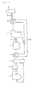
- FIG. 4 is an explanatory drawing showing an example of a conventional smoke exhaust treatment system.
- a combustion exhaust gas discharged from a boiler 1 is heat-exchanged by an air preheater 3 after removing nitrogen oxide by a denitration device 2, and then cooled to, for example, 120°C to 170°C.
- Heat of the exhaust gas passed through the air preheater 3 is taken by a heating medium in a heat recovery device 4 and, after cooled to, for example, 75°C to 110°C, smoke dust in the exhaust gas are removed by a precipitator 5.
- the pressure is further increased by an induced draft fan 6, and then sulfur oxide is removed by a wet-type desulfurization device 7.
- the temperature of the exhaust gas passed through the wet-type smoke exhaust desulfurization device usually decreases to about 40°C to 60°C, resulting in a moisture saturation state.
- a heating medium circulation line 12 using a heat transfer tube is provided between the heat recovery device 4 and the reheater 18, and thus a heating medium is circulated between the heat recovery device 4 and the reheater 18 by a heating medium circulation pump 13 via the heat transfer tube.
- the temperature of the exhaust gas is decreased by the heat recovery device 4 thereby allowing ash in the exhaust gas to adsorb SO 3 and heavy metals, and thus enabling the removal of them together with ash by the precipitator 5. It is also possible to use heat recovered by the heat recovery device 4 for reheating of a moisture saturated gas of an outlet of the wet-type desulfurization device 7, for the purpose of preventing the generation of a white smoke through the funnel 11 (Patent Document 1).
- a CO 2 recovery equipment For the purpose of reducing emissions of CO 2 , it has recently been planned to provide a smoke exhaust treatment system with a CO 2 recovery equipment, and progress has been made in the research and development.
- CO 2 recovery equipment of a CO 2 chemical absorption equipment in which CO 2 is recovered using an aqueous solution of an amine compound such as alkanolamine and the like as an absorbing solution (for example, Patent Document 2).
- Fig. 5 is an explanatory drawing showing an example of a conventional CO 2 chemical absorption equipment by an amine absorbing solution.
- the exhaust gas having a pressure raised by a blower 8 is introduced into the lower portion of an absorption column 25.
- the amine absorbing solution containing CO 2 absorbed therein is stored in the bottom portion of the absorption column 25, introduced into an amine heat exchanger 46 by an absorbing solution circulation pump 28a, heated, for example, from 40°C to 100°C, and then introduced into a regeneration column 26 through a regeneration column amine feed piping 47.
- the CO 2 -rich amine absorbing solution fed through the regeneration column amine feed piping 47 is fed to a regeneration column packed bed 48.
- vapor is fed to the lower portion of the packed bed 48 from a reboiler 30 through a regeneration column vapor feed piping 33,
- CO 2 is eliminated in a gas phase by vapor-liquid contact between the CO 2 -rich amine absorbing solution and vapor. Mist of the amine absorbing solution accompanied with the eliminated CO 2 gas is removed in an upper regeneration column water washing portion 49.
- a regeneration column outlet gas 51 is cooled to 40°C by a regeneration column cooler 52 and condensed water drains are separated by a drum 53, followed by feeding to the regeneration column 26 as washing water 50 of the regeneration column water washing portion by means of a regeneration column wash water pump 54.
- a CO 2 -lean absorbing solution from which CO 2 has been eliminated, is once stored in a tray 55 of the regeneration column lowen portion, and then fed into a reboiler 30 from the lower portion of the reboiler through a reboiler solution feed piping 35.
- the reboiler 30 is provided with a heat transfer tube (not shown), and the absorbing solution is heated to, for example, 120°C to 140°C by passing of a steam 32 through the heat transfer tube.
- the heated absorbing solution generates vapor and the vapor is fed to the regeneration column 26 through the regeneration column vapor piping 33.
- the reboiler 30 is provided with a partition plate 56 and a solution, that has overflown the partition plate 56, is stored in the bottom portion of the regeneration column 26 through a regeneration column solution feed piping 57 and extracted by an amine absorbing solution circulation pump 28b. After decreasing the temperature to, for example, about 40°C by the amine heat exchanger 46, the solution is fed to the absorption column packed bed 40 through the absorption column amine feed piping 41.
- An object of the present invention is to provide an exhaust gas treatment system that effectively use heat recovered from an exhaust gas without any limitation in a CO 2 chemical absorption equipment that requires enormous heat energy, and thus enabling reduction in running cost of the CO 2 chemical absorption equipment.
- a heat recovery device that recovers heat of an exhaust gas discharged from a boiler is provided, and the heat is fed to a CO 2 chemical absorption equipment by an amine absorbing solution and used as a heat source for preheating a regenerating amine absorbing solution to be fed to the reboiler from a regeneration column, thereby raising the temperature of the regenerating amine absorbing solution, and thus enabling a decrease in amount of steam to be fed to the reboiler. Since the above heat source is not used for heating an amine absorbing solution extracted from a CO 2 absorption column, such a problem does not arise: the absorbing solution does not drop in a regeneration column and thus it becomes difficult to circulate the solution. Since the reboiler requires energy that is remarkably more than heat energy recovered from the exhaust gas, limitation on feed of recovered heat for preheating does not arise. Thereby, it becomes possible to configure an exhaust gas treatment system with higher heat efficiency as compared with the prior art.
- a smoke exhaust treatment system comprising a denitration device 2, an air preheater 3, a precipitator 5, an induced draft fan 6, a wet-type desulfurization device 7 and a blower 8 is shown.
- all these devices arrangements are not necessarily indispensable, and addition and deletion of the fan and blower may be made on an exhaust gas passage, or some devices may comprise a system to be by-passed.
- type of the device and the wet-type desulfurization device may be replaced by other type of devices, for example a dry-type desulfurization device and the like.
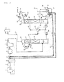
- Fig. 1 is an explanatory drawing showing an Example of an exhaust gas treatment system of the present invention.
- the exhaust treatment system of the present invention and conventional systems shown in Figs. 4 and 5 are different in that a solution feed piping 35 of a reboiler 30 is provided with a heating medium heater 36, and a heating medium circulation line (high temperature side) 12a and a heating medium circulation line (low temperature side) 12b, that configure the heat transfer tube through which a heating medium passes, and a heating medium circulation pump 13 provided between a heat recovery device 4 at an outlet of an air preheater 3 of a boiler 1 and the above-mentioned heating medium heater 36, thereby circulating the heating medium between the heat recovery device 4 and the heating medium heater 36 via the heat transfer tube.
- a solution feed piping 35 of a reboiler 30 is provided with a heating medium heater 36, and a heating medium circulation line (high temperature side) 12a and a heating medium circulation line (low temperature side) 12b, that configure the heat transfer tube
- an exhaust gas from a boiler 1 is introduced into a denitration device 2 and, after removing nitrogen oxide, combustion air to be used in the boiler 1 is heated by the exhaust gas in an air preheater 3.
- the exhaust gas discharged from the air preheater 3 is introduced into a heat recovery device 4 and heat is recovered by a heating medium circulating in the heat recovery device, and thus the exhaust gas is cooled.
- Soot dust in the exhaust discharged from the heat recovery device 4 are precipitated by a precipitator 5, and the exhaust discharged from the precipitator 5 are introduced into a wet-type desulfurization device 7 after raising the pressure by an induced draft fan 6.
- Sulfur oxide is removed by the wet-type desulfurization device 7 and the exhaust gas is delivered to a CO 2 chemical absorption equipment after raising the pressure by a blower 8. Namely, the exhaust gas having a pressure raised by the blower 8 is introduced into the lower portion of an absorption column 25 of the CO 2 chemical absorption equipment.
- the exhaust gas is washed with wash water to be fed through a wash water circulation line 45 in an absorption column water washing portion 42 and, furthermore, mist of the absorbing solution accompanied with the gas is removed and the gas is discharged as a CO 2 -removed gas 27 through a funnel 11 by a fan 10.
- wash water is circulated by an absorption column water washing pump 43.
- the amine absorbing solution containing CO 2 absorbed therein is stored in the bottom portion of an absorption column 25, introduced into an amine heat exchanger 46 by an absorbing solution circulation pump 28a, heated, for example, from 40°C to 100°C, and then introduced into a regeneration column 26 through a regeneration column amine feed piping 47.
- a CO 2 -rich amine absorbing solution to be fed through the regeneration column amine feed piping 47 is fed to the regeneration column packed bed 48.
- vapor is fed to the lower portion of the packed bed 48 from a reboiler 30 through a regeneration column vapor feed piping 33.
- a regeneration column outlet gas 51 is cooled, for example, to 40°C by a regeneration column cooler 52 and condensed drain water are separated by a drum 53, followed by feeding as wash water of the regeneration column water washing portion 49 by means of a regeneration column wash water pump 54.
- a CO 2 -lean absorbing solution from which CO 2 has been eliminated, is once stored in a tray 55 of the regeneration column lower portion, and then fed into a reboiler 30 from the lower portion of the reboiler 30 through a reboiler solution feed piping 35.
- the reboiler 30 is provided with a heat transfer tube (not shown), and the absorbing solution is heated to, for example, 120°C to 140°C by passing of a steam 32 through the heat transfer tube. The heated absorbing solution generates vapor and the vapor is fed to the regeneration column through the regeneration column vapor piping 33.
- the reboiler 30 is provided with a partition plate 56 and a solution that has overflown the partition plate is stored in the bottom portion of the regeneration column 26 through a regeneration column solution feed piping 57 and extracted by an amine absorbing solution circulation pump 28b. After decreasing the temperature to, for example, about 40°C by the amine heat exchanger 46, the solution is fed to the absorption column packed bed 40 through the absorption column amine feed piping 41.
- a heating medium is circulated between a heating medium heater 36 provided in a reboiler solution feed piping 35 and a heat recovery device 4 through heating medium circulation lines 12a, 12b by a heating medium circulation pump 13, and a regenerated amine solution passing through the reboiler solution feed piping 35 is heated by a heating medium having a temperature raised due to heat-changing by a heat recovery device 4.
- a heating medium having a temperature raised due to heat-changing by a heat recovery device 4.
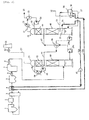
- FIG. 2 Another Example of the present invention is shown in Fig. 2 .
- a basic configuration of Fig. 2 is the same as that of Fig. 1 , except for the following configuration of Fig. 2 in which an absorbing solution stored in a tray 55 provided at the lower portion of a regeneration column 26 is delivered to a heat recovery device 4 that recovers heat by an exhaust gas from a boiler 1 by a regenerating amine absorbing solution circulation pump 15 provided in a heating medium circulation line (low temperature side) 12b, and the absorbing solution heated to high temperature by heat recovery is delivered to a reboiler 30 through a heating medium circulation line 12a.
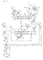
- FIG. 3 Comparative Example to Examples shown in Figs. 1 and 2 is shown in Fig. 3 .
- a basic configuration of the system of Fig. 3 is the same as those of Fig. at and Fig. 2 , except for the following configuration of Fig. 3 in which an amine absorbing solution extracted from the bottom of a regeneration column 26 is delivered to an amine solution heat exchanger 46 by a circulation pump 28b after passing through a heat recovery device 4 that recovers heat by an exhaust gas from a boiler 1, and thus the amine absorbing solution to be fed to an absorption column 25 is preheated.
Landscapes
- Engineering & Computer Science (AREA)
- Chemical & Material Sciences (AREA)
- Oil, Petroleum & Natural Gas (AREA)
- General Engineering & Computer Science (AREA)
- Analytical Chemistry (AREA)
- General Chemical & Material Sciences (AREA)
- Mechanical Engineering (AREA)
- Chemical Kinetics & Catalysis (AREA)
- Health & Medical Sciences (AREA)
- Biomedical Technology (AREA)
- Environmental & Geological Engineering (AREA)
- Gas Separation By Absorption (AREA)
- Treating Waste Gases (AREA)
- Chimneys And Flues (AREA)
Priority Applications (1)
| Application Number | Priority Date | Filing Date | Title |
|---|---|---|---|
| PL11771994T PL2561919T3 (pl) | 2010-04-20 | 2011-04-19 | Układ do obróbki gazów spalinowych zaopatrzony w urządzenie do chemisorpcji dwutlenku węgla |
Applications Claiming Priority (2)
| Application Number | Priority Date | Filing Date | Title |
|---|---|---|---|
| JP2010096844A JP5686987B2 (ja) | 2010-04-20 | 2010-04-20 | 二酸化炭素化学吸収設備を備えた排ガス処理システム |
| PCT/JP2011/059597 WO2011132659A1 (fr) | 2010-04-20 | 2011-04-19 | Système de traitement des gaz d'échappement muni d'un équipement d'absorption chimique du dioxyde de carbone |
Publications (3)
| Publication Number | Publication Date |
|---|---|
| EP2561919A1 true EP2561919A1 (fr) | 2013-02-27 |
| EP2561919A4 EP2561919A4 (fr) | 2014-08-27 |
| EP2561919B1 EP2561919B1 (fr) | 2017-07-19 |
Family
ID=44834178
Family Applications (1)
| Application Number | Title | Priority Date | Filing Date |
|---|---|---|---|
| EP11771994.8A Active EP2561919B1 (fr) | 2010-04-20 | 2011-04-19 | Système de traitement des gaz d'échappement muni d'un équipement d'absorption chimique du dioxyde de carbone |
Country Status (8)
| Country | Link |
|---|---|
| US (1) | US8741034B2 (fr) |
| EP (1) | EP2561919B1 (fr) |
| JP (1) | JP5686987B2 (fr) |
| CN (1) | CN102933284A (fr) |
| CA (1) | CA2796745C (fr) |
| ES (1) | ES2642797T3 (fr) |
| PL (1) | PL2561919T3 (fr) |
| WO (1) | WO2011132659A1 (fr) |
Cited By (2)
| Publication number | Priority date | Publication date | Assignee | Title |
|---|---|---|---|---|
| CN106076114A (zh) * | 2016-08-12 | 2016-11-09 | 王涛 | 一种烟气处理系统及方法 |
| EP4353676A1 (fr) * | 2022-10-14 | 2024-04-17 | L'air Liquide, Societe Anonyme Pour L'etude Et L'exploitation Des Procedes Georges Claude | Installation et procédé de production d'un produit de gaz de synthèse appauvri en dioxyde de carbone par reformage à la vapeur |
Families Citing this family (17)
| Publication number | Priority date | Publication date | Assignee | Title |
|---|---|---|---|---|
| EP2481466A1 (fr) * | 2011-01-31 | 2012-08-01 | Siemens Aktiengesellschaft | Dispositif et procédé de nettoyage d'un produit d'une installation de processus contaminé par de la nitrosamine |
| JP5632787B2 (ja) * | 2011-04-05 | 2014-11-26 | 株式会社日立製作所 | 超臨界水を用いた反応プロセス |
| KR101292084B1 (ko) | 2013-03-11 | 2013-08-01 | 제동일 | 생체 아민을 포함하는 이산화탄소 흡수제 및 이를 이용한 배가스 중의 이산화탄소 제거방법 |
| US10375901B2 (en) | 2014-12-09 | 2019-08-13 | Mtd Products Inc | Blower/vacuum |
| JP6576288B2 (ja) * | 2016-04-01 | 2019-09-18 | 日鉄エンジニアリング株式会社 | 二酸化炭素ガスの回収装置、及び、二酸化炭素ガスの製造方法 |
| CN107042054A (zh) * | 2017-03-27 | 2017-08-15 | 南京工业大学 | 一种醛类废气的处理方法 |
| JP7668167B2 (ja) * | 2021-06-18 | 2025-04-24 | 一般財団法人電力中央研究所 | 排ガス処理設備、発電設備 |
| KR102631336B1 (ko) * | 2021-08-27 | 2024-02-01 | 한국에너지기술연구원 | 수소 및 이산화탄소의 분리회수 시스템 |
| JP7797161B2 (ja) * | 2021-10-21 | 2026-01-13 | 三菱重工業株式会社 | Co2回収システム及びco2回収方法 |
| US12030013B2 (en) | 2021-10-22 | 2024-07-09 | Saudi Arabian Oil Company | Process for capturing CO2 from a mobile source using exhaust heat |
| CN113828120A (zh) * | 2021-11-01 | 2021-12-24 | 中国船舶重工集团公司第七一一研究所 | 一种低能耗船舶柴油机烟气co2捕集系统 |
| US11484825B1 (en) * | 2021-12-20 | 2022-11-01 | Next Carbon Solutions, Llc | Devices, systems, facilities and processes for carbon capture optimization in industrial facilities |
| CN114712990B (zh) * | 2022-03-17 | 2023-08-08 | 中国华能集团清洁能源技术研究院有限公司 | 一种co2再生装置及工艺方法 |
| CA3261291A1 (fr) * | 2022-07-29 | 2024-02-01 | Carbon Clean Solutions Limited | Procédé et système pour l'élimination de dioxyde de carbone à partir de solvants de capture de carbone à l'aide de chaleur provenant d'un gaz |
| JP7309983B1 (ja) | 2022-08-08 | 2023-07-18 | 株式会社タクマ | 二酸化炭素回収装置、及び二酸化炭素回収方法 |
| DK182182B1 (en) * | 2024-04-16 | 2025-10-24 | Everllence Filial Af Everllence Se Tyskland | Method and large two-stroke uniflow scavenged internal combustion engine configured for carbon dioxide capture |
| CN118437116B (zh) * | 2024-05-13 | 2026-03-03 | 中国华能集团清洁能源技术研究院有限公司 | 碳捕集系统、垃圾焚烧发电系统及碳捕集作业方法 |
Family Cites Families (15)
| Publication number | Priority date | Publication date | Assignee | Title |
|---|---|---|---|---|
| US4514379A (en) * | 1983-06-28 | 1985-04-30 | Union Oil Company Of California | Catalytic process for converting 2-oxazolidinones to their corresponding alkanolamines |
| JPH0731834A (ja) * | 1993-06-28 | 1995-02-03 | Mitsubishi Heavy Ind Ltd | 吸収液の再生方法 |
| NO180520C (no) * | 1994-02-15 | 1997-05-07 | Kvaerner Asa | Fremgangsmåte til fjerning av karbondioksid fra forbrenningsgasser |
| JP3486220B2 (ja) | 1994-03-08 | 2004-01-13 | バブコック日立株式会社 | 燃焼排ガス浄化方法および装置 |
| US6174506B1 (en) * | 1999-06-10 | 2001-01-16 | Praxair Technology, Inc. | Carbon dioxide recovery from an oxygen containing mixture |
| JP3969949B2 (ja) | 2000-10-25 | 2007-09-05 | 関西電力株式会社 | アミン回収方法及び装置並びにこれを備えた脱炭酸ガス装置 |
| CN1137753C (zh) * | 2000-12-19 | 2004-02-11 | 中国冶金建设集团鞍山焦化耐火材料设计研究总院 | 生物气中co2、h2s的净化工艺 |
| JP4231735B2 (ja) | 2003-02-04 | 2009-03-04 | 新日本製鐵株式会社 | 二酸化炭素の分離回収方法および装置 |
| JP4875303B2 (ja) * | 2005-02-07 | 2012-02-15 | 三菱重工業株式会社 | 二酸化炭素回収システム、これを用いた発電システムおよびこれら方法 |
| NO326645B1 (no) * | 2005-06-28 | 2009-01-26 | Ntnu Technology Transfer As | Fremgangsmate og apparatur for a fjerne og gjenvinne sure gasser, CO2 og/eller H2S. |
| US7976803B2 (en) * | 2005-08-16 | 2011-07-12 | Co2Crc Technologies Pty Ltd. | Plant and process for removing carbon dioxide from gas streams |
| JP4795991B2 (ja) * | 2007-02-27 | 2011-10-19 | 三菱重工業株式会社 | Co2回収装置及びco2回収装置における固形分取出し方法 |
| US8192530B2 (en) * | 2007-12-13 | 2012-06-05 | Alstom Technology Ltd | System and method for regeneration of an absorbent solution |
| JP2009247932A (ja) * | 2008-04-02 | 2009-10-29 | Chiyoda Kako Kensetsu Kk | 排ガス熱源を利用した二酸化炭素の除去方法 |
| JP5558036B2 (ja) * | 2008-09-04 | 2014-07-23 | 株式会社東芝 | 二酸化炭素回収型汽力発電システム |
-
2010
- 2010-04-20 JP JP2010096844A patent/JP5686987B2/ja active Active
-
2011
- 2011-04-19 WO PCT/JP2011/059597 patent/WO2011132659A1/fr not_active Ceased
- 2011-04-19 CN CN2011800266160A patent/CN102933284A/zh active Pending
- 2011-04-19 PL PL11771994T patent/PL2561919T3/pl unknown
- 2011-04-19 EP EP11771994.8A patent/EP2561919B1/fr active Active
- 2011-04-19 ES ES11771994.8T patent/ES2642797T3/es active Active
- 2011-04-19 CA CA2796745A patent/CA2796745C/fr active Active
- 2011-04-19 US US13/641,786 patent/US8741034B2/en active Active
Cited By (3)
| Publication number | Priority date | Publication date | Assignee | Title |
|---|---|---|---|---|
| CN106076114A (zh) * | 2016-08-12 | 2016-11-09 | 王涛 | 一种烟气处理系统及方法 |
| CN106076114B (zh) * | 2016-08-12 | 2019-06-14 | 王涛 | 一种烟气处理系统及方法 |
| EP4353676A1 (fr) * | 2022-10-14 | 2024-04-17 | L'air Liquide, Societe Anonyme Pour L'etude Et L'exploitation Des Procedes Georges Claude | Installation et procédé de production d'un produit de gaz de synthèse appauvri en dioxyde de carbone par reformage à la vapeur |
Also Published As
| Publication number | Publication date |
|---|---|
| CA2796745A1 (fr) | 2011-10-27 |
| ES2642797T3 (es) | 2017-11-20 |
| WO2011132659A1 (fr) | 2011-10-27 |
| JP5686987B2 (ja) | 2015-03-18 |
| PL2561919T3 (pl) | 2018-01-31 |
| EP2561919A4 (fr) | 2014-08-27 |
| CN102933284A (zh) | 2013-02-13 |
| US8741034B2 (en) | 2014-06-03 |
| CA2796745C (fr) | 2017-11-21 |
| EP2561919B1 (fr) | 2017-07-19 |
| JP2011224472A (ja) | 2011-11-10 |
| US20130052096A1 (en) | 2013-02-28 |
Similar Documents
| Publication | Publication Date | Title |
|---|---|---|
| CA2796745C (fr) | Systeme de traitement des gaz d'echappement muni d'un equipement d'absorption chimique du dioxyde de carbone | |
| JP6072055B2 (ja) | 排ガス処理システム及び方法 | |
| US9399939B2 (en) | Combustion exhaust gas treatment system and method of treating combustion exhaust gas | |
| JP5416679B2 (ja) | 排ガス処理方法と装置 | |
| US9138677B2 (en) | Ammonia stripper for a carbon capture system for reduction of energy consumption | |
| JP5976812B2 (ja) | 排ガス処理システム | |
| JP5457543B2 (ja) | 二酸化炭素除去装置を備えた排ガス処理システム | |
| JP6232134B2 (ja) | 排気ガスの廃熱回収および白煙低減方法と装置 | |
| JP5738137B2 (ja) | Co2回収装置およびco2回収方法 | |
| WO2011132660A1 (fr) | Système de traitement de gaz d'échappement ayant un dispositif d'élimination de dioxyde de carbone | |
| KR20130023484A (ko) | 에너지 효율이 증대된 발전소 이산화탄소 포집장치 및 포집방법 | |
| JP5369048B2 (ja) | 二酸化炭素化学吸収設備を有する排ガス処理システムおよび方法 | |
| JP2011194292A (ja) | 排ガス処理方法および装置 | |
| JP6173734B2 (ja) | 排ガス処理システム |
Legal Events
| Date | Code | Title | Description |
|---|---|---|---|
| PUAI | Public reference made under article 153(3) epc to a published international application that has entered the european phase |
Free format text: ORIGINAL CODE: 0009012 |
|
| 17P | Request for examination filed |
Effective date: 20121114 |
|
| AK | Designated contracting states |
Kind code of ref document: A1 Designated state(s): AL AT BE BG CH CY CZ DE DK EE ES FI FR GB GR HR HU IE IS IT LI LT LU LV MC MK MT NL NO PL PT RO RS SE SI SK SM TR |
|
| DAX | Request for extension of the european patent (deleted) | ||
| A4 | Supplementary search report drawn up and despatched |
Effective date: 20140728 |
|
| RIC1 | Information provided on ipc code assigned before grant |
Ipc: F23J 15/00 20060101ALI20140722BHEP Ipc: B01D 53/62 20060101AFI20140722BHEP Ipc: B01D 53/14 20060101ALI20140722BHEP |
|
| RAP1 | Party data changed (applicant data changed or rights of an application transferred) |
Owner name: MITSUBISHI HITACHI POWER SYSTEMS, LTD. |
|
| RAP1 | Party data changed (applicant data changed or rights of an application transferred) |
Owner name: MITSUBISHI HITACHI POWER SYSTEMS, LTD. |
|
| 17Q | First examination report despatched |
Effective date: 20150819 |
|
| GRAP | Despatch of communication of intention to grant a patent |
Free format text: ORIGINAL CODE: EPIDOSNIGR1 |
|
| STAA | Information on the status of an ep patent application or granted ep patent |
Free format text: STATUS: GRANT OF PATENT IS INTENDED |
|
| INTG | Intention to grant announced |
Effective date: 20170130 |
|
| GRAS | Grant fee paid |
Free format text: ORIGINAL CODE: EPIDOSNIGR3 |
|
| GRAA | (expected) grant |
Free format text: ORIGINAL CODE: 0009210 |
|
| STAA | Information on the status of an ep patent application or granted ep patent |
Free format text: STATUS: THE PATENT HAS BEEN GRANTED |
|
| AK | Designated contracting states |
Kind code of ref document: B1 Designated state(s): AL AT BE BG CH CY CZ DE DK EE ES FI FR GB GR HR HU IE IS IT LI LT LU LV MC MK MT NL NO PL PT RO RS SE SI SK SM TR |
|
| REG | Reference to a national code |
Ref country code: GB Ref legal event code: FG4D |
|
| REG | Reference to a national code |
Ref country code: CH Ref legal event code: EP |
|
| REG | Reference to a national code |
Ref country code: IE Ref legal event code: FG4D |
|
| REG | Reference to a national code |
Ref country code: AT Ref legal event code: REF Ref document number: 909843 Country of ref document: AT Kind code of ref document: T Effective date: 20170815 |
|
| REG | Reference to a national code |
Ref country code: DE Ref legal event code: R096 Ref document number: 602011039751 Country of ref document: DE |
|
| REG | Reference to a national code |
Ref country code: SE Ref legal event code: TRGR |
|
| REG | Reference to a national code |
Ref country code: ES Ref legal event code: FG2A Ref document number: 2642797 Country of ref document: ES Kind code of ref document: T3 Effective date: 20171120 |
|
| REG | Reference to a national code |
Ref country code: NL Ref legal event code: MP Effective date: 20170719 |
|
| REG | Reference to a national code |
Ref country code: LT Ref legal event code: MG4D |
|
| REG | Reference to a national code |
Ref country code: AT Ref legal event code: MK05 Ref document number: 909843 Country of ref document: AT Kind code of ref document: T Effective date: 20170719 |
|
| REG | Reference to a national code |
Ref country code: NO Ref legal event code: T2 Effective date: 20170719 |
|
| PG25 | Lapsed in a contracting state [announced via postgrant information from national office to epo] |
Ref country code: NL Free format text: LAPSE BECAUSE OF FAILURE TO SUBMIT A TRANSLATION OF THE DESCRIPTION OR TO PAY THE FEE WITHIN THE PRESCRIBED TIME-LIMIT Effective date: 20170719 Ref country code: AT Free format text: LAPSE BECAUSE OF FAILURE TO SUBMIT A TRANSLATION OF THE DESCRIPTION OR TO PAY THE FEE WITHIN THE PRESCRIBED TIME-LIMIT Effective date: 20170719 Ref country code: LT Free format text: LAPSE BECAUSE OF FAILURE TO SUBMIT A TRANSLATION OF THE DESCRIPTION OR TO PAY THE FEE WITHIN THE PRESCRIBED TIME-LIMIT Effective date: 20170719 Ref country code: FI Free format text: LAPSE BECAUSE OF FAILURE TO SUBMIT A TRANSLATION OF THE DESCRIPTION OR TO PAY THE FEE WITHIN THE PRESCRIBED TIME-LIMIT Effective date: 20170719 Ref country code: HR Free format text: LAPSE BECAUSE OF FAILURE TO SUBMIT A TRANSLATION OF THE DESCRIPTION OR TO PAY THE FEE WITHIN THE PRESCRIBED TIME-LIMIT Effective date: 20170719 |
|
| PG25 | Lapsed in a contracting state [announced via postgrant information from national office to epo] |
Ref country code: GR Free format text: LAPSE BECAUSE OF FAILURE TO SUBMIT A TRANSLATION OF THE DESCRIPTION OR TO PAY THE FEE WITHIN THE PRESCRIBED TIME-LIMIT Effective date: 20171020 Ref country code: LV Free format text: LAPSE BECAUSE OF FAILURE TO SUBMIT A TRANSLATION OF THE DESCRIPTION OR TO PAY THE FEE WITHIN THE PRESCRIBED TIME-LIMIT Effective date: 20170719 Ref country code: RS Free format text: LAPSE BECAUSE OF FAILURE TO SUBMIT A TRANSLATION OF THE DESCRIPTION OR TO PAY THE FEE WITHIN THE PRESCRIBED TIME-LIMIT Effective date: 20170719 Ref country code: IS Free format text: LAPSE BECAUSE OF FAILURE TO SUBMIT A TRANSLATION OF THE DESCRIPTION OR TO PAY THE FEE WITHIN THE PRESCRIBED TIME-LIMIT Effective date: 20171119 Ref country code: BG Free format text: LAPSE BECAUSE OF FAILURE TO SUBMIT A TRANSLATION OF THE DESCRIPTION OR TO PAY THE FEE WITHIN THE PRESCRIBED TIME-LIMIT Effective date: 20171019 |
|
| REG | Reference to a national code |
Ref country code: FR Ref legal event code: PLFP Year of fee payment: 8 |
|
| REG | Reference to a national code |
Ref country code: DE Ref legal event code: R097 Ref document number: 602011039751 Country of ref document: DE |
|
| PG25 | Lapsed in a contracting state [announced via postgrant information from national office to epo] |
Ref country code: CZ Free format text: LAPSE BECAUSE OF FAILURE TO SUBMIT A TRANSLATION OF THE DESCRIPTION OR TO PAY THE FEE WITHIN THE PRESCRIBED TIME-LIMIT Effective date: 20170719 Ref country code: DK Free format text: LAPSE BECAUSE OF FAILURE TO SUBMIT A TRANSLATION OF THE DESCRIPTION OR TO PAY THE FEE WITHIN THE PRESCRIBED TIME-LIMIT Effective date: 20170719 Ref country code: RO Free format text: LAPSE BECAUSE OF FAILURE TO SUBMIT A TRANSLATION OF THE DESCRIPTION OR TO PAY THE FEE WITHIN THE PRESCRIBED TIME-LIMIT Effective date: 20170719 |
|
| PLBE | No opposition filed within time limit |
Free format text: ORIGINAL CODE: 0009261 |
|
| STAA | Information on the status of an ep patent application or granted ep patent |
Free format text: STATUS: NO OPPOSITION FILED WITHIN TIME LIMIT |
|
| PG25 | Lapsed in a contracting state [announced via postgrant information from national office to epo] |
Ref country code: SM Free format text: LAPSE BECAUSE OF FAILURE TO SUBMIT A TRANSLATION OF THE DESCRIPTION OR TO PAY THE FEE WITHIN THE PRESCRIBED TIME-LIMIT Effective date: 20170719 Ref country code: IT Free format text: LAPSE BECAUSE OF FAILURE TO SUBMIT A TRANSLATION OF THE DESCRIPTION OR TO PAY THE FEE WITHIN THE PRESCRIBED TIME-LIMIT Effective date: 20170719 Ref country code: EE Free format text: LAPSE BECAUSE OF FAILURE TO SUBMIT A TRANSLATION OF THE DESCRIPTION OR TO PAY THE FEE WITHIN THE PRESCRIBED TIME-LIMIT Effective date: 20170719 Ref country code: SK Free format text: LAPSE BECAUSE OF FAILURE TO SUBMIT A TRANSLATION OF THE DESCRIPTION OR TO PAY THE FEE WITHIN THE PRESCRIBED TIME-LIMIT Effective date: 20170719 |
|
| 26N | No opposition filed |
Effective date: 20180420 |
|
| PG25 | Lapsed in a contracting state [announced via postgrant information from national office to epo] |
Ref country code: SI Free format text: LAPSE BECAUSE OF FAILURE TO SUBMIT A TRANSLATION OF THE DESCRIPTION OR TO PAY THE FEE WITHIN THE PRESCRIBED TIME-LIMIT Effective date: 20170719 |
|
| PG25 | Lapsed in a contracting state [announced via postgrant information from national office to epo] |
Ref country code: MC Free format text: LAPSE BECAUSE OF FAILURE TO SUBMIT A TRANSLATION OF THE DESCRIPTION OR TO PAY THE FEE WITHIN THE PRESCRIBED TIME-LIMIT Effective date: 20170719 |
|
| REG | Reference to a national code |
Ref country code: CH Ref legal event code: PL |
|
| REG | Reference to a national code |
Ref country code: BE Ref legal event code: MM Effective date: 20180430 |
|
| REG | Reference to a national code |
Ref country code: IE Ref legal event code: MM4A |
|
| PG25 | Lapsed in a contracting state [announced via postgrant information from national office to epo] |
Ref country code: LU Free format text: LAPSE BECAUSE OF NON-PAYMENT OF DUE FEES Effective date: 20180419 |
|
| PG25 | Lapsed in a contracting state [announced via postgrant information from national office to epo] |
Ref country code: BE Free format text: LAPSE BECAUSE OF NON-PAYMENT OF DUE FEES Effective date: 20180430 Ref country code: LI Free format text: LAPSE BECAUSE OF NON-PAYMENT OF DUE FEES Effective date: 20180430 Ref country code: CH Free format text: LAPSE BECAUSE OF NON-PAYMENT OF DUE FEES Effective date: 20180430 |
|
| PG25 | Lapsed in a contracting state [announced via postgrant information from national office to epo] |
Ref country code: IE Free format text: LAPSE BECAUSE OF NON-PAYMENT OF DUE FEES Effective date: 20180419 |
|
| PG25 | Lapsed in a contracting state [announced via postgrant information from national office to epo] |
Ref country code: MT Free format text: LAPSE BECAUSE OF NON-PAYMENT OF DUE FEES Effective date: 20180419 |
|
| PG25 | Lapsed in a contracting state [announced via postgrant information from national office to epo] |
Ref country code: TR Free format text: LAPSE BECAUSE OF FAILURE TO SUBMIT A TRANSLATION OF THE DESCRIPTION OR TO PAY THE FEE WITHIN THE PRESCRIBED TIME-LIMIT Effective date: 20170719 |
|
| PG25 | Lapsed in a contracting state [announced via postgrant information from national office to epo] |
Ref country code: HU Free format text: LAPSE BECAUSE OF FAILURE TO SUBMIT A TRANSLATION OF THE DESCRIPTION OR TO PAY THE FEE WITHIN THE PRESCRIBED TIME-LIMIT; INVALID AB INITIO Effective date: 20110419 Ref country code: PT Free format text: LAPSE BECAUSE OF FAILURE TO SUBMIT A TRANSLATION OF THE DESCRIPTION OR TO PAY THE FEE WITHIN THE PRESCRIBED TIME-LIMIT Effective date: 20170719 |
|
| PG25 | Lapsed in a contracting state [announced via postgrant information from national office to epo] |
Ref country code: CY Free format text: LAPSE BECAUSE OF FAILURE TO SUBMIT A TRANSLATION OF THE DESCRIPTION OR TO PAY THE FEE WITHIN THE PRESCRIBED TIME-LIMIT Effective date: 20170719 Ref country code: MK Free format text: LAPSE BECAUSE OF NON-PAYMENT OF DUE FEES Effective date: 20170719 |
|
| PG25 | Lapsed in a contracting state [announced via postgrant information from national office to epo] |
Ref country code: AL Free format text: LAPSE BECAUSE OF FAILURE TO SUBMIT A TRANSLATION OF THE DESCRIPTION OR TO PAY THE FEE WITHIN THE PRESCRIBED TIME-LIMIT Effective date: 20170719 |
|
| REG | Reference to a national code |
Ref country code: DE Ref legal event code: R082 Ref document number: 602011039751 Country of ref document: DE Representative=s name: PAGE, WHITE & FARRER GERMANY LLP, DE Ref country code: DE Ref legal event code: R081 Ref document number: 602011039751 Country of ref document: DE Owner name: MITSUBISHI POWER, LTD., JP Free format text: FORMER OWNER: MITSUBISHI HITACHI POWER SYSTEMS, LTD., YOKOHAMA, JP |
|
| REG | Reference to a national code |
Ref country code: NO Ref legal event code: CHAD Owner name: MITSUBISHI POWER, JP |
|
| REG | Reference to a national code |
Ref country code: ES Ref legal event code: PC2A Owner name: MITSUBISHI POWER, LTD. Effective date: 20210421 |
|
| PGFP | Annual fee paid to national office [announced via postgrant information from national office to epo] |
Ref country code: DE Payment date: 20250305 Year of fee payment: 15 |
|
| PGFP | Annual fee paid to national office [announced via postgrant information from national office to epo] |
Ref country code: ES Payment date: 20250506 Year of fee payment: 15 |
|
| PGFP | Annual fee paid to national office [announced via postgrant information from national office to epo] |
Ref country code: NO Payment date: 20250409 Year of fee payment: 15 |
|
| REG | Reference to a national code |
Ref country code: DE Ref legal event code: R082 Ref document number: 602011039751 Country of ref document: DE Representative=s name: WESTPHAL, MUSSGNUG & PARTNER PATENTANWAELTE MI, DE |
|
| PGFP | Annual fee paid to national office [announced via postgrant information from national office to epo] |
Ref country code: SE Payment date: 20260312 Year of fee payment: 16 |
|
| PGFP | Annual fee paid to national office [announced via postgrant information from national office to epo] |
Ref country code: GB Payment date: 20260313 Year of fee payment: 16 |
|
| PGFP | Annual fee paid to national office [announced via postgrant information from national office to epo] |
Ref country code: FR Payment date: 20260309 Year of fee payment: 16 |
|
| PGFP | Annual fee paid to national office [announced via postgrant information from national office to epo] |
Ref country code: PL Payment date: 20260312 Year of fee payment: 16 |