EP2562013B1 - Ensemble d'attelage - Google Patents
Ensemble d'attelage Download PDFInfo
- Publication number
- EP2562013B1 EP2562013B1 EP12181885.0A EP12181885A EP2562013B1 EP 2562013 B1 EP2562013 B1 EP 2562013B1 EP 12181885 A EP12181885 A EP 12181885A EP 2562013 B1 EP2562013 B1 EP 2562013B1
- Authority
- EP
- European Patent Office
- Prior art keywords
- receiver
- drawbar
- hitch
- arm
- attachment
- Prior art date
- Legal status (The legal status is an assumption and is not a legal conclusion. Google has not performed a legal analysis and makes no representation as to the accuracy of the status listed.)
- Not-in-force
Links
Images

Classifications
-
- B—PERFORMING OPERATIONS; TRANSPORTING
- B60—VEHICLES IN GENERAL
- B60D—VEHICLE CONNECTIONS
- B60D1/00—Traction couplings; Hitches; Draw-gear; Towing devices
- B60D1/48—Traction couplings; Hitches; Draw-gear; Towing devices characterised by the mounting
- B60D1/52—Traction couplings; Hitches; Draw-gear; Towing devices characterised by the mounting removably mounted
-
- B—PERFORMING OPERATIONS; TRANSPORTING
- B60—VEHICLES IN GENERAL
- B60D—VEHICLE CONNECTIONS
- B60D1/00—Traction couplings; Hitches; Draw-gear; Towing devices
- B60D1/14—Draw-gear or towing devices characterised by their type
- B60D1/145—Draw-gear or towing devices characterised by their type consisting of an elongated single bar or tube
- B60D1/155—Draw-gear or towing devices characterised by their type consisting of an elongated single bar or tube comprising telescopic or foldable parts
Definitions
- the present invention relates to motor vehicle accessories, and particularly to a receiver hitch assembly having a vertically oriented receiver, the receiver being concealed by the rear bumper of the towing vehicle when the drawbar is removed.
- trailer hitches and/or rearward-mounted attachments for removably mounting and/or carrying various articles on a motor vehicle are popular accessories on many motor vehicles.
- An increasingly popular version of such hitches or attachments is the so-called "receiver hitch,” in which a tubular (generally square cross-section) socket or receptacle, known as a receiver, is permanently mounted on the rear of the towing vehicle, and the drawbar with its hitch ball or other trailer attachment is removably installed to the receiver when it is necessary to tow a trailer or mount some external structure to the receiver hitch.
- a receiver hitch is described in EP 2 236 322 A1 which discloses the preamble of claim 1. While such hitches are quite common on larger motor vehicles, such as pickup trucks, larger vans, and sport utility vehicles, they have become increasingly popular installations on standard automobiles and smaller cars as well.
- One solution has been to cut away a portion of the bumper for clearance, but this is obviously unsightly and not many vehicle owners are willing to damage their vehicles in this manner.
- the permanent portion of the hitch assembly i.e., the mounting structure that attaches to the vehicle frame and the receiver that extends from the mounting structure, is mounted in such a manner as to provide clearance from the bumper for the drawbar when installed, the result is an unsightly protrusion of the receiver from beneath the rear bumper of the vehicle, even when the drawbar has been removed from the receiver.
- the inventive receiver hitch assembly as disclosed in claim 1 has a permanently mounted receptacle beneath the rear of the towing vehicle.
- the receiver or receptacle is mounted in such a manner as to be concealed by the rear bumper valance or other structure of the towing vehicle once installed thereon.
- the drawbar assembly has a receiver attachment end that fits closely within the receiver, and a hitch pin passes laterally through the receiver and drawbar to secure the drawbar end within the receiver. Both the receiver and the receiver attachment end of the drawbar are oriented vertically when installed to the towing vehicle.
- the drawbar has a rearward extending horizontal portion that passes beneath the rear bumper valance and/or other vehicle structure when installed on the towing vehicle, and an upwardly extending arm opposite the drawbar attachment end thereof. Another horizontal component extends rearward from the upper end of the upwardly extending arm, generally coplanar with the center of the receiver when the drawbar is installed thereto.
- a hitch ball arm comprising an elongate heavy metal plate extends rearward from the rear of the drawbar assembly, and a hitch ball is bolted to the rearward end of the arm.
- the two vertical portions of the drawbar, with the horizontal portion therebetween, define a squared, generally U-shaped configuration for the drawbar.
- the horizontal portion of the drawbar may comprise two separate components, one telescoping within the other to allow the spacing between the two vertical portions of the drawbar to be adjusted as desired. This provides adjustment for clearance for different dimensions of bumper valances or structures on various towing vehicles, as well as positioning the hitch ball forward or rearward for clearance, load distribution, or other reasons.
- the receiver hitch assembly has a receiver with a vertical drawbar receptacle.
- the drawbar has a receiver attachment end that is oriented vertically when installed in the receiver.
- the receiver is permanently attached beneath the rear of the vehicle and is concealed, so that only the drawbar is visible when the drawbar is installed to the receiver.
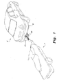
- Fig. 1 of the drawings provides an environmental perspective view of the general configuration and installation of a first embodiment of the receiver hitch assembly 10, shown installed upon a towing vehicle V for towing a trailer T.
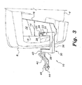
- Figs. 2 and 3 provide detailed perspective views of the receiver hitch assembly 10 installed upon a towing vehicle V.
- the receiver hitch assembly 10 includes a receiver mounting member 12 comprising a solid, unbroken, rigid plate that is permanently mounted beneath the rear of the towing vehicle V, generally as shown in Fig. 3 .
- the mounting member or plate 12 has a longitudinal span 14 defined by its mutually opposed forward and rearward edges 16 and 18, the receiver 20 depending beneath the receiver mounting member 12 adjacent the rearward edge 18 thereof.
- the receiver 20 comprises a tubular member having a rectangular cross section, the drawbar attachment receptacle 22 being oriented substantially vertically when installed upon the towing vehicle V.
- a hitch pin passage 24 is disposed laterally and substantially centrally thereacross, and a hitch pin 26 is removably installed through the hitch pin passage 24 to secure the drawbar assembly thereto.
- a retaining clip 28 secures removably through a passage in the end of the hitch pin 26 to retain the hitch pin in the receiver 20.
- the drawbar 30 has a generally U-shaped forward portion to provide clearance from the rear bumper B of the towing vehicle V, generally as shown in each of the drawings.
- the drawbar 30 includes a receiver attachment end 32 comprising a square tube dimensioned to fit closely and concentrically within the receptacle 22 of the receiver 20, as shown in Fig. 3 of the drawings, the receiver attachment end 32 being substantially vertically oriented when installed when installed in the receiver 20 due to the concentric assembly of the two components.
- a hitch pin passage 34 is formed laterally through the distal end of the receiver attachment end 32 of the drawbar 30, the hitch pin passage 34 of the receiver attachment end 32 being aligned concentrically with the hitch pin passage 24 of the receiver 20 when the drawbar 30 is installed thereto.
- the hitch pin 26 passes through both hitch pin passages 24 and 34 to secure the drawbar 30 to the receiver 20.
- a drawbar arm 36 extends from the end of the receiver attachment end 32 of the drawbar 30, and is oriented substantially normal to the receiver attachment end 32. This orients the drawbar arm substantially horizontally when the drawbar 30 is installed to the receiver 20.
- a riser 38 extends upwardly from the drawbar arm 36 opposite the receiver attachment end 32 of the drawbar 30 and substantially parallel thereto.
- a hitch bar attachment arm 40 extends from the riser 38, opposite the drawbar arm 36 and substantially parallel and coplanar with the drawbar arm 36.
- the receiver attachment end 32, drawbar arm 36, riser 38, and hitch bar attachment arm 40 are each preferably formed of square tubing.
- the receiver attachment end 32, drawbar arm 36, and riser 38 define a rectangular, generally U-shaped configuration to provide clearance from the bumper B of the towing vehicle V when installed thereon, generally as shown in Figs. 1 and 3 of the drawings.
- a hitch bar 42 formed of a solid plate of thick metal extends rearward from the hitch bar attachment arm 40, opposite the arm 40 attachment to the riser 38.
- the end of the hitch bar attachment arm 40 is preferably beveled, and the attachment portion of the hitch bar 42 has a corresponding slope, as shown in the drawings.
- the slope of the attachment portion of the hitch bar 40 results in the rearward end 44 of the hitch bar 42, i.e., the end or portion having the hitch ball 46 attached thereto, having a downward and rearward offset, as shown in the various drawings.
- the hitch ball 46 is conventional, having a threaded bolt or stud that passes therethrough and through a passage (not shown) through the hitch bar 42, and a nut secures the bolt or stud and hitch ball 46 to the hitch bar.
- the ball 46 may be removed and interchanged with different ball diameters, as needed.
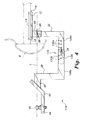
- Fig. 4 of the drawings provides a right side elevation view of an alternative embodiment of the receiver hitch assembly, designated as receiver hitch assembly 110.
- Many of the components of the hitch assembly 110 are identical to those corresponding components of the hitch assembly 10 of Figs. 1 through 3 , i.e., the receiver mounting member or plate 12, the receiver 20 depending therefrom, and the receiver attachment end 32, riser 38, hitch bar attachment arm 40, hitch bar 42, and hitch ball 46 of the drawbar.
- the drawbar 130 of the receiver hitch assembly 110 of Fig. 4 differs from the embodiment of Figs. 1 through 3 by having a two-piece drawbar arm 136.
- the drawbar arm 136 comprises a first or forward portion 136a and a second or rearward portion 136b, the two portions 136a and 136b telescoping concentrically with one another to adjust the length or span of the drawbar arm 136. While Fig. 4 shows the rearward or second portion 136b fitting over and around the first or forward portion 136a, it will be seen that the forward portion may be larger than the rearward portion to fit thereover, if desired.
- the length or span of the drawbar arm 136 is fixed by means of a plurality of lateral passages 150a through the first or forward arm portion 136a and corresponding lateral passages 150b through the second or rearward arm portion 136b.
- a hitch pin 26 is used to secure the first and second drawbar arm components 136a, 136b to one another.
- the longitudinal span of the drawbar 130 may be adjusted as desired or required for bumper clearance, load distribution, and/or other factors.
- the receiver hitch assembly 110 of Fig. 4 also illustrates another aspect of the device, which holds true for any of the various embodiments disclosed herein. It will be noted in the right side elevation view of Fig. 4 that the center of the hitch ball 46 is aligned horizontally and coaxially with the hitch pin attachment passage 34 of the receiver attachment end 32 of the drawbar 130 along a centerline L parallel to the drawbar arm 136, the hitch pin attachment passage 34 being concentric with the end of the hitch pin 26 installed concentrically therethrough in Fig. 4 .
- This construction elevates the hitch ball 46 to substantially the height of such a ball on a conventional hitch, thereby greatly reducing or eliminating the chance of the trailer tongue or other trailer structure dragging on the surface while being towed.
- this feature of the receiver hitch assembly illustrated in Fig. 4 also applies to the hitch assembly embodiment illustrated in Figs. 1 through 3 .
Landscapes
- Engineering & Computer Science (AREA)
- Transportation (AREA)
- Mechanical Engineering (AREA)
- Body Structure For Vehicles (AREA)
- Agricultural Machines (AREA)
Claims (6)
- Ensemble d'attelage à récepteur (10), comprenant :un organe de montage de récepteur (12) adapté pour la fixation à un véhicule de remorquage ;un récepteur (20) dépendant de l'organe de montage récepteur (12), le récepteur (20) comportant un passage à goupille d'attelage (24) disposé de façon sensiblement centrale à travers celui-ci et un réceptacle de fixation de barre de traction (22) configuré pour s'étendre verticalement lorsque l'organe de montage est fixé au véhicule de remorquage ;une barre de traction (30), comportant :une extrémité de fixation au récepteur (32) adaptée pour être installé de façon amovible concentriquement à l'intérieur du réceptacle de fixation de barre de traction (22) du récepteur (20), l'extrémité de fixation au récepteur (32) comportant un passage à goupille d'attelage (24) disposé à travers celle-ci, l'extrémité de fixation au récepteur (32) s'étendant sensiblement verticalement lorsqu'elle est installée à l'intérieur du réceptacle de fixation de barre de traction (22) du récepteur (20) ;un bras de barre de traction allongé (36) s'étendant à partir de l'extrémité de fixation au récepteur (32) de la barre de traction (30), le bras de barre de traction (36) étant sensiblement perpendiculaire à l'extrémité de fixation au récepteur (32) ;un montant (38) s'étendant vers le haut à partir du bras de barre de traction (36) en face de l'extrémité de fixation au récepteur (32), le montant (38) étant sensiblement parallèle à l'extrémité de fixation de récepteur (32) ; etun bras de fixation de barre d'attelage (40) s'étendant vers l'arrière à partir du montant (38) en face du bras de barre de traction (36), le bras de fixation de barre d'attelage (40) étant sensiblement parallèle au bras de barre de traction (36) et coplanaire avec celui-ci ;caractérisé par une barre d'attelage (42) s'étendant vers l'arrière à partir du bras de fixation de barre d'attelage (40) en face du montant (38), la barre d'attelage (42) comportant une extrémité arrière (44) présentant un décalage vers le bas et vers l'arrière.
- Ensemble d'attelage à récepteur (10) selon la revendication 1,
dans lequel le bras de barre de traction (36) comprend une première portion fixée à l'extrémité de fixation au récepteur (32) de la barre de traction (30) et une seconde portion disposée de façon télescopique avec la première portion afin d'ajuster la longueur du bras de barre de traction (36). - Ensemble d'attelage à récepteur (10) selon la revendication 1, dans lequel :l'organe de montage récepteur (12) comprend une plaque solide, continue, rigide comportant un bord avant (16) et un bord arrière (18) en face du bord avant (16), le bord avant (16) et le bord arrière (18) définissant une envergure longitudinale (14) ; et le récepteur (20) dépend de l'organe de montage récepteur (12) de façon adjacente au bord arrière (18) de celui-ci.
- Ensemble d'attelage à récepteur (10) selon la revendication 1,
dans lequel le récepteur (20) et la barre de traction (30) sont formés de tubes sensiblement carrés. - Ensemble d'attelage à récepteur (10) selon la revendication 1, comprenant en outre une boule d'attelage (46) disposée de façon amovible sur l'extrémité arrière (44) de la barre d'attelage (42), la boule d'attelage (46) possédant un centre disposé de façon sensiblement coaxiale avec le passage à goupille d'attelage (24) de l'extrémité de fixation au récepteur (32) de la barre de traction (30).
- Ensemble d'attelage à récepteur (10) selon la revendication 1,
dans lequel la barre d'attelage (42) comprend une plaque solide de métal épais.
Applications Claiming Priority (1)
| Application Number | Priority Date | Filing Date | Title |
|---|---|---|---|
| US13/219,572 US8328224B1 (en) | 2011-08-26 | 2011-08-26 | Receiver hitch assembly |
Publications (3)
| Publication Number | Publication Date |
|---|---|
| EP2562013A2 EP2562013A2 (fr) | 2013-02-27 |
| EP2562013A3 EP2562013A3 (fr) | 2013-03-27 |
| EP2562013B1 true EP2562013B1 (fr) | 2016-01-20 |
Family
ID=46750234
Family Applications (1)
| Application Number | Title | Priority Date | Filing Date |
|---|---|---|---|
| EP12181885.0A Not-in-force EP2562013B1 (fr) | 2011-08-26 | 2012-08-27 | Ensemble d'attelage |
Country Status (2)
| Country | Link |
|---|---|
| US (1) | US8328224B1 (fr) |
| EP (1) | EP2562013B1 (fr) |
Families Citing this family (6)
| Publication number | Priority date | Publication date | Assignee | Title |
|---|---|---|---|---|
| KR101272928B1 (ko) * | 2011-11-29 | 2013-06-11 | 현대자동차주식회사 | 차량용 히치리시버 장치 |
| US9980730B2 (en) | 2015-09-21 | 2018-05-29 | Covidien Lp | Loading unit locking collar with rotational actuated release |
| WO2018045037A1 (fr) * | 2016-08-30 | 2018-03-08 | Horizon Global Americas Inc. | Récepteur détachable |
| US11007831B2 (en) | 2017-09-01 | 2021-05-18 | B & W Custom Truck Beds, Inc. | Vehicle trailer hitch assembly |
| WO2019089571A1 (fr) | 2017-10-30 | 2019-05-09 | Horizon Global Americas Inc. | Barre de remorquage dotée d'un système adaptateur d'attelage |
| KR102094099B1 (ko) * | 2019-02-22 | 2020-04-24 | 박익수 | 분리형 견인장치의 체결구조 |
Family Cites Families (16)
| Publication number | Priority date | Publication date | Assignee | Title |
|---|---|---|---|---|
| US2978260A (en) * | 1959-06-08 | 1961-04-04 | Hebeisen Ulrich | Dismountable trailer hitch |
| US4280713A (en) | 1979-03-15 | 1981-07-28 | Lbf Properties, Inc. | Trailer hitch |
| US5277448A (en) | 1993-05-10 | 1994-01-11 | Colibert Floyd A | Concealed vertical hitch receiver |
| US5358269A (en) * | 1993-08-30 | 1994-10-25 | Jakeman Walter L | Trailer hitch |
| US5489111A (en) | 1994-08-16 | 1996-02-06 | Collins; Thomas L. | Hidden trailer hitch |
| US6126189A (en) * | 1999-02-25 | 2000-10-03 | Venis; Lonnie A. | Trailer hitch apparatus |
| US6969084B2 (en) | 1999-04-26 | 2005-11-29 | Ford Global Technologies Inc. | Automotive bumper with integral hitch cover |
| US6305702B1 (en) * | 1999-10-25 | 2001-10-23 | Alford, Ii John T. | Quick-release attachment device for motorcycles with concealed receiver assembly |
| US6874804B2 (en) | 2002-08-14 | 2005-04-05 | Tb & B Partners | Universal hitch and receiver assembly |
| JP4531422B2 (ja) | 2004-03-26 | 2010-08-25 | アイシン精機株式会社 | 車両用バンパリィンフォース |
| US8840130B2 (en) * | 2006-03-10 | 2014-09-23 | John R. Columbia | Maximum security/maximum versatility ball mount assembly |
| US20070267846A1 (en) * | 2006-05-22 | 2007-11-22 | Mary Ann Carraway | Universal trailer hitch |
| ZA200604910B (en) * | 2006-06-14 | 2007-05-30 | Jeep Connexions Cc | A vehicle tow bar |
| AU2007100991A4 (en) | 2007-10-10 | 2007-11-08 | Frontline Australasia Pty. Ltd. | A towbar assembly |
| CA2652998C (fr) * | 2009-03-02 | 2014-02-11 | Richard L. Quiring | Systeme d'attelage amovible reglable d'une seule main de type col de cygne |
| EP2236322A1 (fr) * | 2009-03-31 | 2010-10-06 | Dirk Visser | Ensemble de crochet de remorque commandé électroniquement |
-
2011
- 2011-08-26 US US13/219,572 patent/US8328224B1/en not_active Expired - Fee Related
-
2012
- 2012-08-27 EP EP12181885.0A patent/EP2562013B1/fr not_active Not-in-force
Also Published As
| Publication number | Publication date |
|---|---|
| EP2562013A3 (fr) | 2013-03-27 |
| US8328224B1 (en) | 2012-12-11 |
| EP2562013A2 (fr) | 2013-02-27 |
Similar Documents
| Publication | Publication Date | Title |
|---|---|---|
| US7967320B2 (en) | Attachment for a trailer hitch bracket | |
| US20250229581A1 (en) | Dual-attachment system for a sway control hitch | |
| US8079611B2 (en) | Trailer hitch tow bar caddy | |
| US8328224B1 (en) | Receiver hitch assembly | |
| AU2013202600B2 (en) | Hitch step assembly | |
| US7607698B2 (en) | Mud guard assembly | |
| US7258359B2 (en) | Trailer hitch assembly | |
| US6173984B1 (en) | Trailer hitch | |
| US20080122198A1 (en) | Sway control hitch | |
| DE102012105857B4 (de) | Anhängeeinrichtung-Aufnahme-Vorrichtung für Fahrzeug | |
| US4856200A (en) | Trailer hitch alignment device | |
| US10035391B2 (en) | Recessed clamping bolt attachment system for sway control hitch bracket | |
| US6155587A (en) | Trailer hitch safety apparatus | |
| US9868326B2 (en) | Assemblies for towing | |
| US20160082794A1 (en) | Rotating retainer clip for weight distribution hitch spring arm retaining pin | |
| US11932066B2 (en) | Safety chain engaging device for gooseneck hitch | |
| US8562013B1 (en) | Receiver hitch for automotive vehicles | |
| US20180208005A1 (en) | Kingpin Adapter | |
| US5947504A (en) | Trailer hitch safety apparatus | |
| US20090140538A1 (en) | Truck bed extender | |
| US20030080263A1 (en) | Accessory mounting adapter for a trailer hitch assembly | |
| US9809070B1 (en) | Drop hitch apparatus and method for using same | |
| US6817503B2 (en) | Multiple accessory port assembly for a vehicle | |
| US8382147B2 (en) | Raised rails hitch | |
| CA2980761C (fr) | Systemes d'elimination du mouvement du recepteur de la barre d'attelage et de la boule d'attelage |
Legal Events
| Date | Code | Title | Description |
|---|---|---|---|
| PUAL | Search report despatched |
Free format text: ORIGINAL CODE: 0009013 |
|
| PUAI | Public reference made under article 153(3) epc to a published international application that has entered the european phase |
Free format text: ORIGINAL CODE: 0009012 |
|
| AK | Designated contracting states |
Kind code of ref document: A2 Designated state(s): AL AT BE BG CH CY CZ DE DK EE ES FI FR GB GR HR HU IE IS IT LI LT LU LV MC MK MT NL NO PL PT RO RS SE SI SK SM TR |
|
| AX | Request for extension of the european patent |
Extension state: BA ME |
|
| AK | Designated contracting states |
Kind code of ref document: A3 Designated state(s): AL AT BE BG CH CY CZ DE DK EE ES FI FR GB GR HR HU IE IS IT LI LT LU LV MC MK MT NL NO PL PT RO RS SE SI SK SM TR |
|
| AX | Request for extension of the european patent |
Extension state: BA ME |
|
| RIC1 | Information provided on ipc code assigned before grant |
Ipc: B60D 1/52 20060101AFI20130221BHEP Ipc: B60D 1/155 20060101ALI20130221BHEP |
|
| 17P | Request for examination filed |
Effective date: 20130927 |
|
| RBV | Designated contracting states (corrected) |
Designated state(s): AL AT BE BG CH CY CZ DE DK EE ES FI FR GB GR HR HU IE IS IT LI LT LU LV MC MK MT NL NO PL PT RO RS SE SI SK SM TR |
|
| GRAP | Despatch of communication of intention to grant a patent |
Free format text: ORIGINAL CODE: EPIDOSNIGR1 |
|
| INTG | Intention to grant announced |
Effective date: 20150831 |
|
| GRAS | Grant fee paid |
Free format text: ORIGINAL CODE: EPIDOSNIGR3 |
|
| GRAA | (expected) grant |
Free format text: ORIGINAL CODE: 0009210 |
|
| AK | Designated contracting states |
Kind code of ref document: B1 Designated state(s): AL AT BE BG CH CY CZ DE DK EE ES FI FR GB GR HR HU IE IS IT LI LT LU LV MC MK MT NL NO PL PT RO RS SE SI SK SM TR |
|
| REG | Reference to a national code |
Ref country code: GB Ref legal event code: FG4D |
|
| REG | Reference to a national code |
Ref country code: CH Ref legal event code: EP |
|
| REG | Reference to a national code |
Ref country code: IE Ref legal event code: FG4D |
|
| REG | Reference to a national code |
Ref country code: AT Ref legal event code: REF Ref document number: 771523 Country of ref document: AT Kind code of ref document: T Effective date: 20160215 |
|
| REG | Reference to a national code |
Ref country code: DE Ref legal event code: R096 Ref document number: 602012014058 Country of ref document: DE |
|
| REG | Reference to a national code |
Ref country code: LT Ref legal event code: MG4D Ref country code: NL Ref legal event code: MP Effective date: 20160120 |
|
| REG | Reference to a national code |
Ref country code: AT Ref legal event code: MK05 Ref document number: 771523 Country of ref document: AT Kind code of ref document: T Effective date: 20160120 |
|
| PG25 | Lapsed in a contracting state [announced via postgrant information from national office to epo] |
Ref country code: NL Free format text: LAPSE BECAUSE OF FAILURE TO SUBMIT A TRANSLATION OF THE DESCRIPTION OR TO PAY THE FEE WITHIN THE PRESCRIBED TIME-LIMIT Effective date: 20160120 |
|
| PG25 | Lapsed in a contracting state [announced via postgrant information from national office to epo] |
Ref country code: HR Free format text: LAPSE BECAUSE OF FAILURE TO SUBMIT A TRANSLATION OF THE DESCRIPTION OR TO PAY THE FEE WITHIN THE PRESCRIBED TIME-LIMIT Effective date: 20160120 Ref country code: GR Free format text: LAPSE BECAUSE OF FAILURE TO SUBMIT A TRANSLATION OF THE DESCRIPTION OR TO PAY THE FEE WITHIN THE PRESCRIBED TIME-LIMIT Effective date: 20160421 Ref country code: NO Free format text: LAPSE BECAUSE OF FAILURE TO SUBMIT A TRANSLATION OF THE DESCRIPTION OR TO PAY THE FEE WITHIN THE PRESCRIBED TIME-LIMIT Effective date: 20160420 Ref country code: FI Free format text: LAPSE BECAUSE OF FAILURE TO SUBMIT A TRANSLATION OF THE DESCRIPTION OR TO PAY THE FEE WITHIN THE PRESCRIBED TIME-LIMIT Effective date: 20160120 Ref country code: IT Free format text: LAPSE BECAUSE OF FAILURE TO SUBMIT A TRANSLATION OF THE DESCRIPTION OR TO PAY THE FEE WITHIN THE PRESCRIBED TIME-LIMIT Effective date: 20160120 Ref country code: ES Free format text: LAPSE BECAUSE OF FAILURE TO SUBMIT A TRANSLATION OF THE DESCRIPTION OR TO PAY THE FEE WITHIN THE PRESCRIBED TIME-LIMIT Effective date: 20160120 |
|
| PG25 | Lapsed in a contracting state [announced via postgrant information from national office to epo] |
Ref country code: RS Free format text: LAPSE BECAUSE OF FAILURE TO SUBMIT A TRANSLATION OF THE DESCRIPTION OR TO PAY THE FEE WITHIN THE PRESCRIBED TIME-LIMIT Effective date: 20160120 Ref country code: IS Free format text: LAPSE BECAUSE OF FAILURE TO SUBMIT A TRANSLATION OF THE DESCRIPTION OR TO PAY THE FEE WITHIN THE PRESCRIBED TIME-LIMIT Effective date: 20160520 Ref country code: AT Free format text: LAPSE BECAUSE OF FAILURE TO SUBMIT A TRANSLATION OF THE DESCRIPTION OR TO PAY THE FEE WITHIN THE PRESCRIBED TIME-LIMIT Effective date: 20160120 Ref country code: PL Free format text: LAPSE BECAUSE OF FAILURE TO SUBMIT A TRANSLATION OF THE DESCRIPTION OR TO PAY THE FEE WITHIN THE PRESCRIBED TIME-LIMIT Effective date: 20160120 Ref country code: LT Free format text: LAPSE BECAUSE OF FAILURE TO SUBMIT A TRANSLATION OF THE DESCRIPTION OR TO PAY THE FEE WITHIN THE PRESCRIBED TIME-LIMIT Effective date: 20160120 Ref country code: SE Free format text: LAPSE BECAUSE OF FAILURE TO SUBMIT A TRANSLATION OF THE DESCRIPTION OR TO PAY THE FEE WITHIN THE PRESCRIBED TIME-LIMIT Effective date: 20160120 Ref country code: LV Free format text: LAPSE BECAUSE OF FAILURE TO SUBMIT A TRANSLATION OF THE DESCRIPTION OR TO PAY THE FEE WITHIN THE PRESCRIBED TIME-LIMIT Effective date: 20160120 Ref country code: PT Free format text: LAPSE BECAUSE OF FAILURE TO SUBMIT A TRANSLATION OF THE DESCRIPTION OR TO PAY THE FEE WITHIN THE PRESCRIBED TIME-LIMIT Effective date: 20160520 |
|
| REG | Reference to a national code |
Ref country code: DE Ref legal event code: R097 Ref document number: 602012014058 Country of ref document: DE |
|
| PG25 | Lapsed in a contracting state [announced via postgrant information from national office to epo] |
Ref country code: DK Free format text: LAPSE BECAUSE OF FAILURE TO SUBMIT A TRANSLATION OF THE DESCRIPTION OR TO PAY THE FEE WITHIN THE PRESCRIBED TIME-LIMIT Effective date: 20160120 Ref country code: EE Free format text: LAPSE BECAUSE OF FAILURE TO SUBMIT A TRANSLATION OF THE DESCRIPTION OR TO PAY THE FEE WITHIN THE PRESCRIBED TIME-LIMIT Effective date: 20160120 |
|
| PLBE | No opposition filed within time limit |
Free format text: ORIGINAL CODE: 0009261 |
|
| STAA | Information on the status of an ep patent application or granted ep patent |
Free format text: STATUS: NO OPPOSITION FILED WITHIN TIME LIMIT |
|
| PG25 | Lapsed in a contracting state [announced via postgrant information from national office to epo] |
Ref country code: RO Free format text: LAPSE BECAUSE OF FAILURE TO SUBMIT A TRANSLATION OF THE DESCRIPTION OR TO PAY THE FEE WITHIN THE PRESCRIBED TIME-LIMIT Effective date: 20160120 Ref country code: CZ Free format text: LAPSE BECAUSE OF FAILURE TO SUBMIT A TRANSLATION OF THE DESCRIPTION OR TO PAY THE FEE WITHIN THE PRESCRIBED TIME-LIMIT Effective date: 20160120 Ref country code: SK Free format text: LAPSE BECAUSE OF FAILURE TO SUBMIT A TRANSLATION OF THE DESCRIPTION OR TO PAY THE FEE WITHIN THE PRESCRIBED TIME-LIMIT Effective date: 20160120 Ref country code: SM Free format text: LAPSE BECAUSE OF FAILURE TO SUBMIT A TRANSLATION OF THE DESCRIPTION OR TO PAY THE FEE WITHIN THE PRESCRIBED TIME-LIMIT Effective date: 20160120 |
|
| 26N | No opposition filed |
Effective date: 20161021 |
|
| PG25 | Lapsed in a contracting state [announced via postgrant information from national office to epo] |
Ref country code: BE Free format text: LAPSE BECAUSE OF FAILURE TO SUBMIT A TRANSLATION OF THE DESCRIPTION OR TO PAY THE FEE WITHIN THE PRESCRIBED TIME-LIMIT Effective date: 20160120 |
|
| PG25 | Lapsed in a contracting state [announced via postgrant information from national office to epo] |
Ref country code: BG Free format text: LAPSE BECAUSE OF FAILURE TO SUBMIT A TRANSLATION OF THE DESCRIPTION OR TO PAY THE FEE WITHIN THE PRESCRIBED TIME-LIMIT Effective date: 20160420 Ref country code: SI Free format text: LAPSE BECAUSE OF FAILURE TO SUBMIT A TRANSLATION OF THE DESCRIPTION OR TO PAY THE FEE WITHIN THE PRESCRIBED TIME-LIMIT Effective date: 20160120 |
|
| PG25 | Lapsed in a contracting state [announced via postgrant information from national office to epo] |
Ref country code: MC Free format text: LAPSE BECAUSE OF FAILURE TO SUBMIT A TRANSLATION OF THE DESCRIPTION OR TO PAY THE FEE WITHIN THE PRESCRIBED TIME-LIMIT Effective date: 20160120 |
|
| REG | Reference to a national code |
Ref country code: CH Ref legal event code: PL |
|
| PG25 | Lapsed in a contracting state [announced via postgrant information from national office to epo] |
Ref country code: LI Free format text: LAPSE BECAUSE OF NON-PAYMENT OF DUE FEES Effective date: 20160831 Ref country code: CH Free format text: LAPSE BECAUSE OF NON-PAYMENT OF DUE FEES Effective date: 20160831 |
|
| REG | Reference to a national code |
Ref country code: FR Ref legal event code: ST Effective date: 20170428 |
|
| REG | Reference to a national code |
Ref country code: IE Ref legal event code: MM4A |
|
| PG25 | Lapsed in a contracting state [announced via postgrant information from national office to epo] |
Ref country code: FR Free format text: LAPSE BECAUSE OF NON-PAYMENT OF DUE FEES Effective date: 20160831 Ref country code: IE Free format text: LAPSE BECAUSE OF NON-PAYMENT OF DUE FEES Effective date: 20160827 |
|
| PG25 | Lapsed in a contracting state [announced via postgrant information from national office to epo] |
Ref country code: LU Free format text: LAPSE BECAUSE OF NON-PAYMENT OF DUE FEES Effective date: 20160827 |
|
| PG25 | Lapsed in a contracting state [announced via postgrant information from national office to epo] |
Ref country code: CY Free format text: LAPSE BECAUSE OF FAILURE TO SUBMIT A TRANSLATION OF THE DESCRIPTION OR TO PAY THE FEE WITHIN THE PRESCRIBED TIME-LIMIT Effective date: 20160120 Ref country code: HU Free format text: LAPSE BECAUSE OF FAILURE TO SUBMIT A TRANSLATION OF THE DESCRIPTION OR TO PAY THE FEE WITHIN THE PRESCRIBED TIME-LIMIT; INVALID AB INITIO Effective date: 20120827 |
|
| PG25 | Lapsed in a contracting state [announced via postgrant information from national office to epo] |
Ref country code: TR Free format text: LAPSE BECAUSE OF FAILURE TO SUBMIT A TRANSLATION OF THE DESCRIPTION OR TO PAY THE FEE WITHIN THE PRESCRIBED TIME-LIMIT Effective date: 20160120 Ref country code: MK Free format text: LAPSE BECAUSE OF FAILURE TO SUBMIT A TRANSLATION OF THE DESCRIPTION OR TO PAY THE FEE WITHIN THE PRESCRIBED TIME-LIMIT Effective date: 20160120 Ref country code: MT Free format text: LAPSE BECAUSE OF NON-PAYMENT OF DUE FEES Effective date: 20160831 |
|
| PG25 | Lapsed in a contracting state [announced via postgrant information from national office to epo] |
Ref country code: AL Free format text: LAPSE BECAUSE OF FAILURE TO SUBMIT A TRANSLATION OF THE DESCRIPTION OR TO PAY THE FEE WITHIN THE PRESCRIBED TIME-LIMIT Effective date: 20160120 |
|
| PGFP | Annual fee paid to national office [announced via postgrant information from national office to epo] |
Ref country code: DE Payment date: 20190903 Year of fee payment: 8 |
|
| PGFP | Annual fee paid to national office [announced via postgrant information from national office to epo] |
Ref country code: GB Payment date: 20190903 Year of fee payment: 8 |
|
| REG | Reference to a national code |
Ref country code: DE Ref legal event code: R119 Ref document number: 602012014058 Country of ref document: DE |
|
| GBPC | Gb: european patent ceased through non-payment of renewal fee |
Effective date: 20200827 |
|
| PG25 | Lapsed in a contracting state [announced via postgrant information from national office to epo] |
Ref country code: DE Free format text: LAPSE BECAUSE OF NON-PAYMENT OF DUE FEES Effective date: 20210302 |
|
| PG25 | Lapsed in a contracting state [announced via postgrant information from national office to epo] |
Ref country code: GB Free format text: LAPSE BECAUSE OF NON-PAYMENT OF DUE FEES Effective date: 20200827 |