EP2562058A2 - Modular support device for a semi-trailer and semi-trailer with such a support device - Google Patents
Modular support device for a semi-trailer and semi-trailer with such a support device Download PDFInfo
- Publication number
- EP2562058A2 EP2562058A2 EP12179181A EP12179181A EP2562058A2 EP 2562058 A2 EP2562058 A2 EP 2562058A2 EP 12179181 A EP12179181 A EP 12179181A EP 12179181 A EP12179181 A EP 12179181A EP 2562058 A2 EP2562058 A2 EP 2562058A2
- Authority
- EP
- European Patent Office
- Prior art keywords
- support tube
- actuating
- outer support
- spindle
- spindle mechanism
- Prior art date
- Legal status (The legal status is an assumption and is not a legal conclusion. Google has not performed a legal analysis and makes no representation as to the accuracy of the status listed.)
- Granted
Links
Images

Classifications
-
- B—PERFORMING OPERATIONS; TRANSPORTING
- B62—LAND VEHICLES FOR TRAVELLING OTHERWISE THAN ON RAILS
- B62D—MOTOR VEHICLES; TRAILERS
- B62D63/00—Motor vehicles or trailers not otherwise provided for
- B62D63/06—Trailers
- B62D63/08—Component parts or accessories
-
- B—PERFORMING OPERATIONS; TRANSPORTING
- B60—VEHICLES IN GENERAL
- B60S—SERVICING, CLEANING, REPAIRING, SUPPORTING, LIFTING, OR MANOEUVRING OF VEHICLES, NOT OTHERWISE PROVIDED FOR
- B60S9/00—Ground-engaging vehicle fittings for supporting, lifting, or manoeuvring the vehicle, wholly or in part, e.g. built-in jacks
- B60S9/02—Ground-engaging vehicle fittings for supporting, lifting, or manoeuvring the vehicle, wholly or in part, e.g. built-in jacks for only lifting or supporting
- B60S9/04—Ground-engaging vehicle fittings for supporting, lifting, or manoeuvring the vehicle, wholly or in part, e.g. built-in jacks for only lifting or supporting mechanically
- B60S9/06—Ground-engaging vehicle fittings for supporting, lifting, or manoeuvring the vehicle, wholly or in part, e.g. built-in jacks for only lifting or supporting mechanically of screw-and-nut type
- B60S9/08—Ground-engaging vehicle fittings for supporting, lifting, or manoeuvring the vehicle, wholly or in part, e.g. built-in jacks for only lifting or supporting mechanically of screw-and-nut type the screw axis being substantially vertical
-
- Y—GENERAL TAGGING OF NEW TECHNOLOGICAL DEVELOPMENTS; GENERAL TAGGING OF CROSS-SECTIONAL TECHNOLOGIES SPANNING OVER SEVERAL SECTIONS OF THE IPC; TECHNICAL SUBJECTS COVERED BY FORMER USPC CROSS-REFERENCE ART COLLECTIONS [XRACs] AND DIGESTS
- Y10—TECHNICAL SUBJECTS COVERED BY FORMER USPC
- Y10T—TECHNICAL SUBJECTS COVERED BY FORMER US CLASSIFICATION
- Y10T74/00—Machine element or mechanism
- Y10T74/18—Mechanical movements
- Y10T74/18568—Reciprocating or oscillating to or from alternating rotary
-
- Y—GENERAL TAGGING OF NEW TECHNOLOGICAL DEVELOPMENTS; GENERAL TAGGING OF CROSS-SECTIONAL TECHNOLOGIES SPANNING OVER SEVERAL SECTIONS OF THE IPC; TECHNICAL SUBJECTS COVERED BY FORMER USPC CROSS-REFERENCE ART COLLECTIONS [XRACs] AND DIGESTS
- Y10—TECHNICAL SUBJECTS COVERED BY FORMER USPC
- Y10T—TECHNICAL SUBJECTS COVERED BY FORMER US CLASSIFICATION
- Y10T74/00—Machine element or mechanism
- Y10T74/18—Mechanical movements
- Y10T74/18568—Reciprocating or oscillating to or from alternating rotary
- Y10T74/18784—Reciprocating or oscillating to or from alternating rotary including bevel gears
Definitions
- the invention relates to a support device for a semi-trailer or the like, a semi-trailer with at least one such support device, and an actuating device and a transmission device for use in such a support device.
- a support device of the type in question is used to support a semitrailer when it is disconnected from the tractor, with the support mostly two support devices (pair of supports) are used on a semi-trailer.
- a support device is z. B. from the DE 20 2006 012 472 U1 known.
- the known support device comprises an outer support tube and an inner support tube, wherein the inner support tube is telescopically disposed in the outer support tube and by means of a built inside (ie inside the tube) spindle mechanism in the axial direction relative to the outer support tube can be moved.
- the actuation of the spindle mechanism is effected by an actuating device arranged in the interior of the outer support tube, with which a rotational movement generated by means of a hand crank or the like can be converted into a spindle rotational movement.
- a disadvantage of the previously known support device is a relatively high construction cost, especially in view of the fact that often an individual adaptation to the respective semi-trailer is required.
- the support device according to the invention has a straight outer support tube and a straight inner support tube, wherein the inner support tube is telescopically arranged in the outer support tube and can be moved by means of a built-in spindle mechanism in the axial direction relative to the outer support tube. It is envisaged that the support device according to the invention further comprises an actuating device for actuating the spindle mechanism, which is formed as a separate structural unit and which is arranged outside of the outer support tube.
- the invention is based on the idea no longer to arrange the actuator for actuating the spindle mechanism in the outer support tube, which is self-explanatory connected with a certain amount of construction, but to provide as a separate unit or as a separate structural module.
- the Supporting device according to the invention thus has a modular construction.
- the trained as a separate unit actuator for actuating the spindle mechanism (hereinafter also referred to only as actuator) preferably has its own housing.
- the outer support tube and the inner support tube can be individually cut to length. Subsequently, the inner support tube, the outer support tube, the spindle mechanism (or its individual components) and the separate actuator for the spindle mechanism can be assembled with relatively little effort.
- the invention also makes it possible to create a modular system comprising only a few components, with which supporting devices according to the invention can be assembled flexibly or as needed.
- This modular system includes z. B. provided by the meter outer support tubes and inner support tubes (in particular with a rectangular cross-section), spindles in different lengths (and / or cut-off spindles) and designed as a separate unit actuators for actuating the spindle mechanism, with different types of such actuators (eg. With or without a Herein Transmission gear, as explained in more detail below) may be included.
- the targeted combination of these components makes it possible to produce support devices according to the invention with a large variety of variants.
- the trained as a separate unit actuator for actuating the spindle mechanism may be connected to the outer support tube. It is preferably provided that the formed as a separate unit actuator for the spindle mechanism attached directly to the upper end or an upper portion of the outer support tube, z. B. is flanged. The upper end face is that of the lower end face, from which protrudes the telescoping inner support tube, opposite end face.
- the actuator may be bolted to the outer support tube, welded, riveted and / or crimped. Under a crimping is a through understood plastic deformation induced compound.
- positive-locking elements such as. B. an interlocking toothing can be provided.
- a connection between the actuating device and the outer support tube can also take place via a mounting plate located on the outer support tube (for fastening the support device according to the invention on the semitrailer).
- the mounting plate may project beyond the upper side or front side of the outer support tube. This projecting region of the mounting plate then serves as a mounting region on which the actuating device can be fixed.
- an intermediate piece for example a spacer tube
- the actuator designed as a separate unit for actuating the spindle mechanism has at least one input shaft for a hand crank and / or a drive motor, and a transfer gear, in particular a bevel gear, which converts a rotational movement on the input shaft in a spindle rotation.
- the trained as a separate unit actuator for actuating the spindle mechanism may have a switchable multi-speed transmission gear.
- a switchable multi-speed transmission allows z.
- overdrive and a so-called load gear including in the following on the DE 20 2006 012 472 U1 is referenced.
- the support device according to the invention further comprises a transmission device with a switchable multi-speed transmission, which is designed as a separate unit and which is flanged to the separately formed actuator.
- this transmission device is arranged between the separately formed actuating device and the outer support tube.
- a gear unit designed as a separate structural unit preferably has its own housing.
- the trained as a separate unit actuator and designed as a separate unit gear unit are flanged directly by means of their housing with each other.
- the connection can be achieved by screwing, welding, riveting and / or crimping.
- positive-locking elements such as. B. an interlocking toothing can be provided.
- the spindle mechanism of the support device comprises a spindle, which is preferably inserted or inserted from below into the actuator formed as a separate component or in the formed as a separate component gear and with at least one arranged there (belonging to the actuator or transmission device) roller bearings in the axial direction and / or is supported in the radial direction.
- the Fig. 1 and 2 show a support device 100 according to the invention for a semi-trailer or the like.
- the support device 100 comprises an outer support tube 110 in which telescoping or longitudinally displaceable an inner support tube 120 is arranged, which protrudes from the outer support tube 110 at the lower end side.
- the outer support tube 110 and the Innst Reifenrohr 120 are formed with square cross-section.
- an unillustrated support leg or Ausreterated support leg or Ausreterated support leg or Ausreterated support leg or Ausreterated support leg or Ausreterated support leg or Ausmaschinesfuß is attached.
- 130 Denoted by 130 is a mounting plate or mounting plate, with which the support device 100 can be screwed to the frame of a semitrailer.
- the mounting plate 130 is, for example, welded to the outer support tube 110.
- an actuating device 140 is provided, which is designed as a separate structural unit and flanged axially aligned directly on the upper end face of the outer support tube 110 and is fixedly connected to the outer support tube 110. It is preferably provided that this actuator 140 is provided as a verbaufertige unit or component that z. B. may already be painted. For this purpose, the actuating device 140 may have its own housing.
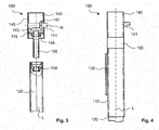
- Fig. 3 illustrates the function of the spindle mechanism and the structure of the actuator 140 for actuating this spindle mechanism.
- the outer support tube 110 is not shown.
- the spindle mechanism includes a spindle nut 150 fixedly or floatingly disposed at the upper axial end in the inner support tube 120, and a spindle 155 (eg, with a trapezoidal motion thread) that engages the spindle nut 150 (the engagement is not shown) and the spindle is attached to the actuator 140 at its upper axial end.
- the inner support tube 120 can be moved along the longitudinal axis L relative to the outer support tube 110.
- the inner support tube 120 is retracted into the outer support tube 110 or extended out of the outer support tube 110.
- the actuating device 140 comprises an input shaft 141 for a hand crank or a drive motor.
- the longitudinal or rotational axis M of Input shaft 141 extends perpendicular to the longitudinal or rotational axis L of the spindle 155.
- a first bevel gear 142 is rotatably mounted, which engages with its toothing in a second bevel gear 143, wherein the second bevel gear 143 rotatably connected to the spindle 155 is.
- the first (driving) bevel gear 142 and the second (driven) bevel gear 143 form a bevel gear, which converts a rotational movement on the input shaft 141 in a rotational movement of the spindle 155 and in a spindle rotation.
- the spindle 155 is inserted from below into the actuator 140 and rotatably connected directly or indirectly with the second bevel gear 143.
- a rolling bearing 144 is provided for axial and / or radial support of the upper axial end of the spindle 155.
- the upper spindle bearing is integrated into the actuator 140.
- Actuator 140 may include an integrated multi-speed variable ratio transmission as discussed above.
- Fig. 4 shows an alternative embodiment of a support device according to the invention with a transmission device 160, which has a switchable multi-speed transmission gear (see the corresponding above explanations).
- the transmission device 160 is also formed as a separate structural unit and aligned between the separately formed actuator 140 and the outer support tube 110 incorporated.
- the transmission device 160 could, for example, also be flanged laterally to the actuating device 140.
Landscapes
- Engineering & Computer Science (AREA)
- Mechanical Engineering (AREA)
- Chemical & Material Sciences (AREA)
- Combustion & Propulsion (AREA)
- Transportation (AREA)
- Vehicle Cleaning, Maintenance, Repair, Refitting, And Outriggers (AREA)
- Jib Cranes (AREA)
Applications Claiming Priority (1)
| Application Number | Priority Date | Filing Date | Title |
|---|---|---|---|
| DE102011081455.8A DE102011081455B4 (de) | 2011-08-24 | 2011-08-24 | Stützvorrichtung für einen Sattelanhänger und Sattelanhänger mit einer Stützvorrichtung sowie Betätigungseinrichtung und Getriebeeinrichtung |
Publications (3)
| Publication Number | Publication Date |
|---|---|
| EP2562058A2 true EP2562058A2 (fr) | 2013-02-27 |
| EP2562058A3 EP2562058A3 (fr) | 2013-08-28 |
| EP2562058B1 EP2562058B1 (fr) | 2015-03-25 |
Family
ID=46614373
Family Applications (1)
| Application Number | Title | Priority Date | Filing Date |
|---|---|---|---|
| EP12179181.8A Active EP2562058B1 (fr) | 2011-08-24 | 2012-08-03 | Dispositif d'appui monté de manière modulaire pour un semi-remorque et semi-remorque doté d'un tel dispositif d'appui |
Country Status (3)
| Country | Link |
|---|---|
| US (1) | US8967667B2 (fr) |
| EP (1) | EP2562058B1 (fr) |
| DE (1) | DE102011081455B4 (fr) |
Families Citing this family (3)
| Publication number | Priority date | Publication date | Assignee | Title |
|---|---|---|---|---|
| US20140246637A1 (en) * | 2013-03-04 | 2014-09-04 | Cequent Consumer Products, Inc. | Dual wind jack |
| US20230303039A1 (en) | 2022-03-28 | 2023-09-28 | Saf-Holland, Inc. | Landing gear assembly |
| US12325387B2 (en) | 2022-03-28 | 2025-06-10 | Saf-Holland, Inc. | Landing gear assembly |
Citations (1)
| Publication number | Priority date | Publication date | Assignee | Title |
|---|---|---|---|---|
| DE202006012472U1 (de) | 2006-08-14 | 2006-12-28 | Riedl, Reinhold, Dipl.-Ing. | Höhenverstellbare Stütze für Sattelauflieger o.dgl. |
Family Cites Families (11)
| Publication number | Priority date | Publication date | Assignee | Title |
|---|---|---|---|---|
| US2232187A (en) * | 1940-05-27 | 1941-02-18 | Fruehauf Trailer Co | Supporting leg structure for semitrailers |
| US3182956A (en) * | 1962-05-17 | 1965-05-11 | Westran Corp | Landing gear structure for semitrailers and the like |
| DE1926161A1 (de) * | 1969-05-22 | 1970-12-10 | Haamann Winden Hebezeug | Abstuetzvorrichtung,insbesondere fuer Sattelauflieger |
| US3861648A (en) * | 1974-01-09 | 1975-01-21 | Pullman Inc | Two-speed trailer landing gear safety arrangement |
| US5199738A (en) * | 1991-04-16 | 1993-04-06 | Jost International Of Grand Haven Michigan | Landing gear for semitrailers |
| US5542647A (en) * | 1995-03-20 | 1996-08-06 | Huetsch; Larry C. | Two-speed jack |
| US5904342A (en) * | 1998-03-17 | 1999-05-18 | Holland Hitch Company | Landing gear crank handle |
| US6623035B1 (en) * | 1999-05-05 | 2003-09-23 | Actuant Corporation | Landing gear |
| US7055859B2 (en) * | 2002-04-02 | 2006-06-06 | The Holland Group, Inc. | Landing gear and method of assembly |
| DE102006012472B3 (de) | 2006-03-16 | 2007-09-27 | Sp-Gmbh & Co. Kg | Bräunungsgerät |
| US8051545B2 (en) * | 2006-04-27 | 2011-11-08 | SAF Holland, Inc. | Landing gear and method of assembly |
-
2011
- 2011-08-24 DE DE102011081455.8A patent/DE102011081455B4/de not_active Expired - Fee Related
-
2012
- 2012-08-03 EP EP12179181.8A patent/EP2562058B1/fr active Active
- 2012-08-21 US US13/590,684 patent/US8967667B2/en active Active
Patent Citations (1)
| Publication number | Priority date | Publication date | Assignee | Title |
|---|---|---|---|---|
| DE202006012472U1 (de) | 2006-08-14 | 2006-12-28 | Riedl, Reinhold, Dipl.-Ing. | Höhenverstellbare Stütze für Sattelauflieger o.dgl. |
Also Published As
| Publication number | Publication date |
|---|---|
| US20130213162A1 (en) | 2013-08-22 |
| EP2562058B1 (fr) | 2015-03-25 |
| US8967667B2 (en) | 2015-03-03 |
| EP2562058A3 (fr) | 2013-08-28 |
| DE102011081455B4 (de) | 2015-06-03 |
| DE102011081455A1 (de) | 2013-02-28 |
Similar Documents
| Publication | Publication Date | Title |
|---|---|---|
| EP3322632B1 (fr) | Actionneur à rétroaction pour un dispositif de direction | |
| EP1457405B1 (fr) | Direction assistée | |
| EP3700799B1 (fr) | Colonne de direction pour véhicule automobile | |
| EP1689632A1 (fr) | Direction a superposition pour un vehicule | |
| DE3027806C2 (de) | Triebachse für Omnibusse | |
| WO2011006774A1 (fr) | Dispositif de motorisation d'un composant automobile, en particulier d'une trappe de carrosserie | |
| WO2008019973A1 (fr) | Support réglable en hauteur destiné à des semi-remorques ou similaires | |
| DE102019217279A1 (de) | Feedback-Aktuator für eine Lenkeinrichtung eines Kraftfahrzeugs | |
| DE2036006C2 (de) | Wechselgetriebe insbesondere für Kraftfahrzeuge | |
| EP3439929B1 (fr) | Actionneur de frein | |
| DE102006038396A1 (de) | Frontachsgetriebe | |
| EP2562058B1 (fr) | Dispositif d'appui monté de manière modulaire pour un semi-remorque et semi-remorque doté d'un tel dispositif d'appui | |
| DE102006029283A1 (de) | Lenkrad für Flurförderfahrzeuge | |
| DE102017130073B3 (de) | Niveauverstellvorrichtung für ein Kraftfahrzeug | |
| DE102017211461B4 (de) | Lenkgetriebe | |
| DE102008021591A1 (de) | Elektromechanische Lenkung | |
| DE102016121412A1 (de) | Festlager und Lenkgetriebe | |
| WO2020048668A1 (fr) | Direction électromécanique de véhicule | |
| DE102006002485A1 (de) | Antriebs- und Lenkeinheit für ein Rad eines Flurförderzeugs | |
| DE102010002569A1 (de) | Lenkgetriebe und damit ausgestattete Servolenkung | |
| DE102011081340B3 (de) | Stützvorrichtung für einen Sattelanhänger, umfassend einen Spindelmechanismus mit mehrteiliger Spindel, sowie Sattelanhänger mit einer solchen Stützvorrichtung und einer Spindel zur Verwendung in einer Stützvorrichtung | |
| DE102018215188A1 (de) | Elektromechanische Fahrzeuglenkung | |
| EP2517946B1 (fr) | Mécanisme de direction à crémaillère pour un véhicule | |
| DE102016212812A1 (de) | Lenkung für ein Kraftfahrzeug, insbesondere für ein Nutzfahrzeug, mit Lenkwelle und Kugelgewindemutter | |
| DE102007010003A1 (de) | Lenkgetriebe |
Legal Events
| Date | Code | Title | Description |
|---|---|---|---|
| PUAI | Public reference made under article 153(3) epc to a published international application that has entered the european phase |
Free format text: ORIGINAL CODE: 0009012 |
|
| AK | Designated contracting states |
Kind code of ref document: A2 Designated state(s): AL AT BE BG CH CY CZ DE DK EE ES FI FR GB GR HR HU IE IS IT LI LT LU LV MC MK MT NL NO PL PT RO RS SE SI SK SM TR |
|
| AX | Request for extension of the european patent |
Extension state: BA ME |
|
| PUAL | Search report despatched |
Free format text: ORIGINAL CODE: 0009013 |
|
| AK | Designated contracting states |
Kind code of ref document: A3 Designated state(s): AL AT BE BG CH CY CZ DE DK EE ES FI FR GB GR HR HU IE IS IT LI LT LU LV MC MK MT NL NO PL PT RO RS SE SI SK SM TR |
|
| AX | Request for extension of the european patent |
Extension state: BA ME |
|
| RIC1 | Information provided on ipc code assigned before grant |
Ipc: B60S 9/08 20060101AFI20130719BHEP |
|
| 17P | Request for examination filed |
Effective date: 20140110 |
|
| RBV | Designated contracting states (corrected) |
Designated state(s): AL AT BE BG CH CY CZ DE DK EE ES FI FR GB GR HR HU IE IS IT LI LT LU LV MC MK MT NL NO PL PT RO RS SE SI SK SM TR |
|
| 17Q | First examination report despatched |
Effective date: 20140318 |
|
| GRAP | Despatch of communication of intention to grant a patent |
Free format text: ORIGINAL CODE: EPIDOSNIGR1 |
|
| INTG | Intention to grant announced |
Effective date: 20141028 |
|
| GRAS | Grant fee paid |
Free format text: ORIGINAL CODE: EPIDOSNIGR3 |
|
| GRAA | (expected) grant |
Free format text: ORIGINAL CODE: 0009210 |
|
| AK | Designated contracting states |
Kind code of ref document: B1 Designated state(s): AL AT BE BG CH CY CZ DE DK EE ES FI FR GB GR HR HU IE IS IT LI LT LU LV MC MK MT NL NO PL PT RO RS SE SI SK SM TR |
|
| REG | Reference to a national code |
Ref country code: GB Ref legal event code: FG4D Free format text: NOT ENGLISH |
|
| REG | Reference to a national code |
Ref country code: CH Ref legal event code: EP |
|
| REG | Reference to a national code |
Ref country code: IE Ref legal event code: FG4D Free format text: LANGUAGE OF EP DOCUMENT: GERMAN |
|
| REG | Reference to a national code |
Ref country code: DE Ref legal event code: R096 Ref document number: 502012002625 Country of ref document: DE Effective date: 20150507 |
|
| REG | Reference to a national code |
Ref country code: AT Ref legal event code: REF Ref document number: 717684 Country of ref document: AT Kind code of ref document: T Effective date: 20150515 |
|
| REG | Reference to a national code |
Ref country code: NL Ref legal event code: T3 |
|
| PG25 | Lapsed in a contracting state [announced via postgrant information from national office to epo] |
Ref country code: HR Free format text: LAPSE BECAUSE OF FAILURE TO SUBMIT A TRANSLATION OF THE DESCRIPTION OR TO PAY THE FEE WITHIN THE PRESCRIBED TIME-LIMIT Effective date: 20150325 Ref country code: SE Free format text: LAPSE BECAUSE OF FAILURE TO SUBMIT A TRANSLATION OF THE DESCRIPTION OR TO PAY THE FEE WITHIN THE PRESCRIBED TIME-LIMIT Effective date: 20150325 Ref country code: FI Free format text: LAPSE BECAUSE OF FAILURE TO SUBMIT A TRANSLATION OF THE DESCRIPTION OR TO PAY THE FEE WITHIN THE PRESCRIBED TIME-LIMIT Effective date: 20150325 Ref country code: LT Free format text: LAPSE BECAUSE OF FAILURE TO SUBMIT A TRANSLATION OF THE DESCRIPTION OR TO PAY THE FEE WITHIN THE PRESCRIBED TIME-LIMIT Effective date: 20150325 |
|
| REG | Reference to a national code |
Ref country code: LT Ref legal event code: MG4D |
|
| PG25 | Lapsed in a contracting state [announced via postgrant information from national office to epo] |
Ref country code: GR Free format text: LAPSE BECAUSE OF FAILURE TO SUBMIT A TRANSLATION OF THE DESCRIPTION OR TO PAY THE FEE WITHIN THE PRESCRIBED TIME-LIMIT Effective date: 20150626 Ref country code: RS Free format text: LAPSE BECAUSE OF FAILURE TO SUBMIT A TRANSLATION OF THE DESCRIPTION OR TO PAY THE FEE WITHIN THE PRESCRIBED TIME-LIMIT Effective date: 20150325 Ref country code: LV Free format text: LAPSE BECAUSE OF FAILURE TO SUBMIT A TRANSLATION OF THE DESCRIPTION OR TO PAY THE FEE WITHIN THE PRESCRIBED TIME-LIMIT Effective date: 20150325 |
|
| PG25 | Lapsed in a contracting state [announced via postgrant information from national office to epo] |
Ref country code: CZ Free format text: LAPSE BECAUSE OF FAILURE TO SUBMIT A TRANSLATION OF THE DESCRIPTION OR TO PAY THE FEE WITHIN THE PRESCRIBED TIME-LIMIT Effective date: 20150325 Ref country code: SK Free format text: LAPSE BECAUSE OF FAILURE TO SUBMIT A TRANSLATION OF THE DESCRIPTION OR TO PAY THE FEE WITHIN THE PRESCRIBED TIME-LIMIT Effective date: 20150325 Ref country code: RO Free format text: LAPSE BECAUSE OF FAILURE TO SUBMIT A TRANSLATION OF THE DESCRIPTION OR TO PAY THE FEE WITHIN THE PRESCRIBED TIME-LIMIT Effective date: 20150325 Ref country code: ES Free format text: LAPSE BECAUSE OF FAILURE TO SUBMIT A TRANSLATION OF THE DESCRIPTION OR TO PAY THE FEE WITHIN THE PRESCRIBED TIME-LIMIT Effective date: 20150325 Ref country code: EE Free format text: LAPSE BECAUSE OF FAILURE TO SUBMIT A TRANSLATION OF THE DESCRIPTION OR TO PAY THE FEE WITHIN THE PRESCRIBED TIME-LIMIT Effective date: 20150325 Ref country code: PT Free format text: LAPSE BECAUSE OF FAILURE TO SUBMIT A TRANSLATION OF THE DESCRIPTION OR TO PAY THE FEE WITHIN THE PRESCRIBED TIME-LIMIT Effective date: 20150727 |
|
| PG25 | Lapsed in a contracting state [announced via postgrant information from national office to epo] |
Ref country code: PL Free format text: LAPSE BECAUSE OF FAILURE TO SUBMIT A TRANSLATION OF THE DESCRIPTION OR TO PAY THE FEE WITHIN THE PRESCRIBED TIME-LIMIT Effective date: 20150325 Ref country code: IS Free format text: LAPSE BECAUSE OF FAILURE TO SUBMIT A TRANSLATION OF THE DESCRIPTION OR TO PAY THE FEE WITHIN THE PRESCRIBED TIME-LIMIT Effective date: 20150725 |
|
| REG | Reference to a national code |
Ref country code: DE Ref legal event code: R097 Ref document number: 502012002625 Country of ref document: DE |
|
| PG25 | Lapsed in a contracting state [announced via postgrant information from national office to epo] |
Ref country code: DK Free format text: LAPSE BECAUSE OF FAILURE TO SUBMIT A TRANSLATION OF THE DESCRIPTION OR TO PAY THE FEE WITHIN THE PRESCRIBED TIME-LIMIT Effective date: 20150325 |
|
| PLBE | No opposition filed within time limit |
Free format text: ORIGINAL CODE: 0009261 |
|
| STAA | Information on the status of an ep patent application or granted ep patent |
Free format text: STATUS: NO OPPOSITION FILED WITHIN TIME LIMIT |
|
| 26N | No opposition filed |
Effective date: 20160105 |
|
| PG25 | Lapsed in a contracting state [announced via postgrant information from national office to epo] |
Ref country code: LU Free format text: LAPSE BECAUSE OF FAILURE TO SUBMIT A TRANSLATION OF THE DESCRIPTION OR TO PAY THE FEE WITHIN THE PRESCRIBED TIME-LIMIT Effective date: 20150803 Ref country code: MC Free format text: LAPSE BECAUSE OF FAILURE TO SUBMIT A TRANSLATION OF THE DESCRIPTION OR TO PAY THE FEE WITHIN THE PRESCRIBED TIME-LIMIT Effective date: 20150325 |
|
| REG | Reference to a national code |
Ref country code: CH Ref legal event code: PL |
|
| PG25 | Lapsed in a contracting state [announced via postgrant information from national office to epo] |
Ref country code: IT Free format text: LAPSE BECAUSE OF FAILURE TO SUBMIT A TRANSLATION OF THE DESCRIPTION OR TO PAY THE FEE WITHIN THE PRESCRIBED TIME-LIMIT Effective date: 20150325 Ref country code: CH Free format text: LAPSE BECAUSE OF NON-PAYMENT OF DUE FEES Effective date: 20150831 Ref country code: LI Free format text: LAPSE BECAUSE OF NON-PAYMENT OF DUE FEES Effective date: 20150831 |
|
| PG25 | Lapsed in a contracting state [announced via postgrant information from national office to epo] |
Ref country code: SI Free format text: LAPSE BECAUSE OF FAILURE TO SUBMIT A TRANSLATION OF THE DESCRIPTION OR TO PAY THE FEE WITHIN THE PRESCRIBED TIME-LIMIT Effective date: 20150325 |
|
| REG | Reference to a national code |
Ref country code: IE Ref legal event code: MM4A |
|
| PG25 | Lapsed in a contracting state [announced via postgrant information from national office to epo] |
Ref country code: IE Free format text: LAPSE BECAUSE OF NON-PAYMENT OF DUE FEES Effective date: 20150803 |
|
| REG | Reference to a national code |
Ref country code: FR Ref legal event code: PLFP Year of fee payment: 5 |
|
| PG25 | Lapsed in a contracting state [announced via postgrant information from national office to epo] |
Ref country code: MT Free format text: LAPSE BECAUSE OF FAILURE TO SUBMIT A TRANSLATION OF THE DESCRIPTION OR TO PAY THE FEE WITHIN THE PRESCRIBED TIME-LIMIT Effective date: 20150325 |
|
| PG25 | Lapsed in a contracting state [announced via postgrant information from national office to epo] |
Ref country code: NO Free format text: LAPSE BECAUSE OF FAILURE TO SUBMIT A TRANSLATION OF THE DESCRIPTION OR TO PAY THE FEE WITHIN THE PRESCRIBED TIME-LIMIT Effective date: 20150625 Ref country code: BG Free format text: LAPSE BECAUSE OF FAILURE TO SUBMIT A TRANSLATION OF THE DESCRIPTION OR TO PAY THE FEE WITHIN THE PRESCRIBED TIME-LIMIT Effective date: 20150325 Ref country code: SM Free format text: LAPSE BECAUSE OF FAILURE TO SUBMIT A TRANSLATION OF THE DESCRIPTION OR TO PAY THE FEE WITHIN THE PRESCRIBED TIME-LIMIT Effective date: 20150325 Ref country code: HU Free format text: LAPSE BECAUSE OF FAILURE TO SUBMIT A TRANSLATION OF THE DESCRIPTION OR TO PAY THE FEE WITHIN THE PRESCRIBED TIME-LIMIT; INVALID AB INITIO Effective date: 20120803 |
|
| PG25 | Lapsed in a contracting state [announced via postgrant information from national office to epo] |
Ref country code: CY Free format text: LAPSE BECAUSE OF FAILURE TO SUBMIT A TRANSLATION OF THE DESCRIPTION OR TO PAY THE FEE WITHIN THE PRESCRIBED TIME-LIMIT Effective date: 20150325 |
|
| PG25 | Lapsed in a contracting state [announced via postgrant information from national office to epo] |
Ref country code: BE Free format text: LAPSE BECAUSE OF NON-PAYMENT OF DUE FEES Effective date: 20150831 |
|
| REG | Reference to a national code |
Ref country code: FR Ref legal event code: PLFP Year of fee payment: 6 |
|
| PG25 | Lapsed in a contracting state [announced via postgrant information from national office to epo] |
Ref country code: MK Free format text: LAPSE BECAUSE OF FAILURE TO SUBMIT A TRANSLATION OF THE DESCRIPTION OR TO PAY THE FEE WITHIN THE PRESCRIBED TIME-LIMIT Effective date: 20150325 |
|
| REG | Reference to a national code |
Ref country code: FR Ref legal event code: PLFP Year of fee payment: 7 |
|
| REG | Reference to a national code |
Ref country code: AT Ref legal event code: MM01 Ref document number: 717684 Country of ref document: AT Kind code of ref document: T Effective date: 20170803 |
|
| PG25 | Lapsed in a contracting state [announced via postgrant information from national office to epo] |
Ref country code: AL Free format text: LAPSE BECAUSE OF FAILURE TO SUBMIT A TRANSLATION OF THE DESCRIPTION OR TO PAY THE FEE WITHIN THE PRESCRIBED TIME-LIMIT Effective date: 20150325 |
|
| PG25 | Lapsed in a contracting state [announced via postgrant information from national office to epo] |
Ref country code: AT Free format text: LAPSE BECAUSE OF NON-PAYMENT OF DUE FEES Effective date: 20170803 |
|
| PGFP | Annual fee paid to national office [announced via postgrant information from national office to epo] |
Ref country code: NL Payment date: 20190821 Year of fee payment: 8 |
|
| REG | Reference to a national code |
Ref country code: NL Ref legal event code: MM Effective date: 20200901 |
|
| PG25 | Lapsed in a contracting state [announced via postgrant information from national office to epo] |
Ref country code: NL Free format text: LAPSE BECAUSE OF NON-PAYMENT OF DUE FEES Effective date: 20200901 |
|
| PGFP | Annual fee paid to national office [announced via postgrant information from national office to epo] |
Ref country code: GB Payment date: 20210824 Year of fee payment: 10 |
|
| PGFP | Annual fee paid to national office [announced via postgrant information from national office to epo] |
Ref country code: FR Payment date: 20220822 Year of fee payment: 11 |
|
| GBPC | Gb: european patent ceased through non-payment of renewal fee |
Effective date: 20220803 |
|
| P01 | Opt-out of the competence of the unified patent court (upc) registered |
Effective date: 20230509 |
|
| PG25 | Lapsed in a contracting state [announced via postgrant information from national office to epo] |
Ref country code: GB Free format text: LAPSE BECAUSE OF NON-PAYMENT OF DUE FEES Effective date: 20220803 |
|
| PG25 | Lapsed in a contracting state [announced via postgrant information from national office to epo] |
Ref country code: FR Free format text: LAPSE BECAUSE OF NON-PAYMENT OF DUE FEES Effective date: 20230831 |
|
| PGFP | Annual fee paid to national office [announced via postgrant information from national office to epo] |
Ref country code: DE Payment date: 20250514 Year of fee payment: 14 |
|
| PGFP | Annual fee paid to national office [announced via postgrant information from national office to epo] |
Ref country code: TR Payment date: 20250729 Year of fee payment: 14 |