EP2562360A2 - Keramische Matrix-Verbundstoff-Schaufelstruktur mit Umwicklung für einen Gasturbinenmotor - Google Patents
Keramische Matrix-Verbundstoff-Schaufelstruktur mit Umwicklung für einen Gasturbinenmotor Download PDFInfo
- Publication number
- EP2562360A2 EP2562360A2 EP20120181418 EP12181418A EP2562360A2 EP 2562360 A2 EP2562360 A2 EP 2562360A2 EP 20120181418 EP20120181418 EP 20120181418 EP 12181418 A EP12181418 A EP 12181418A EP 2562360 A2 EP2562360 A2 EP 2562360A2
- Authority
- EP
- European Patent Office
- Prior art keywords
- vane structure
- ring
- platform segment
- recited
- cmc
- Prior art date
- Legal status (The legal status is an assumption and is not a legal conclusion. Google has not performed a legal analysis and makes no representation as to the accuracy of the status listed.)
- Granted
Links
Images


Classifications
-
- F—MECHANICAL ENGINEERING; LIGHTING; HEATING; WEAPONS; BLASTING
- F01—MACHINES OR ENGINES IN GENERAL; ENGINE PLANTS IN GENERAL; STEAM ENGINES
- F01D—NON-POSITIVE DISPLACEMENT MACHINES OR ENGINES, e.g. STEAM TURBINES
- F01D5/00—Blades; Blade-carrying members; Heating, heat-insulating, cooling or antivibration means on the blades or the members
- F01D5/12—Blades
- F01D5/14—Form or construction
- F01D5/147—Construction, i.e. structural features, e.g. of weight-saving hollow blades
-
- C—CHEMISTRY; METALLURGY
- C04—CEMENTS; CONCRETE; ARTIFICIAL STONE; CERAMICS; REFRACTORIES
- C04B—LIME, MAGNESIA; SLAG; CEMENTS; COMPOSITIONS THEREOF, e.g. MORTARS, CONCRETE OR LIKE BUILDING MATERIALS; ARTIFICIAL STONE; CERAMICS; REFRACTORIES; TREATMENT OF NATURAL STONE
- C04B35/00—Shaped ceramic products characterised by their composition; Ceramics compositions; Processing powders of inorganic compounds preparatory to the manufacturing of ceramic products
- C04B35/71—Ceramic products containing macroscopic reinforcing agents
- C04B35/78—Ceramic products containing macroscopic reinforcing agents containing non-metallic materials
- C04B35/80—Fibres, filaments, whiskers, platelets, or the like
-
- F—MECHANICAL ENGINEERING; LIGHTING; HEATING; WEAPONS; BLASTING
- F01—MACHINES OR ENGINES IN GENERAL; ENGINE PLANTS IN GENERAL; STEAM ENGINES
- F01D—NON-POSITIVE DISPLACEMENT MACHINES OR ENGINES, e.g. STEAM TURBINES
- F01D9/00—Stators
- F01D9/02—Nozzles; Nozzle boxes; Stator blades; Guide conduits, e.g. individual nozzles
- F01D9/04—Nozzles; Nozzle boxes; Stator blades; Guide conduits, e.g. individual nozzles forming ring or sector
- F01D9/041—Nozzles; Nozzle boxes; Stator blades; Guide conduits, e.g. individual nozzles forming ring or sector using blades
-
- F—MECHANICAL ENGINEERING; LIGHTING; HEATING; WEAPONS; BLASTING
- F01—MACHINES OR ENGINES IN GENERAL; ENGINE PLANTS IN GENERAL; STEAM ENGINES
- F01D—NON-POSITIVE DISPLACEMENT MACHINES OR ENGINES, e.g. STEAM TURBINES
- F01D5/00—Blades; Blade-carrying members; Heating, heat-insulating, cooling or antivibration means on the blades or the members
- F01D5/12—Blades
- F01D5/28—Selecting particular materials; Particular measures relating thereto; Measures against erosion or corrosion
- F01D5/284—Selection of ceramic materials
-
- F—MECHANICAL ENGINEERING; LIGHTING; HEATING; WEAPONS; BLASTING
- F05—INDEXING SCHEMES RELATING TO ENGINES OR PUMPS IN VARIOUS SUBCLASSES OF CLASSES F01-F04
- F05D—INDEXING SCHEME FOR ASPECTS RELATING TO NON-POSITIVE-DISPLACEMENT MACHINES OR ENGINES, GAS-TURBINES OR JET-PROPULSION PLANTS
- F05D2240/00—Components
- F05D2240/10—Stators
- F05D2240/12—Fluid guiding means, e.g. vanes
-
- F—MECHANICAL ENGINEERING; LIGHTING; HEATING; WEAPONS; BLASTING
- F05—INDEXING SCHEMES RELATING TO ENGINES OR PUMPS IN VARIOUS SUBCLASSES OF CLASSES F01-F04
- F05D—INDEXING SCHEME FOR ASPECTS RELATING TO NON-POSITIVE-DISPLACEMENT MACHINES OR ENGINES, GAS-TURBINES OR JET-PROPULSION PLANTS
- F05D2250/00—Geometry
- F05D2250/70—Shape
- F05D2250/75—Shape given by its similarity to a letter, e.g. T-shaped
-
- F—MECHANICAL ENGINEERING; LIGHTING; HEATING; WEAPONS; BLASTING
- F05—INDEXING SCHEMES RELATING TO ENGINES OR PUMPS IN VARIOUS SUBCLASSES OF CLASSES F01-F04
- F05D—INDEXING SCHEME FOR ASPECTS RELATING TO NON-POSITIVE-DISPLACEMENT MACHINES OR ENGINES, GAS-TURBINES OR JET-PROPULSION PLANTS
- F05D2300/00—Materials; Properties thereof
- F05D2300/60—Properties or characteristics given to material by treatment or manufacturing
- F05D2300/603—Composites; e.g. fibre-reinforced
- F05D2300/6033—Ceramic matrix composites [CMC]
-
- F—MECHANICAL ENGINEERING; LIGHTING; HEATING; WEAPONS; BLASTING
- F05—INDEXING SCHEMES RELATING TO ENGINES OR PUMPS IN VARIOUS SUBCLASSES OF CLASSES F01-F04
- F05D—INDEXING SCHEME FOR ASPECTS RELATING TO NON-POSITIVE-DISPLACEMENT MACHINES OR ENGINES, GAS-TURBINES OR JET-PROPULSION PLANTS
- F05D2300/00—Materials; Properties thereof
- F05D2300/60—Properties or characteristics given to material by treatment or manufacturing
- F05D2300/603—Composites; e.g. fibre-reinforced
- F05D2300/6034—Orientation of fibres, weaving, ply angle
Definitions
- the present disclosure relates to a gas turbine engine, and more particularly to Ceramic Matrix Composite (CMC) components therefor.
- CMC Ceramic Matrix Composite
- the turbine section of a gas turbine engine includes a multiple of airfoils which operate at elevated temperatures in a strenuous, oxidizing type of gas flow environment and are typically manufactured of high temperature superalloys.
- CMC materials provide higher temperature capability than metal alloys and a high strength to weight ratio. CMC materials, however, may require particular manufacturing approaches as the fiber orientation primarily determines the strength capability.
- a vane structure for a gas turbine engine includes an airfoil section with a platform segment adjacent to a ring.
- An insert is adjacent to the platform segment.
- An overwrap is wound around the ring and the insert.
- a vane structure for a gas turbine engine includes an insert adjacent to first and second T-shaped platform segments.
- An overwrap is wound around a ring and the first and second T-shaped platform segments.
- the ring may be manufactured of a ceramic matrix composite (CMC) material.
- the first and second T-shaped platform segments may each include a multiple of ceramic matrix composite (CMC) plies that bend apart to define a generally perpendicular orientation which form fillets.
- a filler for example a preformed monolithic ceramic member, may be within said first T-shaped platform segment and said second T-shaped platform segment.
- the preformed monolithic ceramic member my be generally triangular in cross-section.
- the overwrap may include a tow.
- the insert may be a preformed monolithic ceramic member and may be airfoil shaped.
- a method of assembling a vane structure for a gas turbine engine includes: positioning an airfoil section with a platform segment adjacent to a ring; positioning an insert at least partially over the platform segment; and winding an overwrap around the ring and the insert.
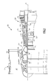
- FIG. 1 schematically illustrates a gas turbine engine 20.
- the gas turbine engine 20 is disclosed herein as a two-spool turbofan that generally incorporates a fan section 22, a compressor section 24, a combustor section 26 and a turbine section 28.
- Alternative engines might include an augmentor section (not shown) among other systems or features.
- the fan section 22 drives air along a bypass flowpath while the compressor section 24 drives air along a core flowpath for compression and communication into the combustor section 26 then expansion through the turbine section 28.
- FIG. 1 schematically illustrates a gas turbine engine 20.
- the gas turbine engine 20 is disclosed herein as a two-spool turbofan that generally incorporates a fan section 22, a compressor section 24, a combustor section 26 and a turbine section 28.
- Alternative engines might include an augmentor section (not shown) among other systems or features.
- the fan section 22 drives air along a bypass flowpath while the compressor section 24 drives air along a core flowpath for compression and communication into the combustor section 26
- the engine 20 generally includes a low speed spool 30 and a high speed spool 32 mounted for rotation about an engine central longitudinal axis A relative to an engine static structure 36 via several bearing systems 38. It should be understood that various bearing systems 38 at various locations may alternatively or additionally be provided.
- the low speed spool 30 generally includes an inner shaft 40 that interconnects a fan 42, a low pressure compressor 44 and a low pressure turbine 46.
- the inner shaft 40 is connected to the fan 42 through a geared architecture 48 to drive the fan 42 at a lower speed than the low speed spool 30.
- the high speed spool 32 includes an outer shaft 50 that interconnects a high pressure compressor 52 and high pressure turbine 54.
- a combustor 56 is arranged between the high pressure compressor 52 and the high pressure turbine 54.
- the inner shaft 40 and the outer shaft 50 are concentric and rotate about the engine central longitudinal axis A which is collinear with their longitudinal axes.
- the core airflow is compressed by the low pressure compressor 44 then the high pressure compressor 52, mixed and burned with fuel in the combustor 56, then expanded over the high pressure turbine 54 and low pressure turbine 46.
- the turbines 54, 56 rotationally drive the respective low speed spool 30 and high speed spool 32 in response to the expansion.
- the low pressure turbine 46 generally includes a low pressure turbine case 60 with a multiple of low pressure turbine stages.
- the stages include a multiple of rotor structures 62A, 62B, 62C interspersed with vane structures 64A, 64B.
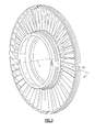
- Each of the rotor structures 62A, 62B, 62C and each of the vane structure 64A, 64B may include airfoils 66 manufactured of a ceramic matrix composite (CMC) material typically in a ring-strut ring full hoop structure ( Figures 3 and 4 ).
- CMC material for componentry discussed herein may include, but are not limited to, for example, S200 and SiC/SiC.
- low pressure turbine Although depicted as a low pressure turbine in the disclosed embodiment, it should also be understood that the concepts described herein are not limited to use with low pressure turbines as the teachings may be applied to other sections such as high pressure turbines, high pressure compressors, low pressure compressors, as well as intermediate pressure turbines and intermediate pressure compressors of a three-spool architecture gas turbine engine.
- FIG. 5 one CMC airfoil 66 "singlet" usable with a ring-strut-ring full hoop structure is illustrated. Although a somewhat generic airfoil 66 will be described in detail hereafter, it should be understood that various rotary airfoils or blades and static airfoils or vanes may be particularly amenable to the fabrication described herein.
- the CMC airfoil 66 generally includes an airfoil portion 68 defined between a leading edge 70 and a trailing edge 72. It should be understood that an airfoil portion 68 with twists of between, for example, 90 - 120 degrees may be readily included.
- Each airfoil 66 includes a fillet section 74, 76 to provide a transition T-section between the airfoil portion 68 and a platform segment 78, 80.
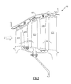
- the platform segments 78, 80 are adjacent an inner diameter and an outer diameter of the core gas path C ( Figure 2 ).
- the airfoil portion 68 includes a generally concave shaped portion which forms a pressure side 82 and a generally convex shaped portion which forms a suction side 84.
- the pressure side 82 and the suction side 84 may be formed from a respective first and second multiple of CMC plies 86, 88 which may be bonded together along a central airfoil axis B within a first airfoil portion 86A, 88A which is at least partially parallel to the airfoil axis B of the airfoil portion 68.
- the airfoil portion 68 may be fabricated such that the CMC structural fibers of the respective first and second multiple of CMC plies 86, 88 are arranged to define a radius outward from the airfoil axis B.
- the pressure side 82 and the suction side 84 along with the inner and outer core gas path forming platform segments 78, 80 may be formed with a generally "C" shaped CMC ply orientation by the respective first and second multiple of CMC plies 86, 88.
- the multiple of CMC plies 86, 88 bend apart to define a generally perpendicular orientation to form the radiused fillet sections 74, 76. That is, the multiple of CMC plies 86, 88 bend apart at a second airfoil portion 86B, 88B which is at least partially transverse to the airfoil axis B to form the fillet sections 74, 76.
- the fillet sections 74, 76 blend the airfoil portion 68 into the platform segments 78, 80.
- the outer cap surfaces 90, 92 of the platform segments 78, 80 are then capped by, for example, a third and fourth multiple of CMC plies 94, 96 which are generally transverse to the airfoil axis B to form the T-section.
- the platform segments 78, 80 may include unidirectional plys which are aligned tows with or without weave, as well as additional or alternative fabric plies to obtain a thicker platform segment if so required.
- Triangular areas 98, 100 at which the multiple of CMC uni-tape plies 86, 88 bend apart to form the fillet sections 74, 76 are filled with a filler 102 such as a CMC fabric filler material often referred to as a "noodle" of, for example, a chopped fiber and a tackifier.
- the CMC fabric filler material may additionally be utilized in other areas where pockets or lack of material exist relative to the forming of a feature. These areas may have debited properties but are typically located in areas where they may exist without compromising structural integrity.
- the filler 102 may alternatively be a rigid component 104. It should be understood that examples of such a filler may include monolithic ceramic material such as a silicon carbide, silicon nitride or a metal alloy material.
- the rigid component 104 may be generally triangular in cross-section shaped to fill the triangular areas 98, 100. That is, the filler 102 may be preformed to facilitate assembly into the pockets.
- either or both of the platform segments 78, 80 may be of a circumferential complementary geometry such as a chevron-shape ( Figure 8 ) to provide a complementary abutting edge engagement of each adjacent platform segment to define the inner and outer core gas path. That is, the CMC airfoils 66 are assembled in an adjacent complementary manner to form a ring of airfoils within a CMC outer ring 106 and a CMC inner ring 108 with the respectively adjacent platform segments 78, 80 to form full hoops ( Figure 9 ).
- a circumferential complementary geometry such as a chevron-shape ( Figure 8 ) to provide a complementary abutting edge engagement of each adjacent platform segment to define the inner and outer core gas path. That is, the CMC airfoils 66 are assembled in an adjacent complementary manner to form a ring of airfoils within a CMC outer ring 106 and a CMC inner ring 108 with the respectively adjacent platform segments 78, 80 to form full hoops ( Figure 9
- the CMC outer ring 106 and the CMC inner ring 108 utilize the CMC hoop strength characteristics to form a full hoop shroud in a ring-strut-ring structure. It should be understood that the term full hoop is defined herein as an uninterrupted member such that the airfoils need not pass through apertures formed therethrough.
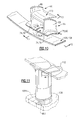
- the platform segments 78, 80 are adj acent to the respective CMC outer ring 106 and the CMC inner ring 108 in the illustrated exploded view. It should be understood that although only a single assembly associated with the platform segment 78 and the respective CMC outer ring 106 is described and illustrated in detail hereafter, the platform segment 80 and the respective CMC inner ring 108 may additionally be assembled in a similar manner. That is, both may be assembled in an equivalent manner or one may be so assembled with the other manufactured in, for example, a tab 80T and slot 108S ( Figure 11 ) architecture.
- the platform segments 78 of a respective multiple of airfoils 66 are arranged in a circumferentially abutted engagement within the respective CMC outer ring 106.
- An insert 110 is located between each pair of airfoil portions 68 over the adjacent platform segments 78.
- the insert 110 may be manufactured of CMC material, monolithic ceramic or metal alloy. That is, the insert 110 is a hard airfoil shaped component which defines a flow surface for the core flow.
- the insert 110 facilitates shaping of the fillet sections 74, 76 as well as provides a smooth surface to receive overwrap 112 ( Figure 12 ).
- the overwrap 112 may be formed of a tow which is a collection of fibers such as a silicon based fiber, a uni-tape, or cloth that is wrapped around the insert 110 and the CMC outer ring 106 to sandwich the platform segments 78 therebetween to provide a self supporting structure ( Figure 13 ).
- the overwrap 112 is wound in a continuous spiral over the vane fillet section 74 to thereby reinforce the T-section of the airfoil 66, and bias the plys in the T-section toward the CMC outer ring 106.
- the overwrap 112 thereby clamps the T-section toward the CMC outer ring 106 to reduce the potential for delamination and minimize the stress riser associated with the displaced layers as plys in compression, or otherwise constrained, are less likely to delaminate at a given load.
- This net increase in capability permits each of the vane singlets to carry cantilevered loads.
- the disclosed fabrication approach allows for ease of production for a singlet or multiple airfoil cluster with a relatively more durable structure.
Landscapes
- Engineering & Computer Science (AREA)
- Mechanical Engineering (AREA)
- General Engineering & Computer Science (AREA)
- Chemical & Material Sciences (AREA)
- Architecture (AREA)
- Ceramic Engineering (AREA)
- Chemical Kinetics & Catalysis (AREA)
- Manufacturing & Machinery (AREA)
- Materials Engineering (AREA)
- Structural Engineering (AREA)
- Organic Chemistry (AREA)
- Turbine Rotor Nozzle Sealing (AREA)
Applications Claiming Priority (1)
| Application Number | Priority Date | Filing Date | Title |
|---|---|---|---|
| US13/215,292 US9103214B2 (en) | 2011-08-23 | 2011-08-23 | Ceramic matrix composite vane structure with overwrap for a gas turbine engine |
Publications (3)
| Publication Number | Publication Date |
|---|---|
| EP2562360A2 true EP2562360A2 (de) | 2013-02-27 |
| EP2562360A3 EP2562360A3 (de) | 2017-03-29 |
| EP2562360B1 EP2562360B1 (de) | 2019-10-02 |
Family
ID=46750224
Family Applications (1)
| Application Number | Title | Priority Date | Filing Date |
|---|---|---|---|
| EP12181418.0A Active EP2562360B1 (de) | 2011-08-23 | 2012-08-22 | Keramische Matrix-Verbundstoff-Schaufelstruktur mit Umwicklung für einen Gasturbinenmotor |
Country Status (2)
| Country | Link |
|---|---|
| US (1) | US9103214B2 (de) |
| EP (1) | EP2562360B1 (de) |
Cited By (8)
| Publication number | Priority date | Publication date | Assignee | Title |
|---|---|---|---|---|
| WO2014143339A1 (en) * | 2013-03-15 | 2014-09-18 | Thomas David J | Gas turbine engine airflow member, corresponding turbomachine component and manufacturing method |
| EP3309366A1 (de) * | 2016-10-14 | 2018-04-18 | Rolls-Royce Corporation | Turbinenmantelanordnung |
| EP3450695A1 (de) * | 2017-08-30 | 2019-03-06 | United Technologies Corporation | Verbundstator mit integrierten plattformen für gasturbinenmotoren |
| EP3587736A1 (de) * | 2018-06-22 | 2020-01-01 | United Technologies Corporation | Zusammengesetztes schaufelblatt mit luftriss in plattform |
| EP3650653A1 (de) * | 2018-11-08 | 2020-05-13 | United Technologies Corporation | Fortsetzung eines schubrohres durch eine leitschaufelplattform zur strukturellen abstützung |
| FR3116863A1 (fr) * | 2020-12-02 | 2022-06-03 | Safran | Procede de fabrication d’une aube composite de turbomachine d’aeronef |
| EP4234887A1 (de) * | 2022-02-28 | 2023-08-30 | Raytheon Technologies Corporation | Gegabelte stoffarchitektur für tragflächen, verfahren zur herstellung davon und tragflächen damit |
| US12467385B1 (en) | 2025-01-09 | 2025-11-11 | General Electric Company | Outlet guide vane mount |
Families Citing this family (30)
| Publication number | Priority date | Publication date | Assignee | Title |
|---|---|---|---|---|
| US9725833B2 (en) * | 2012-07-12 | 2017-08-08 | United Technologies Corporation | Woven structure and method for weaving same |
| EP3062961B1 (de) * | 2013-10-28 | 2020-11-25 | United Technologies Corporation | Vorrichtung zum polieren von schaufeln |
| US10294807B2 (en) * | 2016-05-19 | 2019-05-21 | Honeywell International Inc. | Inter-turbine ducts |
| US10436036B2 (en) * | 2016-07-05 | 2019-10-08 | Safran Aircraft Engines | Fitted platform for a turbine engine fan, and a method of fabricating it |
| US10443625B2 (en) | 2016-09-21 | 2019-10-15 | General Electric Company | Airfoil singlets |
| US10927710B2 (en) | 2018-09-26 | 2021-02-23 | Raytheon Technologies Corporation | Blade outer air seal laminate T-joint |
| US10859268B2 (en) * | 2018-10-03 | 2020-12-08 | Rolls-Royce Plc | Ceramic matrix composite turbine vanes and vane ring assemblies |
| JP7162514B2 (ja) * | 2018-12-07 | 2022-10-28 | 三菱重工業株式会社 | 軸流式ターボ機械及びその翼 |
| US11719440B2 (en) * | 2018-12-19 | 2023-08-08 | Doosan Enerbility Co., Ltd. | Pre-swirler having dimples |
| US10711621B1 (en) * | 2019-02-01 | 2020-07-14 | Rolls-Royce Plc | Turbine vane assembly with ceramic matrix composite components and temperature management features |
| US11162377B2 (en) * | 2019-05-31 | 2021-11-02 | Rolls-Royce High Temperature Composites Inc. | Ceramic matrix composite turbine vane and method for making |
| US11466577B2 (en) * | 2019-10-04 | 2022-10-11 | Raytheon Technologies Corporation | CMC vane mate face flange |
| US11919821B2 (en) | 2019-10-18 | 2024-03-05 | Rtx Corporation | Fiber reinforced composite and method of making |
| US11092022B2 (en) * | 2019-11-04 | 2021-08-17 | Raytheon Technologies Corporation | Vane with chevron face |
| US11268393B2 (en) * | 2019-11-20 | 2022-03-08 | Raytheon Technologies Corporation | Vane retention feature |
| US11352894B2 (en) * | 2019-11-21 | 2022-06-07 | Raytheon Technologies Corporation | Vane with collar |
| US11549380B2 (en) * | 2019-11-21 | 2023-01-10 | Raytheon Technologies Corporation | Contour weaving to form airfoil |
| US11162372B2 (en) | 2019-12-04 | 2021-11-02 | Rolls-Royce Plc | Turbine vane doublet with ceramic matrix composite material construction |
| US11492733B2 (en) * | 2020-02-21 | 2022-11-08 | Raytheon Technologies Corporation | Weave control grid |
| FR3109184B1 (fr) | 2020-04-14 | 2022-04-01 | Safran | Aube en matériau composite comportant des renforts métalliques, et procédé de fabrication d’une telle aube |
| US11504930B2 (en) * | 2021-02-03 | 2022-11-22 | General Electric Company | Compaction system and methods for compacting composite components |
| US12071864B2 (en) * | 2022-01-21 | 2024-08-27 | Rtx Corporation | Turbine section with ceramic support rings and ceramic vane arc segments |
| US12523157B2 (en) * | 2022-05-13 | 2026-01-13 | Rtx Corporation | Ceramic vane ring-strut-ring attachment configuration |
| US11732589B1 (en) | 2022-07-15 | 2023-08-22 | Raytheon Technologies Corporation | Airfoil vane multiplet with interleaved fiber plies |
| US12078083B2 (en) * | 2022-12-20 | 2024-09-03 | Rtx Corporation | Contour weaves for interwoven vanes |
| US12188376B2 (en) * | 2023-03-29 | 2025-01-07 | Pratt & Whitney Canada Corp. | Composite guide vane with insert |
| US20240376017A1 (en) * | 2023-05-12 | 2024-11-14 | Raytheon Technologies Corporation | Prefabricated noodle |
| US12601268B2 (en) * | 2023-08-25 | 2026-04-14 | Rtx Corporation | CMC vane with detuned platform |
| US12326100B1 (en) * | 2024-01-31 | 2025-06-10 | Rtx Corporation | Gas turbine engine component fillets formed of CMC plies |
| US12428965B2 (en) * | 2024-01-31 | 2025-09-30 | Rtx Corporation | Load bearing feature for ceramic matrix composite turbine components |
Family Cites Families (17)
| Publication number | Priority date | Publication date | Assignee | Title |
|---|---|---|---|---|
| US3403844A (en) * | 1967-10-02 | 1968-10-01 | Gen Electric | Bladed member and method for making |
| GB2161110B (en) * | 1984-07-07 | 1988-03-23 | Rolls Royce | An annular bladed member having an integral shroud and a method of manufacture thereof |
| US5522705A (en) * | 1994-05-13 | 1996-06-04 | United Technologies Corporation | Friction damper for gas turbine engine blades |
| US5688426A (en) | 1995-06-07 | 1997-11-18 | The Boeing Company | Hybrid metal webbed composite beam |
| JP4060981B2 (ja) * | 1998-04-08 | 2008-03-12 | 本田技研工業株式会社 | ガスタービンの静翼構造体及びそのユニット |
| FR2817192B1 (fr) * | 2000-11-28 | 2003-08-08 | Snecma Moteurs | Ensemble forme par au moins une pale et une plate-forme de fixation de la pale, pour une turbomachine, et procede pour sa fabrication |
| FR2857660B1 (fr) | 2003-07-18 | 2006-03-03 | Snecma Propulsion Solide | Structure composite thermostructurale a gradient de composition et son procede de fabrication |
| GB0427083D0 (en) * | 2004-12-10 | 2005-01-12 | Rolls Royce Plc | Platform mounted components |
| US7329101B2 (en) | 2004-12-29 | 2008-02-12 | General Electric Company | Ceramic composite with integrated compliance/wear layer |
| US7452182B2 (en) * | 2005-04-07 | 2008-11-18 | Siemens Energy, Inc. | Multi-piece turbine vane assembly |
| GB2427658B (en) * | 2005-06-30 | 2007-08-22 | Rolls Royce Plc | Organic matrix composite integrally bladed rotor |
| US7648336B2 (en) | 2006-01-03 | 2010-01-19 | General Electric Company | Apparatus and method for assembling a gas turbine stator |
| US7371043B2 (en) * | 2006-01-12 | 2008-05-13 | Siemens Power Generation, Inc. | CMC turbine shroud ring segment and fabrication method |
| US7686577B2 (en) | 2006-11-02 | 2010-03-30 | Siemens Energy, Inc. | Stacked laminate fiber wrapped segment |
| GB2447271B (en) * | 2007-03-06 | 2010-02-17 | Rolls Royce Plc | A composite structure |
| GB0901189D0 (en) * | 2009-01-26 | 2009-03-11 | Rolls Royce Plc | Manufacturing a composite component |
| US20110206522A1 (en) * | 2010-02-24 | 2011-08-25 | Ioannis Alvanos | Rotating airfoil fabrication utilizing cmc |
-
2011
- 2011-08-23 US US13/215,292 patent/US9103214B2/en active Active
-
2012
- 2012-08-22 EP EP12181418.0A patent/EP2562360B1/de active Active
Non-Patent Citations (1)
| Title |
|---|
| None |
Cited By (12)
| Publication number | Priority date | Publication date | Assignee | Title |
|---|---|---|---|---|
| WO2014143339A1 (en) * | 2013-03-15 | 2014-09-18 | Thomas David J | Gas turbine engine airflow member, corresponding turbomachine component and manufacturing method |
| US9845688B2 (en) | 2013-03-15 | 2017-12-19 | Rolls-Royce Corporation | Composite blade with an integral blade tip shroud and method of forming the same |
| EP3309366A1 (de) * | 2016-10-14 | 2018-04-18 | Rolls-Royce Corporation | Turbinenmantelanordnung |
| US10697314B2 (en) | 2016-10-14 | 2020-06-30 | Rolls-Royce Corporation | Turbine shroud with I-beam construction |
| EP3450695A1 (de) * | 2017-08-30 | 2019-03-06 | United Technologies Corporation | Verbundstator mit integrierten plattformen für gasturbinenmotoren |
| EP3587736A1 (de) * | 2018-06-22 | 2020-01-01 | United Technologies Corporation | Zusammengesetztes schaufelblatt mit luftriss in plattform |
| EP3650653A1 (de) * | 2018-11-08 | 2020-05-13 | United Technologies Corporation | Fortsetzung eines schubrohres durch eine leitschaufelplattform zur strukturellen abstützung |
| US10724387B2 (en) | 2018-11-08 | 2020-07-28 | Raytheon Technologies Corporation | Continuation of a shear tube through a vane platform for structural support |
| FR3116863A1 (fr) * | 2020-12-02 | 2022-06-03 | Safran | Procede de fabrication d’une aube composite de turbomachine d’aeronef |
| EP4234887A1 (de) * | 2022-02-28 | 2023-08-30 | Raytheon Technologies Corporation | Gegabelte stoffarchitektur für tragflächen, verfahren zur herstellung davon und tragflächen damit |
| US11781435B2 (en) | 2022-02-28 | 2023-10-10 | Rtx Corporation | Bifurcated fabric architecture for airfoils, methods of manufacture thereof and airfoils comprising the same |
| US12467385B1 (en) | 2025-01-09 | 2025-11-11 | General Electric Company | Outlet guide vane mount |
Also Published As
| Publication number | Publication date |
|---|---|
| EP2562360B1 (de) | 2019-10-02 |
| EP2562360A3 (de) | 2017-03-29 |
| US20130052030A1 (en) | 2013-02-28 |
| US9103214B2 (en) | 2015-08-11 |
Similar Documents
| Publication | Publication Date | Title |
|---|---|---|
| US9103214B2 (en) | Ceramic matrix composite vane structure with overwrap for a gas turbine engine | |
| EP2570593B1 (de) | Schaufelsegment aus keramischem Faserverbundwerkstoff für ein Gasturbinentriebwerk, zugehörige Struktur und Montageverfahren | |
| EP2599959B1 (de) | Keramikmatrix-Verbundstrukturen einer Schaufel mit Verstärkungs- Hinterkante für Gasturbinenmotor | |
| EP2570611B1 (de) | Schaufelprofil aus keramischem Faserverbundwerkstoff für ein Gasturbinentriebwerk und zugehöriges Formungsverfahren | |
| EP2570604B1 (de) | Statorbeschaufelung aus keramischem Faserverbundwerkstoff für ein Gasturbinentriebwerk und zugehöriges Formungsverfahren | |
| US8770931B2 (en) | Hybrid Ceramic Matrix Composite vane structures for a gas turbine engine | |
| US8905711B2 (en) | Ceramic matrix composite vane structures for a gas turbine engine turbine | |
| EP2986822B1 (de) | Rotoren mit schaufeln mit dejustiertem elastizitätsmodul | |
| EP2570608B1 (de) | Rotorbaugruppe aus keramischem Faserverbundwerkstoff für ein Gasturbinentriebwerk, zugehörige Turbinenanordnung und Montageverfahren | |
| US20110206522A1 (en) | Rotating airfoil fabrication utilizing cmc | |
| US11220924B2 (en) | Double box composite seal assembly with insert for gas turbine engine | |
| CN110439625B (zh) | 用于叉指转子的复合翼型组件 | |
| US11692444B2 (en) | Gas turbine engine rotor blade having a root section with composite and metallic portions | |
| EP3835553B1 (de) | Nichtmetallische seitenplattendichtungsanordnung für einen gasturbinenmotor | |
| US20210095574A1 (en) | Double box composite seal assembly with fiber density arrangement for gas turbine engine | |
| EP2570605B1 (de) | Rotorscheibe aus keramischem Faserverbundwerkstoff für ein Gasturbinentriebwerk und zugehörige Rotorbaugruppe |
Legal Events
| Date | Code | Title | Description |
|---|---|---|---|
| PUAI | Public reference made under article 153(3) epc to a published international application that has entered the european phase |
Free format text: ORIGINAL CODE: 0009012 |
|
| AK | Designated contracting states |
Kind code of ref document: A2 Designated state(s): AL AT BE BG CH CY CZ DE DK EE ES FI FR GB GR HR HU IE IS IT LI LT LU LV MC MK MT NL NO PL PT RO RS SE SI SK SM TR |
|
| AX | Request for extension of the european patent |
Extension state: BA ME |
|
| RAP1 | Party data changed (applicant data changed or rights of an application transferred) |
Owner name: UNITED TECHNOLOGIES CORPORATION |
|
| PUAL | Search report despatched |
Free format text: ORIGINAL CODE: 0009013 |
|
| AK | Designated contracting states |
Kind code of ref document: A3 Designated state(s): AL AT BE BG CH CY CZ DE DK EE ES FI FR GB GR HR HU IE IS IT LI LT LU LV MC MK MT NL NO PL PT RO RS SE SI SK SM TR |
|
| AX | Request for extension of the european patent |
Extension state: BA ME |
|
| RIC1 | Information provided on ipc code assigned before grant |
Ipc: F01D 5/14 20060101ALI20170220BHEP Ipc: F01D 9/04 20060101AFI20170220BHEP Ipc: B29C 45/14 20060101ALI20170220BHEP |
|
| STAA | Information on the status of an ep patent application or granted ep patent |
Free format text: STATUS: REQUEST FOR EXAMINATION WAS MADE |
|
| 17P | Request for examination filed |
Effective date: 20170926 |
|
| RBV | Designated contracting states (corrected) |
Designated state(s): AL AT BE BG CH CY CZ DE DK EE ES FI FR GB GR HR HU IE IS IT LI LT LU LV MC MK MT NL NO PL PT RO RS SE SI SK SM TR |
|
| GRAP | Despatch of communication of intention to grant a patent |
Free format text: ORIGINAL CODE: EPIDOSNIGR1 |
|
| STAA | Information on the status of an ep patent application or granted ep patent |
Free format text: STATUS: GRANT OF PATENT IS INTENDED |
|
| INTG | Intention to grant announced |
Effective date: 20190326 |
|
| GRAS | Grant fee paid |
Free format text: ORIGINAL CODE: EPIDOSNIGR3 |
|
| GRAA | (expected) grant |
Free format text: ORIGINAL CODE: 0009210 |
|
| STAA | Information on the status of an ep patent application or granted ep patent |
Free format text: STATUS: THE PATENT HAS BEEN GRANTED |
|
| AK | Designated contracting states |
Kind code of ref document: B1 Designated state(s): AL AT BE BG CH CY CZ DE DK EE ES FI FR GB GR HR HU IE IS IT LI LT LU LV MC MK MT NL NO PL PT RO RS SE SI SK SM TR |
|
| REG | Reference to a national code |
Ref country code: GB Ref legal event code: FG4D |
|
| REG | Reference to a national code |
Ref country code: CH Ref legal event code: EP Ref country code: AT Ref legal event code: REF Ref document number: 1186387 Country of ref document: AT Kind code of ref document: T Effective date: 20191015 |
|
| REG | Reference to a national code |
Ref country code: DE Ref legal event code: R096 Ref document number: 602012064461 Country of ref document: DE |
|
| REG | Reference to a national code |
Ref country code: IE Ref legal event code: FG4D |
|
| REG | Reference to a national code |
Ref country code: NL Ref legal event code: MP Effective date: 20191002 |
|
| REG | Reference to a national code |
Ref country code: LT Ref legal event code: MG4D |
|
| REG | Reference to a national code |
Ref country code: AT Ref legal event code: MK05 Ref document number: 1186387 Country of ref document: AT Kind code of ref document: T Effective date: 20191002 |
|
| PG25 | Lapsed in a contracting state [announced via postgrant information from national office to epo] |
Ref country code: LT Free format text: LAPSE BECAUSE OF FAILURE TO SUBMIT A TRANSLATION OF THE DESCRIPTION OR TO PAY THE FEE WITHIN THE PRESCRIBED TIME-LIMIT Effective date: 20191002 Ref country code: SE Free format text: LAPSE BECAUSE OF FAILURE TO SUBMIT A TRANSLATION OF THE DESCRIPTION OR TO PAY THE FEE WITHIN THE PRESCRIBED TIME-LIMIT Effective date: 20191002 Ref country code: LV Free format text: LAPSE BECAUSE OF FAILURE TO SUBMIT A TRANSLATION OF THE DESCRIPTION OR TO PAY THE FEE WITHIN THE PRESCRIBED TIME-LIMIT Effective date: 20191002 Ref country code: NL Free format text: LAPSE BECAUSE OF FAILURE TO SUBMIT A TRANSLATION OF THE DESCRIPTION OR TO PAY THE FEE WITHIN THE PRESCRIBED TIME-LIMIT Effective date: 20191002 Ref country code: ES Free format text: LAPSE BECAUSE OF FAILURE TO SUBMIT A TRANSLATION OF THE DESCRIPTION OR TO PAY THE FEE WITHIN THE PRESCRIBED TIME-LIMIT Effective date: 20191002 Ref country code: NO Free format text: LAPSE BECAUSE OF FAILURE TO SUBMIT A TRANSLATION OF THE DESCRIPTION OR TO PAY THE FEE WITHIN THE PRESCRIBED TIME-LIMIT Effective date: 20200102 Ref country code: GR Free format text: LAPSE BECAUSE OF FAILURE TO SUBMIT A TRANSLATION OF THE DESCRIPTION OR TO PAY THE FEE WITHIN THE PRESCRIBED TIME-LIMIT Effective date: 20200103 Ref country code: PL Free format text: LAPSE BECAUSE OF FAILURE TO SUBMIT A TRANSLATION OF THE DESCRIPTION OR TO PAY THE FEE WITHIN THE PRESCRIBED TIME-LIMIT Effective date: 20191002 Ref country code: FI Free format text: LAPSE BECAUSE OF FAILURE TO SUBMIT A TRANSLATION OF THE DESCRIPTION OR TO PAY THE FEE WITHIN THE PRESCRIBED TIME-LIMIT Effective date: 20191002 Ref country code: BG Free format text: LAPSE BECAUSE OF FAILURE TO SUBMIT A TRANSLATION OF THE DESCRIPTION OR TO PAY THE FEE WITHIN THE PRESCRIBED TIME-LIMIT Effective date: 20200102 Ref country code: PT Free format text: LAPSE BECAUSE OF FAILURE TO SUBMIT A TRANSLATION OF THE DESCRIPTION OR TO PAY THE FEE WITHIN THE PRESCRIBED TIME-LIMIT Effective date: 20200203 Ref country code: AT Free format text: LAPSE BECAUSE OF FAILURE TO SUBMIT A TRANSLATION OF THE DESCRIPTION OR TO PAY THE FEE WITHIN THE PRESCRIBED TIME-LIMIT Effective date: 20191002 |
|
| PG25 | Lapsed in a contracting state [announced via postgrant information from national office to epo] |
Ref country code: RS Free format text: LAPSE BECAUSE OF FAILURE TO SUBMIT A TRANSLATION OF THE DESCRIPTION OR TO PAY THE FEE WITHIN THE PRESCRIBED TIME-LIMIT Effective date: 20191002 Ref country code: CZ Free format text: LAPSE BECAUSE OF FAILURE TO SUBMIT A TRANSLATION OF THE DESCRIPTION OR TO PAY THE FEE WITHIN THE PRESCRIBED TIME-LIMIT Effective date: 20191002 Ref country code: IS Free format text: LAPSE BECAUSE OF FAILURE TO SUBMIT A TRANSLATION OF THE DESCRIPTION OR TO PAY THE FEE WITHIN THE PRESCRIBED TIME-LIMIT Effective date: 20200224 Ref country code: HR Free format text: LAPSE BECAUSE OF FAILURE TO SUBMIT A TRANSLATION OF THE DESCRIPTION OR TO PAY THE FEE WITHIN THE PRESCRIBED TIME-LIMIT Effective date: 20191002 |
|
| PG25 | Lapsed in a contracting state [announced via postgrant information from national office to epo] |
Ref country code: AL Free format text: LAPSE BECAUSE OF FAILURE TO SUBMIT A TRANSLATION OF THE DESCRIPTION OR TO PAY THE FEE WITHIN THE PRESCRIBED TIME-LIMIT Effective date: 20191002 |
|
| REG | Reference to a national code |
Ref country code: DE Ref legal event code: R097 Ref document number: 602012064461 Country of ref document: DE |
|
| PG2D | Information on lapse in contracting state deleted |
Ref country code: IS |
|
| PG25 | Lapsed in a contracting state [announced via postgrant information from national office to epo] |
Ref country code: DK Free format text: LAPSE BECAUSE OF FAILURE TO SUBMIT A TRANSLATION OF THE DESCRIPTION OR TO PAY THE FEE WITHIN THE PRESCRIBED TIME-LIMIT Effective date: 20191002 Ref country code: EE Free format text: LAPSE BECAUSE OF FAILURE TO SUBMIT A TRANSLATION OF THE DESCRIPTION OR TO PAY THE FEE WITHIN THE PRESCRIBED TIME-LIMIT Effective date: 20191002 Ref country code: RO Free format text: LAPSE BECAUSE OF FAILURE TO SUBMIT A TRANSLATION OF THE DESCRIPTION OR TO PAY THE FEE WITHIN THE PRESCRIBED TIME-LIMIT Effective date: 20191002 Ref country code: IS Free format text: LAPSE BECAUSE OF FAILURE TO SUBMIT A TRANSLATION OF THE DESCRIPTION OR TO PAY THE FEE WITHIN THE PRESCRIBED TIME-LIMIT Effective date: 20200202 |
|
| PLBE | No opposition filed within time limit |
Free format text: ORIGINAL CODE: 0009261 |
|
| STAA | Information on the status of an ep patent application or granted ep patent |
Free format text: STATUS: NO OPPOSITION FILED WITHIN TIME LIMIT |
|
| PG25 | Lapsed in a contracting state [announced via postgrant information from national office to epo] |
Ref country code: IT Free format text: LAPSE BECAUSE OF FAILURE TO SUBMIT A TRANSLATION OF THE DESCRIPTION OR TO PAY THE FEE WITHIN THE PRESCRIBED TIME-LIMIT Effective date: 20191002 Ref country code: SK Free format text: LAPSE BECAUSE OF FAILURE TO SUBMIT A TRANSLATION OF THE DESCRIPTION OR TO PAY THE FEE WITHIN THE PRESCRIBED TIME-LIMIT Effective date: 20191002 Ref country code: SM Free format text: LAPSE BECAUSE OF FAILURE TO SUBMIT A TRANSLATION OF THE DESCRIPTION OR TO PAY THE FEE WITHIN THE PRESCRIBED TIME-LIMIT Effective date: 20191002 |
|
| 26N | No opposition filed |
Effective date: 20200703 |
|
| PG25 | Lapsed in a contracting state [announced via postgrant information from national office to epo] |
Ref country code: SI Free format text: LAPSE BECAUSE OF FAILURE TO SUBMIT A TRANSLATION OF THE DESCRIPTION OR TO PAY THE FEE WITHIN THE PRESCRIBED TIME-LIMIT Effective date: 20191002 |
|
| PG25 | Lapsed in a contracting state [announced via postgrant information from national office to epo] |
Ref country code: MC Free format text: LAPSE BECAUSE OF FAILURE TO SUBMIT A TRANSLATION OF THE DESCRIPTION OR TO PAY THE FEE WITHIN THE PRESCRIBED TIME-LIMIT Effective date: 20191002 |
|
| REG | Reference to a national code |
Ref country code: CH Ref legal event code: PL |
|
| PG25 | Lapsed in a contracting state [announced via postgrant information from national office to epo] |
Ref country code: CH Free format text: LAPSE BECAUSE OF NON-PAYMENT OF DUE FEES Effective date: 20200831 Ref country code: LI Free format text: LAPSE BECAUSE OF NON-PAYMENT OF DUE FEES Effective date: 20200831 Ref country code: LU Free format text: LAPSE BECAUSE OF NON-PAYMENT OF DUE FEES Effective date: 20200822 |
|
| REG | Reference to a national code |
Ref country code: BE Ref legal event code: MM Effective date: 20200831 |
|
| PG25 | Lapsed in a contracting state [announced via postgrant information from national office to epo] |
Ref country code: IE Free format text: LAPSE BECAUSE OF NON-PAYMENT OF DUE FEES Effective date: 20200822 Ref country code: BE Free format text: LAPSE BECAUSE OF NON-PAYMENT OF DUE FEES Effective date: 20200831 |
|
| PG25 | Lapsed in a contracting state [announced via postgrant information from national office to epo] |
Ref country code: TR Free format text: LAPSE BECAUSE OF FAILURE TO SUBMIT A TRANSLATION OF THE DESCRIPTION OR TO PAY THE FEE WITHIN THE PRESCRIBED TIME-LIMIT Effective date: 20191002 Ref country code: MT Free format text: LAPSE BECAUSE OF FAILURE TO SUBMIT A TRANSLATION OF THE DESCRIPTION OR TO PAY THE FEE WITHIN THE PRESCRIBED TIME-LIMIT Effective date: 20191002 Ref country code: CY Free format text: LAPSE BECAUSE OF FAILURE TO SUBMIT A TRANSLATION OF THE DESCRIPTION OR TO PAY THE FEE WITHIN THE PRESCRIBED TIME-LIMIT Effective date: 20191002 |
|
| PG25 | Lapsed in a contracting state [announced via postgrant information from national office to epo] |
Ref country code: MK Free format text: LAPSE BECAUSE OF FAILURE TO SUBMIT A TRANSLATION OF THE DESCRIPTION OR TO PAY THE FEE WITHIN THE PRESCRIBED TIME-LIMIT Effective date: 20191002 |
|
| REG | Reference to a national code |
Ref country code: DE Ref legal event code: R081 Ref document number: 602012064461 Country of ref document: DE Owner name: RAYTHEON TECHNOLOGIES CORPORATION (N.D.GES.D.S, US Free format text: FORMER OWNER: UNITED TECHNOLOGIES CORPORATION, FARMINGTON, CONN., US Ref country code: DE Ref legal event code: R081 Ref document number: 602012064461 Country of ref document: DE Owner name: RTX CORPORATION (N.D.GES.D. STAATES DELAWARE),, US Free format text: FORMER OWNER: UNITED TECHNOLOGIES CORPORATION, FARMINGTON, CONN., US |
|
| P01 | Opt-out of the competence of the unified patent court (upc) registered |
Effective date: 20230520 |
|
| PGFP | Annual fee paid to national office [announced via postgrant information from national office to epo] |
Ref country code: DE Payment date: 20250724 Year of fee payment: 14 |
|
| PGFP | Annual fee paid to national office [announced via postgrant information from national office to epo] |
Ref country code: GB Payment date: 20250725 Year of fee payment: 14 |
|
| PGFP | Annual fee paid to national office [announced via postgrant information from national office to epo] |
Ref country code: FR Payment date: 20250723 Year of fee payment: 14 |
|
| REG | Reference to a national code |
Ref country code: DE Ref legal event code: R081 Ref document number: 602012064461 Country of ref document: DE Owner name: RTX CORPORATION (N.D.GES.D. STAATES DELAWARE),, US Free format text: FORMER OWNER: RAYTHEON TECHNOLOGIES CORPORATION (N.D.GES.D.STAATES DELAWARE), ARLINGTON, VA, US |