EP2562618A2 - Procédé et appareil de gestion de l'état de charge dans un dispositif électronique mobile - Google Patents
Procédé et appareil de gestion de l'état de charge dans un dispositif électronique mobile Download PDFInfo
- Publication number
- EP2562618A2 EP2562618A2 EP12193148A EP12193148A EP2562618A2 EP 2562618 A2 EP2562618 A2 EP 2562618A2 EP 12193148 A EP12193148 A EP 12193148A EP 12193148 A EP12193148 A EP 12193148A EP 2562618 A2 EP2562618 A2 EP 2562618A2
- Authority
- EP
- European Patent Office
- Prior art keywords
- usb
- mobile device
- bus voltage
- circuit
- determined amount
- Prior art date
- Legal status (The legal status is an assumption and is not a legal conclusion. Google has not performed a legal analysis and makes no representation as to the accuracy of the status listed.)
- Withdrawn
Links
Images

Classifications
-
- G—PHYSICS
- G06—COMPUTING OR CALCULATING; COUNTING
- G06F—ELECTRIC DIGITAL DATA PROCESSING
- G06F1/00—Details not covered by groups G06F3/00 - G06F13/00 and G06F21/00
- G06F1/26—Power supply means, e.g. regulation thereof
- G06F1/266—Arrangements to supply power to external peripherals either directly from the computer or under computer control, e.g. supply of power through the communication port, computer controlled power-strips
-
- G—PHYSICS
- G06—COMPUTING OR CALCULATING; COUNTING
- G06F—ELECTRIC DIGITAL DATA PROCESSING
- G06F1/00—Details not covered by groups G06F3/00 - G06F13/00 and G06F21/00
- G06F1/26—Power supply means, e.g. regulation thereof
- G06F1/263—Arrangements for using multiple switchable power supplies, e.g. battery and AC
-
- G—PHYSICS
- G06—COMPUTING OR CALCULATING; COUNTING
- G06F—ELECTRIC DIGITAL DATA PROCESSING
- G06F13/00—Interconnection of, or transfer of information or other signals between, memories, input/output devices or central processing units
- G06F13/38—Information transfer, e.g. on bus
- G06F13/382—Information transfer, e.g. on bus using universal interface adapter
- G06F13/385—Information transfer, e.g. on bus using universal interface adapter for adaptation of a particular data processing system to different peripheral devices
-
- H—ELECTRICITY
- H02—GENERATION; CONVERSION OR DISTRIBUTION OF ELECTRIC POWER
- H02J—ELECTRIC POWER NETWORKS; CIRCUIT ARRANGEMENTS OR SYSTEMS FOR SUPPLYING OR DISTRIBUTING ELECTRIC POWER; SYSTEMS FOR STORING ELECTRIC ENERGY
- H02J7/00—Circuit arrangements for charging or discharging batteries or for supplying loads from batteries
- H02J7/34—Parallel operation in networks using both storage and other DC sources, e.g. providing buffering
- H02J7/342—The other DC source being a battery actively interacting with the first one, i.e. battery to battery charging
-
- H—ELECTRICITY
- H02—GENERATION; CONVERSION OR DISTRIBUTION OF ELECTRIC POWER
- H02J—ELECTRIC POWER NETWORKS; CIRCUIT ARRANGEMENTS OR SYSTEMS FOR SUPPLYING OR DISTRIBUTING ELECTRIC POWER; SYSTEMS FOR STORING ELECTRIC ENERGY
- H02J7/00—Circuit arrangements for charging or discharging batteries or for supplying loads from batteries
- H02J7/865—Battery or charger load switching, e.g. concurrent charging and load supply
Definitions
- the technology described in this patent document relates generally to mobile electronic devices. More particularly, the patent document relates to a method and apparatus for handling a charging state in a mobile electronic device.
- Portable systems such as mobile electronic devices, which are powered by rechargeable batteries have a problem supporting both USB (Universal Serial Bus) charging state and suspend state functions.
- USB Universal Serial Bus
- the mobile electronic device can not operate since it does not have any power.
- the mobile electronic device In order for the mobile electronic device to operate, the mobile electronic device is connected to a USB host in order to draw power from the host to both power up the device and recharge the battery.
- USB specifications require that the device initiate enumeration within 100 msec, hereon referred to as "VBUS detection". Enumeration is the process whereby the device requests permission from the USB host to access the host. In this case, the enumeration request is directed to a request for the mobile electronic device to draw a current/voltage from the USB host in order to power up the mobile electronic device as well as to recharge the dead or non-present battery.
- a battery charger within the mobile electronic device turn on once it receives power from the USB host upon VBUS detection.
- This causes the battery charger to be enabled so that the current/voltage supplied by the USB host is used for operation of the device and recharging of the battery.
- This may be referred to as a device charging state. Therefore, when the voltage via the VBUS is applied, the battery charger is enabled and acts as a power source to power up the mobile electronic device and to recharge the battery.
- Another common state for the mobile electronic device is a device suspend state.
- USB specifications require that the total current supplied by the USB host to the mobile electronic device does not exceed 500 ⁇ A in the device suspend state.
- 500 ⁇ A is not enough current for the processor or CPU in the mobile electronic device to operate and therefore the device is generally powered down. Powering down of the CPU in the mobile electronic device causes all the control signals to default to a low state signal, which causes the battery charger to be enabled.
- 500 ⁇ A is not enough current for operation of the device, it is not desirable for the battery charger to be enabled during the device suspend state.
- support for the device suspend state is not recognized and the battery charger remains enabled during the device suspend state. In this manner, the 500 ⁇ A current limit is not recognized or acknowledged by the mobile electronic device even though it is required by USB specifications.
- a universal serial bus (USB) interface may be used for connecting the mobile device to a USB host.
- a processing device may be used to execute programs and to control operation of the mobile device, the processing device may be further operable to receive an enumeration acknowledgement signal from the USB host via the USB interface.
- a rechargeable battery may be used for powering the processing device.
- a voltage regulator may be coupled to the USB interface and operable to receive a USB bus voltage from the USB interface and use the USB bus voltage to power the processing device.
- a timing circuitry may be used to disable the voltage regulator from powering the processing device after a pre-determined amount of time has expired, the timing circuitry being operable to measure the passage of the pre-determined amount of time upon detecting the USB bus voltage.
- a battery charger may be used to receive the USB bus voltage from the USB interface and use the USB bus voltage to power the processing device and to charge the rechargeable battery.
- the processing device may enable the battery charger to power the processing device and to charge the rechargeable battery when the enumeration acknowledgement signal is received from the USB host.
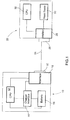
- FIG 1 is a schematic diagram of a mobile electronic device 10 connected to a Universal Serial Bus (USB) host 22.
- the mobile electronic device 10 includes a central processing unit (CPU) 12 that is coupled to a charger interface 14 which, in turn, is coupled to a rechargeable battery 16.
- the CPU 12 is also connected to the rechargeable battery 16 and to a USB interface 18 which is connected to a USB port 20.
- the charger interface 14 is connected to the USB interface 18.
- the USB interface 18 interacts with the USB port 20 to receive data and power from and transmit data to the USB host 22.
- the user connects the mobile electronic device 10 to the USB host 22 via a USB cable 24.
- the USB cable 24 is connected to a USB host port 26.
- a device interface 28 is connected to the USB host port 26 for transmitting data and power to and receiving data from the mobile electronic device 10.
- the USB host 22 further includes a power source 30 and a USB host CPU 32 which are both connected to the device interface 28.
- the power source 30 provides the requested power, in the form of a current/voltage, to the mobile electronic device while the USB host CPU 32 acknowledges enumeration and transmits a device suspend state request or signal, when required.
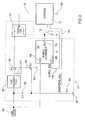
- the charger interface 14 which receives a USB VBUS input 48, includes a low dropout (LDO) regulator 50, a battery charger 52 and a DIODE OR 54.
- the LDO regulator 50 is connected to the DIODE OR 54 via a P field effect transistor (PFET) 56 with a corresponding pull-up resistor 57.
- the interface 14 further includes a capacitor 58 which is connected to ground 60 via two separate paths. One path to ground is via an N field effect transistor (FET) 62 and a second path to ground is via a resistor 64.
- the PFET 56 is also connected to ground 60 via the NFET 62.
- the battery charger 52 including a Vcc port 66, a charger enable (CE) port 68 and a battery (BAT) port 70, has its BAT port 70 connected to the rechargeable battery 16 and the DIODE OR 54.
- An output 72 of the DIODE OR 54 is connected to the system (e.g, the CPU) 12.
- a first output 74 from the CPU 12 is connected to the CE port 68 of the battery charger 52 for enabling and disabling the charger 52 while a second output 76 from the CPU 12 is connected to ground 60 via the resistor 64 along with to the LDO regulator 50 via the capacitor 58.
- the power source 30 transmits a current via the power line of the USB cable 24 to the charger interface 14 which is seen in Figure 2 as the USB VBUS input 48.
- a continuous check is performed by the mobile electronic device until the rising edge of the input 48 is sensed.
- the input 48 is transmitted to the Vcc port 66 of the battery charger 52, to the NFET 62 via the capacitor 58, and to the LDO regulator 50 in order to enable a battery charger power path and a LDO regulator power path (step 102).
- the capacitor 58 passes the rising edge of the VBUS input 48 to the gate of the NFET 62, which drives the NFET 62 to close the PFET 56 allowing the VBUS input 48 to through the LDO regulator 50 and the PFET 56 to the DIODE OR 54.
- the battery charger 52 may remain disabled until it receives instructions from the CPU 12 to enable. Transmission of the input 48 to ground 60 via the capacitor 58 and the resistor 64 enables a timer.
- the values of the capacitor 58 and the resistor 64 are selected so that they form a 100 msec timer as required by USB specifications.
- the CPU 12 transmits the first output 74, in the form of a low state signal, to the CE port 68 of the battery charger 52 to disable the power path provided by the battery charger 52.
- the DIODE OR 54 selects a power path and transmits the power supplied by this path to continually power the system 12.
- the DIODE OR 54 acts as a switch to select whether the system 12 receives its power from the LDO regulator 50 power path or the battery charger 52 power path.
- the DIODE OR 54 simply selects the higher of the two inputs as the power path.
- the LDO regulator is a 3.3V LDO regulator 50 so the DIODE OR 54 selects power from the LDO regulator 50 until the output voltage from the BAT port 70 reaches a level of 3.3 V.
- the output voltage from the BAT port 70 may be boosted by a voltage booster to increase the output of the BAT port 70 in order for the battery charger power path to be selected as the power path in a faster time period.
- the voltage from the battery charger 52 may be selected as the power path for the system 12, however, until the output voltage from the BAT port 70 of the battery charger 52 reaches a pre-determined level, the power path provided by the LDO regulator 50 allows the system to power up with little or no delay after the USB cable 24 is connected between the USB host 22 and the mobile electronic device 10.
- the system 12 Upon receipt of power from the DIODE OR 54, the system 12 powers up and responds to an enumeration request from the USB host CPU 32 within the USB host 22 via the data lines in the USB cable.
- the mobile electronic device 10 enters the device charging state. Once the enumeration acknowledgement is received by the system 12, the system transmits the first output 74, in the form of a high state signal, to the CE port 68 instructing the battery charger 52 to remain enabled.
- the second output 76 is also set to a level high after enumeration.
- the first output 74 is transmitted, in the form of a low state signal, from the system 12 to the CE port 68 of the battery charger 52 to disable the battery charger which, in turn, stops the BAT port 70 from both recharging the battery 16 and providing a power path for the system 12.
- the system 12 also transmits the second output 76, in the form of a low state signal, to the resistor 64 and the NFET 62 causing the NFET to drain, closing the PFET 56 and disabling the power path between the LDO regulator 50 and the DIODE OR 54. In this manner, there are no power paths entering the DIODE PR 54 and thus, no power provided to either recharge the battery or power up the device allowing the device to enter the device suspend state.
- SMPS switched mode power supply
- DIODE OR has been shown as the switching mechanism, other types of switches could also be used; for example circuits based on FETS or other transistors.
- NFET 62 and the PFET 56 are only one example for implementing a voltage controlled switch and other implementations are contemplated and possible.
- the capacitor and the NFET may be replaced by a voltage detector integrated circuit so that the alternate power path is enabled on the rising edge of the VBUS input for a time period of approximately 100 msec and so that the system can receive enumeration acknowledgement from the CPU 32 in the USB host 22 to complete the enumeration process.
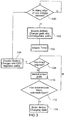
- FIG. 3 is a flow diagram of an example method of handling a charging state in a mobile electronic device.
- the mobile device monitors the USB VBUS input for a rising edge.
- the method proceeds to step 102 to enable the battery charger path and LDO regulator path.
- the timer is then enabled at step 104.
- the method determines if the timer has expired at step 106. If the timer has expired, then the battery charger and the LDO regulator paths are disabled at step 108, and the method returns to step 100. Else, if the timer has not expired, then the method proceeds to step 110 to select either the LDO or the battery charger as the power path for the mobile device.
- the DIODE OR 54 described above with reference to Figure 2 , may be used to select the power path with the highest voltage level.
- the method determines if a USB enumeration has been acknowledged. If not, then the method returns to step 106. Else, if a USB enumeration has been acknowledged, then the device may enter a charging state. For example, with reference to Figure 2 , the BAT output of the battery charger 52 may be enabled causing the DIODE OR 64 to select the BAT output as the power path for the mobile device.
- FIG. 4 is a flow diagram of another example method of handling a charging state in a mobile electronic device.
- the mobile device monitors the USB VBUS input for a rising edge.
- the method proceeds to step 202 to enable the LDO regulator. While enabled, the LDO regulator may be used to power the mobile device.
- a timer is then enabled at step 204.
- the mobile device monitors the USB host for an enumeration acknowledgement. If the timer expires (step 206) before an enumeration acknowledgement has been received from the USB host, then the LDO regulator is disabled at step 208 causing the mobile device to stop drawing power from the USB VBUS, and the method returns to step 200. If enumeration is acknowledged before the timer expires, however, then the method proceeds to step 214 to enable the battery charger, disable the LDO regulator and enter a device charging state.
- the mobile device monitors the USB host for a device suspend request. If a device suspend request is received, then the charger is disabled at step 218 and the method returns to step 200.
- Embodiments of the present invention may relate to one or more of the following enumerated example embodiments.
Landscapes
- Engineering & Computer Science (AREA)
- Theoretical Computer Science (AREA)
- General Engineering & Computer Science (AREA)
- Power Engineering (AREA)
- Physics & Mathematics (AREA)
- General Physics & Mathematics (AREA)
- Computer Hardware Design (AREA)
- Charge And Discharge Circuits For Batteries Or The Like (AREA)
- Power Sources (AREA)
Applications Claiming Priority (2)
| Application Number | Priority Date | Filing Date | Title |
|---|---|---|---|
| US54543304P | 2004-02-17 | 2004-02-17 | |
| EP04802384A EP1723494A4 (fr) | 2004-02-17 | 2004-12-30 | Procede et appareil de gestion de l'etat de charge dans un dispositif electronique mobile |
Related Parent Applications (1)
| Application Number | Title | Priority Date | Filing Date |
|---|---|---|---|
| EP04802384.0 Division | 2004-12-30 |
Publications (2)
| Publication Number | Publication Date |
|---|---|
| EP2562618A2 true EP2562618A2 (fr) | 2013-02-27 |
| EP2562618A3 EP2562618A3 (fr) | 2013-05-22 |
Family
ID=34860521
Family Applications (2)
| Application Number | Title | Priority Date | Filing Date |
|---|---|---|---|
| EP12193148.9A Withdrawn EP2562618A3 (fr) | 2004-02-17 | 2004-12-30 | Procédé et appareil de gestion de l'état de charge dans un dispositif électronique mobile |
| EP04802384A Withdrawn EP1723494A4 (fr) | 2004-02-17 | 2004-12-30 | Procede et appareil de gestion de l'etat de charge dans un dispositif electronique mobile |
Family Applications After (1)
| Application Number | Title | Priority Date | Filing Date |
|---|---|---|---|
| EP04802384A Withdrawn EP1723494A4 (fr) | 2004-02-17 | 2004-12-30 | Procede et appareil de gestion de l'etat de charge dans un dispositif electronique mobile |
Country Status (4)
| Country | Link |
|---|---|
| US (2) | US7679316B2 (fr) |
| EP (2) | EP2562618A3 (fr) |
| CA (1) | CA2556446C (fr) |
| WO (1) | WO2005078555A1 (fr) |
Families Citing this family (43)
| Publication number | Priority date | Publication date | Assignee | Title |
|---|---|---|---|---|
| GB2402271B (en) | 2003-05-27 | 2006-04-19 | Research In Motion Ltd | Method and apparatus for handling a charging state in a mobile electronic device |
| US7663338B2 (en) * | 2004-02-17 | 2010-02-16 | Research In Motion Limited | Method and apparatus for handling a charging state in a mobile electronic device |
| US20070241721A1 (en) * | 2005-03-21 | 2007-10-18 | Eveready Battery Company, Inc. | Direct current power supply |
| US7489105B2 (en) * | 2005-03-21 | 2009-02-10 | Eveready Battery Company, Inc. | Portable power supply |
| US7711039B2 (en) * | 2005-04-01 | 2010-05-04 | Freescale Semiconductor, Inc. | System and method for protecting low voltage transceiver |
| JP2007068333A (ja) * | 2005-08-31 | 2007-03-15 | Sony Corp | 電源供給専用装置,端末,電源供給システム,および電源供給方法 |
| US7834591B2 (en) * | 2006-02-16 | 2010-11-16 | Summit Microelectronics, Inc. | Switching battery charging systems and methods |
| US7880445B2 (en) * | 2006-02-16 | 2011-02-01 | Summit Microelectronics, Inc. | System and method of charging a battery using a switching regulator |
| US7531986B2 (en) * | 2006-02-23 | 2009-05-12 | Eveready Battery Company, Inc. | Power supply for battery powered devices |
| EP1860751A1 (fr) * | 2006-05-26 | 2007-11-28 | ASUSTeK Computer Inc. | Procédé et appareil de charge commandés par ordinateur pour convertir une puissance d'entrée en tension et courant nécessaire |
| US8018834B2 (en) | 2006-06-28 | 2011-09-13 | Nokia Corporation | Methods and devices for wire-based configuration of wireless devices |
| US8030900B2 (en) * | 2006-09-05 | 2011-10-04 | Summit Microelectronics, Inc. | Circuits and methods for controlling power in a battery operated system |
| WO2008038057A1 (fr) * | 2006-09-26 | 2008-04-03 | Nokia Corporation | Procédé et dispositif pour activer des fonctions d'un dispositif hors tension via une interface de bus de données série |
| CN101611524B (zh) * | 2007-01-25 | 2013-12-11 | 永备电池有限公司 | 便携式电源供应 |
| CN101589557B (zh) * | 2007-01-25 | 2014-05-07 | 永备电池有限公司 | 应用扩展器设备 |
| EP2115848A4 (fr) * | 2007-02-14 | 2013-01-23 | Rech Et Dev Everon Ca Inc | Système et procédé de recharge d'un dispositif mobile immergé |
| US20080231226A1 (en) * | 2007-03-23 | 2008-09-25 | Eveready Battery Company, Inc. | Battery Powered Device |
| US7728550B2 (en) * | 2007-07-20 | 2010-06-01 | Newport Media, Inc. | Integrated CMOS DC-DC converter implementation in low-voltage CMOS technology using LDO regulator |
| JP5152785B2 (ja) * | 2008-01-28 | 2013-02-27 | ソニーオプティアーク株式会社 | 周辺機器、周辺機器の動作方法、電子機器システム |
| TW201012024A (en) * | 2008-09-08 | 2010-03-16 | Richtek Technology Corp | Battery system and controlling method thereof and the charger for the battery system |
| US20100133908A1 (en) * | 2008-11-28 | 2010-06-03 | Lite-On It Corp. | Usb device with internal assisting power |
| US8546977B2 (en) * | 2009-04-22 | 2013-10-01 | Lsi Corporation | Voltage based switching of a power supply system current |
| US20110309789A1 (en) * | 2010-06-21 | 2011-12-22 | Kyocera Wireless Corp | Charger with data storage |
| CN101887530B (zh) * | 2010-07-07 | 2013-11-06 | 中兴通讯股份有限公司 | 一种带电池数据卡的开关装置及其节电的实现方法 |
| US8321603B2 (en) | 2010-07-28 | 2012-11-27 | Freescale Semiconductor, Inc. | Rechargeable device and method for determining universal serial bus port type |
| JP5812502B2 (ja) * | 2010-08-24 | 2015-11-17 | マーベル ワールド トレード リミテッド | デバイスインターフェース及び装置 |
| CN101980414A (zh) * | 2010-11-23 | 2011-02-23 | 苏州竞立制氢设备有限公司 | 两直流电源互为补充用供电装置 |
| US20120151121A1 (en) * | 2010-12-14 | 2012-06-14 | Jose Antonio Braga | Solid State Non-Volatile Storage Drives Having Self-Erase and Self-Destruct Functionality and Related Methods |
| US8552703B2 (en) | 2011-03-04 | 2013-10-08 | Intersil Americas Inc. | Method and apparatus for low standby current switching regulator |
| CN102202117B (zh) * | 2011-04-22 | 2015-01-28 | 中兴通讯股份有限公司 | 一种具有usb接口的电子设备及其usb通信启动方法 |
| US9120132B2 (en) * | 2011-11-09 | 2015-09-01 | ZZ Ventures, LLC | Pallet washing apparatus |
| CN102749980B (zh) * | 2012-05-25 | 2016-12-14 | 深圳Tcl新技术有限公司 | Usb主设备待机时为外部usb设备充电的方法及系统 |
| JP6288913B2 (ja) * | 2012-12-28 | 2018-03-07 | キヤノン株式会社 | 電子機器及びプログラム |
| JP5956966B2 (ja) * | 2013-09-06 | 2016-07-27 | 株式会社東芝 | 充電制御回路および充電制御システム |
| CN103475068B (zh) * | 2013-09-30 | 2016-03-23 | 小米科技有限责任公司 | 一种充电器、充电终端、充电系统及充电控制方法 |
| JP6277866B2 (ja) * | 2014-05-28 | 2018-02-14 | セイコーエプソン株式会社 | 充電装置及び電子機器 |
| CN109308111B (zh) * | 2014-05-28 | 2022-03-01 | 精工爱普生株式会社 | 电子设备 |
| US9917457B2 (en) | 2015-02-02 | 2018-03-13 | Black & Decker Inc. | Power tool with USB connection |
| CN114500709A (zh) | 2015-04-03 | 2022-05-13 | 品诺有限公司 | 个人无线媒体站 |
| JP6532357B2 (ja) * | 2015-08-31 | 2019-06-19 | キヤノン株式会社 | 送電装置、制御方法及びプログラム |
| US10079500B2 (en) * | 2016-06-20 | 2018-09-18 | Lenovo (Singapore) Pte. Ltd. | Apparatus, method, and program product for powering a device using a USB connection |
| JP2018116648A (ja) * | 2017-01-20 | 2018-07-26 | キヤノン株式会社 | 情報処理装置、その制御方法、及びプログラム |
| JP2019103218A (ja) * | 2017-11-30 | 2019-06-24 | ルネサスエレクトロニクス株式会社 | バッテリ装置および当該バッテリ装置において実行されるプログラム |
Family Cites Families (43)
| Publication number | Priority date | Publication date | Assignee | Title |
|---|---|---|---|---|
| US3748386A (en) * | 1972-04-03 | 1973-07-24 | D Monney | Time-base error correction system |
| US4568096A (en) * | 1984-04-19 | 1986-02-04 | General Motors Corporation | Automatic vehicle level control |
| US5028859A (en) * | 1989-06-05 | 1991-07-02 | Motorola, Inc. | Multiple battery, multiple rate battery charger |
| US5250891A (en) * | 1991-05-13 | 1993-10-05 | Milwaukee Electric Tool Corporation | Battery charging method and apparatus |
| US6008732A (en) * | 1992-12-31 | 1999-12-28 | Lam; Peter Ar-Fu | Motor vehicle display apparatus |
| JP2959657B2 (ja) * | 1993-05-13 | 1999-10-06 | キヤノン株式会社 | 電子機器 |
| US5519346A (en) | 1994-06-22 | 1996-05-21 | Motorola, Inc. | Selective restart circuit for an electronic device |
| AU7529994A (en) * | 1994-09-01 | 1996-03-22 | Tangdu Hospital Of Shaanxi Province | Ultra-high-frequency beauty device |
| JP3733554B2 (ja) * | 1994-10-31 | 2006-01-11 | 富士通株式会社 | バッテリ駆動型電子機器 |
| US5572110A (en) * | 1994-12-15 | 1996-11-05 | Intel Corporation | Smart battery charger system |
| US5798702A (en) * | 1996-04-18 | 1998-08-25 | Suzuki Motor Corporation | Residual battery capacity display device for electric vehicle |
| GB9623612D0 (en) * | 1996-11-13 | 1997-01-08 | Rca Thomson Licensing Corp | Separate power supplies for standby operation |
| US6357011B2 (en) * | 1998-07-15 | 2002-03-12 | Gateway, Inc. | Bus-powered computer peripheral with supplement battery power to overcome bus-power limit |
| US6532425B1 (en) * | 1998-09-18 | 2003-03-11 | C&D Charter Holdings, Inc. | Remote battery plant monitoring system |
| JP2000105638A (ja) * | 1998-09-29 | 2000-04-11 | Nec Corp | Usbデバイス及びusb接続システム |
| SE516285C2 (sv) * | 1999-01-27 | 2001-12-10 | Ericsson Telefon Ab L M | Ett förfarande som möjliggör kommunikation mellan en elektronisk anordning och ett batteri, en apparat som innefattar en elektronisk anordning och ett batteri, samt ett batteri som möjliggör kommunikation |
| US6211649B1 (en) * | 1999-03-25 | 2001-04-03 | Sourcenext Corporation | USB cable and method for charging battery of external apparatus by using USB cable |
| US6031362A (en) * | 1999-05-13 | 2000-02-29 | Bradley; Larry D. | Method and apparatus for feedback control of switch mode power supply output to linear regulators |
| US6153855A (en) * | 1999-05-20 | 2000-11-28 | Illinois Tool Works Inc. | Control of weld and auxiliary power output of a generator type welding power supply |
| US6633932B1 (en) * | 1999-09-14 | 2003-10-14 | Texas Instruments Incorporated | Method and apparatus for using a universal serial bus to provide power to a portable electronic device |
| DE19944053C2 (de) * | 1999-09-14 | 2001-08-02 | Infineon Technologies Ag | Vorrichtung und Verfahren zur Stromversorgung von Rechner-Zusatzgeräten über das Bussystem des Rechners |
| US6586940B2 (en) * | 2000-03-13 | 2003-07-01 | Nippon Telegraph And Telephone Corporation | Capacity estimation method, degradation estimation method and degradation estimation apparatus for lithium-ion cells, and lithium-ion batteries |
| GB2362769A (en) * | 2000-05-26 | 2001-11-28 | Nokia Mobile Phones Ltd | Battery charging circuit in which power is supplied via a communications port |
| TW479393B (en) * | 2000-09-27 | 2002-03-11 | Acer Peripherals Inc | Automatic USB charging apparatus and its operating method |
| US6883715B1 (en) * | 2000-10-11 | 2005-04-26 | Stmicroelectronics, Inc. | Multi-mode smart card, system and associated methods |
| EP1198049A1 (fr) | 2000-10-12 | 2002-04-17 | Sony International (Europe) GmbH | Circuit de charge pour le chargement d'une unité mobile utilisant un interface BSU |
| WO2002071734A2 (fr) * | 2000-12-19 | 2002-09-12 | Smal Camera Technologies, Inc. | Système d'appareil photo numérique compact |
| CA2374342C (fr) * | 2001-03-01 | 2005-12-20 | Research In Motion Limited | Systeme et methode d'alimentation et de charge d'un dispositif de communication mobile |
| US6936936B2 (en) * | 2001-03-01 | 2005-08-30 | Research In Motion Limited | Multifunctional charger system and method |
| US6507172B2 (en) * | 2001-03-19 | 2003-01-14 | Maxim Integrated Products, Inc. | Universal serial bus powered battery charger |
| US6531854B2 (en) * | 2001-03-30 | 2003-03-11 | Champion Microelectronic Corp. | Power factor correction circuit arrangement |
| US6812971B2 (en) * | 2001-09-11 | 2004-11-02 | Olympus Optical Co., Ltd. | Electronic apparatus, stand and electronic apparatus stand system |
| TW529243B (en) * | 2001-10-22 | 2003-04-21 | Winbond Electronics Corp | Power initiation apparatus of peripheral device |
| US20030110403A1 (en) * | 2001-12-10 | 2003-06-12 | Intel Corporation | System for shared power supply in computer peripheral devices |
| TW543994U (en) * | 2001-12-25 | 2003-07-21 | Sheng-Shing Liau | Easy carrying multi-function charger |
| JP3904489B2 (ja) * | 2002-07-04 | 2007-04-11 | 富士通株式会社 | 充電制御回路、充電器、電源回路、及び情報処理装置、並びに電池パック |
| JP3654274B2 (ja) * | 2002-08-30 | 2005-06-02 | セイコーエプソン株式会社 | データ転送制御装置、電子機器及び電源切替方法 |
| US6650089B1 (en) * | 2002-10-16 | 2003-11-18 | Texas Instruments Incorporated | Control circuit for multiple battery systems with capacity gauge on end equipment |
| US6833686B2 (en) * | 2003-02-21 | 2004-12-21 | Research In Motion Limited | Circuit and method of operation for an adaptive charge rate power supply |
| GB2402271B (en) * | 2003-05-27 | 2006-04-19 | Research In Motion Ltd | Method and apparatus for handling a charging state in a mobile electronic device |
| GB2402819B (en) * | 2003-06-11 | 2005-08-03 | Research In Motion Ltd | Universal serial bus charger for a mobile device |
| JP4078553B2 (ja) * | 2003-10-21 | 2008-04-23 | 新神戸電機株式会社 | 車両用リチウム電池モジュール |
| US7663338B2 (en) * | 2004-02-17 | 2010-02-16 | Research In Motion Limited | Method and apparatus for handling a charging state in a mobile electronic device |
-
2004
- 2004-12-30 CA CA2556446A patent/CA2556446C/fr not_active Expired - Lifetime
- 2004-12-30 US US11/026,590 patent/US7679316B2/en active Active
- 2004-12-30 EP EP12193148.9A patent/EP2562618A3/fr not_active Withdrawn
- 2004-12-30 WO PCT/CA2004/002209 patent/WO2005078555A1/fr not_active Ceased
- 2004-12-30 EP EP04802384A patent/EP1723494A4/fr not_active Withdrawn
-
2010
- 2010-01-19 US US12/689,587 patent/US7847517B2/en not_active Expired - Lifetime
Non-Patent Citations (1)
| Title |
|---|
| None |
Also Published As
| Publication number | Publication date |
|---|---|
| EP1723494A4 (fr) | 2010-09-29 |
| CA2556446A1 (fr) | 2005-08-25 |
| US20050189909A1 (en) | 2005-09-01 |
| EP2562618A3 (fr) | 2013-05-22 |
| US7679316B2 (en) | 2010-03-16 |
| US7847517B2 (en) | 2010-12-07 |
| CA2556446C (fr) | 2011-02-08 |
| EP1723494A1 (fr) | 2006-11-22 |
| US20100117595A1 (en) | 2010-05-13 |
| WO2005078555A1 (fr) | 2005-08-25 |
Similar Documents
| Publication | Publication Date | Title |
|---|---|---|
| US7679316B2 (en) | Method and apparatus for controlling a charging state in a mobile electronic device | |
| US7518343B2 (en) | Method and apparatus for handling a charging state in a mobile electronic device | |
| EP1723493B1 (fr) | Procede et appareil de gestion d'un etat de charge dans un dispositif electronique mobile | |
| CN101071955B (zh) | 电源系统以及电子设备 | |
| JPH08308121A (ja) | バッテリパックおよびその動作モードの制御方法並びに電子機器 | |
| CN103166251A (zh) | 备用电池充电电路 | |
| CN110875618B (zh) | 半导体设备和操作半导体设备的方法 | |
| CN108879880A (zh) | 备用电池充电电路 | |
| HK1094049B (en) | Method and apparatus for handling a charging state in a mobile electronic device | |
| HK1071234B (en) | Method and apparatus for controlling the charging state in a mobile electronic device | |
| HK1206826B (en) | Method and apparatus for handling a charging state in a mobile electronic device |
Legal Events
| Date | Code | Title | Description |
|---|---|---|---|
| PUAI | Public reference made under article 153(3) epc to a published international application that has entered the european phase |
Free format text: ORIGINAL CODE: 0009012 |
|
| 17P | Request for examination filed |
Effective date: 20121119 |
|
| AC | Divisional application: reference to earlier application |
Ref document number: 1723494 Country of ref document: EP Kind code of ref document: P |
|
| AK | Designated contracting states |
Kind code of ref document: A2 Designated state(s): AT BE BG CH CY CZ DE DK EE ES FI FR GB GR HU IE IS IT LI LT LU MC NL PL PT RO SE SI SK TR |
|
| AX | Request for extension of the european patent |
Extension state: AL BA HR LV MK YU |
|
| PUAL | Search report despatched |
Free format text: ORIGINAL CODE: 0009013 |
|
| AK | Designated contracting states |
Kind code of ref document: A3 Designated state(s): AT BE BG CH CY CZ DE DK EE ES FI FR GB GR HU IE IS IT LI LT LU MC NL PL PT RO SE SI SK TR |
|
| AX | Request for extension of the european patent |
Extension state: AL BA HR LV MK YU |
|
| RIC1 | Information provided on ipc code assigned before grant |
Ipc: H02J 7/00 20060101ALI20130416BHEP Ipc: G06F 13/38 20060101ALI20130416BHEP Ipc: G06F 1/26 20060101AFI20130416BHEP Ipc: G06F 1/28 20060101ALI20130416BHEP |
|
| RAP1 | Party data changed (applicant data changed or rights of an application transferred) |
Owner name: BLACKBERRY LIMITED |
|
| STAA | Information on the status of an ep patent application or granted ep patent |
Free format text: STATUS: THE APPLICATION HAS BEEN WITHDRAWN |
|
| RAP1 | Party data changed (applicant data changed or rights of an application transferred) |
Owner name: BLACKBERRY LIMITED |
|
| 18W | Application withdrawn |
Effective date: 20131118 |