EP2562714A1 - Bildabtastvorrichtung, Steuerverfahren und zugehöriges Programm - Google Patents
Bildabtastvorrichtung, Steuerverfahren und zugehöriges Programm Download PDFInfo
- Publication number
- EP2562714A1 EP2562714A1 EP12187482A EP12187482A EP2562714A1 EP 2562714 A1 EP2562714 A1 EP 2562714A1 EP 12187482 A EP12187482 A EP 12187482A EP 12187482 A EP12187482 A EP 12187482A EP 2562714 A1 EP2562714 A1 EP 2562714A1
- Authority
- EP
- European Patent Office
- Prior art keywords
- view
- image
- angle
- readout
- horizontal
- Prior art date
- Legal status (The legal status is an assumption and is not a legal conclusion. Google has not performed a legal analysis and makes no representation as to the accuracy of the status listed.)
- Withdrawn
Links
Images


Classifications
-
- G—PHYSICS
- G06—COMPUTING OR CALCULATING; COUNTING
- G06T—IMAGE DATA PROCESSING OR GENERATION, IN GENERAL
- G06T3/00—Geometric image transformations in the plane of the image
- G06T3/40—Scaling of whole images or parts thereof, e.g. expanding or contracting
- G06T3/4023—Scaling of whole images or parts thereof, e.g. expanding or contracting based on decimating pixels or lines of pixels; based on inserting pixels or lines of pixels
-
- H—ELECTRICITY
- H04—ELECTRIC COMMUNICATION TECHNIQUE
- H04N—PICTORIAL COMMUNICATION, e.g. TELEVISION
- H04N23/00—Cameras or camera modules comprising electronic image sensors; Control thereof
- H04N23/60—Control of cameras or camera modules
- H04N23/69—Control of means for changing angle of the field of view, e.g. optical zoom objectives or electronic zooming
Definitions
- the present invention relates to an electronic zoom technique of reducing the degradation of resolution.
- Recent advanced image sensing elements have significantly developed image input devices including an electronic still camera and video camera.
- electronic still cameras and video cameras with a movie function have been proposed.
- a camera of this type has an electronic zoom function of extracting only signals of a desired range from image signals read out from an image sensing element, and enlarging the image of the extracted signal to zoom electronically.
- the electronic zoom function is designed to make the readout pixel count almost equal to the output pixel count for display and recording at the widest angle of view. As the camera zooms in, the readout pixel count runs short compared to the output pixel count, degrading the resolution. As solutions to this, the following methods have been proposed.
- the first method provides an electronic zoom which hardly degrades the resolution.
- signals are always read out from all the pixels (e.g., 1,280 x 960) of a region corresponding to the widest angle of view.
- some of the readout signals are extracted and directly read out (e.g., 640 x 480 for a 2x zoom).
- signals are output by reducing the pixel count by conversion (in this case, reduction conversion from 1,280 x 960 to 640 x 480).
- the first method needs to always read out signals from all the pixels (1,280 x 960), decreasing the display frame rate (to 1/4 of the frame rate to read out signals from 640 x 480 pixels).
- the second method is an electronic zoom method which makes the readout pixel count almost equal to the output pixel count for display and recording, reducing the degradation of resolution, like Japanese Patent Laid-Open No. 2000-295530 .
- this method for example, when a 2x zoom function is activated, signals are read out from all the 640 x 480 pixels of an extracted region for a telephoto angle of view. For a wide angle of view, signals are read out from 640 x 480 pixels out of the entire 1,280 x 960 region while thinning them at a thinning rate of 1/2 vertically and horizontally. The entire 1,280 x 960 region is used to, for example, shoot a still image.
- the second method can take only discrete magnifications capable of thinning readout.
- images can only be shot at discrete magnifications.
- the third method is an electronic zoom method of gradually changing the thinning rate of image signals output from an image sensing element, instead of simple thinning, in order to attain an intermediate magnification, like Japanese Patent Laid-Open No. 2005-191867 .
- This method reads out image signals from n pixels out of m pixels (m ⁇ n; m and n are natural numbers) at a thinning rate n/m. Changing n/m implements an intermediate magnification.
- the third method can provide an intermediate magnification by gradually changing the thinning rate of image signals.
- this method needs to always read out signals from all the pixels and suffers a low display frame rate, similar to the first method.
- Japanese Patent Laid-Open No. 2002-330329 proposes the fourth method. According to this method, images of the predetermined size necessary for display are read out from a region D and larger region E at a thinning rate d and higher thinning rate e. For an intermediate region between the regions D and E, an image is read out from the region E at the thinning rate d, and converted into the predetermined image size necessary for display using the image size of the intermediate region out of the readout image. As a result, an electronic zoom at an intermediate magnification is achieved. Note that thinning to 1/e is expressed as a thinning rate e in Japanese Patent Laid-Open No. 2002-330329 , and will be defined as a thinning rate of 1/e in this specification.
- the fourth method attains an electronic zoom by reading out an image from the region D at the thinning rate d, and even for an intermediate region between the regions D and E, reading out an image from the region E at the thinning rate d.
- the readout image size (pixel count) of the region E becomes the square of e/d of the readout image size (pixel count) of the region D.
- the readout time of the region E also becomes the square of e/d of the readout time of the region D, and limits the frame rate in movie shooting.
- an image is read out from a 10 x 10 pixel region at a thinning rate of 1, and read out from a 20 x 20 pixel region at a thinning rate of 2.
- an image is read out from the 20 x 20 pixel region at a thinning rate of 1.
- the readout pixel count becomes the square of 2/1, that is, quadruples.
- the readout time is unbalanced between readout of the region E and that of the region D.
- the readout time of a shot image differs between regions.
- the readout timing of the first pixel (1st pixel) in the 10 x 10 pixel region and that of the first pixel (1st pixel) in the 20 x 20 pixel region differ from each other by a time corresponding to readout of 300 pixels.
- the readout timing of the final pixel (100th pixel) in the 10 x 10 pixel region and that of the final pixel (400th pixel) in the 20 x 20 pixel region differ from each other by a time corresponding to readout of 300 pixels.
- Japanese Patent Laid-Open No. 2002-330329 describes a technique of reading out an image from a region corresponding to a desired intermediate magnification by changing the readout method of pixels from an image sensing element while implementing an image size necessary for display at the intermediate magnification by the same method as the third one.
- the present invention in its first aspect provides an image sensing apparatus as specified in claims 1 to 6.
- the present invention in its second aspect provides a control method of an image sensing apparatus as specified in claims 7 to 10.
- the present invention in its third aspect provides a program according to claims 11 and 12.
- a program can be provided by itself or carried by a carrier medium as specified in claim 13.
- the carrier medium may be a recording or other storage medium.
- the carrier medium may also be a transmission medium.
- the transmission medium may be a signal.
- an electronic zoom technique of smoothly operating the electronic zoom without greatly degrading the resolution or complicating control can be provided.
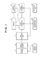
- Fig. 1 is a block diagram showing the arrangement of an image sensing apparatus according to an embodiment of the present invention
- Fig. 2 is a block diagram showing the detailed arrangement of a signal processing unit in Fig. 1 ;
- Fig. 3 is a block diagram showing the detailed arrangement of an image sensing element in Fig. 1 ;
- Fig. 4 is a circuit diagram showing the detailed structure of the pixel of the image sensing element
- Fig. 5 is a circuit diagram showing the detailed arrangements of an addition circuit and horizontal readout circuit in Fig. 3 ;
- Fig. 6 is a view exemplifying an image read out from all the pixels of the image sensing element while thinning them at a thinning rate of 1/3;
- Fig. 7 is a view exemplifying an image read out from pixels corresponding to a 1.56x angle of view in Fig. 6 while thinning them at a thinning rate of 1/2;
- Fig. 8 is a view exemplifying an image read out from pixels corresponding to a 2.34x angle of view in Fig. 7 one by one in the horizontal and vertical directions;
- Fig. 9 is a view exemplifying an image read out from all the pixels of the image sensing element while thinning them at a thinning rate of 1/3;
- Fig. 10 is a view exemplifying an image read out from pixels corresponding to a 1.39x angle of view in Fig. 9 while thinning them at a thinning rate of 1/2;
- Fig. 11 is a view exemplifying an image read out from pixels corresponding to a 2.14x angle of view in Fig. 10 one by one in the horizontal and vertical directions.
- An image sensing apparatus is implemented by an electronic still camera or video camera with a movie function, and includes a megapixel image sensing element, an image display unit capable of displaying an image sensed by the image sensing element, and an image recording unit capable of recording the image.
- the image sensing apparatus is premised on that a pixel count used to display and record a movie is smaller than that used to record a still image.
- Fig. 1 is a block diagram showing the arrangement of the image sensing apparatus according to the first embodiment.
- the image sensing apparatus of the embodiment includes an optical system 1, an image sensing element 2, a driving circuit 3, a pre-processing unit 4, a signal processing unit 5, a memory 6 for storing image data, an image display unit 7, an image recording unit 8, an operation unit 9, and a synchronous control unit 10.
- the optical system 1 includes a focusing lens for forming an object image on the image sensing element 2, a zoom lens for optically zooming, a stop for adjusting the brightness of an object image, and a shutter for controlling exposure.
- the driving circuit 3 drives these components.
- the image sensing element 2 includes a plurality of pixels arrayed in a matrix, and a circuit for outputting signals read out from these pixels in a predetermined order. Details of the image sensing element 2 will be described later with reference to Fig. 3 .
- the driving circuit 3 drives the optical system 1 and image sensing element 2 by supplying a constant voltage and a pulse which enhances driving performance.
- the driving circuit 3 also has a function of transmitting a control signal from the synchronous control unit 10 to the image sensing element 2.
- the pre-processing unit 4 is controlled by a control signal from the synchronous control unit 10.
- the pre-processing unit 4 includes a correlated double sampling circuit (CDS circuit) for removing a noise component such as reset noise from an analog signal output from the image sensing element 2.
- the pre-processing unit 4 further includes a gain control amplifier for adjusting the amplitude of a noise-free signal, and an A/D converter for converting an amplitude-adjusted analog signal into a digital signal.
- CDS circuit correlated double sampling circuit
- the signal processing unit 5 is controlled by a control signal from the synchronous control unit 10.
- the signal processing unit 5 performs appropriate signal processing for an output signal which has been converted into a digital signal and sent from the pre-processing unit 4, and converts the processed signal into image data.
- the signal processing unit 5 outputs image data and an output signal converted into a digital signal to the memory 6 and image recording unit 8.
- the signal processing unit 5 executes signal processing upon receiving image data and an output signal converted into a digital signal from the memory 6 and image recording unit 8.
- the signal processing unit 5 also has a function of detecting photometric data such as a focusing state and exposure from a signal output from the image sensing element 2, and sending the data to the synchronous control unit 10.
- the memory 6 is controlled by a control signal from the synchronous control unit 10.
- the memory 6 temporarily stores a signal which has been output from the image sensing element 2 and converted into a digital signal, and image data having undergone signal processing.
- the memory 6 also has a function of outputting display image data to the image display unit 7.
- the image display unit 7 is controlled by a control signal from the synchronous control unit 10.
- the image display unit 7 displays display image data to be stored in the memory 6, in order to allow the user to decide the composition before shooting or confirm a shot image.
- the image display unit 7 is formed from an electronic viewfinder (EVF) and liquid crystal display (LCD).
- EMF electronic viewfinder
- LCD liquid crystal display
- the image display unit 7 has a display pixel count smaller than the vertical pixel count of the image sensing element 2.
- the display pixel count of the image display unit 7 is smaller than the output pixel count of the image sensing element 2.
- the image recording unit 8 includes a detachable memory and the like, and is controlled by a control signal from the synchronous control unit 10.
- the image recording unit 8 can record image data and an output signal which has been converted into a digital signal and sent from the signal processing unit 5, and read image data from the detachable memory.
- the operation unit 9 notifies the synchronous control unit 10 of an external instruction using operation members such as a switch, push button, lever, and dial.
- Examples of the external instruction are the state of the power switch of the image sensing apparatus, that of the push button for designating shooting, that of the button or lever for designating the optical zoom or electronic zoom, and that of the mode dial for selecting a shooting mode.
- the operation unit 9 notifies the synchronous control unit 10 of an image display instruction before shooting, various shooting instructions, and a menu operation to designate display of a shot image or the operation of the image sensing apparatus in advance.
- the operation unit 9 can display the state of the image sensing apparatus on a display (e.g., an LCD or LED) or the image display unit 7. It is also possible to use the image display unit 7 as a display and a touch panel attached to the image display unit 7 as an operation member, and perform an on-screen operation.
- the synchronous control unit 10 controls the overall image sensing apparatus based on an instruction input from the operation unit 9.
- the synchronous control unit 10 controls the optical system 1 to form an optimum object image on the image sensing element 2 in accordance with photometric data such as a focusing state and exposure sent from the signal processing unit 5.
- the synchronous control unit 10 can detect the use status of the memory 6 and the attachment and use status of the memory of the image recording unit 8.
- Fig. 2 is a block diagram exemplifying details of the signal processing unit 5 in Fig. 1 .
- the signal processing unit 5 includes an R interpolation circuit 91, G interpolation circuit 92, B interpolation circuit 93, white balance circuit 94, color signal correction circuit 95, gamma conversion circuit 96, and edge correction circuit 97.
- the signal processing unit 5 causes the R interpolation circuit 91, G interpolation circuit 92, and B interpolation circuit 93 to interpolate R, G, and B signals input from the pre-processing unit 4 and generate R, G, and B signals which are absent at corresponding pixel positions.
- the signal processing unit 5 causes the white balance circuit 94 to execute white balance adjustment, and the color signal correction circuit 95 to execute color signal processing including color noise removal and removal of a false color such as moire.
- the signal processing unit 5 causes the gamma conversion circuit 96 to perform gamma conversion, and the edge correction circuit 97 to perform luminance signal processing including edge enhancement and aperture correction, thereby completing a color image.
- the signal processing unit 5 sends the complete color image to the memory 6 and image recording unit 8.
- the R interpolation circuit 91, G interpolation circuit 92, and B interpolation circuit 93 may execute pixel count conversion corresponding to a still image, movie recording image, or display image.
- the signal processing unit 5 may include an image compression circuit to compress an image, output the compressed image to the image recording unit 8, and record it.
- the power supply is turned on in response to an instruction from the power switch of the operation unit 9.
- the signal processing unit 5 converts an image signal from the image sensing element 2 into display image data, and displays the image data on the image display unit 7. In addition, the signal processing unit 5 detects photometric data and sends it to the synchronous control unit 10.
- the synchronous control unit 10 controls the optical system 1 based on the photometric data.
- the signal processing unit 5 detects photometric data from an image signal from the image sensing element 2, and sends it to the synchronous control unit 10.
- the synchronous control unit 10 controls the optical system 1 based on the photometric data.
- the image sensing element 2 undergoes exposure for still image recording, and outputs a signal.
- the signal processing unit 5 converts the image signal from the image sensing element 2 into recording image data, and sends the data to the image recording unit 8 to record it in a detachable memory. Also, the signal processing unit 5 converts the recording image data into display image data, and displays it on the image display unit 7.
- the signal processing unit 5 converts an image signal from the image sensing element 2 into recording image data, and sends the data to the image recording unit 8 to record it in a detachable memory. Also, the signal processing unit 5 converts the recording image data into display image data, and displays it on the image display unit 7.
- the signal processing unit 5 detects photometric data from the image signal from the image sensing element 2, and sends it to the synchronous control unit 10.
- the synchronous control unit 10 controls the optical system 1 based on the photometric data.
- the image sensing element 2 undergoes exposure for still image recording, and outputs a signal.
- Control of the electronic zoom starts in response to an instruction from the zoom button or zoom lever of the operation unit 9 in (4) of ⁇ control of display image> or (5) of ⁇ control of movie shooting>.
- the synchronous control unit 10 decides an electronic zoom magnification, and switches driving of the image sensing element 2.
- the synchronous control unit 10 instructs the signal processing unit 5 on signal processing corresponding to the electronic zoom magnification.
- the pixel count is 12 in both the horizontal and vertical directions for descriptive convenience.
- a pixel 11 converts incident light into an electrical signal, and (1,1) is an address representing the horizontal position (H) and vertical position (V) of this pixel.
- the remaining pixels have the same structure as that of the pixel 11 except that corresponding vertical address lines 201 to 212 and vertical signal lines 101 to 112 differs between the pixels.
- (H,V) is an address representing the position of each pixel.
- Fig. 4 shows the detailed structure of the pixel 11.
- a portion surrounded by a dotted line is the pixel 11.
- the pixel 11 is connected to other circuits via the vertical address line 201 which is commonly connected to pixels on one horizontal row and can simultaneously control them, and the vertical signal line 101 which is commonly connected to pixels on one vertical column and outputs signals from them.
- the vertical address line 201 includes a reset control line 221, vertical address line 241, and transfer control line 261.
- a photoelectric conversion element D1 converts light into charges.
- An FD capacitor C1 accumulates charges when converting charges of the photoelectric conversion element D1 into a voltage.
- a driving transistor Td1 for an amplifier in a pixel outputs a voltage corresponding to the voltage of the FD capacitor C1.
- a reset transistor T1 is connected to the reset control line 221 to reset the voltage of the FD capacitor C1.
- a selection transistor T2 is connected to the vertical address line 241 to output an output from the driving transistor Td1 as the output signal of the pixel to the vertical signal line 101.
- a transfer transistor T3 is connected to the transfer control line 261 to control transfer of charges from the photoelectric conversion element D1 to the FD capacitor C1.
- a power supply Vd is used for the driving transistor Td1 and reset transistor T1.
- transistors other than the driving transistor Td1 function as switches, and are turned on upon activating the control line connected to their gates and off upon inactivating it.
- the vertical address line 201 controls all the pixels on one horizontal row.
- the pixel (1,1) will be exemplified, but the remaining pixels operate similarly.
- the transfer transistor T3 is OFF, the reset transistor T1 is turned on via the reset control line 221 to reset the voltage of the FD capacitor C1, and then turned off.
- the transfer transistor T3 is turned on via the transfer control line 261 to transfer charges from the photoelectric conversion element D1 to the FD capacitor C1.
- the charges transferred from the photoelectric conversion element D1 are converted into a voltage as a pixel signal.
- the selection transistor T2 is turned on via the vertical address line 241 to output the signal voltage of the FD capacitor C1 to the vertical signal line 101. This signal serves as a pixel signal, and this readout will be defined as pixel signal readout.
- a first readout angle 601 of view is the full angle of view containing all 12 x 12 pixels (1,1) to (12,12) in the horizontal and vertical directions.
- a second readout angle 602 of view contains 8 x 8 pixels (3,3) to (10,10) in the horizontal and vertical directions out of the full angle of view.
- a third readout angle 603 of view contains 4 x 4 pixels (5,5) to (8,8) in the horizontal and vertical out of the full angle of view.
- Six vertical shift registers 21 to 26 can select the vertical address lines 201 to 212 connected to readout pixels, and select the first readout angle 601 of view, second readout angle 602 of view, and third readout angle 603 of view.
- a vertical control circuit 33 receives a control signal from the synchronous control unit 10 via a control input terminal 16 to control the vertical shift registers 21 to 26.
- a vertical shift register control line 34 can designate one of "select every row”, “select every other row”, and “select every third row” via the vertical address lines 201 to 212.
- Reference numerals 35 to 37 denote vertical register selection lines.
- the vertical register selection line 35 selects all the vertical shift registers 21 to 26 to select pixels corresponding to the first readout angle 601 of view serving as the full angle of view.
- the vertical register selection line 36 selects the vertical shift registers 22 to 25 to select pixels corresponding to the second readout angle 602 of view.
- the vertical register selection line 37 selects the vertical shift registers 23 and 24 to select pixels corresponding to the third readout angle 603 of view.
- the vertical register selection lines 35 to 37 can instruct selected vertical shift registers on one of "one-row readout operation", "two-row addition operation”, and "three-row addition operation”.
- the vertical register selection lines 35 to 37 designate "one-row readout operation”
- the vertical shift register control line 34 designates one of "select every row”, “select every other row”, and “select every third row”.
- the vertical shift registers 21 to 26 can be controlled to "select every row”, “select every other row”, and "select every third row” via the vertical address lines 201 to 212 of a corresponding angle of view.
- the vertical register selection lines 35 to 37 designate "two-row addition operation”
- the vertical shift register control line 34 designates "select every other row”.
- the vertical shift registers 21 to 26 can be controlled to "simultaneously select two rows" via the vertical address lines 201 to 212 of a corresponding angle of view during the one-row readout operation. Then, the signals of two pixels in the vertical direction are averaged and output to the vertical address lines. Further, assume that the vertical register selection lines 35 to 37 designate "three-row addition operation", and the vertical shift register control line 34 designates "select every third row”. In this case, the vertical shift registers 21 to 26 can be controlled to "simultaneously select three rows” via the vertical address lines of a corresponding angle of view during the one-row readout operation. Then, the signals of three pixels in the vertical direction are averaged and output to the vertical address lines.
- An addition circuit 12 can add pixel signals sent to the vertical signal lines 101 to 112.
- An addition control circuit 40 controls the addition circuit 12 based on the instruction of a control signal from the synchronous control unit 10 via the control input terminal 16.
- Addition control lines 41 to 48 control the addition circuit 12.
- a horizontal readout circuit 13 is controlled by horizontal address lines 401 to 412 to output, to an output circuit 14, signals sent via addition output lines 301 to 312 of the addition circuit 12.
- the output circuit 14 includes a current amplifier circuit and voltage amplifier circuit. The output circuit 14 amplifies a signal output from the horizontal readout circuit 13 to an appropriate current or voltage, and outputs the amplified signal to the pre-processing unit 4 via an output terminal 15.
- a horizontal readout control line 501 controls the horizontal readout circuit 13.
- Six horizontal shift registers 61 to 66 can select the horizontal address lines 401 to 412, and select the first readout angle 601 of view, second readout angle 602 of view, and third readout angle 603 of view.
- a horizontal control circuit 73 controls the horizontal shift registers 61 to 66 in response to a control signal from the synchronous control unit 10 via the control input terminal 16.
- a horizontal shift register control line 74 can designate one of "select every column”, “select every other column", and “select every third column” via the horizontal address lines.
- Reference numerals 75 to 77 denote horizontal register selection lines.
- the horizontal register selection line 75 selects all the horizontal shift registers 61 to 66 to select pixels corresponding to the first readout angle 601 of view serving as the full angle of view.
- the horizontal register selection line 76 selects the horizontal shift registers 62 to 65 to select pixels corresponding to the second readout angle 602 of view.
- the horizontal register selection line 77 selects the horizontal shift registers 63 and 64 to select pixels corresponding to the third readout angle 603 of view.
- the horizontal shift register control line 74 designates one of "select every column”, “select every other column”, and “select every third column”.
- the horizontal shift registers 61 to 66 can be controlled to "select every column”, “select every other column”, and “select every third column” via the horizontal address lines of a corresponding angle of view.
- Fig. 5 shows the detailed arrangements of the addition circuit 12 and horizontal readout circuit 13. Although only an arrangement corresponding to six pixels on the left in Fig. 3 will be explained with reference to Fig. 5 , the same arrangement also applies to six pixels on the right.
- Transistors T41 to T48 function as switches which are connected/disconnected by turning them on/off via addition control lines 41 to 48 of the same numbers as those of the transistors T41 to T48.
- Accumulation capacitors C101 to C106 (or C107 to C112 (not shown)) accumulate pixel signals sent to the vertical signal lines 101 to 106 (or vertical signal lines 107 to 112).
- Addition output lines 301 to 306 (or 307 to 312) transfer outputs from the addition circuit 12.
- Accumulation capacitors C401 to C406 accumulate signals sent via the addition output lines 301 to 306 (or 307 to 312).
- Transistors T401 to T406 (or T407 to T412 (not shown)) function as switches which are connected/disconnected by turning them on/off via the address lines 401 to 406 (or address lines 407 to 412 (not shown)) of the same numbers as those of the transistors T401 to T406.
- the transistors T401 to T406 (or T407 to T412 (not shown)) can output signals to the output circuit 14 via the horizontal readout control line 501.
- the output circuit 14 is an amplifier having the horizontal readout control line 501 as an input.
- the output circuit 14 amplifies an input signal to a proper current or voltage, and outputs the amplified signal to the pre-processing unit 4 via the output terminal 15.
- the transistors T41 are turned on to accumulate pixel signals sent to the vertical signal lines 101 to 106 in the accumulation capacitors C101 to C106, and then turned off.
- the addition control lines 45 to 48 turn on the transistors T45 to T48.
- the signals in the accumulation capacitors C101 to C106 are output to the addition output lines 301 to 306, and accumulated in the corresponding accumulation capacitors C401 to C406 of the horizontal readout circuit 13. Thereafter, the transistors T45 to T48 are turned off.
- the transistors T401 to T406 are sequentially turned on/off under the control of the horizontal address lines 401 to 406.
- the signals in the accumulation capacitors C401 to C406 are sequentially output to the output circuit 14 via the horizontal readout control line 501.
- This operation is also executed for pixel signals sent to the vertical signal lines 107 to 112, sequentially outputting the pixel signals sent to the vertical signal lines 101 to 112.
- the transistors T43 and T44 are turned on under the control of the addition control lines 43 and 44, and the transistors T46 and T47 are turned on under the control of the addition control lines 46 and 47. Averaged signals of every two signals from the accumulation capacitors C101 to C106 are output to the corresponding addition output lines 301, 303, and 305.
- the transistor T43, T44, T46, and T47 are turned off.
- the transistors T401, T403, and T405 are turned on/off in order under the control of the horizontal address lines 401, 403, and 405.
- the signals in the accumulation capacitors C401, C403, and C405 are sequentially output to the output circuit 14 via the horizontal readout control line 501.
- This operation is also performed for pixel signals sent to the vertical signal lines 107 to 112, sequentially outputting signals in the accumulation capacitors C407, C409, and C411 to the output circuit 14 via the horizontal readout control line 501. Accordingly, signals obtained by adding pixel signals sent to the vertical signal lines 101 to 112 for every two pixels in the horizontal direction can be output.
- the transistors T42 and T44 are turned on under the control of the addition control lines 42 and 44, and the transistors T45 and T46 are turned on under the control of the addition control lines 45 and 46. Averaged signals of every three signals from the accumulation capacitors C101 to C106 are output to the corresponding addition output lines 301 and 304.
- the transistor T42, T44, T45, and T46 are turned off.
- the transistors T401 and T404 are turned on/off in order under the control of the horizontal address lines 401 and 404.
- the signals in the accumulation capacitors C401 and C404 are sequentially output to the output circuit 14 via the horizontal readout control line 501.
- This operation is also performed for signals sent to the vertical signal lines 107 to 112, sequentially outputting signals in the accumulation capacitors C407 and C410 to the output circuit 14 via the horizontal readout control line 501.
- signals obtained by adding pixel signals sent to the vertical signal lines 101 to 112 for every three pixels in the horizontal direction can be output.
- horizontal and vertical pixel thinning operations include 1/2 thinning in only the vertical direction, 1/3 thinning in only the vertical direction, 1/2 thinning in only the horizontal direction, 1/3 thinning in only the horizontal direction, 1/2 thinning in the horizontal and vertical directions, and 1/3 thinning in the horizontal and vertical directions.
- the pixel thinning operations include a combination of 1/2 thinning in the horizontal direction and 1/3 thinning in the vertical direction, and a combination of 1/3 thinning in the horizontal direction and 1/2 thinning in the vertical direction.
- the thinning rate can be set to 1/n (n is a natural number) in each of the horizontal and vertical directions.
- Horizontal and vertical pixel addition operations include addition of two pixels in only the vertical direction, addition of three pixels in only the vertical direction, addition of two pixels in only the horizontal direction, and addition of three pixels in only the horizontal direction.
- Selectable readout angles of view are three: the first readout angle 601 of view serving as the full angle of view, the second readout angle 602 of view, and the third readout angle 603 of view.
- the foregoing pixel addition operations and pixel thinning operations can be implemented.
- the pixel addition counts and pixel thinning counts in the horizontal and vertical directions can be increased to four or more pixels, and the number of readout angles of view can also be increased to more than three.
- a still image shooting mode in which signals are read out pixel by pixel from the first readout angle 601 of view serving as the full angle of view will be explained.
- This mode corresponds to (4) of ⁇ control of still image shooting>.
- signals are read out pixel by pixel in the horizontal and vertical directions from the first readout angle 601 of view serving as the full angle of view. For this purpose, the following selecting operations are performed.
- the vertical shift registers and horizontal shift registers select the first readout angle 601 of view serving as the full angle of view.
- the addition circuit 12 selects "horizontal addition-free operation".
- the vertical shift register control line 34 designates “select every row” in the image sensing element 2.
- the vertical register selection line 35 is selected, and "one-row readout operation" is designated.
- the first readout angle 601 of view serving as the full angle of view is selected, and the vertical address lines 201 to 212 are selected in order.
- This operation selects the vertical address line 201 first to read out pixel signals from the first row of the image sensing element 2 and output them to the corresponding vertical signal lines 101 to 112.
- the addition circuit 12 directly sends the pixel signals to the horizontal readout circuit 13 to accumulate them in the corresponding accumulation capacitors C401 to C412.
- the horizontal shift register control line 74 designates "select every column".
- the horizontal register selection line 75 is selected to select the first readout angle 601 of view serving as the full angle of view and select the horizontal address lines 401 to 412 in order.
- This operation sequentially sends the signals in the accumulation capacitors C401 to C412 to the output circuit 14 via the horizontal readout control line 501, outputting them from the output terminal 15.
- the pixel signals on the first row of the image sensing element 2 that are selected by the vertical address line 201 are output.
- pixel signals of the image sensing element 2 that are selected by the vertical address lines 202 to 212 can be output sequentially.
- the signals of all the pixels in the first readout angle 601 of view serving as the full angle of view can therefore be read out pixel by pixel.
- a mode in which signals are read out from the first readout angle 601 of view serving as the full angle of view at a thinning rate of 1/3 in both the horizontal and vertical directions will be defined as a thinning 1x zoom mode (from the first zoom magnification to the second zoom magnification).
- a mode in which signals are read out from the second readout angle 602 of view at a thinning rate of 1/2 in both the horizontal and vertical directions will be defined as a thinning 2x zoom mode (from the third zoom magnification to the fourth zoom magnification).
- a mode in which signals are read out pixel by pixel from the third readout angle 603 of view will be defined as a 3x zoom mode.
- the third readout angle of view and the fourth readout angle of view smaller than the third one are set for the first readout angle 601 of view.
- the fifth readout angle of view and the sixth readout angle of view smaller than the fifth one are set for the second readout angle 602 of view.
- signals are read out from the first readout angle 601 of view serving as the full angle of view at a thinning rate of 1/3 in both the horizontal and vertical directions. For this purpose, the following selecting operations are performed.
- the vertical shift registers and horizontal shift registers select the first readout angle 601 of view serving as the full angle of view.
- the addition circuit 12 selects "horizontal addition-free operation".
- the vertical shift register control line 34 designates “select every third row”.
- the vertical register selection line 35 is selected, and "one-row readout operation" is designated.
- the first readout angle 601 of view serving as the full angle of view is selected, and the vertical address lines 201, 204, 207, and 210 are selected in order.
- This operation selects the vertical address line 201 first to read out pixel signals from the first row of the image sensing element 2 and output them to the corresponding vertical signal lines 101 to 112.
- the addition circuit 12 directly sends the pixel signals to the horizontal readout circuit 13 to accumulate them in the corresponding accumulation capacitors C401 to C412.
- the horizontal shift register control line 74 designates "select every third column".
- the horizontal register selection line 75 is selected to select the first readout angle 601 of view serving as the full angle of view and select the horizontal address lines 401, 404, 407, and 410 in order.
- This operation sequentially sends the signals in the accumulation capacitors C401, C404, C407, and C410 to the output circuit 14 via the horizontal readout control line 501, outputting them from the output terminal 15.
- the pixel signals on the first row of the image sensing element 2 that are selected by the vertical address line 201 are output.
- pixel signals of the image sensing element 2 that are selected by the vertical address lines 204, 207, and 210 can be output sequentially.
- the signals of the pixels in the first readout angle 601 of view serving as the full angle of view can be read out at the thinning rate of 1/3 in both the horizontal and vertical directions.
- signals are read out from the second readout angle 602 of view at a thinning rate of 1/2 in both the horizontal and vertical directions. For this purpose, the following selecting operations are performed.
- the addition circuit 12 selects "horizontal addition-free operation".
- the vertical shift register control line 34 designates “select every other row”.
- the vertical register selection line 36 is selected, and "one-row readout operation" is designated.
- the second readout angle 602 of view is selected, and the vertical address lines 203, 205, 207, and 209 are selected in order.
- This operation selects the vertical address line 203 first to read out pixel signals from the third row of the image sensing element 2 and output them to the corresponding vertical signal lines 101 to 112.
- the addition circuit 12 directly sends the pixel signals to the horizontal readout circuit 13 to accumulate them in the corresponding accumulation capacitors C401 to C412.
- the horizontal shift register control line 74 designates "select every other column".
- the horizontal register selection line 76 is selected to select the second readout angle 602 of view and select the horizontal address lines 403, 405, 407, and 409 in order.
- This operation sequentially sends the signals in the accumulation capacitors C403, C405, C407, and C409 to the output circuit 14 via the horizontal readout control line 501, outputting them from the output terminal 15.
- the pixel signals on the third row of the image sensing element 2 that are selected by the vertical address line 203 are output.
- pixel signals of the image sensing element 2 that are selected by the vertical address lines 205, 207, and 209 can be output sequentially.
- the signals of the pixels in the second readout angle 602 of view can be read out at the thinning rate of 1/2 in both the horizontal and vertical directions.
- signals are read out pixel by pixel from the third readout angle 603 of view in both the horizontal and vertical directions. For this purpose, the following selecting operations are performed.
- the addition circuit 12 selects "horizontal addition-free operation".
- the vertical shift register control line 34 designates “select every row”.
- the vertical register selection line 37 is selected, and "one-row readout operation" is designated.
- the third readout angle 603 of view is selected, and the vertical address lines 205, 206, 207, and 208 are selected in order.
- This operation selects the vertical address line 205 first to read out pixel signals from the fifth row of the image sensing element 2 and output them to the corresponding vertical signal lines 101 to 112.
- the addition circuit 12 directly sends the pixel signals to the horizontal readout circuit 13 to accumulate them in the corresponding accumulation capacitors C401 to C412.
- the horizontal shift register control line 74 designates "select every column".
- the horizontal register selection line 77 is selected to select the third readout angle 603 of view and select the horizontal address lines 405, 406, 407, and 408 in order.
- This operation sequentially sends the signals in the accumulation capacitors C405, C406, C407, and C408 to the output circuit 14 via the horizontal readout control line 501, outputting them from the output terminal 15.
- the pixel signals on the fifth row of the image sensing element 2 that are selected by the vertical address line 205 are output.
- pixel signals of the image sensing element 2 that are selected by the vertical address lines 206, 207, and 208 can be output sequentially.
- the signals of the pixels in the third readout angle 603 of view can be read out pixel by pixel in both the horizontal and vertical directions.
- the pixel count of the image sensing element 2 is 12 x 12 in the horizontal and vertical directions.
- the image sensing apparatus includes an image sensing element having 1,000,000 or more pixels.
- the total pixel count of the image sensing element 2 in the embodiment is 3,000 x 2,250 in the horizontal and vertical directions
- the pixel count for movie recording is VGA-compatible 640 x 480 in the horizontal and vertical directions.
- Fig. 6 shows an image read out from all the pixels of the image sensing element 2 while thinning them at a thinning rate of 1/3. This image corresponds to a mode in which signals are read out from the first readout angle 601 of view serving as the full angle of view in Fig. 3 at the 1/3 thinning rate in both the horizontal and vertical directions.
- a 1.00x angle 731 of view is obtained by reading out a total of 3,000 x 2,250 pixels in the horizontal and vertical directions while thinning them at the 1/3 thinning rate.
- the horizontal readout pixel count is 1,000 and the vertical one is 750.
- the 1,000 x 750 pixels in the horizontal and vertical directions are used to generate an image of 640 x 480 pixels in the horizontal and vertical directions.
- the generated image is equivalent to a 1.00x (equal magnification) electronic zoom image.
- a 1.25x angle 732 of view contains 800 x 600 pixels in the horizontal and vertical directions out of the 1.00x angle 731 of view obtained by thinning readout at the 1/3 thinning rate.
- the 800 x 600 pixels in the horizontal and vertical directions are used to generate an image of 640 x 480 pixels in the horizontal and vertical directions.
- the generated image is equivalent to a 1.25x electronic zoom image.
- a pixel count of the image sensing element 2 corresponding to the 1.25x angle 732 of view is 2,400 x 1,800 in the horizontal and vertical directions.
- a 1.39x angle 733 of view contains 720 x 540 pixels in the horizontal and vertical directions out of the 1.00x angle 731 of view obtained by thinning readout at the 1/3 thinning rate.
- the 720 x 540 pixels in the horizontal and vertical directions are used to generate an image of 640 x 480 pixels in the horizontal and vertical directions.
- the generated image is equivalent to a 1.39x electronic zoom image.
- a pixel count of the image sensing element 2 corresponding to the 1.39x angle 733 of view is 2,160 x 1,620 in the horizontal and vertical directions.
- a 1.56x angle 734 of view contains 640 x 480 pixels in the horizontal and vertical directions out of the 1.00x angle 731 of view obtained by thinning readout at the 1/3 thinning rate.
- An image of 640 x 480 pixels in the horizontal and vertical directions is directly equivalent to a 1.56x electronic zoom image.
- a pixel count of the image sensing element 2 corresponding to the 1.56x angle 734 of view is 1,920 x 1,440 in the horizontal and vertical directions.
- Fig. 7 shows an image read out from pixels corresponding to the 1.56x angle 734 of view in Fig. 6 while thinning them at a thinning rate of 1/2. This image corresponds to a mode in which signals are read out from the second readout angle 602 of view in Fig. 3 at the 1/2 thinning rate in both the horizontal and vertical directions.
- signals may be read out only from a region of the image sensing element 2 that corresponds to the 1.56x angle 734 of view, or from a region widened by several or several ten pixels.
- the added readout pixels can be used for image processing when generating an image of 640 x 480 pixels in the horizontal and vertical directions, which is the pixel count for movie recording.
- a 1.56x angle 741 of view which corresponds to the 1.56x angle 734 of view in Fig. 6 , is obtained by reading out 1,920 x 1,440 pixels in the horizontal and vertical directions while thinning them at the 1/2 thinning rate.
- the horizontal readout pixel count is 960 and the vertical one is 720.
- the 960 x 720 pixels in the horizontal and vertical directions are used to generate an image of 640 x 480 pixels in the horizontal and vertical directions.
- the generated image is equivalent to a 1.56x electronic zoom image.
- a 1.88x angle 742 of view contains 800 x 600 pixels in the horizontal and vertical directions out of the 1.56x angle 741 of view obtained by thinning readout at the 1/2 thinning rate.
- the 800 x 600 pixels in the horizontal and vertical directions are used to generate an image of 640 x 480 pixels in the horizontal and vertical directions.
- the generated image is equivalent to a 1.88x electronic zoom image.
- a pixel count of the image sensing element 2 corresponding to the 1.88x angle 742 of view is 1,600 x 1,200 in the horizontal and vertical directions.
- a 2.14x angle 743 of view contains 700 x 525 pixels in the horizontal and vertical directions out of the 1.56x angle 741 of view obtained by thinning readout at the 1/2 thinning rate.
- the 700 x 525 pixels in the horizontal and vertical directions are used to generate an image of 640 x 480 pixels in the horizontal and vertical directions.
- the generated image is equivalent to a 2.14x electronic zoom image.
- a pixel count of the image sensing element 2 corresponding to the 2.14x angle 743 of view is 1,400 x 1,050 in the horizontal and vertical directions.
- a 2.34x angle 744 of view contains 640 x 480 pixels in the horizontal and vertical directions out of the 1.56x angle 741 of view obtained by thinning readout at the 1/2 thinning rate.
- An image of 640 x 480 pixels in the horizontal and vertical directions is directly equivalent to a 2.34x electronic zoom image.
- a pixel count of the image sensing element 2 corresponding to the 2.34x angle 744 of view is 1,280 x 960 in the horizontal and vertical directions.
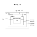
- Fig. 8 shows an image read out one by one from pixels corresponding to the 2.34x angle 744 of view in Fig. 7 in both the horizontal and vertical directions.
- This image corresponds to a mode in which signals are read out pixel by pixel from the third readout angle 603 of view in Fig. 3 in both the horizontal and vertical directions. In other words, signals are read out at a thinning rate of 1/1 in this mode.
- signals may be read out only from a region of the image sensing element 2 that corresponds to the 2.34x angle 744 of view, or from a region widened by several or several ten pixels.
- the added readout pixels can be used for image processing when generating an image of 640 x 480 pixels in the horizontal and vertical directions, which is the pixel count for movie recording.
- a 2.34x angle 751 of view which corresponds to the 2.34x angle 744 of view in Fig. 7 , is obtained by reading out 1,280 x 960 pixels in the horizontal and vertical directions at the 1/1 thinning rate.
- the 1,280 x 960 readout pixels in the horizontal and vertical directions are used to generate an image of 640 x 480 pixels in the horizontal and vertical directions.
- the generated image is equivalent to a 2.34x electronic zoom image.
- a 3.00x angle 752 of view contains 1,000 x 750 pixels in the horizontal and vertical directions out of the 2.34x angle 751 of view obtained by readout at the 1/1 thinning rate.
- the 1,000 x 750 pixels in the horizontal and vertical directions are used to generate an image of 640 x 480 pixels in the horizontal and vertical directions.
- the generated image is equivalent to a 3.00x electronic zoom image.
- a 3.75x angle 753 of view contains 800 x 600 pixels in the horizontal and vertical directions out of the 2.34x angle 751 of view obtained by readout at the 1/1 thinning rate.
- the 800 x 600 pixels in the horizontal and vertical directions are used to generate an image of 640 x 480 pixels in the horizontal and vertical directions.
- the generated image is equivalent to a 3.75x electronic zoom image.
- a 4.69x angle 754 of view contains 640 x 480 pixels in the horizontal and vertical directions out of the 2.34x angle 751 of view obtained by readout at the 1/1 thinning rate.
- An image of 640 x 480 pixels in the horizontal and vertical directions is directly equivalent to a 4.69x electronic zoom image.
- angles 731 to 734 of view, angles 741 to 744 of view, and angles 751 to 754 of view coincide or almost coincide with each other.
- angles 731 to 734 of view, angles 741 to 744 of view, and angles 751 to 754 of view are used to generate images of 640 x 480 pixels in the horizontal and vertical directions for movie recording.
- these angles of view may be expressed as electronic zoom stop positions.
- Image processing by the image sensing apparatus sometimes requires several or several ten filtering pixels outside the recording region when performing pixel interpolation by the R interpolation circuit 91, G interpolation circuit 92, and B interpolation circuit 93, and removal of a false color such as moire by the color signal correction circuit 95.
- the readout angle of view of the image sensing element 2 and the readout angle of view of the electronic zoom may be determined to arrange several or several ten filtering pixels outside the angle of view used in the embodiment.
- control of the electronic zoom starts in response to an instruction from the zoom button or zoom lever of the operation unit 9.
- the synchronous control unit 10 detects which of the high- and low-magnification sides is designated with the zoom button or zoom lever of the operation unit 9. The synchronous control unit 10 decides the next electronic zoom stop position from the current one, and switches driving of the image sensing element 2.
- the image sensing element 2 reads out signals from the 1.00x angle 731 of view serving as the full angle of view in Fig. 6 while thinning them at a thinning rate of 1/3.
- the signal processing unit 5 generates an image of 640 x 480 pixels in the horizontal and vertical directions using the 1,000 x 750 readout pixels in the horizontal and vertical directions. The generated image is displayed or recorded, or displayed and recorded.
- the instruction from the operation unit 9 is to zoom toward the high-magnification side, 800 x 600 pixels in the horizontal and vertical directions in the 1.25x angle 732 of view are used while the 1.00x angle 731 of view serving as the full angle of view in Fig. 6 is kept set for readout from the image sensing element 2.
- the signal processing unit 5 generates an image of 640 x 480 pixels in the horizontal and vertical directions. If the instruction from the operation unit 9 ends, the image generated by continuously reading out signals from the image sensing element 2 is displayed or recorded, or displayed and recorded as a 1.25x electronic zoom image.
- 720 x 540 pixels in the horizontal and vertical directions in the 1.39x angle 733 of view are used while the 1.00x angle 731 of view serving as the full angle of view in Fig. 6 is kept set for readout from the image sensing element 2.
- the signal processing unit 5 generates an image of 640 x 480 pixels in the horizontal and vertical directions. If the instruction from the operation unit 9 ends, the image generated by continuously reading out signals from the image sensing element 2 is displayed or recorded, or displayed and recorded as a 1.39x electronic zoom image.
- the instruction is kept input from the operation unit 9 to zoom toward the high-magnification side, readout from the image sensing element 2 is switched to the angle of view in Fig. 7 , and signals are read out from the 1.56x angle 741 of view while thinning them at a thinning rate of 1/2.
- the signal processing unit 5 generates an image of 640 x 480 pixels in the horizontal and vertical directions using 960 x 720 readout pixels in the horizontal and vertical directions. The generated image is displayed or recorded, or displayed and recorded. If the instruction from the operation unit 9 ends, the image generated by continuously reading out signals from the image sensing element 2 is kept displayed or recorded, or displayed and recorded as a 1.56x electronic zoom image.
- the instruction is kept input from the operation unit 9 to zoom toward the high-magnification side, 800 x 600 pixels in the horizontal and vertical directions in the 1.88x angle 742 of view are used while the 1.56x angle 741 of view in Fig. 7 is kept set for readout from the image sensing element 2.
- the signal processing unit 5 generates an image of 640 x 480 pixels in the horizontal and vertical directions. The generated image is displayed or recorded, or displayed and recorded. If the instruction from the operation unit 9 ends, the image generated by continuously reading out signals from the image sensing element 2 is kept displayed or recorded, or displayed and recorded as a 1.88x electronic zoom image.
- the instruction is kept input from the operation unit 9 to zoom toward the high-magnification side, 700 x 525 pixels in the horizontal and vertical directions in the 2.14x angle 743 of view are used while the 1.56x angle 741 of view in Fig. 7 is kept set for readout from the image sensing element 2.
- the signal processing unit 5 generates an image of 640 x 480 pixels in the horizontal and vertical directions. The generated image is displayed or recorded, or displayed and recorded. If the instruction from the operation unit 9 ends, the image generated by continuously reading out signals from the image sensing element 2 is kept displayed or recorded, or displayed and recorded as a 2.14x electronic zoom image.
- the instruction is kept input from the operation unit 9 to zoom toward the high-magnification side, readout from the image sensing element 2 is switched to the angle of view in Fig. 8 , and signals are read out from the 2.34x angle 751 of view at a thinning rate of 1/1.
- the signal processing unit 5 generates an image of 640 x 480 pixels in the horizontal and vertical directions using 1,280 x 960 readout pixels in the horizontal and vertical directions. The generated image is displayed or recorded, or displayed and recorded. If the instruction from the operation unit 9 ends, the image generated by continuously reading out signals from the image sensing element 2 is kept displayed or recorded, or displayed and recorded as a 2.34x electronic zoom image.
- the instruction is kept input from the operation unit 9 to zoom toward the high-magnification side, 1,000 x 750 pixels in the horizontal and vertical directions in the 3.00x angle 752 of view are used while the 2.34x angle 751 of view in Fig. 8 is kept set for readout from the image sensing element 2.
- the signal processing unit 5 generates an image of 640 x 480 pixels in the horizontal and vertical directions. The generated image is displayed or recorded, or displayed and recorded. If the instruction from the operation unit 9 ends, the image generated by continuously reading out signals from the image sensing element 2 is kept displayed or recorded, or displayed and recorded as a 3.00x electronic zoom image.
- the instruction is kept input from the operation unit 9 to zoom toward the high-magnification side, 800 x 600 pixels in the horizontal and vertical directions in the 3.75x angle 753 of view are used while the 2.34x angle 751 of view in Fig. 8 is kept set for readout from the image sensing element 2.
- the signal processing unit 5 generates an image of 640 x 480 pixels in the horizontal and vertical directions. The generated image is displayed or recorded, or displayed and recorded. If the instruction from the operation unit 9 ends, the image generated by continuously reading out signals from the image sensing element 2 is kept displayed or recorded, or displayed and recorded as a 3.75x electronic zoom image.
- 640 x 480 pixels in the horizontal and vertical directions in the 4.69x angle 754 of view are used while the 2.34x angle 751 of view in Fig. 8 is kept set for readout from the image sensing element 2.
- the signal processing unit 5 generates an image of 640 ⁇ 480 pixels in the horizontal and vertical directions. The generated image is displayed or recorded, or displayed and recorded. If the instruction from the operation unit 9 ends, the image generated by continuously reading out signals from the image sensing element 2 is kept displayed or recorded, or displayed and recorded as a 4.69x electronic zoom image.
- the electronic zoom stop position is assumed to be the 4.69x electronic zoom stop position in Fig. 8 and the operation unit 9 is used to electronically zoom toward the low-magnification side.
- each electronic zoom stop position is the same as that when electronically zooming toward the high-magnification side, and a description thereof will not be repeated.
- the angle of view changes in order from the 4.69x angle 754 of view to the 2.34x angle 751 of view while keeping the mode in which the image sensing element 2 reads out signals from the 2.34x angle 751 of view in Fig. 8 at a thinning rate of 1/1.
- the signal processing unit 5 generates an image of 640 ⁇ 480 pixels in the horizontal and vertical directions based on each electronic zoom magnification. The generated image is displayed or recorded, or displayed and recorded.
- the signal processing unit 5 For the 2.14x to 1.56x electronic zooms, readout from the image sensing element 2 is switched to the angle of view in Fig. 7 .
- the angle of view changes in order from the 2.14x angle 743 of view to the 1.56x angle 741 of view while keeping the mode in which signals are read out from the 1.56x angle 741 of view at a thinning rate of 1/2.
- the signal processing unit 5 generates an image of 640 ⁇ 480 pixels in the horizontal and vertical directions based on each electronic zoom magnification. The generated image is displayed or recorded, or displayed and recorded.
- the signal processing unit 5 For the 1.39x to 1.00x (equal magnification) electronic zooms, readout from the image sensing element 2 is switched to the angle of view in Fig. 6 .
- the angle of view changes in order from the 1.39x angle 733 of view to the 1.00x angle 731 of view while keeping the mode in which signals are read out from the 1.00x angle 731 of view at a thinning rate of 1/3.
- the signal processing unit 5 generates an image of 640 ⁇ 480 pixels in the horizontal and vertical directions based on each electronic zoom magnification. The generated image is displayed or recorded, or displayed and recorded.
- the electronic zoom when the electronic zoom is done from an intermediate electronic zoom stop position toward the high- or low-magnification side, it starts from an intermediate angle of view as described above in accordance with an instruction from the operation unit 9 to electronically zoom toward the high- or low-magnification side. A description of this operation will be omitted.
- a zoom image is always generated using 640 ⁇ 480 or more pixels in the horizontal and vertical directions which are equal to or higher than the pixel count for movie recording.
- An electronic zoom almost free from the degradation of resolution can be provided.
- the pixel count of the 2.34x angle 751 of view serving as the readout angle of view of the image sensing element 2 shown in Fig. 8 is twice as large as the movie recording pixel count of 640 ⁇ 480 pixels in the horizontal and vertical directions.
- the pixel count of the 1.56x angle 741 of view serving as the readout angle of view of the image sensing element 2 shown in Fig. 7 is 1.5 times as large as the movie recording pixel count of 640 ⁇ 480 pixels in the horizontal and vertical directions.
- a pixel count at which signals are read out from a readout angle of view at a thinning rate before switching is (p+1)/p times or more in both the horizontal and vertical directions.
- the ratio between the maximum and minimum readout pixel counts falls within 1/2.
- This setting can prevent the readout time of a shot image from becoming long within the region when the electronic zoom is executed.
- the image quality differs between an image generated from an image having the movie recording pixel count of 640 ⁇ 480 pixels or more in the horizontal and vertical directions without decreasing the pixel count and an image generated from an image having the movie recording pixel count (640 ⁇ 480) while decreasing the pixel count. That is, the resolution after image processing and the quality of a false color such as color noise or moire changes.
- the first embodiment does not utilize modes in which an image is generated from 640 ⁇ 480 pixels in the horizontal and vertical directions, which is the pixel count for movie recording, in the 1.56x angle 734 of view in Fig. 6 and the 2.34x angle 744 of view in Fig. 7 .
- the same image quality can always be maintained.
- the first embodiment does not use modes in which an image is generated from 640 ⁇ 480 pixels in the horizontal and vertical directions, which is the pixel count for movie recording, in the 1.56x angle 734 of view in Fig. 6 and the 2.34x angle 744 of view in Fig. 7 . Hence, these modes may be omitted.
- the readout angle of view of the image sensing element 2 is switched between the 1.39x and 1.56x electronic zooms and between the 2.14x and 2.34x electronic zooms along with an operation to change the electronic zoom magnification.
- driving of the image sensing element 2 is switched between the 1.39x angle 733 of view in Fig. 6 and the 1.56x angle 741 of view in Fig. 7 and between the 2.14x angle 743 of view in Fig. 7 and the 2.34x angle 751 of view in Fig. 8 .
- the synchronous control unit 10 selects either the 1.39x angle 733 of view in Fig. 6 or the 1.56x angle 741 of view in Fig. 7 . If the control has not been completed, the image sensing element 2 is frequently switched between the 1.39x angle 733 of view in Fig. 6 and the 1.56x angle 741 of view in Fig. 7 .
- the synchronous control unit 10 repetitively executes control to simultaneously switch driving control of the image sensing element 2 and operation control of the signal processing unit 5. This places a heavy burden on the synchronous control unit 10, obstructing control of the optical system 1, the memory 6 for storing an image, the image display unit 7, the image recording unit 8, the operation unit 9, and the like.
- control of the electronic zoom starts in response to an instruction from the zoom button or zoom lever of an operation unit 9.
- a synchronous control unit 10 detects which of the high- and low-magnification sides is designated with the zoom button or zoom lever of the operation unit 9. The synchronous control unit 10 decides the next electronic zoom stop position from the current one, and switches driving of the image sensing element 2.
- the image sensing element 2 reads out signals from a 1.00x angle 731 of view serving as the full angle of view in Fig. 6 while thinning them at a thinning rate of 1/3.
- a signal processing unit 5 generates an image of 640 ⁇ 480 pixels in the horizontal and vertical directions using the 1,000 ⁇ 750 readout pixels in the horizontal and vertical directions. The generated image is displayed or recorded, or displayed and recorded.
- the angle of view changes in order from the 1.00x angle 731 of view to a 1.39x angle 733 of view while keeping the mode in which the image sensing element 2 reads out signals from the 1.00x angle 731 of view in Fig. 6 at the 1/3 thinning rate.
- the signal processing unit 5 generates an image of 640 ⁇ 480 pixels in the horizontal and vertical directions based on each electronic zoom magnification. The generated image is displayed or recorded, or displayed and recorded.
- 640 ⁇ 480 pixels in a 1.56x angle 734 of view are used while the 1.00x angle 731 of view serving as the full angle of view in Fig. 6 is kept set for readout from the image sensing element 2.
- the signal processing unit 5 generates an image of 640 ⁇ 480 pixels in the horizontal and vertical directions. The generated image is displayed or recorded, or displayed and recorded. If the instruction from the operation unit 9 ends, the image generated by continuously reading out signals from the image sensing element 2 is kept displayed or recorded, or displayed and recorded as a 1.56x electronic zoom image.
- the angle of view changes in order from a 1.88x angle 742 of view to a 2.14x angle 743 of view while keeping the mode in which signals are read out from a 1.56x angle 741 of view at a thinning rate of 1/2.
- the signal processing unit 5 generates an image of 640 ⁇ 480 pixels in the horizontal and vertical directions based on each electronic zoom magnification. The generated image is displayed or recorded, or displayed and recorded.
- 640 ⁇ 480 pixels in a 2.34x angle 744 of view are used while the 1.56x angle 741 of view in Fig. 7 is kept set for readout from the image sensing element 2.
- the signal processing unit 5 generates an image of 640 ⁇ 480 pixels in the horizontal and vertical directions. The generated image is displayed or recorded, or displayed and recorded. If the instruction from the operation unit 9 ends, the image generated by continuously reading out signals from the image sensing element 2 is kept displayed or recorded, or displayed and recorded as a 2.34x electronic zoom image.
- the angle of view changes in order from a 3.00x angle 752 of view to a 4.69x angle 754 of view while keeping the mode in which signals are read out from a 2.34x angle 751 of view at a thinning rate of 1/1.
- the signal processing unit 5 generates an image of 640 ⁇ 480 pixels in the horizontal and vertical directions based on each electronic zoom magnification. The generated image is displayed or recorded, or displayed and recorded.
- the electronic zoom stop position is assumed to be the 4.69x electronic zoom stop position in Fig. 8 and the operation unit 9 is used to electronically zoom toward the low-magnification side.
- the angle of view changes in order from the 4.69x angle 754 of view to the 2.34x angle 751 of view while keeping the mode in which the image sensing element 2 reads out signals from the 2.34x angle 751 of view in Fig. 8 at a thinning rate of 1/1.
- the signal processing unit 5 generates an image of 640 ⁇ 480 pixels in the horizontal and vertical directions based on each electronic zoom magnification. The generated image is displayed or recorded, or displayed and recorded.
- the signal processing unit 5 For the 2.14x to 1.56x electronic zooms, readout from the image sensing element 2 is switched to the angle of view in Fig. 7 .
- the angle of view changes in order from the 2.14x angle 743 of view to the 1.56x angle 741 of view while keeping the mode in which signals are read out from the 1.56x angle 741 of view at a thinning rate of 1/2.
- the signal processing unit 5 generates an image of 640 ⁇ 480 pixels in the horizontal and vertical directions based on each electronic zoom magnification. The generated image is displayed or recorded, or displayed and recorded.
- the signal processing unit 5 For the 1.39x to 1.00x (equal magnification) electronic zooms, readout from the image sensing element 2 is switched to the angle of view in Fig. 6 .
- the angle of view changes in order from the 1.39x angle 733 of view to the 1.00x angle 731 of view while keeping the mode in which signals are read out from the 1.00x angle 731 of view at a thinning rate of 1/3.
- the signal processing unit 5 generates an image of 640 ⁇ 480 pixels in the horizontal and vertical directions based on each electronic zoom magnification. The generated image is displayed or recorded, or displayed and recorded.
- the electronic zoom when the electronic zoom is done from an intermediate electronic zoom stop position toward the high- or low-magnification side, it starts from an intermediate angle of view as described above in accordance with an instruction from the operation unit 9 to electronically zoom toward the high- or low-magnification side. A description of this operation will be omitted.
- a zoom image is always generated using 640 ⁇ 480 or more pixels in the horizontal and vertical directions which are equal to or higher than the pixel count for movie recording.
- An electronic zoom almost free from the degradation of resolution can be achieved.
- the pixel count of the 2.34x angle 751 of view serving as the readout angle of view of the image sensing element 2 shown in Fig. 8 is twice as large as the movie recording pixel count of 640 ⁇ 480 pixels in the horizontal and vertical directions.
- the pixel count of the 1.56x angle 741 of view serving as the readout angle of view of the image sensing element 2 shown in Fig. 7 is 1.5 times as large as the movie recording pixel count of 640 ⁇ 480 pixels in the horizontal and vertical directions.
- the ratio between the maximum and minimum readout pixel counts falls within 1/2.
- This setting can prevent the readout time of a shot image from becoming long within the region when the electronic zoom is executed.
- the readout angle of view of the image sensing element 2 is switched between the 1.56x and 1.88x electronic zooms and between the 2.34x and 3.00x electronic zooms.
- the readout angle of view of the image sensing element 2 is switched between the 2.34x and 2.14x electronic zooms and between the 1.56x and 1.39x electronic zooms.
- the switching point of the readout angle of view of the image sensing element 2 differs between electronic zooming toward the high-magnification side and that toward the low-magnification side. At any zoom stop position, a change of the angle of view accompanied by switching the readout angle of view of the image sensing element 2 is not frequently repeated. The control rule becomes clear, reducing the burden on the synchronous control unit 10.
- Figs. 1 to 5 The third embodiment will be described below with reference to Figs. 1 to 5 and 9 to 11 .
- the arrangements in Figs. 1 to 5 are the same as those in the first embodiment, and a description thereof will not be repeated.
- the third embodiment executes an electronic zoom operation which does not frequently repeat switching of the readout angle of view of an image sensing element 2 while suppressing the degradation of resolution and image quality.
- the total pixel count of the image sensing element 2 is 3,000 ⁇ 2,250 in the horizontal and vertical directions
- the pixel count for movie recording is VGA-compatible 640 ⁇ 480 in the horizontal and vertical directions.
- Fig. 9 is a view showing an image read out from all the pixels of the image sensing element 2 while thinning them at a thinning rate of 1/3. This image corresponds to a mode in which signals are read out from a first readout angle 601 of view in Fig. 3 at the 1/3 thinning rate in both the horizontal and vertical directions.
- a 1.00x angle 701 of view (full angle of view) is obtained by reading out a total of 3,000 ⁇ 2,250 pixels in the horizontal and vertical directions while thinning them at the 1/3 thinning rate.
- the horizontal readout pixel count is 1,000 and the vertical one is 750.
- the 1,000 ⁇ 750 pixels in the horizontal and vertical directions are used to generate an image of 640 ⁇ 480 pixels in the horizontal and vertical directions.
- the generated image is equivalent to a 1.00x (equal magnification) electronic zoom image.
- a 1.25x angle 702 of view contains 800 ⁇ 600 pixels in the horizontal and vertical directions out of the 1.00x angle 701 of view obtained by thinning readout at the 1/3 thinning rate.
- the 800 ⁇ 600 pixels in the horizontal and vertical directions are used to generate an image of 640 ⁇ 480 pixels in the horizontal and vertical directions.
- the generated image is equivalent to a 1.25x electronic zoom image.
- a pixel count of the image sensing element 2 corresponding to the 1.25x angle 702 of view is 2,400 ⁇ 1,800 in the horizontal and vertical directions.
- a 1.39x angle 703 of view contains 720 ⁇ 540 pixels in the horizontal and vertical directions out of the 1.00x angle 701 of view obtained by thinning readout at the 1/3 thinning rate.
- the 720 ⁇ 540 pixels in the horizontal and vertical directions are used to generate an image of 640 ⁇ 480 pixels in the horizontal and vertical directions.
- the generated image is equivalent to a 1.39x electronic zoom image.
- a pixel count of the image sensing element 2 corresponding to the 1.39x angle 703 of view is 2,160 ⁇ 1,620 in the horizontal and vertical directions.
- a 1.56x angle 704 of view contains 640 ⁇ 480 pixels in the horizontal and vertical directions out of the 1.00x angle 701 of view obtained by thinning readout at the 1/3 thinning rate.
- An image of 640 ⁇ 480 pixels in the horizontal and vertical directions is directly equivalent to a 1.56x electronic zoom image.
- a pixel count of the image sensing element 2 corresponding to the 1.56x angle 704 of view is 1,920 ⁇ 1,440 in the horizontal and vertical directions.
- Fig. 10 shows an image read out from pixels corresponding to the 1.39x angle 703 of view in Fig. 9 while thinning them at a thinning rate of 1/2.
- This image corresponds to a mode in which signals are read out from a second readout angle 602 of view in Fig. 3 at the 1/2 thinning rate in both the horizontal and vertical directions.
- signals may be read out only from a region of the image sensing element 2 that corresponds to the 1.39x angle 703 of view, or from a region widened by several or several ten pixels.
- the added readout pixels can be used for image processing when generating an image of 640 ⁇ 480 pixels in the horizontal and vertical directions, which is the pixel count for movie recording.
- a 1.39x angle 711 of view which corresponds to the 1.39x angle 703 of view in Fig. 9 , is obtained by reading out 2,160 ⁇ 1,620 pixels in the horizontal and vertical directions while thinning them at the 1/2 thinning rate.
- the horizontal readout pixel count is 1,080 and the vertical one is 810.
- the 1,080 ⁇ 810 pixels in the horizontal and vertical directions are used to generate an image of 640 ⁇ 480 pixels in the horizontal and vertical directions.
- the generated image is equivalent to a 1.39x electronic zoom image.
- a 1.56x angle 712 of view contains 960 ⁇ 720 pixels in the horizontal and vertical directions out of the 1.39x angle 711 of view obtained by thinning readout at the 1/2 thinning rate.
- the 960 ⁇ 720 pixels in the horizontal and vertical directions are used to generate an image of 640 ⁇ 480 pixels in the horizontal and vertical directions.
- the generated image is equivalent to a 1.56x electronic zoom image.
- a pixel count of the image sensing element 2 corresponding to the 1.56x angle 712 of view is 1,920 ⁇ 1,440 in the horizontal and vertical directions.
- a 1.88x angle 713 of view contains 800 ⁇ 600 pixels in the horizontal and vertical directions out of the 1.39x angle 711 of view obtained by thinning readout at the 1/2 thinning rate.
- the 800 ⁇ 600 pixels in the horizontal and vertical directions are used to generate an image of 640 ⁇ 480 pixels in the horizontal and vertical directions.
- the generated image is equivalent to a 1.88x electronic zoom image.
- a pixel count of the image sensing element 2 corresponding to the 1.88x angle 713 of view is 1,600 ⁇ 1,200 in the horizontal and vertical directions.
- a 2.14x angle 714 of view contains 700 ⁇ 525 pixels in the horizontal and vertical directions out of the 1.39x angle 711 of view obtained by thinning readout at the 1/2 thinning rate.
- the 700 ⁇ 525 pixels in the horizontal and vertical directions are used to generate an image of 640 ⁇ 480 pixels in the horizontal and vertical directions.
- the generated image is equivalent to a 2.14x electronic zoom image.
- a pixel count of the image sensing element 2 corresponding to the 2.14x angle 714 of view is 1,400 ⁇ 1,050 in the horizontal and vertical directions.
- a 2.34x angle 715 of view contains 640 ⁇ 480 pixels in the horizontal and vertical directions out of the 1.39x angle 711 of view obtained by thinning readout at the 1/2 thinning rate.
- An image of 640 ⁇ 480 pixels in the horizontal and vertical directions is directly equivalent to a 2.34x electronic zoom image.
- a pixel count of the image sensing element 2 corresponding to the 2.34x angle 715 of view is 1,280 ⁇ 960 in the horizontal and vertical directions.
- Fig. 11 shows an image read out one by one from pixels corresponding to the 2.14x angle 714 of view in Fig. 10 in both the horizontal and vertical directions.
- This image corresponds to a mode in which signals are read out pixel by pixel from a third readout angle 603 of view in Fig. 3 in both the horizontal and vertical directions.
- signals are read out at a thinning rate of 1/1 in this mode.
- signals may be read out only from a region of the image sensing element 2 that corresponds to the 2.14x angle 714 of view, or from a region widened by several or several ten pixels.
- the added readout pixels can be used for image processing when generating an image of 640 ⁇ 480 pixels in the horizontal and vertical directions, which is the pixel count for movie recording.
- a 2.14x angle 721 of view which corresponds to the 2.14x angle 714 of view in Fig. 10 , is obtained by reading out 1,400 ⁇ 1,050 pixels in the horizontal and vertical directions at the 1/1 thinning rate.
- the 1,400 ⁇ 1,050 readout pixels in the horizontal and vertical directions are used to generate an image of 640 ⁇ 480 pixels in the horizontal and vertical directions.
- the generated image is equivalent to a 2.14x electronic zoom image.
- a 2.34x angle 722 of view contains 1,280 ⁇ 960 pixels in the horizontal and vertical directions out of the 2.14x angle 721 of view obtained by readout at the 1/1 thinning rate.
- the 1,280 ⁇ 960 pixels in the horizontal and vertical directions are used to generate an image of 640 ⁇ 480 pixels in the horizontal and vertical directions.
- the generated image is equivalent to a 2.34x electronic zoom image.
- a 3.00x angle 723 of view contains 1,000 ⁇ 750 pixels in the horizontal and vertical directions out of the 2.14x angle 721 of view obtained by readout at the 1/1 thinning rate.
- the 1,000 ⁇ 750 pixels in the horizontal and vertical directions are used to generate an image of 640 ⁇ 480 pixels in the horizontal and vertical directions.
- the generated image is equivalent to a 3.00x electronic zoom image.
- a 3.75x angle 724 of view contains 800 ⁇ 600 pixels in the horizontal and vertical directions out of the 2.14x angle 721 of view obtained by readout at the 1/1 thinning rate.
- the 800 ⁇ 600 pixels in the horizontal and vertical directions are used to generate an image of 640 ⁇ 480 pixels in the horizontal and vertical directions.
- the generated image is equivalent to a 3.75x electronic zoom image.
- a 4.69x angle 725 of view contains 640 ⁇ 480 pixels in the horizontal and vertical directions out of the 2.14x angle 721 of view obtained by readout at the 1/1 thinning rate.
- An image of 640 ⁇ 480 pixels in the horizontal and vertical directions is directly equivalent to a 4.69x electronic zoom image.
- angles 701 to 704 of view The centers of the angles 701 to 704 of view, angles 711 to 715 of view, and angles 721 to 725 of view coincide or almost coincide with each other.
- angles 701 to 704 of view, angles 711 to 715 of view, and angles 721 to 725 of view are used to generate images of 640 ⁇ 480 pixels in the horizontal and vertical directions for movie recording.
- these angles of view may be expressed as electronic zoom stop positions.
- Image processing by an image sensing apparatus sometimes requires several or several ten filtering pixels outside the recording region when performing pixel interpolation by an R interpolation circuit 91, G interpolation circuit 92, and B interpolation circuit 93, and removal of a false color such as moire by a color signal correction circuit 95.
- the readout angle of view of the image sensing element 2 and the readout angle of view of the electronic zoom may be determined to arrange several or several ten filtering pixels outside the angle of view used in the embodiment.
- control of the electronic zoom starts in response to an instruction from the zoom button or zoom lever of an operation unit 9.
- a synchronous control unit 10 detects which of the high- and low-magnification sides is designated with the zoom button or zoom lever of the operation unit 9. The synchronous control unit 10 decides the next electronic zoom stop position from the current one, and switches driving of the image sensing element 2.
- the image sensing element 2 reads out signals from the 1.00x angle 701 of view serving as the full angle of view in Fig. 9 while thinning them at a thinning rate of 1/3.
- a signal processing unit 5 generates an image of 640 ⁇ 480 pixels in the horizontal and vertical directions using the 1,000 ⁇ 750 readout pixels in the horizontal and vertical directions. The generated image is displayed or recorded, or displayed and recorded.
- the instruction from the operation unit 9 is to zoom toward the high-magnification side, 800 ⁇ 600 pixels in the horizontal and vertical directions in the 1.25x angle 702 of view are used while the 1.00x angle 701 of view serving as the full angle of view in Fig. 9 is kept set for readout from the image sensing element 2.
- the signal processing unit 5 generates an image of 640 ⁇ 480 pixels in the horizontal and vertical directions. If the instruction from the operation unit 9 ends, the image generated by continuously reading out signals from the image sensing element 2 is displayed or recorded, or displayed and recorded as a 1.25x electronic zoom image.
- the instruction is kept input from the operation unit 9 to zoom toward the high-magnification side, 720 ⁇ 540 pixels in the horizontal and vertical directions in the 1.39x angle 703 of view are used while the 1.00x angle 701 of view serving as the full angle of view in Fig. 9 is kept set for readout from the image sensing element 2.
- the signal processing unit 5 generates an image of 640 ⁇ 480 pixels in the horizontal and vertical directions. If the instruction from the operation unit 9 ends, the image generated by continuously reading out signals from the image sensing element 2 is displayed or recorded, or displayed and recorded as a 1.39x electronic zoom image.
- the instruction is kept input from the operation unit 9 to zoom toward the high-magnification side, readout from the image sensing element 2 is switched to the angle of view in Fig. 10 , and signals are read out from the 1.39x angle 711 of view while thinning them at a thinning rate of 1/2.
- the signal processing unit 5 generates an image of 640 ⁇ 480 pixels in the horizontal and vertical directions using 960 ⁇ 720 pixels in the horizontal and vertical directions, which correspond to the 1.56x angle 712 of view, out of the 1,080 ⁇ 810 readout pixels in the horizontal and vertical directions.
- the generated image is displayed or recorded, or displayed and recorded. If the instruction from the operation unit 9 ends, the image generated by continuously reading out signals from the image sensing element 2 is kept displayed or recorded, or displayed and recorded as a 1.56x electronic zoom image.
- the instruction is kept input from the operation unit 9 to zoom toward the high-magnification side, 800 ⁇ 600 pixels in the horizontal and vertical directions in the 1.88x angle 713 of view are used while the 1.39x angle 711 of view in Fig. 10 is kept set for readout from the image sensing element 2.
- the signal processing unit 5 generates an image of 640 ⁇ 480 pixels in the horizontal and vertical directions. The generated image is displayed or recorded, or displayed and recorded. If the instruction from the operation unit 9 ends, the image generated by continuously reading out signals from the image sensing element 2 is kept displayed or recorded, or displayed and recorded as a 1.88x electronic zoom image.
- the instruction is kept input from the operation unit 9 to zoom toward the high-magnification side, 700 ⁇ 525 pixels in the horizontal and vertical directions in the 2.14x angle 714 of view are used while the 1.39x angle 711 of view in Fig. 10 is kept set for readout from the image sensing element 2.
- the signal processing unit 5 generates an image of 640 ⁇ 480 pixels in the horizontal and vertical directions. The generated image is displayed or recorded, or displayed and recorded. If the instruction from the operation unit 9 ends, the image generated by continuously reading out signals from the image sensing element 2 is kept displayed or recorded, or displayed and recorded as a 2.14x electronic zoom image.
- the instruction is kept input from the operation unit 9 to zoom toward the high-magnification side, readout from the image sensing element 2 is switched to the angle of view in Fig. 11 , and signals are read out from the 2.14x angle 721 of view at a thinning rate of 1/1.
- the signal processing unit 5 generates an image of 640 ⁇ 480 pixels in the horizontal and vertical directions using 1,280 ⁇ 960 pixels in the horizontal and vertical directions, which correspond to the 2.34x angle 722 of view, out of the 1,400 ⁇ 1,050 readout pixels in the horizontal and vertical directions.
- the generated image is displayed or recorded, or displayed and recorded. If the instruction from the operation unit 9 ends, the image generated by continuously reading out signals from the image sensing element 2 is kept displayed or recorded, or displayed and recorded as a 2.34x electronic zoom image.
- the instruction is kept input from the operation unit 9 to zoom toward the high-magnification side, 1,000 ⁇ 750 pixels in the horizontal and vertical directions in the 3.00x angle 723 of view are used while the 2.14x angle 721 of view in Fig. 11 is kept set for readout from the image sensing element 2.
- the signal processing unit 5 generates an image of 640 ⁇ 480 pixels in the horizontal and vertical directions. The generated image is displayed or recorded, or displayed and recorded. If the instruction from the operation unit 9 ends, the image generated by continuously reading out signals from the image sensing element 2 is kept displayed or recorded, or displayed and recorded as a 3.00x electronic zoom image.
- the instruction is kept input from the operation unit 9 to zoom toward the high-magnification side, 800 ⁇ 600 pixels in the horizontal and vertical directions in the 3.75x angle 724 of view are used while the 2.14x angle 721 of view in Fig. 11 is kept set for readout from the image sensing element 2.
- the signal processing unit 5 generates an image of 640 ⁇ 480 pixels in the horizontal and vertical directions. The generated image is displayed or recorded, or displayed and recorded. If the instruction from the operation unit 9 ends, the image generated by continuously reading out signals from the image sensing element 2 is kept displayed or recorded, or displayed and recorded as a 3.75x electronic zoom image.
- 640 ⁇ 480 pixels in the horizontal and vertical directions in the 4.69x angle 725 of view are used while the 2.14x angle 721 of view in Fig. 11 is kept set for readout from the image sensing element 2.
- the signal processing unit 5 generates an image of 640 ⁇ 480 pixels in the horizontal and vertical directions. The generated image is displayed or recorded, or displayed and recorded. If the instruction from the operation unit 9 ends, the image generated by continuously reading out signals from the image sensing element 2 is kept displayed or recorded, or displayed and recorded as a 4.69x electronic zoom image.
- the electronic zoom stop position is assumed to be the 4.69x electronic zoom stop position in Fig. 11 and the operation unit 9 is used to electronically zoom toward the low-magnification side.
- each electronic zoom stop position is the same as that when electronically zooming toward the high-magnification side, and a description thereof will not be repeated.
- the angle of view changes in order from the 4.69x angle 725 of view to the 2.34x angle 722 of view while keeping the mode in which the image sensing element 2 reads out signals from the 2.14x angle 721 of view in Fig. 11 at a thinning rate of 1/1.
- the signal processing unit 5 generates an image of 640 ⁇ 480 pixels in the horizontal and vertical directions based on each electronic zoom magnification. The generated image is displayed or recorded, or displayed and recorded.
- the readout from the image sensing element 2 uses 1,400 ⁇ 1,050 pixels in the horizontal and vertical directions read out from the 2.14x angle 721 of view in Fig. 11 at the thinning rate of 1/1.
- the signal processing unit 5 generates an image of 640 ⁇ 480 pixels in the horizontal and vertical directions. The generated image is displayed or recorded, or displayed and recorded. If the instruction from the operation unit 9 ends, the image generated by continuously reading out signals from the image sensing element 2 is kept displayed or recorded, or displayed and recorded as a 2.14x electronic zoom image.
- the signal processing unit 5 For the 1.88x to 1.56x electronic zooms, readout from the image sensing element 2 is switched to the angle of view in Fig. 10 .
- the angle of view changes in order from the 1.88x angle 713 of view to the 1.56x angle 712 of view while keeping the mode in which signals are read out from the 1.39x angle 711 of view at a thinning rate of 1/2.
- the signal processing unit 5 generates an image of 640 ⁇ 480 pixels in the horizontal and vertical directions based on each electronic zoom magnification. The generated image is displayed or recorded, or displayed and recorded.
- the readout from the image sensing element 2 uses 1,080 ⁇ 810 pixels in the horizontal and vertical directions read out from the 1.39x angle 711 of view in Fig. 10 at the thinning rate of 1/2.
- the signal processing unit 5 generates an image of 640 ⁇ 480 pixels in the horizontal and vertical directions. The generated image is displayed or recorded, or displayed and recorded. If the instruction from the operation unit 9 ends, the image generated by continuously reading out signals from the image sensing element 2 is kept displayed or recorded, or displayed and recorded as a 1.39x electronic zoom image.
- the signal processing unit 5 For the 1.25x to 1.00x (equal magnification) electronic zooms, readout from the image sensing element 2 is switched to the angle of view in Fig. 9 .
- the angle of view changes in order from the 1.25x angle 702 of view to the 1.00x angle 701 of view while keeping the mode in which signals are read out from the 1.00x angle 701 of view at a thinning rate of 1/3.
- the signal processing unit 5 generates an image of 640 ⁇ 480 pixels in the horizontal and vertical directions based on each electronic zoom magnification. The generated image is displayed or recorded, or displayed and recorded.
- the electronic zoom when the electronic zoom is done from an intermediate electronic zoom stop position toward the high- or low-magnification side, it starts from an intermediate angle of view as described above in accordance with an instruction from the operation unit 9 to electronically zoom toward the high- or low-magnification side. A description of this operation will be omitted.
- a zoom image is always generated using 640 ⁇ 480 or more pixels in the horizontal and vertical directions which are equal to or higher than the pixel count for movie recording.
- An electronic zoom almost free from the degradation of resolution can be provided.
- the 2.14x angle 721 of view serving as the readout angle of view of the image sensing element 2 shown in Fig. 11 is larger in pixel count by one step than the 2.34x angle 722 of view having a pixel count twice as large as the movie recording pixel count of 640 ⁇ 480 pixels in the horizontal and vertical directions.
- the 1.39x angle 711 of view serving as the readout angle of view of the image sensing element 2 shown in Fig. 10 is larger in pixel count by one step than the 1.56x angle 712 of view having a pixel count 1.5 times as large as the movie recording pixel count of 640 ⁇ 480 pixels in the horizontal and vertical directions.
- the ratio between the maximum and minimum readout pixel counts falls within 1/2.
- This setting can prevent the readout time of a shot image from becoming long within the region when the electronic zoom is executed.
- the image quality differs between an image generated from an image having the movie recording pixel count without decreasing the pixel count and an image generated from an image having the movie recording pixel count while decreasing the pixel count.
- the third embodiment does not utilize modes in which an image is generated from 640 ⁇ 480 pixels in the horizontal and vertical directions, which is the pixel count for movie recording, in the 1.56x angle 704 of view in Fig. 9 and the 2.34x angle 715 of view in Fig. 10 .
- the same image quality can always be maintained.
- the third embodiment does not use modes in which an image is generated from 640 ⁇ 480 pixels in the horizontal and vertical directions, which is the pixel count for movie recording, in the 1.56x angle 704 of view in Fig. 9 and the 2.34x angle 715 of view in Fig. 10 . Hence, these modes may be omitted.
- the readout angle of view of the image sensing element 2 is switched between the 1.39x and 1.56x electronic zooms and between the 2.14x and 2.34x electronic zooms.
- the readout angle of view of the image sensing element 2 is switched between the 2.14x and 1.88x electronic zooms and between the 1.39x and 1.25x electronic zooms.
- the switching point of the readout angle of view of the image sensing element 2 differs between electronic zooming toward the high-magnification side and that toward the low-magnification side. At any zoom stop position, a change of the angle of view accompanied by switching the readout angle of view of the image sensing element 2 is not frequently repeated. The control rule becomes clear, reducing the burden on the synchronous control unit 10.
- the fourth embodiment will be described below with reference to Figs. 1 to 5 and 9 to 11 .
- the arrangements in Figs. 1 to 5 are the same as those in the first embodiment, and a description thereof will not be repeated.
- the operations at respective electronic zoom stop positions in Figs. 9 to 11 are also the same as those in the third embodiment, and a description thereof will not be repeated.
- the readout angle of view of the image sensing element 2 is switched between the 1.39x and 1.56x electronic zooms and between the 2.14x and 2.34x electronic zooms along with an operation to change the electronic zoom magnification.
- driving of the image sensing element 2 is switched between the 1.39x angle 703 of view in Fig. 9 and the 1.56x angle 712 of view in Fig. 10 and between the 2.14x angle 714 of view in Fig. 10 and the 2.34x angle 722 of view in Fig. 11 .
- the synchronous control unit 10 selects either the 1.39x angle 703 of view in Fig. 9 or the 1.56x angle 712 of view in Fig. 10 . If the control has not been completed, the image sensing element 2 is frequently switched between the 1.39x angle 703 of view in Fig. 9 and the 1.56x angle 712 of view in Fig. 10 .
- the synchronous control unit 10 repetitively executes control to simultaneously switch driving control of the image sensing element 2 and operation control of the signal processing unit 5. This places a heavy burden on the synchronous control unit 10, obstructing control of the optical system 1, the memory 6 for storing an image, the image display unit 7, the image recording unit 8, the operation unit 9, and the like.
- the fourth embodiment executes an electronic zoom operation which does not frequently repeat switching of the readout angle of view of an image sensing element 2.
- control of the electronic zoom starts in response to an instruction from the zoom button or zoom lever of an operation unit 9.
- a synchronous control unit 10 detects which of the high- and low-magnification sides is designated with the zoom button or zoom lever of the operation unit 9. The synchronous control unit 10 decides the next electronic zoom stop position from the current one, and switches driving of the image sensing element 2.
- the image sensing element 2 reads out signals from a 1.00x angle 701 of view serving as the full angle of view in Fig. 9 while thinning them at a thinning rate of 1/3.
- a signal processing unit 5 generates an image of 640 ⁇ 480 pixels in the horizontal and vertical directions using the 1,000 ⁇ 750 readout pixels in the horizontal and vertical directions. The generated image is displayed or recorded, or displayed and recorded.
- the angle of view changes in order from the 1.00x angle 701 of view to a 1.39x angle 703 of view while keeping the mode in which the image sensing element 2 reads out signals from the 1.00x angle 701 of view in Fig. 9 at the 1/3 thinning rate.
- the signal processing unit 5 generates an image of 640 ⁇ 480 pixels in the horizontal and vertical directions based on each electronic zoom magnification. The generated image is displayed or recorded, or displayed and recorded.
- 640 ⁇ 480 pixels in a 1.56x angle 704 of view are used while the 1.00x angle 701 of view serving as the full angle of view in Fig. 9 is kept set for readout from the image sensing element 2.
- the signal processing unit 5 generates an image of 640 ⁇ 480 pixels in the horizontal and vertical directions. The generated image is displayed or recorded, or displayed and recorded. If the instruction from the operation unit 9 ends, the image generated by continuously reading out signals from the image sensing element 2 is kept displayed or recorded, or displayed and recorded as a 1.56x electronic zoom image.
- the angle of view changes in order from a 1.88x angle 713 of view to a 2.14x angle 714 of view while keeping the mode in which signals are read out from a 1.39x angle 711 of view at a thinning rate of 1/2.
- the signal processing unit 5 generates an image of 640 ⁇ 480 pixels in the horizontal and vertical directions based on each electronic zoom magnification. The generated image is displayed or recorded, or displayed and recorded.
- 640 ⁇ 480 pixels in a 2.34x angle 715 of view are used while the 1.39x angle 711 of view in Fig. 10 is kept set for readout from the image sensing element 2.
- the signal processing unit 5 generates an image of 640 ⁇ 480 pixels in the horizontal and vertical directions. The generated image is displayed or recorded, or displayed and recorded. If the instruction from the operation unit 9 ends, the image generated by continuously reading out signals from the image sensing element 2 is kept displayed or recorded, or displayed and recorded as a 2.34x electronic zoom image.
- the angle of view changes in order from a 3.00x angle 723 of view to a 4.69x angle 725 of view while keeping the mode in which signals are read out from the 2.14x angle 714 of view at a thinning rate of 1/1.
- the signal processing unit 5 generates an image of 640 ⁇ 480 pixels in the horizontal and vertical directions based on each electronic zoom magnification. The generated image is displayed or recorded, or displayed and recorded.
- the electronic zoom stop position is assumed to be the 4.69x electronic zoom stop position in Fig. 11 and the operation unit 9 is used to electronically zoom toward the low-magnification side.
- the angle of view changes in order from the 4.69x angle 725 of view to a 2.14x angle 721 of view while keeping the mode in which the image sensing element 2 reads out signals from the 2.14x angle 721 of view in Fig. 11 at a thinning rate of 1/1.
- the signal processing unit 5 generates an image of 640 ⁇ 480 pixels in the horizontal and vertical directions based on each electronic zoom magnification. The generated image is displayed or recorded, or displayed and recorded.
- the angle of view changes in order from the 1.88x angle 713 of view to the 1.39x angle 711 of view while keeping the mode in which signals are read out from the 1.39x angle 711 of view at a thinning rate of 1/2.
- the signal processing unit 5 generates an image of 640 ⁇ 480 pixels in the horizontal and vertical directions based on each electronic zoom magnification. The generated image is displayed or recorded, or displayed and recorded.
- the angle of view changes in order from a 1.25x angle 702 of view to the 1.00x angle 701 of view while keeping the mode in which signals are read out from the 1.00x angle 701 of view at a thinning rate of 1/3.
- the signal processing unit 5 generates an image of 640 ⁇ 480 pixels in the horizontal and vertical directions based on each electronic zoom magnification. The generated image is displayed or recorded, or displayed and recorded.
- the electronic zoom when the electronic zoom is done from an intermediate electronic zoom stop position toward the high- or low-magnification side, it starts from an intermediate angle of view as described above in accordance with an instruction from the operation unit 9 to electronically zoom toward the high- or low-magnification side. A description of this operation will be omitted.
- a zoom image is always generated using 640 ⁇ 480 or more pixels in the horizontal and vertical directions which are equal to or higher than the pixel count for movie recording.
- An electronic zoom almost free from the degradation of resolution can be achieved.
- the 2.14x angle 721 of view serving as the readout angle of view of the image sensing element 2 shown in Fig. 11 is larger in pixel count by one step than the 2.34x angle 722 of view having a pixel count twice as large as the movie recording pixel count of 640 ⁇ 480 pixels in the horizontal and vertical directions.
- the 1.39x angle 711 of view serving as the readout angle of view of the image sensing element 2 shown in Fig. 10 is larger in pixel count by one step than the 1.56x angle 712 of view having a pixel count 1.5 times as large as the movie recording pixel count of 640 ⁇ 480 pixels in the horizontal and vertical directions.
- the ratio between the maximum and minimum readout pixel counts falls within 1/2.
- This setting can prevent the readout time of a shot image from becoming long within the region when the electronic zoom is executed.
- the readout angle of view of the image sensing element 2 is switched between the 1.56x and 1.88x electronic zooms and between the 2.34x and 3.00x electronic zooms.
- the readout angle of view of the image sensing element 2 is switched between the 2.14x and 1.88x electronic zooms and between the 1.39x and 1.25x electronic zooms.
- the switching point of the readout angle of view of the image sensing element 2 differs between electronic zooming toward the high-magnification side and that toward the low-magnification side. At any zoom stop position, a change of the angle of view accompanied by switching the readout angle of view of the image sensing element 2 is not frequently repeated. The control rule becomes clear, reducing the burden on the synchronous control unit 10.
- the readout angle of view of the image sensing element 2 may be switched frequently.
- the fourth embodiment controls to switch by a shift of two points a zoom stop position serving as a switching point of the readout angle of view of the image sensing element 2. Even when electronic zooming toward the high-magnification side and that toward the low-magnification side are repetitively executed, the probability at which the readout angle of view of the image sensing element 2 is switched can be decreased, reducing the burden on the synchronous control unit 10.
- the 2.14x angle 721 of view in Fig. 11 is larger by one step than the 2.34x angle 722 of view having a pixel count twice as large as the movie recording pixel count in the horizontal and vertical directions.
- the 1.39x angle 711 of view in Fig. 10 is larger by one step than the 1.56x angle 712 of view having a pixel count 1.5 times as large as the movie recording pixel count in the horizontal and vertical directions.
- the readout angle of view of the image sensing element 2 shown in Fig. 11 may be changed to an angle of view corresponding to the 1.88x angle 713 of view larger by one more step.
- the readout angle of view of the image sensing element 2 shown in Fig. 10 may be changed to an angle of view corresponding to the 1.25x angle 702 of view larger by one more step.
- the maximum readout angle of view of the image sensing element 2 suffices to be determined in consideration of the trade-off between the ease of control of the electronic zoom, and the frame rate in shooting, the limitation on the readout pixel count, or the like.
- aspects of the present invention can also be realized by a computer of a system or apparatus (or devices such as a CPU or MPU) that reads out and executes a program recorded on a memory device to perform the functions of the above-described embodiment(s), and by a method, the steps of which are performed by a computer of a system or apparatus by, for example, reading out and executing a program recorded on a memory device to perform the functions of the above-described embodiment(s).
- the program is provided to the computer for example via a network or from a recording medium of various types serving as the memory device (e.g., computer-readable medium).
Landscapes
- Engineering & Computer Science (AREA)
- Physics & Mathematics (AREA)
- General Physics & Mathematics (AREA)
- Theoretical Computer Science (AREA)
- Multimedia (AREA)
- Signal Processing (AREA)
- Studio Devices (AREA)
- Transforming Light Signals Into Electric Signals (AREA)
Applications Claiming Priority (2)
| Application Number | Priority Date | Filing Date | Title |
|---|---|---|---|
| JP2008223916A JP5284013B2 (ja) | 2008-09-01 | 2008-09-01 | 撮像装置およびその制御方法、プログラム |
| EP09169183A EP2159751A1 (de) | 2008-09-01 | 2009-09-01 | Bildabtastvorrichtung, Steuerungsverfahren und zugehöriges Programm |
Related Parent Applications (1)
| Application Number | Title | Priority Date | Filing Date |
|---|---|---|---|
| EP09169183.2 Division | 2009-09-01 |
Publications (1)
| Publication Number | Publication Date |
|---|---|
| EP2562714A1 true EP2562714A1 (de) | 2013-02-27 |
Family
ID=41258502
Family Applications (2)
| Application Number | Title | Priority Date | Filing Date |
|---|---|---|---|
| EP09169183A Withdrawn EP2159751A1 (de) | 2008-09-01 | 2009-09-01 | Bildabtastvorrichtung, Steuerungsverfahren und zugehöriges Programm |
| EP12187482A Withdrawn EP2562714A1 (de) | 2008-09-01 | 2009-09-01 | Bildabtastvorrichtung, Steuerverfahren und zugehöriges Programm |
Family Applications Before (1)
| Application Number | Title | Priority Date | Filing Date |
|---|---|---|---|
| EP09169183A Withdrawn EP2159751A1 (de) | 2008-09-01 | 2009-09-01 | Bildabtastvorrichtung, Steuerungsverfahren und zugehöriges Programm |
Country Status (4)
| Country | Link |
|---|---|
| US (2) | US8687093B2 (de) |
| EP (2) | EP2159751A1 (de) |
| JP (1) | JP5284013B2 (de) |
| CN (2) | CN101668121A (de) |
Families Citing this family (9)
| Publication number | Priority date | Publication date | Assignee | Title |
|---|---|---|---|---|
| JP5284013B2 (ja) | 2008-09-01 | 2013-09-11 | キヤノン株式会社 | 撮像装置およびその制御方法、プログラム |
| JP5658451B2 (ja) * | 2009-11-30 | 2015-01-28 | ソニー株式会社 | 情報処理装置、情報処理方法及びそのプログラム |
| US20120002084A1 (en) * | 2010-06-30 | 2012-01-05 | True Vision Systems, Inc. | Systems, apparatus, and methods for digital image capture with variable density display and high resolution electronic zoom |
| JP5931619B2 (ja) * | 2012-07-17 | 2016-06-08 | オリンパス株式会社 | 撮像装置 |
| JP6389342B2 (ja) * | 2015-11-17 | 2018-09-12 | 富士フイルム株式会社 | 撮影装置及びその制御方法 |
| JP7324866B2 (ja) * | 2019-12-19 | 2023-08-10 | 富士フイルム株式会社 | 撮像装置 |
| CN113132614B (zh) * | 2019-12-31 | 2023-09-01 | 中兴通讯股份有限公司 | 一种摄像头光学变焦电子装置、方法、单元及存储器 |
| CN112333381B (zh) * | 2020-03-20 | 2022-04-29 | 华为技术有限公司 | 一种控制方法、音圈马达、镜头模组和电子设备 |
| CN111970438B (zh) * | 2020-08-03 | 2022-06-28 | Oppo广东移动通信有限公司 | 变焦处理方法及装置、设备、存储介质 |
Citations (8)
| Publication number | Priority date | Publication date | Assignee | Title |
|---|---|---|---|---|
| EP0916918A2 (de) | 1997-11-12 | 1999-05-19 | Modine Manufacturing Company | Wärmespeicher |
| JP2000295530A (ja) | 1999-04-07 | 2000-10-20 | Canon Inc | 固体撮像装置 |
| JP2002330329A (ja) | 2001-04-27 | 2002-11-15 | Olympus Optical Co Ltd | 撮像装置 |
| US6876386B1 (en) * | 1999-07-30 | 2005-04-05 | Fuji Photo Film Co., Ltd. | Digital camera with downsampling and zoom processing and method of controlling operation of same |
| JP2005191867A (ja) | 2003-12-25 | 2005-07-14 | Olympus Corp | 撮像装置及び電子ズーミング方法 |
| US7257278B2 (en) * | 2003-02-26 | 2007-08-14 | Hewlett-Packard Development Company, L.P. | Image sensor for capturing and filtering image data |
| US20070188632A1 (en) * | 2006-02-14 | 2007-08-16 | Taro Kobayashi | Image capturing apparatus, control method therefor, program, and storage medium |
| EP2159751A1 (de) | 2008-09-01 | 2010-03-03 | Canon Kabushiki Kaisha | Bildabtastvorrichtung, Steuerungsverfahren und zugehöriges Programm |
Family Cites Families (4)
| Publication number | Priority date | Publication date | Assignee | Title |
|---|---|---|---|---|
| JP4624065B2 (ja) * | 2004-10-13 | 2011-02-02 | オリンパス株式会社 | 撮像装置 |
| JP4678849B2 (ja) | 2005-10-31 | 2011-04-27 | キヤノン株式会社 | 撮像装置及びその制御方法及びプログラム及び記憶媒体 |
| JP4655991B2 (ja) * | 2006-04-21 | 2011-03-23 | カシオ計算機株式会社 | 撮像装置及び電子ズーム方法と、プログラム |
| JP4262263B2 (ja) | 2006-06-07 | 2009-05-13 | キヤノン株式会社 | 撮像装置及びその制御方法 |
-
2008
- 2008-09-01 JP JP2008223916A patent/JP5284013B2/ja not_active Expired - Fee Related
-
2009
- 2009-08-21 US US12/545,805 patent/US8687093B2/en not_active Expired - Fee Related
- 2009-08-27 CN CN200910167262.6A patent/CN101668121A/zh active Pending
- 2009-08-27 CN CN2012103567772A patent/CN102883105A/zh active Pending
- 2009-09-01 EP EP09169183A patent/EP2159751A1/de not_active Withdrawn
- 2009-09-01 EP EP12187482A patent/EP2562714A1/de not_active Withdrawn
-
2014
- 2014-02-04 US US14/172,768 patent/US8964068B2/en not_active Expired - Fee Related
Patent Citations (8)
| Publication number | Priority date | Publication date | Assignee | Title |
|---|---|---|---|---|
| EP0916918A2 (de) | 1997-11-12 | 1999-05-19 | Modine Manufacturing Company | Wärmespeicher |
| JP2000295530A (ja) | 1999-04-07 | 2000-10-20 | Canon Inc | 固体撮像装置 |
| US6876386B1 (en) * | 1999-07-30 | 2005-04-05 | Fuji Photo Film Co., Ltd. | Digital camera with downsampling and zoom processing and method of controlling operation of same |
| JP2002330329A (ja) | 2001-04-27 | 2002-11-15 | Olympus Optical Co Ltd | 撮像装置 |
| US7257278B2 (en) * | 2003-02-26 | 2007-08-14 | Hewlett-Packard Development Company, L.P. | Image sensor for capturing and filtering image data |
| JP2005191867A (ja) | 2003-12-25 | 2005-07-14 | Olympus Corp | 撮像装置及び電子ズーミング方法 |
| US20070188632A1 (en) * | 2006-02-14 | 2007-08-16 | Taro Kobayashi | Image capturing apparatus, control method therefor, program, and storage medium |
| EP2159751A1 (de) | 2008-09-01 | 2010-03-03 | Canon Kabushiki Kaisha | Bildabtastvorrichtung, Steuerungsverfahren und zugehöriges Programm |
Also Published As
| Publication number | Publication date |
|---|---|
| CN101668121A (zh) | 2010-03-10 |
| JP2010062671A (ja) | 2010-03-18 |
| US8687093B2 (en) | 2014-04-01 |
| JP5284013B2 (ja) | 2013-09-11 |
| US8964068B2 (en) | 2015-02-24 |
| US20140184855A1 (en) | 2014-07-03 |
| US20100053377A1 (en) | 2010-03-04 |
| CN102883105A (zh) | 2013-01-16 |
| EP2159751A1 (de) | 2010-03-03 |
Similar Documents
| Publication | Publication Date | Title |
|---|---|---|
| US8964068B2 (en) | Image sensing apparatus, control method thereof, and storage medium | |
| US11206353B2 (en) | Electronic apparatus, method for controlling electronic apparatus, and control program for setting image-capture conditions of image sensor | |
| US10638058B2 (en) | Imaging device, imaging method and storage medium | |
| JP4503878B2 (ja) | 撮像装置及び撮像方法 | |
| US7679657B2 (en) | Image sensing apparatus having electronic zoom function, and control method therefor | |
| CN101285989B (zh) | 自动对焦装置、图像拾取装置和自动对焦方法 | |
| US9241109B2 (en) | Image capturing apparatus, control method, and recording medium for moving image generation | |
| JP5314736B2 (ja) | 表示装置 | |
| US9148572B2 (en) | Timing generator, imaging device, and dot-clock output method | |
| JP2010268388A (ja) | 撮像装置 | |
| US8427554B2 (en) | Imaging apparatus and control method therefor | |
| US20170295286A1 (en) | Imaging device, imaging system, and imaging method | |
| JP2005012423A (ja) | 撮像装置及び信号処理装置 | |
| JP5397048B2 (ja) | デジタルカメラ、及びその撮影感度設定方法とプログラム | |
| JP2006261929A (ja) | 撮像装置 | |
| JP2014202879A (ja) | 撮影装置 | |
| JP3516071B2 (ja) | 撮像装置 | |
| JP4266807B2 (ja) | 撮像装置及び電子ズーミング方法 | |
| JP2023077932A (ja) | 電子機器及びその制御方法 | |
| JP4933205B2 (ja) | 撮像装置、およびそれに用いる固体撮像素子、ならびに画像生成方法 | |
| US20260006342A1 (en) | Electronic device and long-exposure video generation method thereof | |
| JP4362094B2 (ja) | 合焦制御装置及び合焦制御方法 | |
| JP5039475B2 (ja) | 固体撮像素子の駆動方法および撮像装置 | |
| JP2022120682A (ja) | 撮像装置及びその制御方法 | |
| JP2007006103A (ja) | 撮影装置 |
Legal Events
| Date | Code | Title | Description |
|---|---|---|---|
| PUAI | Public reference made under article 153(3) epc to a published international application that has entered the european phase |
Free format text: ORIGINAL CODE: 0009012 |
|
| AC | Divisional application: reference to earlier application |
Ref document number: 2159751 Country of ref document: EP Kind code of ref document: P |
|
| AK | Designated contracting states |
Kind code of ref document: A1 Designated state(s): AT BE BG CH CY CZ DE DK EE ES FI FR GB GR HR HU IE IS IT LI LT LU LV MC MK MT NL NO PL PT RO SE SI SK SM TR |
|
| 17P | Request for examination filed |
Effective date: 20130827 |
|
| RBV | Designated contracting states (corrected) |
Designated state(s): AT BE BG CH CY CZ DE DK EE ES FI FR GB GR HR HU IE IS IT LI LT LU LV MC MK MT NL NO PL PT RO SE SI SK SM TR |
|
| 17Q | First examination report despatched |
Effective date: 20131009 |
|
| STAA | Information on the status of an ep patent application or granted ep patent |
Free format text: STATUS: THE APPLICATION HAS BEEN WITHDRAWN |
|
| 18W | Application withdrawn |
Effective date: 20150915 |