EP2562878A2 - Borne de connexion destinée au raccordement électrique de conducteurs - Google Patents
Borne de connexion destinée au raccordement électrique de conducteurs Download PDFInfo
- Publication number
- EP2562878A2 EP2562878A2 EP12178498A EP12178498A EP2562878A2 EP 2562878 A2 EP2562878 A2 EP 2562878A2 EP 12178498 A EP12178498 A EP 12178498A EP 12178498 A EP12178498 A EP 12178498A EP 2562878 A2 EP2562878 A2 EP 2562878A2
- Authority
- EP
- European Patent Office
- Prior art keywords
- contact
- terminal
- transmission element
- clamping device
- actuating
- Prior art date
- Legal status (The legal status is an assumption and is not a legal conclusion. Google has not performed a legal analysis and makes no representation as to the accuracy of the status listed.)
- Withdrawn
Links
- 239000004020 conductor Substances 0.000 title claims description 49
- 230000005540 biological transmission Effects 0.000 claims abstract description 68
- 238000003780 insertion Methods 0.000 claims description 32
- 230000037431 insertion Effects 0.000 claims description 32
- 239000007787 solid Substances 0.000 claims description 8
- 239000007769 metal material Substances 0.000 claims description 4
- 230000006978 adaptation Effects 0.000 description 1
- 238000010276 construction Methods 0.000 description 1
Images


Classifications
-
- H—ELECTRICITY
- H01—ELECTRIC ELEMENTS
- H01R—ELECTRICALLY-CONDUCTIVE CONNECTIONS; STRUCTURAL ASSOCIATIONS OF A PLURALITY OF MUTUALLY-INSULATED ELECTRICAL CONNECTING ELEMENTS; COUPLING DEVICES; CURRENT COLLECTORS
- H01R4/00—Electrically-conductive connections between two or more conductive members in direct contact, i.e. touching one another; Means for effecting or maintaining such contact; Electrically-conductive connections having two or more spaced connecting locations for conductors and using contact members penetrating insulation
- H01R4/28—Clamped connections, spring connections
- H01R4/50—Clamped connections, spring connections utilising a cam, wedge, cone or ball also combined with a screw
- H01R4/5008—Clamped connections, spring connections utilising a cam, wedge, cone or ball also combined with a screw using rotatable cam
-
- H—ELECTRICITY
- H01—ELECTRIC ELEMENTS
- H01R—ELECTRICALLY-CONDUCTIVE CONNECTIONS; STRUCTURAL ASSOCIATIONS OF A PLURALITY OF MUTUALLY-INSULATED ELECTRICAL CONNECTING ELEMENTS; COUPLING DEVICES; CURRENT COLLECTORS
- H01R4/00—Electrically-conductive connections between two or more conductive members in direct contact, i.e. touching one another; Means for effecting or maintaining such contact; Electrically-conductive connections having two or more spaced connecting locations for conductors and using contact members penetrating insulation
- H01R4/28—Clamped connections, spring connections
- H01R4/48—Clamped connections, spring connections utilising a spring, clip, or other resilient member
- H01R4/4809—Clamped connections, spring connections utilising a spring, clip, or other resilient member using a leaf spring to bias the conductor toward the busbar
- H01R4/48185—Clamped connections, spring connections utilising a spring, clip, or other resilient member using a leaf spring to bias the conductor toward the busbar adapted for axial insertion of a wire end
- H01R4/4819—Clamped connections, spring connections utilising a spring, clip, or other resilient member using a leaf spring to bias the conductor toward the busbar adapted for axial insertion of a wire end the spring shape allowing insertion of the conductor end when the spring is unbiased
- H01R4/4821—Single-blade spring
-
- H—ELECTRICITY
- H01—ELECTRIC ELEMENTS
- H01R—ELECTRICALLY-CONDUCTIVE CONNECTIONS; STRUCTURAL ASSOCIATIONS OF A PLURALITY OF MUTUALLY-INSULATED ELECTRICAL CONNECTING ELEMENTS; COUPLING DEVICES; CURRENT COLLECTORS
- H01R4/00—Electrically-conductive connections between two or more conductive members in direct contact, i.e. touching one another; Means for effecting or maintaining such contact; Electrically-conductive connections having two or more spaced connecting locations for conductors and using contact members penetrating insulation
- H01R4/28—Clamped connections, spring connections
- H01R4/48—Clamped connections, spring connections utilising a spring, clip, or other resilient member
- H01R4/4809—Clamped connections, spring connections utilising a spring, clip, or other resilient member using a leaf spring to bias the conductor toward the busbar
- H01R4/4828—Spring-activating arrangements mounted on or integrally formed with the spring housing
-
- H—ELECTRICITY
- H01—ELECTRIC ELEMENTS
- H01R—ELECTRICALLY-CONDUCTIVE CONNECTIONS; STRUCTURAL ASSOCIATIONS OF A PLURALITY OF MUTUALLY-INSULATED ELECTRICAL CONNECTING ELEMENTS; COUPLING DEVICES; CURRENT COLLECTORS
- H01R4/00—Electrically-conductive connections between two or more conductive members in direct contact, i.e. touching one another; Means for effecting or maintaining such contact; Electrically-conductive connections having two or more spaced connecting locations for conductors and using contact members penetrating insulation
- H01R4/28—Clamped connections, spring connections
- H01R4/48—Clamped connections, spring connections utilising a spring, clip, or other resilient member
- H01R4/4809—Clamped connections, spring connections utilising a spring, clip, or other resilient member using a leaf spring to bias the conductor toward the busbar
- H01R4/48185—Clamped connections, spring connections utilising a spring, clip, or other resilient member using a leaf spring to bias the conductor toward the busbar adapted for axial insertion of a wire end
- H01R4/4819—Clamped connections, spring connections utilising a spring, clip, or other resilient member using a leaf spring to bias the conductor toward the busbar adapted for axial insertion of a wire end the spring shape allowing insertion of the conductor end when the spring is unbiased
- H01R4/4826—Clamped connections, spring connections utilising a spring, clip, or other resilient member using a leaf spring to bias the conductor toward the busbar adapted for axial insertion of a wire end the spring shape allowing insertion of the conductor end when the spring is unbiased and having a hole for the conductor, e.g. a wire, passing through
-
- H—ELECTRICITY
- H01—ELECTRIC ELEMENTS
- H01R—ELECTRICALLY-CONDUCTIVE CONNECTIONS; STRUCTURAL ASSOCIATIONS OF A PLURALITY OF MUTUALLY-INSULATED ELECTRICAL CONNECTING ELEMENTS; COUPLING DEVICES; CURRENT COLLECTORS
- H01R4/00—Electrically-conductive connections between two or more conductive members in direct contact, i.e. touching one another; Means for effecting or maintaining such contact; Electrically-conductive connections having two or more spaced connecting locations for conductors and using contact members penetrating insulation
- H01R4/28—Clamped connections, spring connections
- H01R4/48—Clamped connections, spring connections utilising a spring, clip, or other resilient member
- H01R4/4809—Clamped connections, spring connections utilising a spring, clip, or other resilient member using a leaf spring to bias the conductor toward the busbar
- H01R4/4828—Spring-activating arrangements mounted on or integrally formed with the spring housing
- H01R4/483—Pivoting arrangements, e.g. lever pushing on the spring
-
- H—ELECTRICITY
- H01—ELECTRIC ELEMENTS
- H01R—ELECTRICALLY-CONDUCTIVE CONNECTIONS; STRUCTURAL ASSOCIATIONS OF A PLURALITY OF MUTUALLY-INSULATED ELECTRICAL CONNECTING ELEMENTS; COUPLING DEVICES; CURRENT COLLECTORS
- H01R4/00—Electrically-conductive connections between two or more conductive members in direct contact, i.e. touching one another; Means for effecting or maintaining such contact; Electrically-conductive connections having two or more spaced connecting locations for conductors and using contact members penetrating insulation
- H01R4/28—Clamped connections, spring connections
- H01R4/48—Clamped connections, spring connections utilising a spring, clip, or other resilient member
- H01R4/4809—Clamped connections, spring connections utilising a spring, clip, or other resilient member using a leaf spring to bias the conductor toward the busbar
- H01R4/4846—Busbar details
- H01R4/485—Single busbar common to multiple springs
Definitions
- the invention relates to a connection terminal for the electrical connection of conductors, comprising a housing, with at least one arranged in the housing clamping means for clamping a conductor, and having at least one cooperating with the clamping device actuator for actuating the clamping device, wherein the clamping device is a contact element with a contact surface for contacting a conductor to be clamped in and wherein the clamping device has a transmission element which can be actuated by means of the actuating device and cooperates with the contact element.
- a terminal which several contact springs for contacting the having electrical conductor.
- a first contact spring is provided, which is deformable by means of a pivot lever.
- a second contact spring also serves for contacting the electrical conductor and is pressed by means of the first contact spring against the electrical conductor.
- the present invention has the object to provide a terminal, which allows a particularly reliable contacting of an electrical conductor.
- the contact surface extends in a contact region which on the side facing away from the contact surface has a force application surface, which cooperates with a force transmission surface of the transmission element, so that in a closed state of the clamping device, the transmission element with his Power transmission surface exerts a compressive force on the force application surface, wherein the contact region transmits the pressure force through the contact region from the force application surface to the contact surface.
- a contact region is provided, which is bounded on the one hand by the contact surface for contacting an electrical conductor and on the other hand by a force application surface.
- the transmission element has a force application surface, which exerts a compressive force on the force application surface of the contact region, so that the contact surface opposite the force application surface is pressed against an electrical conductor to be clamped.
- the pressure exerted by the transmission element compressive force extends preferably perpendicular to the force application surface and to the contact surface, so that a particularly good power transmission is ensured.
- a particularly reliable electrical contact with a conductor to be clamped results when an electrical contact of the clamping device with a conductor to be clamped can be produced by means of the contact surface of the contact element and not by means of the transmission element. This defines a locally limited contact area.
- the transmission element thus does not serve for contacting the conductor, but exclusively for applying force to the contact region.
- the housing has an insertion region delimited by the contact element for introducing a conductor to be clamped, wherein the insertion region tapers in the insertion direction of the conductor, the insertion region in the region of the contact region of the contact element passing through in a closed state of the clamping device Introduction of a conductor in the form of a solid wire is expandable.
- the widening of the insertion region is accompanied by a change in position and / or a change in shape of both the contact element and the transmission element.
- a frictional chain of the electrical conductor to be connected, the contact surface of the contact region, the force application surface of the contact region and the Power transmission surface of the transmission element can be created.
- the transmission element is resilient and is preferably made of a metallic material. This allows a particularly simple transmission of a force to the contact region of the contact element.
- the pressure force is generated or generated by means of residual stress of the transmission element. This has the advantage that a compressive force can be provided largely independent of tolerances of the actuator.
- the contact element is resilient and is preferably made of a metallic material. This allows a simple adaptation of the contact area to electrical conductors with different diameters.
- the transmission element and the contact element are mutually different components. In this way, a relative mobility of these components can be easily realized.
- the transmission element is mounted on the contact element, in particular pivotally. This mobility of the contact element supports a largely force-free introduction of an electrical conductor to be clamped, in particular in an open position of the actuating device.
- the transmission element and the contact element are formed integrally with each other. In this way, a particularly simple design and mountable terminal can be created, which also has a particularly high fire safety.
- the actuating device has a cooperating with the transmission element actuating portion, which is arranged in a space bounded by the contact element and the transmission element intermediate space. This allows the transmission element to be actively lifted off or lifted off the contact element, thereby assisting the insertion of a litz wire into the insertion area.
- the actuating portion has an actuating surface which cooperates with a support surface of the transmission element in an opening position of the actuating device corresponding to an opening state of the clamping device.
- the clamping device can be held in a particularly reliable manner in an open state, regardless of any residual stress state of the transmission element.
- the actuating portion has a contact surface which cooperates in a corresponding to the closed state of the clamping device closed position of the actuating device with a contact surface of the transmission element.
- an end position of the transmission element can be defined, whereby a pressure force exerted by the transmission element on the contact region is limited. This is particularly advantageous when a solid wire is introduced with deformation of both the contact element and the transmission element in the insertion of the terminal.
- a particularly simple design of the terminal results when the support surfaces and bearing surfaces of the transmission element described above are identical to each other.
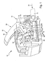
- an embodiment of a terminal is designated overall by the reference numeral 10.
- the terminal 10 serves to electrically connect at least two electrical conductors 12 to each other.
- the terminal 10 has a preferably made of plastic housing 14, with a lower housing part 16 and a housing upper part 18.
- Die Housing parts 16 and 18 are detachably connected to each other, for example by means of a latching connection, or permanently connected to each other, for example by means of a welded connection.
- the housing 14, in particular the lower housing part 16, has for each conductor 12 to be connected an insertion opening 20 for insertion of a conductor end 22, specifically in an insertion direction designated by 24 into an insertion region 26.
- the terminal 10 also has, for each conductor 12 to be connected, an actuating device designated overall by the reference numeral 28 and a clamping device, generally designated by the reference numeral 30, for contacting the conductor end 22 of a conductor 12 to be connected.
- the actuating device 28 comprises, in each case associated with a clamping device 30, an actuating lever 32, which is pivotable about a pivot axis 34.
- the actuating lever 32 has a handle portion 36 which is manually handled by a fitter.
- the actuating lever 32 also has an actuating portion 38, which is also pivoted about the pivot axis 34 when handling the handle portion 36.
- the actuating portion 38 has at its free end an actuating surface 40, which in the in FIG. 1 illustrated opening position of the actuator 28 in the manner described in more detail below with the clamping device 30 cooperates.
- the actuating lever 32 also has an angle to the actuating surface 40 arranged contact surface 42, which cooperates in a closed position of the actuator 28 in the manner described in more detail below with the clamping device 30.
- the clamping device 30 comprises a metallic, spring-elastic transmission element 44 and a metallic, preferably spring-elastic contact element 46.
- the transmission element 44 has a first portion 48 which extends between a free end 50 of the transmission element 44 and a power transmission region 52.
- the first section 48 has, on its side facing the actuating section 38 of the actuating lever 32, a surface which cooperates as a supporting surface 54 with the actuating surface 40 of the actuating section 38 and as a contact surface 56 with the contact surface 42 of the actuating section 38.
- the transmission section 52 of the transmission element 44 has a contact element 46 facing, convex curved power transmission surface 58.
- Adjoining the transfer section 52 is an oppositely curved arc section 60, which delimits the insertion region 26 towards the rear.
- the bow portion 60 is followed by a base portion 62 which extends from the arc portion 60 to the insertion opening 20 of the housing 14.
- the base portion 62 serves to support a contact rail 64, which for the electrical connection of at least mutually parallel clamping points for at least two conductor 12 to be electrically connected to each other is used.
- the transmission element 44 has an end section 66. This is provided with an opening 68 which is aligned with the insertion opening 20 of the housing and also serves to introduce the conductor end 22 of the conductor 12.
- the insertion opening 20 and / or the opening 68 is or are peripherally closed.
- end portion 66 includes a tab 70 for pivotal mounting of a bearing portion 72 of the contact element 46th
- the contact element 46 has an opening 74 for plug-in receptacle of the tab 70 (see FIG FIG. 2 ).
- the bearing section 72 is adjoined approximately at right angles by an intermediate section 76 pointing in the direction of the insertion region 26.
- a limiting section 78 adjoins, which together with the contact rail 64 delimits the insertion region 26 in such a way that, seen in the insertion direction 24, it tapers from the insertion opening 20 towards the rear end of the insertion region 26.
- the contact element 46 further has a starting from the limiting portion 78 slightly in the direction of a clamped conductor 12 angled contact area 80.
- the contact region 80 is overall flat and has a contact surface 82 on its side facing an electrical conductor 12 to be clamped.
- the latter On the side of the contact region 80 facing away from the contact surface 82, the latter has a force application surface 84.
- the force application surface 84 and the contact surface 82 have an identical size. Furthermore, it is preferable if the force application surface 84 and the contact surface 82 extend parallel to each other.
- the actuating portion 38 of the actuating lever 32 is arranged in a gap 86 which is bounded by the transmission element 44 and the contact element 46, in particular by the first portion 48 of the transmission element 44 and the limiting portion 78 of the contact element 46.
- the power transmission surface 58 of the transmission element 44 is lifted from the force application surface 84 of the contact portion 80 of the contact element 46. This is achieved in that the actuating portion 38 with its actuating surface 40, the support surface 54 of the first portion 48 of the transmission element 44 is supported. Due to the spatial distance between the force transmission surface 58 and the force application surface 84, the contact element 46 in the storage between bearing portion 72 and tab 70 is pivotally movable so that a conductor end 22 of an electrical conductor 12 is practically force-free in the insertion region 26 can be inserted.
- Such an electrical conductor may be a solid wire or a stranded wire.
- the actuator 28 When the actuator 28 is moved out of its open position into the closed position (see FIG. 2 ), the support surface 54 of the first portion 48 of the transmission element 44 rolls on the Operating section 38 from until the support surface 54 is effective as a contact surface 56 and abuts against the contact surface 42 of the actuating lever 32.
- the transmission region 52 due to the residual stress of the transmission element 44, is displaced in the direction of the contact element 46.
- the force transmission surface 58 comes into contact with the force application surface 84 of the contact region 80, so that a pressure force exerted on the force application surface 84 by the force transmission surface 84 is transmitted through the contact region 80 to the contact surface 82.
- the force transmitted to the contact surface 82 is received by the contact rail 64 in a non-fully inserted state of a conductor end 22.
- the compressive force transmitted to the contact surface 82 is inserted into the conductor end 22 so that the conductor end 22 is clamped between the contact surface 82 and the contact rail 64.
- the conductor 12 is a solid wire
- FIG. 3 another embodiment of a terminal 10 is shown. Regarding the construction and the operation of the terminal according to FIG. 3 Turns to the above description of the terminal 10 according to FIGS. 1 and 2 Referenced. Below only differences between the terminals 10 according to FIG. 3 on the one hand and the terminal 10 according to FIGS. 1 and 2 on the other hand.
- the transmission element 44 and the contact element 46 are formed integrally with each other.
- the contact element 46 is connected in a curved connecting portion 90 with the transmission element 44.
- the transfer section 90 allows pivotal movement of the contact element 46 relative to the transfer element 44.
- the contact element 46 may, as in FIG. 3 shown, be completely flat so that the contact portion 80 and the limiting portion 78 merge into one another. But it is also possible that the contact element 46 has a shape in which the contact region 80 and the boundary region 78 are arranged at an angle relative to each other (see FIGS. 1 and 2 ).
Landscapes
- Coupling Device And Connection With Printed Circuit (AREA)
- Connections Arranged To Contact A Plurality Of Conductors (AREA)
- Details Of Connecting Devices For Male And Female Coupling (AREA)
Applications Claiming Priority (1)
| Application Number | Priority Date | Filing Date | Title |
|---|---|---|---|
| DE102011081329A DE102011081329A1 (de) | 2011-08-22 | 2011-08-22 | Anschlussklemme zum elektrischen Anschluss von Leitern |
Publications (2)
| Publication Number | Publication Date |
|---|---|
| EP2562878A2 true EP2562878A2 (fr) | 2013-02-27 |
| EP2562878A3 EP2562878A3 (fr) | 2014-01-08 |
Family
ID=46679147
Family Applications (1)
| Application Number | Title | Priority Date | Filing Date |
|---|---|---|---|
| EP12178498.7A Withdrawn EP2562878A3 (fr) | 2011-08-22 | 2012-07-30 | Borne de connexion destinée au raccordement électrique de conducteurs |
Country Status (2)
| Country | Link |
|---|---|
| EP (1) | EP2562878A3 (fr) |
| DE (1) | DE102011081329A1 (fr) |
Cited By (7)
| Publication number | Priority date | Publication date | Assignee | Title |
|---|---|---|---|---|
| WO2014186813A1 (fr) * | 2013-05-24 | 2014-11-27 | Tridonic Connection Technology Gmbh & Co Kg | Borne de raccordement ou de connexion |
| EP2843765A1 (fr) * | 2013-08-30 | 2015-03-04 | Switchlab Inc. | Structure de borne |
| DE102015112433A1 (de) | 2015-07-29 | 2017-02-02 | Wago Verwaltungsgesellschaft Mbh | Leiteranschlussklemme |
| CN108075252A (zh) * | 2017-07-12 | 2018-05-25 | 德尔福中央电气(上海)有限公司 | 电连接器 |
| CN111180913A (zh) * | 2020-03-02 | 2020-05-19 | 町洋机电(中国)有限公司 | 直插式侧面按压手把连接器 |
| EP3485536B1 (fr) * | 2016-07-13 | 2024-12-11 | Phoenix Contact GmbH & Co. KG | Borne de connexion |
| DE202024102562U1 (de) * | 2024-05-17 | 2025-08-20 | WAGO Verwaltungsgesellschaft mit beschränkter Haftung | Federkraftklemmanschluss und Leiteranschlussklemme |
Families Citing this family (1)
| Publication number | Priority date | Publication date | Assignee | Title |
|---|---|---|---|---|
| DE102013215143B4 (de) * | 2013-07-04 | 2015-04-16 | Robert Bosch Gmbh | Klemmkontakt zur elektrischen Kontaktierung elektrischer Bauelemente |
Citations (1)
| Publication number | Priority date | Publication date | Assignee | Title |
|---|---|---|---|---|
| US3671924A (en) | 1969-09-24 | 1972-06-20 | Hideo Nagano | Electric connector |
Family Cites Families (7)
| Publication number | Priority date | Publication date | Assignee | Title |
|---|---|---|---|---|
| DE692481C (fr) * | 1938-06-09 | 1940-06-20 | Siemens Schuckertwerke Akt Ges | |
| DE698229C (de) * | 1938-09-10 | 1940-11-05 | Siemens Schuckertwerke Akt Ges | Aufreihtrennstelle fuer elektrische Leitungen |
| DE709780C (de) * | 1939-04-13 | 1941-08-27 | Siemens Schuckertwerke Akt Ges | Klemmvorrichtung fuer elektrische Leitungen |
| FR2754640B1 (fr) * | 1996-10-16 | 1998-12-18 | Legrand Sa | Borne de connexion automatique, et appareil electrique equipe d'une telle borne de connexion |
| DE10037550A1 (de) * | 2000-08-02 | 2002-02-14 | Luetze Friedrich Elektro | Kabelanschlussvorrichtung |
| FR2824960B1 (fr) * | 2001-05-15 | 2003-08-15 | Entrelec | Dispositif de raccordement a poussoir |
| DE102008039868A1 (de) * | 2008-08-27 | 2010-03-04 | Phoenix Contact Gmbh & Co. Kg | Elektrische Anschlußklemme |
-
2011
- 2011-08-22 DE DE102011081329A patent/DE102011081329A1/de not_active Withdrawn
-
2012
- 2012-07-30 EP EP12178498.7A patent/EP2562878A3/fr not_active Withdrawn
Patent Citations (1)
| Publication number | Priority date | Publication date | Assignee | Title |
|---|---|---|---|---|
| US3671924A (en) | 1969-09-24 | 1972-06-20 | Hideo Nagano | Electric connector |
Cited By (10)
| Publication number | Priority date | Publication date | Assignee | Title |
|---|---|---|---|---|
| WO2014186813A1 (fr) * | 2013-05-24 | 2014-11-27 | Tridonic Connection Technology Gmbh & Co Kg | Borne de raccordement ou de connexion |
| EP2843765A1 (fr) * | 2013-08-30 | 2015-03-04 | Switchlab Inc. | Structure de borne |
| DE102015112433A1 (de) | 2015-07-29 | 2017-02-02 | Wago Verwaltungsgesellschaft Mbh | Leiteranschlussklemme |
| WO2017016751A1 (fr) | 2015-07-29 | 2017-02-02 | Wago Verwaltungsgesellschaft Mbh | Borne de connexion de conducteur |
| DE102015112433B4 (de) * | 2015-07-29 | 2021-06-10 | Wago Verwaltungsgesellschaft Mbh | Leiteranschlussklemme |
| EP3485536B1 (fr) * | 2016-07-13 | 2024-12-11 | Phoenix Contact GmbH & Co. KG | Borne de connexion |
| CN108075252A (zh) * | 2017-07-12 | 2018-05-25 | 德尔福中央电气(上海)有限公司 | 电连接器 |
| CN108075252B (zh) * | 2017-07-12 | 2023-08-01 | 安波福中央电气(上海)有限公司 | 电连接器 |
| CN111180913A (zh) * | 2020-03-02 | 2020-05-19 | 町洋机电(中国)有限公司 | 直插式侧面按压手把连接器 |
| DE202024102562U1 (de) * | 2024-05-17 | 2025-08-20 | WAGO Verwaltungsgesellschaft mit beschränkter Haftung | Federkraftklemmanschluss und Leiteranschlussklemme |
Also Published As
| Publication number | Publication date |
|---|---|
| DE102011081329A9 (de) | 2013-06-13 |
| DE102011081329A1 (de) | 2013-02-28 |
| EP2562878A3 (fr) | 2014-01-08 |
Similar Documents
| Publication | Publication Date | Title |
|---|---|---|
| EP2562878A2 (fr) | Borne de connexion destinée au raccordement électrique de conducteurs | |
| EP3504755B2 (fr) | Borne à ressort | |
| EP2400595B1 (fr) | Borne de connexion | |
| EP2768079B1 (fr) | Borne de connexion électrique à ressort | |
| EP2381536B1 (fr) | Pinces de contact et connexion dotée de pinces de contact | |
| DE102019127232B3 (de) | Anschlusseinrichtung zum Anschließen einer elektrischen Leitung | |
| EP2810341B1 (fr) | Contact tubulaire pour un connecteur électrique à force d'insertion nulle | |
| EP2729991A1 (fr) | Borne de connexion électrique | |
| WO2010031491A2 (fr) | Borne de connexion électrique | |
| EP3586404B1 (fr) | Connexion élastique et connecteur rond comportant une pluralité de connexions élastiques | |
| EP2987206A1 (fr) | Raccord électrique enfichable actionnable par genouillière permettant le serrage de l'extrémité du fil avec la barre collectrice | |
| EP3028344A1 (fr) | Borne de connexion électrique et procédé | |
| DE102017111733A1 (de) | Federkraftklemme für Leiter | |
| EP3050167A1 (fr) | Borne de connexion électrique | |
| EP2577805A1 (fr) | Élément de contact pour ensemble connecteur | |
| WO2020259926A1 (fr) | Borne de connexion électrique | |
| EP3595090A1 (fr) | Borne de connexion conductrice | |
| DE102017117509A1 (de) | Elektrisches Gerät | |
| WO2023213511A1 (fr) | Dispositif de connexion conçu sous la forme d'une borne à ressort pour connecter un conducteur | |
| DE202015102045U1 (de) | Federkraftklemmelement mit Schwenkhebel | |
| DE102016107162A1 (de) | Elektrische Kontaktklemme und Verwendung einer solchen | |
| EP3583663B1 (fr) | Dispositif de connexion pour extrémité de conducteur | |
| EP3038213B1 (fr) | Borne de connection de cable destinee a serrer au moins un conducteur electrique | |
| WO2017016751A1 (fr) | Borne de connexion de conducteur | |
| WO2016087433A1 (fr) | Système de connexion pour un conducteur |
Legal Events
| Date | Code | Title | Description |
|---|---|---|---|
| PUAI | Public reference made under article 153(3) epc to a published international application that has entered the european phase |
Free format text: ORIGINAL CODE: 0009012 |
|
| AK | Designated contracting states |
Kind code of ref document: A2 Designated state(s): AL AT BE BG CH CY CZ DE DK EE ES FI FR GB GR HR HU IE IS IT LI LT LU LV MC MK MT NL NO PL PT RO RS SE SI SK SM TR |
|
| AX | Request for extension of the european patent |
Extension state: BA ME |
|
| PUAL | Search report despatched |
Free format text: ORIGINAL CODE: 0009013 |
|
| AK | Designated contracting states |
Kind code of ref document: A3 Designated state(s): AL AT BE BG CH CY CZ DE DK EE ES FI FR GB GR HR HU IE IS IT LI LT LU LV MC MK MT NL NO PL PT RO RS SE SI SK SM TR |
|
| AX | Request for extension of the european patent |
Extension state: BA ME |
|
| RIC1 | Information provided on ipc code assigned before grant |
Ipc: H01R 4/50 20060101ALI20131129BHEP Ipc: H01R 4/48 20060101AFI20131129BHEP |
|
| 17P | Request for examination filed |
Effective date: 20140702 |
|
| RBV | Designated contracting states (corrected) |
Designated state(s): AL AT BE BG CH CY CZ DE DK EE ES FI FR GB GR HR HU IE IS IT LI LT LU LV MC MK MT NL NO PL PT RO RS SE SI SK SM TR |
|
| GRAP | Despatch of communication of intention to grant a patent |
Free format text: ORIGINAL CODE: EPIDOSNIGR1 |
|
| INTG | Intention to grant announced |
Effective date: 20160330 |
|
| RIN1 | Information on inventor provided before grant (corrected) |
Inventor name: ALBUKREK, YILMAZ |
|
| RAP1 | Party data changed (applicant data changed or rights of an application transferred) |
Owner name: BIMED TEKNIK ALETLER SANAYI VE TICARET A.S. |
|
| STAA | Information on the status of an ep patent application or granted ep patent |
Free format text: STATUS: THE APPLICATION IS DEEMED TO BE WITHDRAWN |
|
| 18D | Application deemed to be withdrawn |
Effective date: 20160810 |