EP2562886A1 - Verbinder - Google Patents
Verbinder Download PDFInfo
- Publication number
- EP2562886A1 EP2562886A1 EP11771978A EP11771978A EP2562886A1 EP 2562886 A1 EP2562886 A1 EP 2562886A1 EP 11771978 A EP11771978 A EP 11771978A EP 11771978 A EP11771978 A EP 11771978A EP 2562886 A1 EP2562886 A1 EP 2562886A1
- Authority
- EP
- European Patent Office
- Prior art keywords
- connector
- filler
- filling chamber
- holder
- rib
- Prior art date
- Legal status (The legal status is an assumption and is not a legal conclusion. Google has not performed a legal analysis and makes no representation as to the accuracy of the status listed.)
- Granted
Links
Images

Classifications
-
- H—ELECTRICITY
- H01—ELECTRIC ELEMENTS
- H01R—ELECTRICALLY-CONDUCTIVE CONNECTIONS; STRUCTURAL ASSOCIATIONS OF A PLURALITY OF MUTUALLY-INSULATED ELECTRICAL CONNECTING ELEMENTS; COUPLING DEVICES; CURRENT COLLECTORS
- H01R13/00—Details of coupling devices of the kinds covered by groups H01R12/70 or H01R24/00 - H01R33/00
- H01R13/46—Bases; Cases
- H01R13/52—Dustproof, splashproof, drip-proof, waterproof, or flameproof cases
- H01R13/521—Sealing between contact members and housing, e.g. sealing insert
-
- H—ELECTRICITY
- H01—ELECTRIC ELEMENTS
- H01R—ELECTRICALLY-CONDUCTIVE CONNECTIONS; STRUCTURAL ASSOCIATIONS OF A PLURALITY OF MUTUALLY-INSULATED ELECTRICAL CONNECTING ELEMENTS; COUPLING DEVICES; CURRENT COLLECTORS
- H01R13/00—Details of coupling devices of the kinds covered by groups H01R12/70 or H01R24/00 - H01R33/00
- H01R13/46—Bases; Cases
- H01R13/52—Dustproof, splashproof, drip-proof, waterproof, or flameproof cases
- H01R13/5216—Dustproof, splashproof, drip-proof, waterproof, or flameproof cases characterised by the sealing material, e.g. gels or resins
-
- H—ELECTRICITY
- H01—ELECTRIC ELEMENTS
- H01R—ELECTRICALLY-CONDUCTIVE CONNECTIONS; STRUCTURAL ASSOCIATIONS OF A PLURALITY OF MUTUALLY-INSULATED ELECTRICAL CONNECTING ELEMENTS; COUPLING DEVICES; CURRENT COLLECTORS
- H01R13/00—Details of coupling devices of the kinds covered by groups H01R12/70 or H01R24/00 - H01R33/00
- H01R13/40—Securing contact members in or to a base or case; Insulating of contact members
- H01R13/42—Securing in a demountable manner
- H01R13/436—Securing a plurality of contact members by one locking piece or operation
- H01R13/4361—Insertion of locking piece perpendicular to direction of contact insertion
-
- H—ELECTRICITY
- H01—ELECTRIC ELEMENTS
- H01R—ELECTRICALLY-CONDUCTIVE CONNECTIONS; STRUCTURAL ASSOCIATIONS OF A PLURALITY OF MUTUALLY-INSULATED ELECTRICAL CONNECTING ELEMENTS; COUPLING DEVICES; CURRENT COLLECTORS
- H01R13/00—Details of coupling devices of the kinds covered by groups H01R12/70 or H01R24/00 - H01R33/00
- H01R13/46—Bases; Cases
- H01R13/53—Bases or cases for heavy duty; Bases or cases for high voltage with means for preventing corona or arcing
Definitions
- the present invention relates to a connector which is waterproofed using a curable filler.
- Patent Literatures 1 to 3 disclose a connector which is waterproofed by using a filler and curing the filler, for example.
- a connector housing configuring the connector is formed with a filling chamber for filling the filler.
- the filler is filled into the filling chamber and then cured. In a cured state, it is possible to prevent infiltration of moisture, etc., to an electrical connection part via an electric wire.
- the existing connector has a problem that the cost is increased as a filling amount of the filler increases, in a case where the filler is relatively expensive.
- the present invention has been made to solve the above-described problems, and an object of the present invention is to provide a connector capable of preventing an operator from touching a filler. Another object of the present invention is to provide a connector capable of reducing a filling amount of a filler to thus cut down the cost.
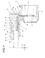
- a connector including: a terminal fitting provided at an end of an electric wire; and a connector housing including a terminal accommodation part in which the terminal fitting is accommodated, wherein the connector is to be waterproofed by a filler filled into a filling chamber of the connector housing, the filling chamber is arranged to allow at least a wire connection part and a continuous part which is continuous to an electrical contact part and continuous to the wire connection part in the terminal fitting to be immersed in the filler, and the connector further includes a holder fitted in the connector housing and engaged with the electric wire which is drawn from the filling chamber, wherein a rib is formed integrally with the holder, the rib being provided across an opening of the filling chamber and partly being immersed in the filler.
- the connector having the configuration (1) mentioned above since the rib is formed in the holder, it is possible to prevent an operator's finger from touching the filler. Further, according to the configuration (1) mentioned above, since the rib is provided and therefore the opening of the filling chamber is not entirely covered, the filler is visible so that it is possible to confirm whether the filler is completely cured or not. Further, according to the configuration (1) mentioned above, since a portion of the rib is partly immersed in the filler, it is possible to reduce the filling amount of the filler by an amount corresponding to the immersed part.
- the connector having the configuration (2) mentioned above it is possible to detect that the terminal fitting is in a incomplete-fitting state with respect to the terminal accommodation part if the extension part is brought into contact with the terminal fitting when the holder is fitted into the connector housing. Further, according to the configuration (2) mentioned above, it is possible to reduce the filling amount of the filler by a protruding amount of the extension part.
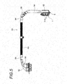
- a connector 1 according to the present embodiment is provided at one end of a wire harness 51 (the wire harness 51 is described as an example).
- the wire harness 51 is intended for use in high voltage and includes three high-voltage electric wires 2 (see Fig. 1 ) which are covered with a braid 52 in group.
- Protective members such as a corrugated tube 53, a cylinder member 54 and a protector 55 are provided on an outer side of the braid 52.
- the connector 1 is described.
- the connector 1 is intended for use in high voltage and configured as a relatively large connector.
- the connector 1 includes a conductive terminal fitting 3 provided at an end of each high-voltage electric wire 2 (electric wire), a connector housing 4 made of insulation resin, a resin holder 5 fitted into the connector housing 4 and a metal fixed part 6 (see Fig. 5 ) which is fixed to a mating housing, for example.
- the connector 1 has been subjected to a waterproofing (waterproofing will be described later).
- the terminal fitting 3 includes a wire connection part 7 to which the end of the high-voltage electric wire 2 is connected and an electrical contact part 8 which is brought into contact and connected with a mating terminal (not shown).
- the terminal fitting 3 has such a shape that a continuous part 9 extended between the wire connection part 7 and the electrical contact part 8 is bent at a substantially right angle and thus forms L-shape.
- the wire connection part 7 is formed so that the conductor of the high-voltage electric wire 2 can be connected to the wire connection part 7 by crimping.
- Bolt insertion through-holes 10 are formed at predetermined positions of the electrical contact part 8.
- a fitting part (a reference numeral thereof is omitted) for a terminal accommodation part 14 (which will be described later) of the connector housing 4 is formed between the bolt insertion through-holes 10 and the continuous part 9.
- the fitting part is a small claw-like protrusion and formed in plural.
- the fitting part is fitted into the terminal accommodation part 14, so that the terminal fitting 3 is prevented from being separated.
- an incomplete-fitting state is caused.
- the incomplete-fitting state can be mentioned as the cause of failure such as separation. In the present embodiment, the incomplete-fitting state can be detected, which will be described later.
- the connector housing 4 is a resin molding product formed by an injection molding and includes a mating fitting part 11 for a mating housing (not shown), a waterproofing part 12 which is subjected to a waterproofing and an interconnecting part 13 that interconnects the mating fitting part 11 and the waterproofing part 12.
- the connector housing 4 has a shape shown in the drawings, for example.
- the mating fitting part 11 is formed so that the electrical contact part 8 of the terminal fitting 3 is exposed to an internal space of the mating fitting part 11.
- the terminal accommodation part 14 is provided at the interconnecting part 13 provided between the mating fitting part 11 and the waterproofing part 12.
- the terminal accommodation part 14 is formed to pass through the interior of the interconnecting part 13.
- the terminal accommodation part 14 is formed to allow the electrical contact part 8 of the terminal fitting 3 to pass therethrough from the waterproofing part 12 side and also to allow a fitting part (a reference numeral thereof is omitted) of the terminal fitting 3 to be hooked and locked thereto.
- the waterproofing part 12 is a part to be subjected to the waterproofing as mentioned above and is provided with a filling chamber 15 for filling the filler.
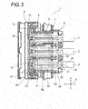
- the filling chamber 15 is partitioned by a front wall 16, right and left side walls 17 and two partition walls 18 which are positioned between the right and left side walls 17, where a direction of arrow P is defined as a front-rear direction, a direction of arrow Q is defined as an upper-lower direction and a direction of R is defined as a right-left direction in the drawings.
- the waterproofing part 12 (the filling chamber 15) is formed to open in a rear side and an upper side and to have a bottom 19. One end of the terminal accommodation part 14 is opened to the bottom 19 in the vicinity of the front wall 16.
- the waterproofing part 12 (the filling chamber 15) is configured to allow the terminal fitting 3 to be accommodated and mounted through the upper opening.
- the upper opening is formed in consideration of a shape of the wire connection part 7 and the continuous part 9 of the terminal fitting 3, when seen from a plan view.
- a holder fitting part 20 is formed at a rear side of the waterproofing part 12.
- the holder fitting part 20 is a part into which the holder 5 is fitted.
- the holder fitting part 20 includes a holder insertion part 21 and a holder locking part 22.
- the holder insertion part 21 is formed to correspond to a covering engagement part 28 (will be described later) of the holder 5.
- the holder locking part 22 is a claw-like protrusion and is formed to allow a locking arm part 29 (will be described later) of the holder 5 to be hooked and locked thereto.
- the holder locking part 22 is arranged on outer surfaces of the right and left side walls 17.
- the waterproofing part 12 includes rib locking parts 23 to which ribs 26 (will be described later) of the holder 5 are locked.
- the rib locking parts 23 are respectively formed at the right and left side walls 17 and two partition walls 18 at the front side of the waterproofing part 12.
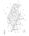
- the holder 5 is a resin molding product formed by the injection molding similarly to the connector housing 4 and includes a holder body 25, a plurality of ribs 26 formed integrally with the holder body 25 and a second rib 27 formed over the plurality of ribs 26.
- the holder body 25 is fitted into the waterproofing part 12 of the connector housing 4 and engaged with a covering part 24 of the high-voltage electric wire 2 which is drawn from the filling chamber 15.
- the holder 5 has a shape shown in fig. 4 .
- the holder body 25 includes covering engagement parts 28 which are inserted into the holder insertion parts 21 of the connector housing 4 and engaged with the covering part 24 of the high-voltage electric wire 2, and locking arm parts 29 which are hooked and locked to the holder locking parts 22 of the connector housing 4.
- the covering engagement parts 28 are formed to protrude according to the number of the high-voltage electric wires 2.
- Semi-cylindrical pressing grooves 30 which are in close contact with the covering part 24 of the high-voltage electric wire 2 are formed at a tip of the covering engagement parts 28.
- the covering engagement parts 28 and the pressing grooves 30 can be provided for preventing leakage of the filler when the filler is filled into the filling chamber 15.
- the locking arm parts 29 are formed at positions of both lateral sides of the holder body 25.
- the locking arm parts 29 are formed in an arm shape which is a substantially frame-shape.
- the ribs 26 are formed across an upper opening of the filling chamber 15 and also to extend to a position corresponding to the continuous part 9 (or the wire connection part 7) of the terminal fitting 3.
- the ribs 26 are arranged so that a gap between the rib 26 and the side wall 17 or the partition wall 18 is narrower than a finger width of an operator.
- the ribs 26 are provided to prevent an operator from accidentally putting a finger into the filling chamber and also to prevent an operator from touching the filler before being cured which is filled into the filling chamber 15.
- the ribs 26 may have a lattice shape, for example.
- the ribs 26 are configured so that a tip (free end) thereof is supported on the front wall 16 of the waterproofing part 12.
- a lower side of the rib 26 is formed as a filler immersed part 31 (corresponding to a part of the rib described in Claims).
- the filler immersed part 31 is a part which is immersed in the filler filled into the filling chamber 15 and intended for reducing the filling amount of the filler by an amount corresponding to the immersion.
- an extension part 32 extending toward the bottom 19 of the filling chamber 15 is integrally formed at a lower side of the rib 26.
- the extension part 32 is formed as a part which detects the incomplete-fitting state of the terminal fitting 3.
- the extension part 32 is formed at a position corresponding to the continuous part 9 of the terminal fitting 3.
- the extension part 32 may be formed at a position corresponding to the wire connection part 7.
- the extension part 32 is formed as a part for determining that the terminal fitting 3 is in the incomplete-fitting state with respect to the terminal accommodation part 14 if the extension part 32 is brought into contact with the terminal fitting 3 when the holder 5 is fitted into the connector housing 4. Since the extension part 32 protrudes downward beyond the filler immersed part 31, it is possible to reduce the filling amount of the filler by a protruding amount of the extension part 32.
- the second rib 27 is formed to keep a gap between the plurality of ribs 26.
- the second rib 27 is formed with a plurality of locked parts 33 which are locked to the rib locking parts 23 of the connector housing 4.
- the high-voltage electric wire 2 is engaged with the covering engagement part 28 of the holder 5 and thus is urged.
- the covering engagement part 28 closes the rear opening of the waterproofing part 12 (the filling chamber 15).
- the ribs 26 traverse an upper opening of the filling chamber 15.
- the holder 5 does not cover the entire upper opening of the filling chamber 15, it is possible to see the filler and thus to confirm whether the curing is completed or not.
Landscapes
- Chemical & Material Sciences (AREA)
- Dispersion Chemistry (AREA)
- Connector Housings Or Holding Contact Members (AREA)
Applications Claiming Priority (2)
| Application Number | Priority Date | Filing Date | Title |
|---|---|---|---|
| JP2010096666A JP5579490B2 (ja) | 2010-04-20 | 2010-04-20 | コネクタ |
| PCT/JP2011/059553 WO2011132643A1 (ja) | 2010-04-20 | 2011-04-18 | コネクタ |
Publications (3)
| Publication Number | Publication Date |
|---|---|
| EP2562886A1 true EP2562886A1 (de) | 2013-02-27 |
| EP2562886A4 EP2562886A4 (de) | 2014-06-25 |
| EP2562886B1 EP2562886B1 (de) | 2019-04-03 |
Family
ID=44834162
Family Applications (1)
| Application Number | Title | Priority Date | Filing Date |
|---|---|---|---|
| EP11771978.1A Active EP2562886B1 (de) | 2010-04-20 | 2011-04-18 | Verbinder |
Country Status (5)
| Country | Link |
|---|---|
| US (1) | US9083108B2 (de) |
| EP (1) | EP2562886B1 (de) |
| JP (1) | JP5579490B2 (de) |
| CN (1) | CN102859800B (de) |
| WO (1) | WO2011132643A1 (de) |
Cited By (1)
| Publication number | Priority date | Publication date | Assignee | Title |
|---|---|---|---|---|
| EP2874240A4 (de) * | 2012-07-12 | 2016-03-16 | Furukawa Electric Co Ltd | Stecker und steckeranschlussstruktur |
Families Citing this family (7)
| Publication number | Priority date | Publication date | Assignee | Title |
|---|---|---|---|---|
| JP6118146B2 (ja) * | 2013-03-14 | 2017-04-19 | 矢崎総業株式会社 | 防水コネクタ |
| JP6340411B2 (ja) * | 2013-03-29 | 2018-06-06 | モレックス エルエルシー | Tpaを備えるコネクタ |
| US9960506B2 (en) * | 2015-09-14 | 2018-05-01 | Qfe 002 Llc | Bend radius adapters and methods of forming same |
| KR102814047B1 (ko) * | 2020-11-17 | 2025-05-29 | 현대자동차주식회사 | 배선 커넥터 조립체 |
| US11424559B1 (en) * | 2021-05-07 | 2022-08-23 | GM Global Technology Operations LLC | Strain relief for battery cable terminals |
| JP2024158360A (ja) * | 2023-04-27 | 2024-11-08 | 株式会社Nhvコーポレーション | 高電圧ケーブル接続具及び高電圧ケーブル接続具に対する薬剤の塗布方法 |
| JP2024158359A (ja) * | 2023-04-27 | 2024-11-08 | 株式会社Nhvコーポレーション | 高電圧ケーブル接続具 |
Family Cites Families (10)
| Publication number | Priority date | Publication date | Assignee | Title |
|---|---|---|---|---|
| JP2713846B2 (ja) | 1992-12-28 | 1998-02-16 | 矢崎総業株式会社 | 充填剤注入型コネクタ装置 |
| FR2714536B1 (fr) * | 1993-12-27 | 1996-01-19 | Cinch Connecteurs Sa | Perfectionnements aux éléments de boîtiers de connecteurs électriques. |
| JP3440711B2 (ja) | 1996-08-26 | 2003-08-25 | 矢崎総業株式会社 | オートマチックトランスミッション用コネクタ及びその組立方法 |
| JP3459034B2 (ja) * | 1997-10-22 | 2003-10-20 | 矢崎総業株式会社 | 圧接コネクタのカバー固定構造 |
| JP2003317876A (ja) | 2002-04-25 | 2003-11-07 | Yazaki Corp | 電磁波シールド構造 |
| JP2004349026A (ja) * | 2003-05-20 | 2004-12-09 | Yazaki Corp | ホルダ及びコネクタ |
| JP2005026102A (ja) * | 2003-07-03 | 2005-01-27 | Fujikura Ltd | 圧接コネクタ |
| JP4271092B2 (ja) * | 2004-06-29 | 2009-06-03 | 株式会社フジクラ | 圧接コネクタ |
| JP2006156052A (ja) | 2004-11-26 | 2006-06-15 | Yazaki Corp | 高圧電線の接続構造及び高圧電線の接続方法 |
| JP5195225B2 (ja) * | 2008-09-25 | 2013-05-08 | 住友電装株式会社 | 防水装置 |
-
2010
- 2010-04-20 JP JP2010096666A patent/JP5579490B2/ja active Active
-
2011
- 2011-04-18 CN CN201180020310.4A patent/CN102859800B/zh active Active
- 2011-04-18 WO PCT/JP2011/059553 patent/WO2011132643A1/ja not_active Ceased
- 2011-04-18 US US13/642,315 patent/US9083108B2/en active Active
- 2011-04-18 EP EP11771978.1A patent/EP2562886B1/de active Active
Cited By (1)
| Publication number | Priority date | Publication date | Assignee | Title |
|---|---|---|---|---|
| EP2874240A4 (de) * | 2012-07-12 | 2016-03-16 | Furukawa Electric Co Ltd | Stecker und steckeranschlussstruktur |
Also Published As
| Publication number | Publication date |
|---|---|
| JP2011228112A (ja) | 2011-11-10 |
| WO2011132643A1 (ja) | 2011-10-27 |
| US9083108B2 (en) | 2015-07-14 |
| US20130065430A1 (en) | 2013-03-14 |
| CN102859800B (zh) | 2016-04-06 |
| EP2562886B1 (de) | 2019-04-03 |
| CN102859800A (zh) | 2013-01-02 |
| EP2562886A4 (de) | 2014-06-25 |
| JP5579490B2 (ja) | 2014-08-27 |
Similar Documents
| Publication | Publication Date | Title |
|---|---|---|
| EP2562886B1 (de) | Verbinder | |
| EP3726661B1 (de) | Hochspannungsfingerschutz | |
| CN108370122B (zh) | 屏蔽连接器、以及带连接器的屏蔽电缆 | |
| JP6368504B2 (ja) | 電気コネクタ | |
| CN102377141B (zh) | 电气接线盒 | |
| CN109565129A (zh) | 电力连接器系统 | |
| EP2980931B1 (de) | Elektrischer steckverbinder | |
| CN107210565A (zh) | 屏蔽连接器 | |
| EP2874240B1 (de) | Stecker und steckeranschlussstruktur | |
| WO2013178773A1 (en) | Electrical connector | |
| WO2012176935A1 (en) | Busbar module unit | |
| CN103682882A (zh) | 连接器连接结构 | |
| CN108370121B (zh) | 屏蔽连接器以及带有连接器的屏蔽电缆 | |
| KR101645114B1 (ko) | 와이어 하네스 | |
| KR101340811B1 (ko) | 커넥터 | |
| US8714992B2 (en) | Receptacle connector having a base part with sealing lips fitted in a housing wall | |
| EP2866302B1 (de) | Struktur umfassend einen schneidklemmkontakt und eine beschichtete elektrische leitung | |
| WO2013178433A1 (en) | Interconnection assembly for vehicle devices and method of interconnection | |
| JP6141451B2 (ja) | シールドコネクタ | |
| CN104604062B (zh) | 电接线盒 | |
| CN104350646B (zh) | 连接器 | |
| CN102394419B (zh) | 连接器 | |
| JP4913557B2 (ja) | コネクタ押し込みプロテクタ | |
| JP2015011945A (ja) | コネクタ | |
| CN104115346A (zh) | 接合端子和接合连接器 |
Legal Events
| Date | Code | Title | Description |
|---|---|---|---|
| PUAI | Public reference made under article 153(3) epc to a published international application that has entered the european phase |
Free format text: ORIGINAL CODE: 0009012 |
|
| 17P | Request for examination filed |
Effective date: 20121019 |
|
| AK | Designated contracting states |
Kind code of ref document: A1 Designated state(s): AL AT BE BG CH CY CZ DE DK EE ES FI FR GB GR HR HU IE IS IT LI LT LU LV MC MK MT NL NO PL PT RO RS SE SI SK SM TR |
|
| DAX | Request for extension of the european patent (deleted) | ||
| A4 | Supplementary search report drawn up and despatched |
Effective date: 20140522 |
|
| RIC1 | Information provided on ipc code assigned before grant |
Ipc: H01R 13/52 20060101AFI20140516BHEP Ipc: H01R 4/70 20060101ALI20140516BHEP Ipc: H01R 13/436 20060101ALN20140516BHEP Ipc: H01R 13/53 20060101ALN20140516BHEP |
|
| 17Q | First examination report despatched |
Effective date: 20160419 |
|
| STAA | Information on the status of an ep patent application or granted ep patent |
Free format text: STATUS: EXAMINATION IS IN PROGRESS |
|
| RIC1 | Information provided on ipc code assigned before grant |
Ipc: H01R 13/52 20060101AFI20161117BHEP Ipc: H01R 13/53 20060101ALN20161117BHEP Ipc: H01R 4/70 20060101ALI20161117BHEP Ipc: H01R 13/436 20060101ALN20161117BHEP |
|
| GRAP | Despatch of communication of intention to grant a patent |
Free format text: ORIGINAL CODE: EPIDOSNIGR1 |
|
| STAA | Information on the status of an ep patent application or granted ep patent |
Free format text: STATUS: GRANT OF PATENT IS INTENDED |
|
| RIC1 | Information provided on ipc code assigned before grant |
Ipc: H01R 13/436 20060101ALN20181031BHEP Ipc: H01R 13/53 20060101ALN20181031BHEP Ipc: H01R 4/70 20060101ALI20181031BHEP Ipc: H01R 13/52 20060101AFI20181031BHEP |
|
| RIC1 | Information provided on ipc code assigned before grant |
Ipc: H01R 13/436 20060101ALN20181108BHEP Ipc: H01R 13/52 20060101AFI20181108BHEP Ipc: H01R 4/70 20060101ALI20181108BHEP Ipc: H01R 13/53 20060101ALN20181108BHEP |
|
| INTG | Intention to grant announced |
Effective date: 20181126 |
|
| GRAS | Grant fee paid |
Free format text: ORIGINAL CODE: EPIDOSNIGR3 |
|
| GRAA | (expected) grant |
Free format text: ORIGINAL CODE: 0009210 |
|
| STAA | Information on the status of an ep patent application or granted ep patent |
Free format text: STATUS: THE PATENT HAS BEEN GRANTED |
|
| AK | Designated contracting states |
Kind code of ref document: B1 Designated state(s): AL AT BE BG CH CY CZ DE DK EE ES FI FR GB GR HR HU IE IS IT LI LT LU LV MC MK MT NL NO PL PT RO RS SE SI SK SM TR |
|
| REG | Reference to a national code |
Ref country code: GB Ref legal event code: FG4D |
|
| REG | Reference to a national code |
Ref country code: CH Ref legal event code: EP Ref country code: AT Ref legal event code: REF Ref document number: 1116911 Country of ref document: AT Kind code of ref document: T Effective date: 20190415 |
|
| REG | Reference to a national code |
Ref country code: DE Ref legal event code: R096 Ref document number: 602011057774 Country of ref document: DE |
|
| REG | Reference to a national code |
Ref country code: IE Ref legal event code: FG4D |
|
| REG | Reference to a national code |
Ref country code: NL Ref legal event code: MP Effective date: 20190403 |
|
| REG | Reference to a national code |
Ref country code: LT Ref legal event code: MG4D |
|
| REG | Reference to a national code |
Ref country code: AT Ref legal event code: MK05 Ref document number: 1116911 Country of ref document: AT Kind code of ref document: T Effective date: 20190403 |
|
| PG25 | Lapsed in a contracting state [announced via postgrant information from national office to epo] |
Ref country code: NL Free format text: LAPSE BECAUSE OF FAILURE TO SUBMIT A TRANSLATION OF THE DESCRIPTION OR TO PAY THE FEE WITHIN THE PRESCRIBED TIME-LIMIT Effective date: 20190403 |
|
| PG25 | Lapsed in a contracting state [announced via postgrant information from national office to epo] |
Ref country code: LT Free format text: LAPSE BECAUSE OF FAILURE TO SUBMIT A TRANSLATION OF THE DESCRIPTION OR TO PAY THE FEE WITHIN THE PRESCRIBED TIME-LIMIT Effective date: 20190403 Ref country code: HR Free format text: LAPSE BECAUSE OF FAILURE TO SUBMIT A TRANSLATION OF THE DESCRIPTION OR TO PAY THE FEE WITHIN THE PRESCRIBED TIME-LIMIT Effective date: 20190403 Ref country code: CZ Free format text: LAPSE BECAUSE OF FAILURE TO SUBMIT A TRANSLATION OF THE DESCRIPTION OR TO PAY THE FEE WITHIN THE PRESCRIBED TIME-LIMIT Effective date: 20190403 Ref country code: ES Free format text: LAPSE BECAUSE OF FAILURE TO SUBMIT A TRANSLATION OF THE DESCRIPTION OR TO PAY THE FEE WITHIN THE PRESCRIBED TIME-LIMIT Effective date: 20190403 Ref country code: SE Free format text: LAPSE BECAUSE OF FAILURE TO SUBMIT A TRANSLATION OF THE DESCRIPTION OR TO PAY THE FEE WITHIN THE PRESCRIBED TIME-LIMIT Effective date: 20190403 Ref country code: FI Free format text: LAPSE BECAUSE OF FAILURE TO SUBMIT A TRANSLATION OF THE DESCRIPTION OR TO PAY THE FEE WITHIN THE PRESCRIBED TIME-LIMIT Effective date: 20190403 Ref country code: PT Free format text: LAPSE BECAUSE OF FAILURE TO SUBMIT A TRANSLATION OF THE DESCRIPTION OR TO PAY THE FEE WITHIN THE PRESCRIBED TIME-LIMIT Effective date: 20190803 Ref country code: NO Free format text: LAPSE BECAUSE OF FAILURE TO SUBMIT A TRANSLATION OF THE DESCRIPTION OR TO PAY THE FEE WITHIN THE PRESCRIBED TIME-LIMIT Effective date: 20190703 Ref country code: AL Free format text: LAPSE BECAUSE OF FAILURE TO SUBMIT A TRANSLATION OF THE DESCRIPTION OR TO PAY THE FEE WITHIN THE PRESCRIBED TIME-LIMIT Effective date: 20190403 |
|
| PG25 | Lapsed in a contracting state [announced via postgrant information from national office to epo] |
Ref country code: GR Free format text: LAPSE BECAUSE OF FAILURE TO SUBMIT A TRANSLATION OF THE DESCRIPTION OR TO PAY THE FEE WITHIN THE PRESCRIBED TIME-LIMIT Effective date: 20190704 Ref country code: PL Free format text: LAPSE BECAUSE OF FAILURE TO SUBMIT A TRANSLATION OF THE DESCRIPTION OR TO PAY THE FEE WITHIN THE PRESCRIBED TIME-LIMIT Effective date: 20190403 Ref country code: RS Free format text: LAPSE BECAUSE OF FAILURE TO SUBMIT A TRANSLATION OF THE DESCRIPTION OR TO PAY THE FEE WITHIN THE PRESCRIBED TIME-LIMIT Effective date: 20190403 Ref country code: LV Free format text: LAPSE BECAUSE OF FAILURE TO SUBMIT A TRANSLATION OF THE DESCRIPTION OR TO PAY THE FEE WITHIN THE PRESCRIBED TIME-LIMIT Effective date: 20190403 Ref country code: BG Free format text: LAPSE BECAUSE OF FAILURE TO SUBMIT A TRANSLATION OF THE DESCRIPTION OR TO PAY THE FEE WITHIN THE PRESCRIBED TIME-LIMIT Effective date: 20190703 |
|
| REG | Reference to a national code |
Ref country code: CH Ref legal event code: PL |
|
| REG | Reference to a national code |
Ref country code: BE Ref legal event code: MM Effective date: 20190430 |
|
| PG25 | Lapsed in a contracting state [announced via postgrant information from national office to epo] |
Ref country code: AT Free format text: LAPSE BECAUSE OF FAILURE TO SUBMIT A TRANSLATION OF THE DESCRIPTION OR TO PAY THE FEE WITHIN THE PRESCRIBED TIME-LIMIT Effective date: 20190403 Ref country code: IS Free format text: LAPSE BECAUSE OF FAILURE TO SUBMIT A TRANSLATION OF THE DESCRIPTION OR TO PAY THE FEE WITHIN THE PRESCRIBED TIME-LIMIT Effective date: 20190803 Ref country code: LU Free format text: LAPSE BECAUSE OF NON-PAYMENT OF DUE FEES Effective date: 20190418 |
|
| REG | Reference to a national code |
Ref country code: DE Ref legal event code: R097 Ref document number: 602011057774 Country of ref document: DE |
|
| PG25 | Lapsed in a contracting state [announced via postgrant information from national office to epo] |
Ref country code: RO Free format text: LAPSE BECAUSE OF FAILURE TO SUBMIT A TRANSLATION OF THE DESCRIPTION OR TO PAY THE FEE WITHIN THE PRESCRIBED TIME-LIMIT Effective date: 20190403 Ref country code: SK Free format text: LAPSE BECAUSE OF FAILURE TO SUBMIT A TRANSLATION OF THE DESCRIPTION OR TO PAY THE FEE WITHIN THE PRESCRIBED TIME-LIMIT Effective date: 20190403 Ref country code: MC Free format text: LAPSE BECAUSE OF FAILURE TO SUBMIT A TRANSLATION OF THE DESCRIPTION OR TO PAY THE FEE WITHIN THE PRESCRIBED TIME-LIMIT Effective date: 20190403 Ref country code: LI Free format text: LAPSE BECAUSE OF NON-PAYMENT OF DUE FEES Effective date: 20190430 Ref country code: EE Free format text: LAPSE BECAUSE OF FAILURE TO SUBMIT A TRANSLATION OF THE DESCRIPTION OR TO PAY THE FEE WITHIN THE PRESCRIBED TIME-LIMIT Effective date: 20190403 Ref country code: DK Free format text: LAPSE BECAUSE OF FAILURE TO SUBMIT A TRANSLATION OF THE DESCRIPTION OR TO PAY THE FEE WITHIN THE PRESCRIBED TIME-LIMIT Effective date: 20190403 Ref country code: CH Free format text: LAPSE BECAUSE OF NON-PAYMENT OF DUE FEES Effective date: 20190430 |
|
| PLBE | No opposition filed within time limit |
Free format text: ORIGINAL CODE: 0009261 |
|
| STAA | Information on the status of an ep patent application or granted ep patent |
Free format text: STATUS: NO OPPOSITION FILED WITHIN TIME LIMIT |
|
| PG25 | Lapsed in a contracting state [announced via postgrant information from national office to epo] |
Ref country code: SM Free format text: LAPSE BECAUSE OF FAILURE TO SUBMIT A TRANSLATION OF THE DESCRIPTION OR TO PAY THE FEE WITHIN THE PRESCRIBED TIME-LIMIT Effective date: 20190403 Ref country code: IT Free format text: LAPSE BECAUSE OF FAILURE TO SUBMIT A TRANSLATION OF THE DESCRIPTION OR TO PAY THE FEE WITHIN THE PRESCRIBED TIME-LIMIT Effective date: 20190403 Ref country code: BE Free format text: LAPSE BECAUSE OF NON-PAYMENT OF DUE FEES Effective date: 20190430 |
|
| 26N | No opposition filed |
Effective date: 20200106 |
|
| GBPC | Gb: european patent ceased through non-payment of renewal fee |
Effective date: 20190703 |
|
| PG25 | Lapsed in a contracting state [announced via postgrant information from national office to epo] |
Ref country code: TR Free format text: LAPSE BECAUSE OF FAILURE TO SUBMIT A TRANSLATION OF THE DESCRIPTION OR TO PAY THE FEE WITHIN THE PRESCRIBED TIME-LIMIT Effective date: 20190403 |
|
| PG25 | Lapsed in a contracting state [announced via postgrant information from national office to epo] |
Ref country code: IE Free format text: LAPSE BECAUSE OF NON-PAYMENT OF DUE FEES Effective date: 20190418 Ref country code: GB Free format text: LAPSE BECAUSE OF NON-PAYMENT OF DUE FEES Effective date: 20190703 |
|
| PG25 | Lapsed in a contracting state [announced via postgrant information from national office to epo] |
Ref country code: SI Free format text: LAPSE BECAUSE OF FAILURE TO SUBMIT A TRANSLATION OF THE DESCRIPTION OR TO PAY THE FEE WITHIN THE PRESCRIBED TIME-LIMIT Effective date: 20190403 |
|
| PG25 | Lapsed in a contracting state [announced via postgrant information from national office to epo] |
Ref country code: CY Free format text: LAPSE BECAUSE OF FAILURE TO SUBMIT A TRANSLATION OF THE DESCRIPTION OR TO PAY THE FEE WITHIN THE PRESCRIBED TIME-LIMIT Effective date: 20190403 |
|
| PG25 | Lapsed in a contracting state [announced via postgrant information from national office to epo] |
Ref country code: HU Free format text: LAPSE BECAUSE OF FAILURE TO SUBMIT A TRANSLATION OF THE DESCRIPTION OR TO PAY THE FEE WITHIN THE PRESCRIBED TIME-LIMIT; INVALID AB INITIO Effective date: 20110418 Ref country code: MT Free format text: LAPSE BECAUSE OF FAILURE TO SUBMIT A TRANSLATION OF THE DESCRIPTION OR TO PAY THE FEE WITHIN THE PRESCRIBED TIME-LIMIT Effective date: 20190403 |
|
| PG25 | Lapsed in a contracting state [announced via postgrant information from national office to epo] |
Ref country code: MK Free format text: LAPSE BECAUSE OF FAILURE TO SUBMIT A TRANSLATION OF THE DESCRIPTION OR TO PAY THE FEE WITHIN THE PRESCRIBED TIME-LIMIT Effective date: 20190403 |
|
| PGFP | Annual fee paid to national office [announced via postgrant information from national office to epo] |
Ref country code: DE Payment date: 20250305 Year of fee payment: 15 |
|
| PGFP | Annual fee paid to national office [announced via postgrant information from national office to epo] |
Ref country code: FR Payment date: 20260309 Year of fee payment: 16 |