EP2562926A1 - Procédé d'élimination de défauts pour machines à aimants permanents - Google Patents
Procédé d'élimination de défauts pour machines à aimants permanents Download PDFInfo
- Publication number
- EP2562926A1 EP2562926A1 EP12193644A EP12193644A EP2562926A1 EP 2562926 A1 EP2562926 A1 EP 2562926A1 EP 12193644 A EP12193644 A EP 12193644A EP 12193644 A EP12193644 A EP 12193644A EP 2562926 A1 EP2562926 A1 EP 2562926A1
- Authority
- EP
- European Patent Office
- Prior art keywords
- control circuit
- effective
- kinetic
- fault
- motive shaft
- Prior art date
- Legal status (The legal status is an assumption and is not a legal conclusion. Google has not performed a legal analysis and makes no representation as to the accuracy of the status listed.)
- Granted
Links
- 238000000034 method Methods 0.000 title description 16
- 238000006243 chemical reaction Methods 0.000 claims abstract description 23
- 238000004804 winding Methods 0.000 claims abstract description 15
- 231100001261 hazardous Toxicity 0.000 claims description 5
- 230000001902 propagating effect Effects 0.000 claims description 3
- 239000007858 starting material Substances 0.000 description 8
- 239000004020 conductor Substances 0.000 description 4
- 238000013461 design Methods 0.000 description 3
- 230000001419 dependent effect Effects 0.000 description 2
- 238000001514 detection method Methods 0.000 description 2
- 238000010586 diagram Methods 0.000 description 2
- 238000012423 maintenance Methods 0.000 description 2
- 230000000116 mitigating effect Effects 0.000 description 2
- 238000012544 monitoring process Methods 0.000 description 2
- 238000010248 power generation Methods 0.000 description 2
- 229920002319 Poly(methyl acrylate) Polymers 0.000 description 1
- 230000000712 assembly Effects 0.000 description 1
- 238000000429 assembly Methods 0.000 description 1
- 230000015556 catabolic process Effects 0.000 description 1
- 230000005284 excitation Effects 0.000 description 1
- 238000012986 modification Methods 0.000 description 1
- 230000004048 modification Effects 0.000 description 1
- 238000012545 processing Methods 0.000 description 1
- 201000008752 progressive muscular atrophy Diseases 0.000 description 1
- QHGVXILFMXYDRS-UHFFFAOYSA-N pyraclofos Chemical compound C1=C(OP(=O)(OCC)SCCC)C=NN1C1=CC=C(Cl)C=C1 QHGVXILFMXYDRS-UHFFFAOYSA-N 0.000 description 1
- 230000009467 reduction Effects 0.000 description 1
- 230000001105 regulatory effect Effects 0.000 description 1
- 230000000246 remedial effect Effects 0.000 description 1
- 230000004044 response Effects 0.000 description 1
- 239000004065 semiconductor Substances 0.000 description 1
- 238000012795 verification Methods 0.000 description 1
Images


Classifications
-
- H—ELECTRICITY
- H02—GENERATION; CONVERSION OR DISTRIBUTION OF ELECTRIC POWER
- H02P—CONTROL OR REGULATION OF ELECTRIC MOTORS, ELECTRIC GENERATORS OR DYNAMO-ELECTRIC CONVERTERS; CONTROLLING TRANSFORMERS, REACTORS OR CHOKE COILS
- H02P9/00—Arrangements for controlling electric generators for the purpose of obtaining a desired output
- H02P9/02—Details of the control
-
- F—MECHANICAL ENGINEERING; LIGHTING; HEATING; WEAPONS; BLASTING
- F16—ENGINEERING ELEMENTS AND UNITS; GENERAL MEASURES FOR PRODUCING AND MAINTAINING EFFECTIVE FUNCTIONING OF MACHINES OR INSTALLATIONS; THERMAL INSULATION IN GENERAL
- F16D—COUPLINGS FOR TRANSMITTING ROTATION; CLUTCHES; BRAKES
- F16D9/00—Couplings with safety member for disconnecting, e.g. breaking or melting member
- F16D9/06—Couplings with safety member for disconnecting, e.g. breaking or melting member by breaking due to shear stress
- F16D9/08—Couplings with safety member for disconnecting, e.g. breaking or melting member by breaking due to shear stress over a single area encircling the axis of rotation, e.g. shear necks on shafts
-
- H—ELECTRICITY
- H02—GENERATION; CONVERSION OR DISTRIBUTION OF ELECTRIC POWER
- H02P—CONTROL OR REGULATION OF ELECTRIC MOTORS, ELECTRIC GENERATORS OR DYNAMO-ELECTRIC CONVERTERS; CONTROLLING TRANSFORMERS, REACTORS OR CHOKE COILS
- H02P9/00—Arrangements for controlling electric generators for the purpose of obtaining a desired output
- H02P9/006—Means for protecting the generator by using control
-
- B—PERFORMING OPERATIONS; TRANSPORTING
- B64—AIRCRAFT; AVIATION; COSMONAUTICS
- B64D—EQUIPMENT FOR FITTING IN OR TO AIRCRAFT; FLIGHT SUITS; PARACHUTES; ARRANGEMENT OR MOUNTING OF POWER PLANTS OR PROPULSION TRANSMISSIONS IN AIRCRAFT
- B64D45/00—Aircraft indicators or protectors not otherwise provided for
-
- H—ELECTRICITY
- H02—GENERATION; CONVERSION OR DISTRIBUTION OF ELECTRIC POWER
- H02P—CONTROL OR REGULATION OF ELECTRIC MOTORS, ELECTRIC GENERATORS OR DYNAMO-ELECTRIC CONVERTERS; CONTROLLING TRANSFORMERS, REACTORS OR CHOKE COILS
- H02P2101/00—Special adaptation of control arrangements for generators
- H02P2101/30—Special adaptation of control arrangements for generators for aircraft
Definitions
- This invention relates to a fault clearing control circuit for a permanent magnet machine. More particularly, fault sensors are provided that identify and localize a fault. Dependent on type and location of fault, proper remedial action is taken.
- a permanent magnet machine has a number of advantages over other types of motors and electrical power generation and/or engine starting systems commonly used on aircraft.
- the PMM is typically smaller, lighter and more efficient than brushed starter generators and other typical brushless machines used in aircraft applications.
- the PMM also typically requires less maintenance and exhibits much higher reliability than other commonly used aircraft machines such as starter/generator machines using brushes.
- the brushed starter/generator also typically exhibits significant reductions in generator capability when required to operate over wide speed ranges as is often required in aircraft applications (e.g., typically 50% to 100% speed range operation is required in small aircraft generator applications).
- PMM configured for use as a permanent magnet alternator (PMA), permanent magnet generator (PMG), and/or permanent magnet starter/generator (PMSG) is typically capable of operating over wide speed ranges with less weight and/or performance penalty.
- PMA permanent magnet alternator
- PMG permanent magnet generator
- PMSG permanent magnet starter/generator
- a PMM, PMA, PMG or PMSG subsystem typically offers significant improvements in reliability, weight, size, performance, and maintenance requirements relative to other commonly used motors, alternators, generators or starter/generators.
- a disadvantage of the PMM is the output voltage cannot be controlled by means of adjusting a field excitation (which is a common control technique used with brushed machines), and therefore the output cannot be electronically disabled in the event of a fault.
- the inability to disable output power during fault mode operation is of particular concern in high reliability applications such as aircraft power systems.
- a voltage breakdown in the feeder cable to engine or aircraft structure can result in a hazardous or unsafe condition for typical aircraft generation and distribution systems.
- that type of fault can be relatively easily mitigated by use of contactors, thermal switches or fuses in series with the feeder cable.
- Another method to mitigate this type of fault is to design the PMA, PMG or PMSG with high series reactance as described in US Patent Number 7,064,526 by Patterson and US Patent Number 7,365,521 by Bhargava .
- a fault within the PMA, PMG or PMSG cable, load or internal winding may result in a thermal runaway condition that can cause a fire within the machine if that fault is not mitigated in some manner.
- These faults cannot always be mitigated by use of a series fuse, switch or contactor.
- a turn-to-turn fault within a winding of the stator readily mitigated by the method disclosed in US 7,365,521 .
- the extreme response of shutting down the prime mover is not an acceptable alternative for fault mitigation in many aircraft applications.
- the PMM and PCU can be configured for operation as a motor, alternator, generator, starter/generator or other type of subsystem requiring fault tolerant operation.
- the fault clearing method utilizes fault monitoring functions and fault clearing functions within the PMM and PCU.
- the drive shaft for the PMM rotor is configured with a shear section such that the shaft will break when exposed to a predefined level of torque stress.
- the fault clearing method utilizes energy generated within the PMM as the source of electrical power to generate the torque required to break the drive shaft.
- This method of fault clearing is used to prevent a hazardous condition such as thermal runaway and/or a fire which results due to faults internal and/or external to the PMM.
- This fault clearing method does not require shut down of the prime mover and is compatible with and may be used as an integral element of a fault tolerant power system architecture, such as described in US Patent No. 7,064,526 .
- FIG. 1 illustrates the components of a permanent magnet machine 10 that includes a kinetic portion 12 and a power conversion portion 14.
- the kinetic portion 12 is effective to transform motive energy to electric energy and electric energy to motive energy.
- Exemplary kinetic portions include PMAs, PMGs and PMSGs.
- the power conversion portion is effective to transform electric energy received from the kinetic portion to a form useful to external devices, such as aircraft lighting, and to transform electric energy received from an external device, such as a battery, to a form useful for the kinetic portion 12.
- a prime mover 16 is coupled to the PMM 10 by a motive shaft 18.
- Exemplary prime movers are an aircraft engine and an automobile engine.
- the motive shaft is powered by the PMM and provides start-up power to the prime mover 16.
- the motive shaft 18 is powered by the prime mover 16 enabling the PMM to generate power for use by an external device.
- FIG. 2 is a cross-sectional view of the kinetic portion 12 as an exemplary PMSG.
- the motive shaft 18 has a core 20 and a plurality of magnetic pole pieces 22 of alternating polarity. Surrounding the motive shaft 18 and separated from it by an air gap 24 are a plurality of wound wire coils 26. When operated as a starter, a current is applied to the wire coils 26 from an external power source, such as a battery. The resultant magnet field causes the motive shaft 18 to rotate, providing kinetic energy to the prime mover. When operated as a generator, rotation of the motive shaft 18 by the prime mover creates a magnetic field that induces a current in the wire coils 26. This current is then conducted to the power conversion unit.
- Six isolated wire coils 26 are effective to generate three phases of alternating current.
- a preferred embodiment, as disclosed in US Patent Number 7,064,526 delivers each phase to a separate converter in the power conversion unit 14 by a separate pair of conductors, 28, 30, 32.
- Dependent on processing in the power conversion unit or the source of external power, power to/from the power conversion unit may be direct current 34 or alternating current 36.
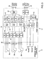
- FIG. 3 A simplified block diagram of a typical kinetic portion 12 and power conversion portion 14 electrical power generation subsystem is illustrated in Figure 3 .
- the fault tolerant architecture provides enhanced performance features as described herein.
- Each of the three windings 26a, 26b, 26c is electrically coupled to an associated converter module 38a, 38b, 38c. With each coupled pair of a winding and converter module being electrically and physically isolated from the other coupled pairs.
- power generated in the kinetic portion 12 flows through phase 1 conductor 28, phase 2 conductor 30 and phase 3 conductor 32.
- switch 40 When switch 40 is closed, the current flows through forward rectifier 42 to input filter 44 where a DC voltage is established to operate the converter 46.
- the DC voltage is used to provide power to the input filter 44 and buck-boost converter 46 where it is converted to the desired output voltage form. Through these steps, power is converted to the desired output form and each phase remains electrically and physically isolated. The three phases are then electrically and physically combined in output filter 48 to exit via DC power 34 feeder cable.
- the desired DC output voltage is 28 volt DC, 48 volt DC and/or 270 volt DC.
- the power conversion portion 14 provides regulated DC output power 34 and is capable of operation even in the presence of one or more faults.
- the power conversion portion includes a fault monitor function 50 that controls the rectifier switch 40 and a shorting circuit function 52. If a fault is detected in a feeder cable or in the power conversion unit 14, the rectifier switch 40 associated with that winding 26 is opened, stopping the flow of current through the faulty circuit. The generator system continues to provide power to the load (at a reduced capacity).
- the fault monitor 50 initiates a short within the shorting circuit 52 applying a current to one of the windings 26a, 26b, 26c. This produces a significant counter torque and the motive shaft associated with the faulty circuit is broken at a shear section. Sufficient counter torque is developed in this case utilizing just one of the windings 26 and one shorting circuit.
- the kinetic portion 12 output power is used to provide the energy required to develop the torque to break the shear neck shaft.
- the fault clearing method includes a motive shaft with a shear section. Temperature sensors 54 and fault detecting sensors may be positioned within the kinetic portion 12, the output 34 feeder cables and/or the power conversion portion 14. Some or all of the fault monitoring functions may be incorporated into the kinetic portion and some or all may be incorporated into the power conversion portion.
- a fault condition that requires mitigation is detected by the fault monitor and a low impedance "short" is applied to the windings 26.
- the “short” applied to the windings produces a counter torque sufficient to cause the motive shaft to break at the shear section.
- the “short” may be applied internal to the kinetic portion or externally (such as internal to the power conversion portion) and may be implemented with power semiconductors and associated control circuits or by electromechanical devices and associated control circuits.
- the "short” produces sufficient counter torque to break the shear section of the motive shaft at or above a defined speed threshold (typically at speeds of approximately 10% of the normal operating speed or greater in many PMM applications)
- FIG. 4 illustrates a motive shaft 18 during routine operation.
- the motive shaft 18 includes a shear section 56, such as a notch having a crack propagating apex 58. Proper selection of notch dimensions and apex angle enable tailoring the facture yield strength of the motive shaft.
- the prime mover (not shown) applies a torque 60 rotating the motive shaft 18.
- the shorting circuit causes a counter torque 62 to be applied to the motive shaft 18.
- the combination of torque 60 and counter torque 62 is sufficient to cause a crack 64 to propagate causing the motive shaft to break.
- electric power is not longer produced removing the hazard condition, but the prime mover continues to operate normally.
- PMM is significantly lighter and smaller than equivalent performance high reactance or fault tolerant configuration machine
- PMM is significantly more efficient and less costly to produce than the equivalent performance high reactance or fault tolerant configuration machine
- faults within the PMM are very effectively mitigated with this method (as well as external faults); and shut down of the prime mover is not required with this fault clearing method.
- This fault clearing method is compatible with fault tolerant system architectures such as described in US Patent Number 7,064,526 , including use of multiple isolated windings, use of redundancy in the PMA, PMG, PMSG and/or PCU functions.
- PCU may be designed so that a failure in one power converter will not propagate to or degrade the generator mode performance of other power converters.
- PMA, PMG, PMSG and PCU may be designed such that generator mode operation is achieved even in the event of a failure of up to "n-1" phases of an "n” phase PMA, PMG, PMSG and/or simultaneous failure of up to "n-1” phases of a PCU with "n” converter modules.
- PMA, PMG, PMSG and PCU may be designed such that each phase is electrically and physically isolated.
- PMA, PMG, PMSG and/or PCU may be designed to continuously monitor for and detect a ground fault condition within any phase of the PMA, PMG, PMSG and/or PCU; the ground fault detection function is fully testable, and thus a complete end-to-end functionality verification of the ground fault detection circuit can be performed.
- PCU may use multiple, parallel solid-state switching devices so that high performance and high reliability operation is achieved, as well as fault tolerant operability within each PCU converter.
- the PMA, PMG and/or PMSG can be configured as a bearingless machine using a gearbox integrated design, provided the drive shaft extension includes a shear neck design.
- the fault clearing and fault tolerant architecture applications include: aircraft and/or automotive applications requiring engine start operation and generation of DC electrical power; aircraft and/or automotive applications requiring engine start operation and generation of AC electrical power; and aircraft and/or automotive applications requiring engine start operation and generation of DC and AC electrical power.
- the PMM can be designed for operation as: integral assembly to engine shaft (i.e., PMM rotor rotates at same speed as main or auxiliary engine shaft; no bearings are required); shaft mounted, gearbox integrated assembly (i.e., PMM rotor is mounted directly to driveshaft on engine accessory gearbox (AGB); no bearings are required); and AGB mounted assembly (i.e., PMM rotor is typically mounted to a shaft and incorporates bearings so that the assembly interfaces to engine AGB in similar or identical fashion to conventional brushed starter/generators).
- integral assembly to engine shaft i.e., PMM rotor rotates at same speed as main or auxiliary engine shaft; no bearings are required
- shaft mounted, gearbox integrated assembly i.e., PMM rotor is mounted directly to driveshaft on engine accessory gearbox (AGB); no bearings are required
- AGB mounted assembly i.e., PMM rotor is typically mounted to a shaft and incorporates bearings so that the assembly interfaces to engine AGB in similar
- An optional switch or contactor can be added in series with the PMM stator winding to remove power from the feeder cables and/or PCU input.
- the use of this switch/contactor is optional with the "fault tolerant" architecture.
- PCU can be designed for operation as: single assembly located adjacent to or remote from PMM; multiple assemblies located adjacent to or remote from PMM; PCU/PMM is interconnected via low current feeder cable (i.e., PMM voltage is greater than average bus voltage); and PCU/PMM is interconnected via high current feeder cable (i.e., PMM voltage is equal or less than average bus voltage).
Landscapes
- Engineering & Computer Science (AREA)
- Power Engineering (AREA)
- General Engineering & Computer Science (AREA)
- Mechanical Engineering (AREA)
- Control Of Eletrric Generators (AREA)
Applications Claiming Priority (3)
| Application Number | Priority Date | Filing Date | Title |
|---|---|---|---|
| US6951208P | 2008-03-14 | 2008-03-14 | |
| US12/380,326 US7880448B2 (en) | 2008-03-14 | 2009-02-26 | Fault clearing method for permanent magnet machines |
| EP20090003220 EP2104224B1 (fr) | 2008-03-14 | 2009-03-05 | Procédé d'élimination de défauts pour machines à aimant permanent |
Related Parent Applications (2)
| Application Number | Title | Priority Date | Filing Date |
|---|---|---|---|
| EP09003220.2 Division | 2009-03-05 | ||
| EP20090003220 Division EP2104224B1 (fr) | 2008-03-14 | 2009-03-05 | Procédé d'élimination de défauts pour machines à aimant permanent |
Publications (2)
| Publication Number | Publication Date |
|---|---|
| EP2562926A1 true EP2562926A1 (fr) | 2013-02-27 |
| EP2562926B1 EP2562926B1 (fr) | 2014-01-29 |
Family
ID=41062308
Family Applications (2)
| Application Number | Title | Priority Date | Filing Date |
|---|---|---|---|
| EP12193638A Withdrawn EP2562925A1 (fr) | 2008-03-14 | 2009-03-05 | Procédé d'élimination de défauts pour machines à aimants permanents |
| EP12193644.7A Not-in-force EP2562926B1 (fr) | 2008-03-14 | 2009-03-05 | Procédé d'élimination de défauts pour machines à aimants permanents |
Family Applications Before (1)
| Application Number | Title | Priority Date | Filing Date |
|---|---|---|---|
| EP12193638A Withdrawn EP2562925A1 (fr) | 2008-03-14 | 2009-03-05 | Procédé d'élimination de défauts pour machines à aimants permanents |
Country Status (3)
| Country | Link |
|---|---|
| US (3) | US7880448B2 (fr) |
| EP (2) | EP2562925A1 (fr) |
| CA (2) | CA2790803A1 (fr) |
Families Citing this family (11)
| Publication number | Priority date | Publication date | Assignee | Title |
|---|---|---|---|---|
| US7880448B2 (en) * | 2008-03-14 | 2011-02-01 | Astronics Advanced Electronic Systems Corp. | Fault clearing method for permanent magnet machines |
| US8723489B2 (en) * | 2009-05-28 | 2014-05-13 | Deeya Energy, Inc. | Bi-directional buck-boost circuit |
| US8305021B2 (en) * | 2009-12-15 | 2012-11-06 | Astronics Advanced Electronic Systems Corp. | Dual purpose permanent magnet speed sensor and generator |
| EP2524423A1 (fr) * | 2010-01-13 | 2012-11-21 | Brusa Elektronik AG | Dispositif de commande et procédé de commande d'un enroulement rotorique excité séparément d'une machine synchrone |
| JP2014508498A (ja) | 2011-03-11 | 2014-04-03 | ブルサ エレクトロニック アーゲー | スイッチング素子付き励磁回路を備える同期機 |
| US9257889B2 (en) * | 2013-03-15 | 2016-02-09 | Hamilton Sundstrand Corporation | EPGS architecture with multi-channel synchronous generator and common field regulated exciter |
| US8928293B1 (en) * | 2013-08-02 | 2015-01-06 | Hamilton Sundstrand Corporation | Systems for wound field synchronous machines with zero speed rotor position detection during start for motoring and improved transient response for generation |
| CA2932102C (fr) | 2015-06-10 | 2024-04-30 | Rolls-Royce Corporation | Identification de defaillance et isolement dans un systeme de propulsion electrique |
| US11028812B2 (en) | 2016-07-27 | 2021-06-08 | Astronics Advanced Electronic Systems Corp. | Integrated brushless starter generator |
| US12328086B2 (en) * | 2022-05-27 | 2025-06-10 | Rolls-Royce Corporation | Aircraft with engine-driven permanent magnet generator |
| FR3145656A1 (fr) * | 2023-02-07 | 2024-08-09 | Safran Electrical & Power | Procédé de surveillance et de protection d’un système d’hybridation électrique contre le risque de feu |
Citations (4)
| Publication number | Priority date | Publication date | Assignee | Title |
|---|---|---|---|---|
| FR1521603A (fr) * | 1967-03-09 | 1968-04-19 | Snecma | Perfectionnements aux dispositifs limiteurs de couples |
| US20060087123A1 (en) * | 2004-10-22 | 2006-04-27 | Stout David E | Dual-rotor, single input/output starter-generator |
| US7064526B2 (en) | 2004-04-23 | 2006-06-20 | Astronics Advanced Electronic Systems Corp. | Fault tolerant architecture for permanent magnet starter generator subsystem |
| WO2007146246A2 (fr) * | 2006-06-14 | 2007-12-21 | Smiths Aerospace Llc | Démarreur/génératrice de moteur d'avion à double structure |
Family Cites Families (23)
| Publication number | Priority date | Publication date | Assignee | Title |
|---|---|---|---|---|
| US4045822A (en) * | 1976-05-03 | 1977-08-30 | Rca Corporation | Ground fault interrupter apparatus |
| US4695776A (en) * | 1985-12-23 | 1987-09-22 | Sunstrand Corporation | Power converter for an electrically-compensated constant speed drive |
| US4956563A (en) * | 1987-11-09 | 1990-09-11 | Perma Power Electronics, Inc. | Standby power supply |
| US4868406A (en) * | 1988-07-05 | 1989-09-19 | Sundstrand Corporation | Electrically compensated constant speed drive with prime mover start capability |
| US5493200A (en) | 1993-05-12 | 1996-02-20 | Sundstrand Corporation | Control for a brushless generator |
| US5594322A (en) | 1993-05-12 | 1997-01-14 | Sundstrand Corporation | Starter/generator system with variable-frequency exciter control |
| US5512811A (en) * | 1994-01-21 | 1996-04-30 | Sundstrand Corporation | Starter/generator system having multivoltage generation capability |
| US5929537A (en) | 1997-06-30 | 1999-07-27 | Sundstrand Corporation | PMG main engine starter/generator system |
| AU1786901A (en) * | 1999-11-24 | 2001-06-04 | Allied-Signal Inc. | Integrated fault protection for switched electronic systems for satellite applications |
| JP2001161032A (ja) * | 1999-12-01 | 2001-06-12 | Canon Inc | 系統連系パワーコンディショナ及びそれを用いた発電システム |
| US6700214B2 (en) * | 2000-02-14 | 2004-03-02 | Aura Systems, Inc. | Mobile power generation system |
| US6787933B2 (en) * | 2001-01-10 | 2004-09-07 | Capstone Turbine Corporation | Power generation system having transient ride-through/load-leveling capabilities |
| US6844707B1 (en) * | 2003-12-30 | 2005-01-18 | Pacific Scientific/Electro Kinetics Division | AC/DC brushless starter-generator |
| EP1847010A1 (fr) * | 2005-02-02 | 2007-10-24 | Magnetic Applications Inc. | Generateur d'impulsions pour un redresseur controle |
| US7276871B2 (en) * | 2005-07-25 | 2007-10-02 | Honeywell International, Inc. | System and method for fault protection for permanent magnet machines |
| US7388311B2 (en) | 2005-09-14 | 2008-06-17 | Ashman Technologies | Redundant windings with current limiting means for electric machines |
| US7372174B2 (en) * | 2005-11-11 | 2008-05-13 | Converteam Ltd | Power converters |
| US7511385B2 (en) * | 2005-11-11 | 2009-03-31 | Converteam Ltd | Power converters |
| JP4438786B2 (ja) * | 2005-11-17 | 2010-03-24 | セイコーエプソン株式会社 | Mems振動子及びその製造方法 |
| US7629699B2 (en) * | 2006-01-06 | 2009-12-08 | Aerodyne Research, Inc. | System and method for controlling a power generating system |
| RU2383451C1 (ru) * | 2006-01-17 | 2010-03-10 | Абб Швайц Аг | Топливно-электрическая система привода |
| US7880448B2 (en) * | 2008-03-14 | 2011-02-01 | Astronics Advanced Electronic Systems Corp. | Fault clearing method for permanent magnet machines |
| US7646178B1 (en) * | 2009-05-08 | 2010-01-12 | Fradella Richard B | Broad-speed-range generator |
-
2009
- 2009-02-26 US US12/380,326 patent/US7880448B2/en active Active
- 2009-03-05 CA CA2790803A patent/CA2790803A1/fr not_active Abandoned
- 2009-03-05 CA CA2657070A patent/CA2657070C/fr not_active Expired - Fee Related
- 2009-03-05 EP EP12193638A patent/EP2562925A1/fr not_active Withdrawn
- 2009-03-05 EP EP12193644.7A patent/EP2562926B1/fr not_active Not-in-force
-
2010
- 2010-12-23 US US12/977,281 patent/US8035357B2/en active Active
-
2011
- 2011-08-03 US US13/197,232 patent/US20110286133A1/en not_active Abandoned
Patent Citations (5)
| Publication number | Priority date | Publication date | Assignee | Title |
|---|---|---|---|---|
| FR1521603A (fr) * | 1967-03-09 | 1968-04-19 | Snecma | Perfectionnements aux dispositifs limiteurs de couples |
| US7064526B2 (en) | 2004-04-23 | 2006-06-20 | Astronics Advanced Electronic Systems Corp. | Fault tolerant architecture for permanent magnet starter generator subsystem |
| US7365521B2 (en) | 2004-04-23 | 2008-04-29 | Astronics Advanced Electronic Systems Corp. | Fault tolerant architecture for permanent magnet starter generator subsystem |
| US20060087123A1 (en) * | 2004-10-22 | 2006-04-27 | Stout David E | Dual-rotor, single input/output starter-generator |
| WO2007146246A2 (fr) * | 2006-06-14 | 2007-12-21 | Smiths Aerospace Llc | Démarreur/génératrice de moteur d'avion à double structure |
Also Published As
| Publication number | Publication date |
|---|---|
| CA2790803A1 (fr) | 2009-09-14 |
| CA2657070A1 (fr) | 2009-09-14 |
| US20090230927A1 (en) | 2009-09-17 |
| CA2657070C (fr) | 2013-07-23 |
| EP2562926B1 (fr) | 2014-01-29 |
| EP2562925A1 (fr) | 2013-02-27 |
| US20110149445A1 (en) | 2011-06-23 |
| US8035357B2 (en) | 2011-10-11 |
| US20110286133A1 (en) | 2011-11-24 |
| US7880448B2 (en) | 2011-02-01 |
Similar Documents
| Publication | Publication Date | Title |
|---|---|---|
| CA2657070C (fr) | Methode de suppression des anomalies des machines a aimant permanent | |
| US7064526B2 (en) | Fault tolerant architecture for permanent magnet starter generator subsystem | |
| US9425670B2 (en) | Reversible electrical machine for an aircraft | |
| JP6316281B2 (ja) | ヘリコプタタービンエンジン用制御・電力供給システム | |
| US10584671B2 (en) | Brushless starter generator | |
| EP2808996B1 (fr) | Liaison à courant continu commandé en tension d'excitation de générateur de fréquence variable | |
| US20110080000A1 (en) | Synchronous electrical machine | |
| US8040113B2 (en) | Fault tolerant generator or starter/generator with low torque ripple | |
| Besnard et al. | Electrical rotating machines and power electronics for new aircraft equipment systems | |
| JP7794426B2 (ja) | 発電機、モータ及び航空機 | |
| WO2023013398A1 (fr) | Système de production d'énergie et aéronef | |
| EP2045910B1 (fr) | Système démarreur/générateur avec contrôle pour le traitement d'une augmentation de la tension | |
| US20230257127A1 (en) | Coordinated fault response in rectifiers of hybrid aircraft | |
| EP2104224B1 (fr) | Procédé d'élimination de défauts pour machines à aimant permanent | |
| US20250183766A1 (en) | Stator control system | |
| US11840148B2 (en) | Hybrid aircraft having rectifier with integrated protection | |
| US12095405B2 (en) | Fault tolerant turbo-generator system | |
| US12081015B2 (en) | Permanent magnet machine fault protection | |
| US20250309728A1 (en) | Method and system for rapid starting of a combustion engine in a multi-engine aircraft | |
| CN110578604A (zh) | 一种电气设备 |
Legal Events
| Date | Code | Title | Description |
|---|---|---|---|
| PUAI | Public reference made under article 153(3) epc to a published international application that has entered the european phase |
Free format text: ORIGINAL CODE: 0009012 |
|
| AC | Divisional application: reference to earlier application |
Ref document number: 2104224 Country of ref document: EP Kind code of ref document: P |
|
| AK | Designated contracting states |
Kind code of ref document: A1 Designated state(s): AT BE BG CH CY CZ DE DK EE ES FI FR GB GR HR HU IE IS IT LI LT LU LV MC MK MT NL NO PL PT RO SE SI SK TR |
|
| 17P | Request for examination filed |
Effective date: 20130613 |
|
| RBV | Designated contracting states (corrected) |
Designated state(s): AT BE BG CH CY CZ DE DK EE ES FI FR GB GR HR HU IE IS IT LI LT LU LV MC MK MT NL NO PL PT RO SE SI SK TR |
|
| REG | Reference to a national code |
Ref country code: DE Ref legal event code: R079 Ref document number: 602009021749 Country of ref document: DE Free format text: PREVIOUS MAIN CLASS: H02P0009020000 Ipc: B64D0045000000 |
|
| RIC1 | Information provided on ipc code assigned before grant |
Ipc: H02P 9/02 20060101ALI20130725BHEP Ipc: H02P 9/00 20060101ALI20130725BHEP Ipc: F16D 9/08 20060101ALI20130725BHEP Ipc: B64D 45/00 20060101AFI20130725BHEP |
|
| GRAP | Despatch of communication of intention to grant a patent |
Free format text: ORIGINAL CODE: EPIDOSNIGR1 |
|
| INTG | Intention to grant announced |
Effective date: 20130912 |
|
| GRAS | Grant fee paid |
Free format text: ORIGINAL CODE: EPIDOSNIGR3 |
|
| GRAA | (expected) grant |
Free format text: ORIGINAL CODE: 0009210 |
|
| AC | Divisional application: reference to earlier application |
Ref document number: 2104224 Country of ref document: EP Kind code of ref document: P |
|
| AK | Designated contracting states |
Kind code of ref document: B1 Designated state(s): AT BE BG CH CY CZ DE DK EE ES FI FR GB GR HR HU IE IS IT LI LT LU LV MC MK MT NL NO PL PT RO SE SI SK TR |
|
| REG | Reference to a national code |
Ref country code: GB Ref legal event code: FG4D |
|
| REG | Reference to a national code |
Ref country code: CH Ref legal event code: EP |
|
| REG | Reference to a national code |
Ref country code: AT Ref legal event code: REF Ref document number: 651447 Country of ref document: AT Kind code of ref document: T Effective date: 20140215 |
|
| RAP2 | Party data changed (patent owner data changed or rights of a patent transferred) |
Owner name: ASTRONICS ADVANCED ELECTRONIC SYSTEMS CORP. |
|
| REG | Reference to a national code |
Ref country code: IE Ref legal event code: FG4D |
|
| REG | Reference to a national code |
Ref country code: DE Ref legal event code: R096 Ref document number: 602009021749 Country of ref document: DE Effective date: 20140313 |
|
| REG | Reference to a national code |
Ref country code: AT Ref legal event code: MK05 Ref document number: 651447 Country of ref document: AT Kind code of ref document: T Effective date: 20140129 |
|
| REG | Reference to a national code |
Ref country code: NL Ref legal event code: VDEP Effective date: 20140129 |
|
| REG | Reference to a national code |
Ref country code: LT Ref legal event code: MG4D |
|
| PG25 | Lapsed in a contracting state [announced via postgrant information from national office to epo] |
Ref country code: NO Free format text: LAPSE BECAUSE OF FAILURE TO SUBMIT A TRANSLATION OF THE DESCRIPTION OR TO PAY THE FEE WITHIN THE PRESCRIBED TIME-LIMIT Effective date: 20140429 Ref country code: IS Free format text: LAPSE BECAUSE OF FAILURE TO SUBMIT A TRANSLATION OF THE DESCRIPTION OR TO PAY THE FEE WITHIN THE PRESCRIBED TIME-LIMIT Effective date: 20140529 Ref country code: LT Free format text: LAPSE BECAUSE OF FAILURE TO SUBMIT A TRANSLATION OF THE DESCRIPTION OR TO PAY THE FEE WITHIN THE PRESCRIBED TIME-LIMIT Effective date: 20140129 |
|
| PG25 | Lapsed in a contracting state [announced via postgrant information from national office to epo] |
Ref country code: NL Free format text: LAPSE BECAUSE OF FAILURE TO SUBMIT A TRANSLATION OF THE DESCRIPTION OR TO PAY THE FEE WITHIN THE PRESCRIBED TIME-LIMIT Effective date: 20140129 Ref country code: FI Free format text: LAPSE BECAUSE OF FAILURE TO SUBMIT A TRANSLATION OF THE DESCRIPTION OR TO PAY THE FEE WITHIN THE PRESCRIBED TIME-LIMIT Effective date: 20140129 Ref country code: AT Free format text: LAPSE BECAUSE OF FAILURE TO SUBMIT A TRANSLATION OF THE DESCRIPTION OR TO PAY THE FEE WITHIN THE PRESCRIBED TIME-LIMIT Effective date: 20140129 Ref country code: CY Free format text: LAPSE BECAUSE OF FAILURE TO SUBMIT A TRANSLATION OF THE DESCRIPTION OR TO PAY THE FEE WITHIN THE PRESCRIBED TIME-LIMIT Effective date: 20140129 Ref country code: SE Free format text: LAPSE BECAUSE OF FAILURE TO SUBMIT A TRANSLATION OF THE DESCRIPTION OR TO PAY THE FEE WITHIN THE PRESCRIBED TIME-LIMIT Effective date: 20140129 Ref country code: ES Free format text: LAPSE BECAUSE OF FAILURE TO SUBMIT A TRANSLATION OF THE DESCRIPTION OR TO PAY THE FEE WITHIN THE PRESCRIBED TIME-LIMIT Effective date: 20140129 Ref country code: PT Free format text: LAPSE BECAUSE OF FAILURE TO SUBMIT A TRANSLATION OF THE DESCRIPTION OR TO PAY THE FEE WITHIN THE PRESCRIBED TIME-LIMIT Effective date: 20140529 |
|
| PG25 | Lapsed in a contracting state [announced via postgrant information from national office to epo] |
Ref country code: HR Free format text: LAPSE BECAUSE OF FAILURE TO SUBMIT A TRANSLATION OF THE DESCRIPTION OR TO PAY THE FEE WITHIN THE PRESCRIBED TIME-LIMIT Effective date: 20140129 Ref country code: LV Free format text: LAPSE BECAUSE OF FAILURE TO SUBMIT A TRANSLATION OF THE DESCRIPTION OR TO PAY THE FEE WITHIN THE PRESCRIBED TIME-LIMIT Effective date: 20140129 Ref country code: BE Free format text: LAPSE BECAUSE OF FAILURE TO SUBMIT A TRANSLATION OF THE DESCRIPTION OR TO PAY THE FEE WITHIN THE PRESCRIBED TIME-LIMIT Effective date: 20140129 |
|
| REG | Reference to a national code |
Ref country code: DE Ref legal event code: R097 Ref document number: 602009021749 Country of ref document: DE |
|
| PG25 | Lapsed in a contracting state [announced via postgrant information from national office to epo] |
Ref country code: RO Free format text: LAPSE BECAUSE OF FAILURE TO SUBMIT A TRANSLATION OF THE DESCRIPTION OR TO PAY THE FEE WITHIN THE PRESCRIBED TIME-LIMIT Effective date: 20140129 Ref country code: EE Free format text: LAPSE BECAUSE OF FAILURE TO SUBMIT A TRANSLATION OF THE DESCRIPTION OR TO PAY THE FEE WITHIN THE PRESCRIBED TIME-LIMIT Effective date: 20140129 Ref country code: LU Free format text: LAPSE BECAUSE OF FAILURE TO SUBMIT A TRANSLATION OF THE DESCRIPTION OR TO PAY THE FEE WITHIN THE PRESCRIBED TIME-LIMIT Effective date: 20140305 Ref country code: DK Free format text: LAPSE BECAUSE OF FAILURE TO SUBMIT A TRANSLATION OF THE DESCRIPTION OR TO PAY THE FEE WITHIN THE PRESCRIBED TIME-LIMIT Effective date: 20140129 Ref country code: CZ Free format text: LAPSE BECAUSE OF FAILURE TO SUBMIT A TRANSLATION OF THE DESCRIPTION OR TO PAY THE FEE WITHIN THE PRESCRIBED TIME-LIMIT Effective date: 20140129 |
|
| REG | Reference to a national code |
Ref country code: CH Ref legal event code: PL |
|
| PG25 | Lapsed in a contracting state [announced via postgrant information from national office to epo] |
Ref country code: PL Free format text: LAPSE BECAUSE OF FAILURE TO SUBMIT A TRANSLATION OF THE DESCRIPTION OR TO PAY THE FEE WITHIN THE PRESCRIBED TIME-LIMIT Effective date: 20140129 Ref country code: SK Free format text: LAPSE BECAUSE OF FAILURE TO SUBMIT A TRANSLATION OF THE DESCRIPTION OR TO PAY THE FEE WITHIN THE PRESCRIBED TIME-LIMIT Effective date: 20140129 |
|
| PLBE | No opposition filed within time limit |
Free format text: ORIGINAL CODE: 0009261 |
|
| STAA | Information on the status of an ep patent application or granted ep patent |
Free format text: STATUS: NO OPPOSITION FILED WITHIN TIME LIMIT |
|
| REG | Reference to a national code |
Ref country code: IE Ref legal event code: MM4A |
|
| 26N | No opposition filed |
Effective date: 20141030 |
|
| PG25 | Lapsed in a contracting state [announced via postgrant information from national office to epo] |
Ref country code: CH Free format text: LAPSE BECAUSE OF NON-PAYMENT OF DUE FEES Effective date: 20140331 Ref country code: LI Free format text: LAPSE BECAUSE OF NON-PAYMENT OF DUE FEES Effective date: 20140331 Ref country code: IE Free format text: LAPSE BECAUSE OF NON-PAYMENT OF DUE FEES Effective date: 20140305 |
|
| REG | Reference to a national code |
Ref country code: DE Ref legal event code: R097 Ref document number: 602009021749 Country of ref document: DE Effective date: 20141030 |
|
| PG25 | Lapsed in a contracting state [announced via postgrant information from national office to epo] |
Ref country code: SI Free format text: LAPSE BECAUSE OF FAILURE TO SUBMIT A TRANSLATION OF THE DESCRIPTION OR TO PAY THE FEE WITHIN THE PRESCRIBED TIME-LIMIT Effective date: 20140129 |
|
| PG25 | Lapsed in a contracting state [announced via postgrant information from national office to epo] |
Ref country code: MT Free format text: LAPSE BECAUSE OF FAILURE TO SUBMIT A TRANSLATION OF THE DESCRIPTION OR TO PAY THE FEE WITHIN THE PRESCRIBED TIME-LIMIT Effective date: 20140129 |
|
| REG | Reference to a national code |
Ref country code: FR Ref legal event code: PLFP Year of fee payment: 8 |
|
| PG25 | Lapsed in a contracting state [announced via postgrant information from national office to epo] |
Ref country code: BG Free format text: LAPSE BECAUSE OF FAILURE TO SUBMIT A TRANSLATION OF THE DESCRIPTION OR TO PAY THE FEE WITHIN THE PRESCRIBED TIME-LIMIT Effective date: 20140129 Ref country code: MC Free format text: LAPSE BECAUSE OF FAILURE TO SUBMIT A TRANSLATION OF THE DESCRIPTION OR TO PAY THE FEE WITHIN THE PRESCRIBED TIME-LIMIT Effective date: 20140129 |
|
| PG25 | Lapsed in a contracting state [announced via postgrant information from national office to epo] |
Ref country code: IT Free format text: LAPSE BECAUSE OF FAILURE TO SUBMIT A TRANSLATION OF THE DESCRIPTION OR TO PAY THE FEE WITHIN THE PRESCRIBED TIME-LIMIT Effective date: 20140129 Ref country code: GR Free format text: LAPSE BECAUSE OF FAILURE TO SUBMIT A TRANSLATION OF THE DESCRIPTION OR TO PAY THE FEE WITHIN THE PRESCRIBED TIME-LIMIT Effective date: 20140430 |
|
| PG25 | Lapsed in a contracting state [announced via postgrant information from national office to epo] |
Ref country code: TR Free format text: LAPSE BECAUSE OF FAILURE TO SUBMIT A TRANSLATION OF THE DESCRIPTION OR TO PAY THE FEE WITHIN THE PRESCRIBED TIME-LIMIT Effective date: 20140129 Ref country code: HU Free format text: LAPSE BECAUSE OF FAILURE TO SUBMIT A TRANSLATION OF THE DESCRIPTION OR TO PAY THE FEE WITHIN THE PRESCRIBED TIME-LIMIT; INVALID AB INITIO Effective date: 20090305 |
|
| REG | Reference to a national code |
Ref country code: FR Ref legal event code: PLFP Year of fee payment: 9 |
|
| REG | Reference to a national code |
Ref country code: DE Ref legal event code: R082 Ref document number: 602009021749 Country of ref document: DE Representative=s name: SCHMITT-NILSON SCHRAUD WAIBEL WOHLFROM PATENTA, DE |
|
| REG | Reference to a national code |
Ref country code: FR Ref legal event code: PLFP Year of fee payment: 10 |
|
| PG25 | Lapsed in a contracting state [announced via postgrant information from national office to epo] |
Ref country code: MK Free format text: LAPSE BECAUSE OF FAILURE TO SUBMIT A TRANSLATION OF THE DESCRIPTION OR TO PAY THE FEE WITHIN THE PRESCRIBED TIME-LIMIT Effective date: 20140129 |
|
| PGFP | Annual fee paid to national office [announced via postgrant information from national office to epo] |
Ref country code: DE Payment date: 20200327 Year of fee payment: 12 Ref country code: GB Payment date: 20200327 Year of fee payment: 12 |
|
| PGFP | Annual fee paid to national office [announced via postgrant information from national office to epo] |
Ref country code: FR Payment date: 20200325 Year of fee payment: 12 |
|
| REG | Reference to a national code |
Ref country code: DE Ref legal event code: R119 Ref document number: 602009021749 Country of ref document: DE |
|
| GBPC | Gb: european patent ceased through non-payment of renewal fee |
Effective date: 20210305 |
|
| PG25 | Lapsed in a contracting state [announced via postgrant information from national office to epo] |
Ref country code: DE Free format text: LAPSE BECAUSE OF NON-PAYMENT OF DUE FEES Effective date: 20211001 Ref country code: GB Free format text: LAPSE BECAUSE OF NON-PAYMENT OF DUE FEES Effective date: 20210305 Ref country code: FR Free format text: LAPSE BECAUSE OF NON-PAYMENT OF DUE FEES Effective date: 20210331 |