EP2562963B1 - Eingebettete end-to-end-verzögerungsinformation für datennetzwerke - Google Patents
Eingebettete end-to-end-verzögerungsinformation für datennetzwerke Download PDFInfo
- Publication number
- EP2562963B1 EP2562963B1 EP12181268.9A EP12181268A EP2562963B1 EP 2562963 B1 EP2562963 B1 EP 2562963B1 EP 12181268 A EP12181268 A EP 12181268A EP 2562963 B1 EP2562963 B1 EP 2562963B1
- Authority
- EP
- European Patent Office
- Prior art keywords
- delay
- value
- virtual link
- nodes
- corresponding frame
- Prior art date
- Legal status (The legal status is an assumption and is not a legal conclusion. Google has not performed a legal analysis and makes no representation as to the accuracy of the status listed.)
- Active
Links
Images
Classifications
-
- H—ELECTRICITY
- H04—ELECTRIC COMMUNICATION TECHNIQUE
- H04L—TRANSMISSION OF DIGITAL INFORMATION, e.g. TELEGRAPHIC COMMUNICATION
- H04L43/00—Arrangements for monitoring or testing data switching networks
- H04L43/10—Active monitoring, e.g. heartbeat, ping or trace-route
- H04L43/106—Active monitoring, e.g. heartbeat, ping or trace-route using time related information in packets, e.g. by adding timestamps
-
- H—ELECTRICITY
- H04—ELECTRIC COMMUNICATION TECHNIQUE
- H04L—TRANSMISSION OF DIGITAL INFORMATION, e.g. TELEGRAPHIC COMMUNICATION
- H04L43/00—Arrangements for monitoring or testing data switching networks
- H04L43/08—Monitoring or testing based on specific metrics, e.g. QoS, energy consumption or environmental parameters
- H04L43/0852—Delays
- H04L43/0858—One way delays
Definitions
- ARINC 664 part 7 defines a profiled Ethernet that allows analyzing traffic flows between endpoints of a full-duplex switched Ethernet network with respect to transmission timing.
- a virtual link is realized by a locally administered multicast group with a network-wide unique multicast Ethernet address. That is all frames of a virtual link use the same Ethernet multicast destination address, whereas frames of different virtual links use different Ethernet multicast destination addresses.
- frames of a virtual link can thus be identified by their destination Ethernet addresses.
- the present invention provides a system as defined in claim 1.
- the system may include the features of any one or more of dependent claims 2 to 5.
- the present invention also provides a method as defined in claim 6.
- the method may include the features of any one or more of dependent claims 7 to 10.
- a system comprising a plurality of nodes, at least one of the plurality of nodes configured to insert, on a per-virtual link basis, a delay value into a dynamic delay field of a frame corresponding to the respective virtual link, wherein the dynamic delay value represents latency of frames of the respective virtual link.
- the system also comprises a switch having a plurality of ports, each port coupled to one of the plurality of nodes. The switch is configured to route frames received from the plurality of nodes to one or more of the plurality of nodes. At least one of the plurality of nodes is configured to store frames received from the switch in a buffer and to update the value in the dynamic delay field to reflect the end-to-end system delay.
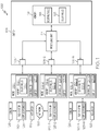
- FIG. 1 is a block diagram of one embodiment of an exemplary system 100.
- the system 100 includes a plurality of nodes 102-1 ... 102-N (also referred to as end systems) and at least one switch 104.
- the system 100 is configured to use virtual links to communicate frames between nodes 102-1 ... 102-N via the switch 104.
- a virtual link is a unidirectional logic path connecting two or more nodes 102 via the switch 104.
- the system 100 is a full duplex switched Ethernet network configured to implement a protocol compatible with the Aeronautical Radio, Incorporated (ARINC) standard 664 part 7 (also referred to as Avionics Full-Duplex Switched Ethernet (AFDX)).
- ARINC Aeronautical Radio, Incorporated
- AFDX Avionics Full-Duplex Switched Ethernet
- a virtual link is restricted to have one and only one source node 102 as defined in the ARINC standard 664 part 7.
- the switch 104 is configured to accept a plurality of nodes 102 as valid source nodes for a single virtual link as described in the '046 application.
- Each node 102 is communicatively coupled to a respective sub-system 120.
- the implementation of each sub-system 120 is dependent on the implementation of system 100.
- the system 100 is implemented as an avionics system in this example.
- each of sub-systems 120 are implemented as one of, but not limited to, a flight computer system, a navigation system, a Global Navigation Satellite System (GNSS), etc. Therefore, sub-systems 120-1 and 120-N are each coupled to one or more sensors 126 and one or more actuators 128 corresponding to the respective implementations of sub-systems 120-1 and 120-N.
- sub-system 120-2 is implemented, in this embodiment, as a gateway coupled to another network 130, such as the internet.
- Each sub-system 120 provides data to the respective node 102.
- each sub-system 120 includes higher-level application(s) 125 implemented at the application layer.
- application layer is known to one of skill in the art and, as used herein, refers to programs and services which implement high-level functions to accomplish tasks over the network such as protocols which implement specific user applications.
- Each node 102 processes and outputs the data via one or more corresponding virtual links.
- each node 102 includes a respective controller or processing unit 124 that is configured to insert, on a per-virtual link basis, one or more delay values into a field of the corresponding Ethernet frame based on the corresponding delay rules 122 stored in a memory 132 of the respective node 102.
- the one or more delay values represent the delay or latency that the corresponding Ethernet frame experienced while residing in the node 102 or being transmitted from the node 102 to another device in the system 100.
- the delay values are dynamic values that are measured by the respective node 102, such as, but not limited to, the queuing delay of the frame in an output queue.
- the delay values are static values that are configured a priori and stored in the node 102, such as, but not limited to, the transport delay on the wire from a transmitting port of the node to a receiving port of another device in the system 100.
- the controller 124 is configured to determine which delay value or values to add to the corresponding frame on a per-virtual link basis based on the delay rules 122. For example, one or more static delay values can be selected based on the contents of the frame corresponding to the respective virtual link. That is, the static delay value or values can be selected based on one or more of the virtual link ID, the Internet Protocol (IP) source address, the IP destination address, the User Datagram Protocol (UDP) source port, the UDP destination port, or other fields contained in the Ethernet frame payload.
- IP Internet Protocol
- UDP User Datagram Protocol
- the controller 124 is also configured to update a checksum (also referred to as a Frame Check Sequence (FCS) or Cyclic Redundancy Checksum (CRC)) based on the inserted delay values.
- FCS Frame Check Sequence
- CRC Cyclic Redundancy Checksum
- the checksum can reside in a different frame from the inserted delay values, in some embodiments, such as in embodiments implementing fragmented frame packets.
- the delay values are only added to specific frames of a virtual link, such as the first fragment of a fragmented UDP packet, in some embodiments, based on the delay rules 122.
- the nodes 102 After inserting the delay values and performing other processing on the frames, such as policing to ensure that the virtual links comply with a bandwidth allocation gap (BAG) requirement, the nodes 102 transmit the respective frames of the virtual links to the switch 104.
- the switch 104 receives the frames over a corresponding port 106-1 ... 106-N.
- the switch 104 processes each received frame in processing unit 114.
- the processing unit 114 is configured to determine if a frame was received on a valid port for the corresponding virtual link of the frame.
- the processing unit 114 routes the validly received frames to one or more of the ports 106-1 ... 106-N to be output to one or more nodes 102-1 ... 102-N.
- the processing unit 114 is configured to insert one or more delay values into a field of the received frames (also referred to as a delay field) on a per-virtual link basis based on the delay rules 123 stored in the memory 116.
- the delay value to be inserted into a given frame is determined based on the port 106 over which the frame was received, in some embodiments.
- the processing unit 104 is configured to insert delay values into frames corresponding to some virtual links, but not the frames corresponding to all virtual links.
- the delay values that are inserted into a frame represent a range of values, in some embodiments, rather than a specific value.
- the processing unit 114 includes or functions with software programs, firmware or other computer readable instructions for carrying out various methods, process tasks, calculations, and control functions, used in the insertion of delay values into a field of the Ethernet frame on a per-virtual link basis. These instructions are typically stored on any appropriate computer readable medium used for storage of computer readable instructions or data structures.
- the computer readable medium can be implemented as any available media that can be accessed by a general purpose or special purpose computer or processor, or any programmable logic device. Suitable processor-readable media may include storage or memory media such as magnetic or optical media.
- storage or memory media may include conventional hard disks, Compact Disk - Read Only Memory (CD-ROM), volatile or non-volatile media such as Random Access Memory (RAM) (including, but not limited to, Synchronous Dynamic Random Access Memory (SDRAM), Double Data Rate (DDR) RAM, RAMBUS Dynamic RAM (RDRAM), Static RAM (SRAM), etc.), Read Only Memory (ROM), Electrically Erasable Programmable ROM (EEPROM), and flash memory, etc.
- RAM Random Access Memory
- SDRAM Synchronous Dynamic Random Access Memory
- DDR Double Data Rate
- RDRAM RAMBUS Dynamic RAM
- SRAM Static RAM
- ROM Read Only Memory
- EEPROM Electrically Erasable Programmable ROM
- flash memory etc.
- Suitable processor-readable media may also include transmission media such as electrical, electromagnetic, or digital signals, conveyed via a communication medium such as a network and/or a wireless link.
- the processing unit 104 in the switch routes the received frames to the nodes 102 based on the routing table 118, as discussed above. Received frames are placed in a buffer 127 at the respective node until accessed by a higher-level application 125 in the corresponding sub-system 120.
- the receiving node 102 inserts a dynamic time stamp into the delay filed at the physical layer.
- the term "physical layer” is known to one of skill in the art and, as used herein, refers to physical hardware components of the system such as, but not limited to, transmission media, pins, network adapters, host bus adapters, circuit elements, etc.
- dynamic time stamp is used herein to refer to a time stamp that is updated to reflect changes in the delay time.
- the controller 124 inserts a time stamp into the dynamic delay field, using components in the physical layer, when the corresponding message is placed into a buffer 127.
- the processing unit updates the timestamp, such as upon the occurrence of other events.
- the timestamp in the dynamic delay field can be updated at specific intervals or upon access to the message by an application/service 125 operating in the application layer.
- the controller 124 updates the value in the dynamic delay field.
- the dynamic delay field is continually updated to provide, to the application 125 residing at the application layer, a real-time end-to-end system delay.
- the real-time end-to-end system delay is the delay relative to the source from the time of sending the message to the time the message is accessed.
- static values can be initially inserted into the delay field by the corresponding node 102, as described above, the static values are updated to reflect the real-time delay.
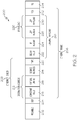
- FIG. 2 is a block diagram representing an exemplary frame 200 communicated between the nodes 102 and switch 104.
- the frame 200 includes a preamble 202, a start of frame (SOF) 204, and an interframe gap (IFG) 234 as known to one of skill in the art.
- the frame 200 includes an Ethernet Frame 206.
- the Ethernet frame comprises a header 208 and a payload 210.
- the Ethernet header 208 is comprised of a destination address 212 and a source address 214.
- the destination address 212 is comprised of a constant field 216 and a virtual link ID 218.
- the virtual link ID is used to route the frame in the switch using the routing table that indicates to which output ports the virtual link is associated.
- the Ethernet header 208 also includes a type field 220 as known to one of skill in the art.
- the Ethernet payload 210 includes a delay field 222, an IP header 224, and an IP payload 226.
- the nodes 102 and/or switch 104 are configured to insert delay values into the delay field 222 as described above.
- the position of the delay field 222 in the Ethernet payload 210 of Figure 2 is provided by way of example and not by way of limitation.
- the position and/or length of the delay field 222 can be determined dynamically as the frame passes through the device by checking the contents of the frame against rules (e.g. delay rules 122) stored in the nodes 102 or switch 104.
- the stored rules indicate, in some implementations, which delay values to insert based on one or more of the virtual link ID, the IP addresses or the UDP port numbers. Thus, it is determined individually per virtual link ID, whether to insert a static delay value, a dynamic delay value, or a combination of static and dynamic delay values, as well as, the values or range of values to be inserted into the delay field 222.
- the IP payload 226, in this example, is comprised of a UDP header 228 and a UDP payload 230 as known to one of skill in the art.
- the Ethernet frame 206 includes a Frame Check Sequence 232.
- the FCS 232 is updated to reflect the delay values inserted into the delay field 222.
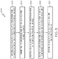
- FIG. 3 is a flow chart depicting one embodiment of a method 300 of communicating frames in a system such as system 100 described above.
- a delay value is inserted into a delay field of a corresponding frame of a respective virtual link at a source node on a per-virtual link basis, as described above.
- the delay value represents latency of frames of the respective virtual link.
- a source node is a node that is designated as the source of a frame for a respective virtual link.
- a destination node as used herein, is a node for the respective virtual link that is designated as a node to which the frame from the corresponding source node is routed.
- Inserting a delay value into a delay field includes, in some embodiments, inserting at least one of a dynamic delay value and a static delay value, as described above. In addition, in some embodiments, inserting the delay value includes updating a checksum in the corresponding frame based on the inserted delay value, as described above.
- the corresponding frame having the delay field is transmitted from the source node to a switch.
- the switch is configured to insert a delay value into the delay field, as described above, at block 306.
- inserting a delay value can include adding a static value, dynamic value, or combination of static and dynamic values to the received value contained in the delay field and replacing the received value with the result of adding values to the received value.
- inserting the delay value includes updating any checksums that are affected by the inserted delay value.
- the switch does not insert a delay value.
- the corresponding frame is routed to one or more destination nodes based on the respective virtual link. In this embodiment, the frames are transmitted and routed using a protocol compatible with the ARINC 664 part 7 standard. However, it is to be understood that other protocols can be used in other embodiments.
- the value in the delay field is updated to reflect the real-time end-to-end system delay.
- the delay field can be updated upon the occurrence of specific events, such as access of the frame by an application in the application layer, as discussed above.
Landscapes
- Engineering & Computer Science (AREA)
- Computer Networks & Wireless Communication (AREA)
- Signal Processing (AREA)
- Health & Medical Sciences (AREA)
- Cardiology (AREA)
- General Health & Medical Sciences (AREA)
- Environmental & Geological Engineering (AREA)
- Data Exchanges In Wide-Area Networks (AREA)
Claims (10)
- System (100), umfassend:eine Vielzahl von Knoten (102-1 ... 102-N), wobei mindestens einer der Vielzahl von Knoten konfiguriert ist, einen Verzögerungswert auf einer Basis pro virtuelle Verknüpfung in ein Feld für dynamische Verzögerung eines Rahmens korrespondierend mit der jeweiligen virtuellen Verknüpfung einzufügen, wobei der Wert der dynamischen Verzögerung eine Latenz von Rahmen der jeweiligen virtuellen Verknüpfung repräsentiert; undeine Vermittlungseinrichtung (104) mit einer Vielzahl von Anschlüssen (106-1 ... 106-N), wobei jeder Anschluss an einen der Vielzahl von Knoten (102-1 ... 102-N) gekoppelt ist;wobei die Vermittlungseinrichtung (104) konfiguriert ist, von der Vielzahl von Knoten (102-1 ... 102-N) empfangene Rahmen zu einem oder mehreren der Vielzahl von Knoten (102-1 ... 102-N) zu leiten; undwobei mindestens einer der Vielzahl von Knoten (102-1 ... 102-N) konfiguriert ist, von der Vermittlungseinrichtung (104) empfangene Rahmen in einem Zwischenspeicher (127) zu speichern und den Wert in dem Feld für dynamische Verzögerung zu aktualisieren, um die Systemverzögerung von Ende zu Ende zu reflektieren;dadurch gekennzeichnet, dass mindestens einer der zum Einfügen eines Verzögerungswerts konfigurierten Knoten konfiguriert ist, eine Kombination von statischen und dynamischen Verzögerungswerten auf einer Basis pro virtuelle Verknüpfung einzufügen;wobei ein dynamischer Verzögerungswert ein Wert ist, der durch den jeweiligen mindestens einen der Vielzahl von Knoten gemessen wird, und ein statischer Verzögerungswert ein Wert ist, der a priori konfiguriert und in dem jeweiligen mindestens einen der Vielzahl von Knoten gespeichert ist, z. B. die Transportverzögerung des Drahts von einem Übertragungsanschluss des Knotens zu dem Empfangsanschluss einer anderen Vorrichtung in dem System.
- System (100) nach Anspruch 1, wobei der mindestens eine zum Aktualisieren des Werts in dem Feld für dynamische Verzögerung konfigurierte Knoten konfiguriert ist, das Feld für dynamische Verzögerung zu aktualisieren, wenn durch eine Anwendung auf den Rahmen zugegriffen wird.
- System (100) nach Anspruch 1, wobei der mindestens eine Knoten konfiguriert ist, den einzufügenden Verzögerungswert basierend auf einem oder mehreren einer ID einer virtuellen Verknüpfung des korrespondierenden Rahmens, einer Internetprotokoll- bzw. IP-Ausgangsadresse des korrespondierenden Rahmens, einer IP-Bestimmungsadresse des korrespondierenden Rahmens, eines Benutzerdatagrammprotokoll- bzw. UDP-Ausgangsanschlusses des korrespondierenden Rahmens und eines UDP-Bestimmungsanschlusses des korrespondierenden Rahmens zu bestimmen.
- System (100) nach Anspruch 1, wobei der mindestens eine Knoten konfiguriert ist, den Verzögerungswert in eine Teilmenge sämtlicher der mit der jeweiligen virtuellen Verknüpfung korrespondierenden Rahmen einzufügen.
- System (100) nach Anspruch 1, wobei die Vermittlungseinrichtung (104) konfiguriert ist, einen Verzögerungswert in das Verzögerungsfeld des von dem mindestens einen Knoten empfangenen korrespondierenden Rahmens auf einer Basis pro virtuelle Verknüpfung einzufügen.
- Verfahren (300) zum Kommunizieren von Rahmen, das Verfahren umfassend:Einfügen eines Verzögerungswerts auf einer Basis pro virtuelle Verknüpfung in ein Verzögerungsfeld eines korrespondierenden Rahmens einer jeweiligen virtuellen Verknüpfung an einem Ausgangsknoten, wobei der Verzögerungswert eine Latenz von Rahmen der jeweiligen virtuellen Verknüpfung (302) repräsentiert;Übertragen des korrespondierenden Rahmens mit dem Verzögerungsfeld von dem Knoten an eine Vermittlungseinrichtung (304);Leiten des korrespondierenden Rahmens mit dem Verzögerungsfeld von der Vermittlungseinrichtung an einen oder mehrere Bestimmungsknoten basierend auf der jeweiligen virtuellen Verknüpfung (308); undAktualisieren des Werts in dem Verzögerungsfeld an dem einen oder den mehreren Bestimmungsknoten, um Echtzeit-Systemverzögerung von Ende zu Ende (310) zu reflektieren;dadurch gekennzeichnet, dass Einfügen eines Verzögerungswerts Einfügen einer Kombination von statischen und dynamischen Verzögerungswerten auf einer Basis pro virtuelle Verknüpfung umfasst;wobei ein dynamischer Verzögerungswert ein Wert ist, der durch den jeweiligen mindestens einen der Vielzahl von Knoten gemessen wird, und ein statischer Verzögerungswert ein Wert ist, der a priori konfiguriert und in dem jeweiligen mindestens einen der Vielzahl von Knoten gespeichert ist, z. B. die Transportverzögerung in dem Draht von einem Übertragungsanschluss des Knotens zu dem Empfangsanschluss einer anderen Vorrichtung in dem System.
- Verfahren (300) nach Anspruch 6, wobei Aktualisieren des Werts in dem Verzögerungsfeld umfasst, den Wert in dem Verzögerungsfeld zu aktualisieren, wenn durch eine Anwendung (310) auf den Rahmen zugegriffen wird.
- Verfahren (300) nach Anspruch 6, wobei Einfügen des Verzögerungswerts umfasst, eine Prüfsumme in dem korrespondierenden Rahmen basierend auf dem eingefügten Verzögerungswert (302) zu aktualisieren.
- Verfahren (300) nach Anspruch 6, wobei Übertragen des korrespondierenden Rahmens umfasst, den korrespondierenden Rahmen unter Verwendung eines mit dem Standard ARINC 664 Teil 7 kompatiblen Protokolls zu übertragen (304); und
wobei Leiten des korrespondierenden Rahmens umfasst, den korrespondierenden Rahmen unter Verwendung eines mit dem Standard ARINC 664 Teil 7 kompatiblen Protokolls zu leiten (308). - Verfahren (300) nach Anspruch 6, ferner umfassend, einen Verzögerungswert in das Verzögerungsfeld des korrespondierenden Rahmens an der Vermittlungseinrichtung auf einer Basis pro virtuelle Verknüpfung einzufügen (306).
Applications Claiming Priority (1)
| Application Number | Priority Date | Filing Date | Title |
|---|---|---|---|
| US13/217,823 US8665884B2 (en) | 2011-08-25 | 2011-08-25 | Embedded end-to-end delay information for data networks |
Publications (2)
| Publication Number | Publication Date |
|---|---|
| EP2562963A1 EP2562963A1 (de) | 2013-02-27 |
| EP2562963B1 true EP2562963B1 (de) | 2018-02-28 |
Family
ID=46796327
Family Applications (1)
| Application Number | Title | Priority Date | Filing Date |
|---|---|---|---|
| EP12181268.9A Active EP2562963B1 (de) | 2011-08-25 | 2012-08-21 | Eingebettete end-to-end-verzögerungsinformation für datennetzwerke |
Country Status (4)
| Country | Link |
|---|---|
| US (1) | US8665884B2 (de) |
| EP (1) | EP2562963B1 (de) |
| JP (1) | JP6027370B2 (de) |
| CN (1) | CN103001846B (de) |
Families Citing this family (9)
| Publication number | Priority date | Publication date | Assignee | Title |
|---|---|---|---|---|
| US20130208630A1 (en) * | 2012-02-15 | 2013-08-15 | Ge Aviation Systems Llc | Avionics full-duplex switched ethernet network |
| KR101434422B1 (ko) | 2013-07-24 | 2014-08-26 | 전자부품연구원 | 가상 링크 조정에 의한 네트워크 성능 개선 방법 및 이를 적용한 네트워크 시스템 |
| US9419901B2 (en) * | 2013-11-07 | 2016-08-16 | Cisco Technology, Inc. | Network traffic preemption using intermittent encapsulation |
| CN104683016B (zh) * | 2015-03-15 | 2018-06-26 | 西安电子科技大学 | 基于最小化时延的多层卫星网络最优业务分布路由方法 |
| FR3034272B1 (fr) * | 2015-03-26 | 2017-04-21 | Airbus Operations Sas | Reseau de communication et nœud de communication d'un reseau de communication |
| US9986036B2 (en) * | 2015-07-16 | 2018-05-29 | Ge Aviation Systems, Llc | Apparatus and method of operating a system |
| DE112018002334T5 (de) * | 2017-05-05 | 2020-01-16 | Microchip Technology Inc. | Vorrichtungen und verfahren zur übertragung von ereignissen mit einer gleichförmigen latenz auf seriellen kommunikationsverbindungen |
| US10454656B1 (en) * | 2017-07-21 | 2019-10-22 | Rockwell Collins, Inc. | AFDX switch supporting multiple types of data traffic |
| US10979368B2 (en) * | 2017-08-02 | 2021-04-13 | Nebbiolo Technologies, Inc. | Architecture for converged industrial control and real time applications |
Family Cites Families (28)
| Publication number | Priority date | Publication date | Assignee | Title |
|---|---|---|---|---|
| GB2261799B (en) | 1991-11-23 | 1995-04-19 | Dowty Communications Ltd | Packet transmission system |
| US6044060A (en) | 1995-04-22 | 2000-03-28 | General Datacomm | Traffic shaping ATM network switch |
| US5793976A (en) | 1996-04-01 | 1998-08-11 | Gte Laboratories Incorporated | Method and apparatus for performance monitoring in electronic communications networks |
| US6052726A (en) | 1997-06-30 | 2000-04-18 | Mci Communications Corp. | Delay calculation for a frame relay network |
| US6278710B1 (en) | 1998-09-10 | 2001-08-21 | Agilent Technologies, Inc. | Enhancements to time synchronization in distributed systems |
| US7392279B1 (en) | 1999-03-26 | 2008-06-24 | Cisco Technology, Inc. | Network traffic shaping using time-based queues |
| AU2001280818A1 (en) | 2000-07-25 | 2002-02-05 | Peribit Networks, Inc. | Network architecture and methods for transparent on-line cross-sessional encoding and transport of network communications data |
| US7012891B1 (en) | 2000-12-28 | 2006-03-14 | Cisco Technology, Inc. | Method and apparatus for applying quality of service to multicast streams transmitted in a cable network |
| EP1265124B1 (de) | 2001-06-07 | 2004-05-19 | Siemens Aktiengesellschaft | Verfahren zum Übermitteln von Zeitinformation über ein Datenpaketnetz |
| FR2832011B1 (fr) | 2001-11-05 | 2005-05-20 | Airbus France | Reseau de communication de type ethernet full duplex commute et procede de mise en oeuvre de celui-ci |
| US6826664B2 (en) * | 2003-01-10 | 2004-11-30 | Onset Computer Corporation | Interleaving synchronous data and asynchronous data in a single data storage file |
| CN100546301C (zh) | 2003-02-25 | 2009-09-30 | 株式会社日立制作所 | 流量整形方法及流量整形装置 |
| US7483374B2 (en) | 2003-08-05 | 2009-01-27 | Scalent Systems, Inc. | Method and apparatus for achieving dynamic capacity and high availability in multi-stage data networks using adaptive flow-based routing |
| US9065739B2 (en) * | 2004-02-03 | 2015-06-23 | Nokia Technologies Oy | Method and apparatus for providing end-to-end quality of service (QoS) |
| US20060215568A1 (en) * | 2005-03-28 | 2006-09-28 | Honeywell International, Inc. | System and method for data collection in an avionics network |
| EP1744497B1 (de) | 2005-07-14 | 2008-01-23 | Interuniversitair Microelektronica Centrum Vzw | Verfahren zum Verwalten einer Vielzahl von virtuellen Verbindungen zur gemeinsamen Nutzung auf einer Verbindungsleitung und Netzwerk zur Implementierung dieses Verfahrens |
| US7873025B2 (en) * | 2006-02-23 | 2011-01-18 | Cisco Technology, Inc. | Network device that determines application-level network latency by monitoring option values in a transport layer message |
| US20090100148A1 (en) * | 2006-04-24 | 2009-04-16 | Koninklijke Philips Electronics N.V. | Electronic device with end-to-end flow control of messages |
| FR2902256B1 (fr) | 2006-06-12 | 2009-09-25 | Airbus France Sa | Procede de routage de liens virtuels dans un reseau a commutation de trames |
| FR2902956B1 (fr) | 2006-06-23 | 2008-09-19 | Airbus France Sas | Procede de routage de liens virtuels dans un reseau a commutation de trames a determinisme garanti |
| FR2905047B1 (fr) | 2006-08-17 | 2008-11-14 | Airbus France Sas | Reseau afdx supportant une pluralite de classes de service |
| US7787486B2 (en) | 2006-11-13 | 2010-08-31 | Honeywell International Inc. | Method and system for achieving low jitter in real-time switched networks |
| FR2914519B1 (fr) | 2007-03-26 | 2009-06-12 | Airbus France Sas | Procede de controle d'integrite des donnees dans un reseau afdx. |
| WO2009146472A1 (en) | 2008-06-02 | 2009-12-10 | Fts Computertechnik Gmbh | Method for synchronizing local clocks in a distributed computer network |
| JP5228714B2 (ja) * | 2008-09-02 | 2013-07-03 | 富士通株式会社 | 時刻同期方法および中継装置 |
| CN101478456B (zh) * | 2009-01-16 | 2011-02-09 | 华中科技大学 | 一种快速转发服务端到端延时预测方法 |
| US9306766B2 (en) | 2011-03-28 | 2016-04-05 | Honeywell International Inc. | Versatile source port enforcement for data networks |
| US20120250694A1 (en) | 2011-03-28 | 2012-10-04 | Tttech Computertechnik Ag | Centralized traffic shaping for data networks |
-
2011
- 2011-08-25 US US13/217,823 patent/US8665884B2/en active Active
-
2012
- 2012-08-21 EP EP12181268.9A patent/EP2562963B1/de active Active
- 2012-08-24 JP JP2012185876A patent/JP6027370B2/ja not_active Expired - Fee Related
- 2012-08-24 CN CN201210380015.6A patent/CN103001846B/zh active Active
Non-Patent Citations (1)
| Title |
|---|
| None * |
Also Published As
| Publication number | Publication date |
|---|---|
| JP6027370B2 (ja) | 2016-11-16 |
| EP2562963A1 (de) | 2013-02-27 |
| US20130051396A1 (en) | 2013-02-28 |
| US8665884B2 (en) | 2014-03-04 |
| CN103001846B (zh) | 2017-12-29 |
| CN103001846A (zh) | 2013-03-27 |
| JP2013048415A (ja) | 2013-03-07 |
Similar Documents
| Publication | Publication Date | Title |
|---|---|---|
| EP2562963B1 (de) | Eingebettete end-to-end-verzögerungsinformation für datennetzwerke | |
| US11057136B1 (en) | Time correction using extension fields | |
| EP2642702B1 (de) | Kommunikationsvorrichtung und kommunikationssystem | |
| US9300579B2 (en) | Packet metadata channels carrying infrastructure metadata in networks | |
| US9031095B2 (en) | Precision timing using a modified synchronization operation | |
| US9847954B2 (en) | Distributed method of data acquisition in an AFDX network | |
| CN103477596B (zh) | 用于减小从绑定通信链路中接收的包的时间差异的方法与系统 | |
| CN102959911B (zh) | 一种设备和方法 | |
| EP0924902A2 (de) | Netzwerkbandbreitensteuerung | |
| CN107925595B (zh) | 网关装置以及运算装置 | |
| EP3008868B1 (de) | Multicast-flussumordnungsschema | |
| CN108353001B (zh) | 分组交换通信网络中的性能测量 | |
| WO2017068488A1 (en) | Checksum friendly timestamp update | |
| EP3136633B1 (de) | Netzwerkmodul zum senden und/oder empfang von datenpaketen von einer netzwerkeinrichtung und verfahren | |
| WO2019001484A1 (zh) | 一种实现发送端调速的方法、装置和系统 | |
| US20210344522A1 (en) | Switch device, communication control method, and communication control program | |
| US10098037B2 (en) | Method of fragmenting a message in a network | |
| US10237156B2 (en) | Low-complexity measurement of packet traversal time in network element | |
| RU2715016C1 (ru) | Передающее устройство, способ, программа и носитель записи | |
| HK1182561B (en) | Embedded end-to-end delay information for data networks | |
| HK1182561A (en) | Embedded end-to-end delay information for data networks | |
| WO2014137253A1 (en) | Method for allocating frame transmission time slots | |
| JP4797033B2 (ja) | Tcpフローレート制御エッジノードにおけるフローレート制御方法及びエッジノード | |
| EP4082171A1 (de) | Verarbeitung von paketen in einem paketvermittelnden kommunikationsnetz |
Legal Events
| Date | Code | Title | Description |
|---|---|---|---|
| PUAI | Public reference made under article 153(3) epc to a published international application that has entered the european phase |
Free format text: ORIGINAL CODE: 0009012 |
|
| 17P | Request for examination filed |
Effective date: 20120821 |
|
| AK | Designated contracting states |
Kind code of ref document: A1 Designated state(s): AL AT BE BG CH CY CZ DE DK EE ES FI FR GB GR HR HU IE IS IT LI LT LU LV MC MK MT NL NO PL PT RO RS SE SI SK SM TR |
|
| AX | Request for extension of the european patent |
Extension state: BA ME |
|
| RAP1 | Party data changed (applicant data changed or rights of an application transferred) |
Owner name: HONEYWELL INTERNATIONAL INC. Owner name: TTTECH COMPUTERTECHNIK AG |
|
| GRAP | Despatch of communication of intention to grant a patent |
Free format text: ORIGINAL CODE: EPIDOSNIGR1 |
|
| INTG | Intention to grant announced |
Effective date: 20171011 |
|
| GRAS | Grant fee paid |
Free format text: ORIGINAL CODE: EPIDOSNIGR3 |
|
| GRAA | (expected) grant |
Free format text: ORIGINAL CODE: 0009210 |
|
| AK | Designated contracting states |
Kind code of ref document: B1 Designated state(s): AL AT BE BG CH CY CZ DE DK EE ES FI FR GB GR HR HU IE IS IT LI LT LU LV MC MK MT NL NO PL PT RO RS SE SI SK SM TR |
|
| REG | Reference to a national code |
Ref country code: GB Ref legal event code: FG4D Ref country code: CH Ref legal event code: EP |
|
| REG | Reference to a national code |
Ref country code: AT Ref legal event code: REF Ref document number: 975274 Country of ref document: AT Kind code of ref document: T Effective date: 20180315 |
|
| REG | Reference to a national code |
Ref country code: IE Ref legal event code: FG4D |
|
| REG | Reference to a national code |
Ref country code: DE Ref legal event code: R096 Ref document number: 602012043296 Country of ref document: DE |
|
| REG | Reference to a national code |
Ref country code: NL Ref legal event code: MP Effective date: 20180228 |
|
| REG | Reference to a national code |
Ref country code: LT Ref legal event code: MG4D |
|
| PG25 | Lapsed in a contracting state [announced via postgrant information from national office to epo] |
Ref country code: NL Free format text: LAPSE BECAUSE OF FAILURE TO SUBMIT A TRANSLATION OF THE DESCRIPTION OR TO PAY THE FEE WITHIN THE PRESCRIBED TIME-LIMIT Effective date: 20180228 Ref country code: LT Free format text: LAPSE BECAUSE OF FAILURE TO SUBMIT A TRANSLATION OF THE DESCRIPTION OR TO PAY THE FEE WITHIN THE PRESCRIBED TIME-LIMIT Effective date: 20180228 Ref country code: ES Free format text: LAPSE BECAUSE OF FAILURE TO SUBMIT A TRANSLATION OF THE DESCRIPTION OR TO PAY THE FEE WITHIN THE PRESCRIBED TIME-LIMIT Effective date: 20180228 Ref country code: HR Free format text: LAPSE BECAUSE OF FAILURE TO SUBMIT A TRANSLATION OF THE DESCRIPTION OR TO PAY THE FEE WITHIN THE PRESCRIBED TIME-LIMIT Effective date: 20180228 Ref country code: FI Free format text: LAPSE BECAUSE OF FAILURE TO SUBMIT A TRANSLATION OF THE DESCRIPTION OR TO PAY THE FEE WITHIN THE PRESCRIBED TIME-LIMIT Effective date: 20180228 Ref country code: NO Free format text: LAPSE BECAUSE OF FAILURE TO SUBMIT A TRANSLATION OF THE DESCRIPTION OR TO PAY THE FEE WITHIN THE PRESCRIBED TIME-LIMIT Effective date: 20180528 Ref country code: CY Free format text: LAPSE BECAUSE OF FAILURE TO SUBMIT A TRANSLATION OF THE DESCRIPTION OR TO PAY THE FEE WITHIN THE PRESCRIBED TIME-LIMIT Effective date: 20180228 |
|
| REG | Reference to a national code |
Ref country code: FR Ref legal event code: PLFP Year of fee payment: 7 |
|
| PG25 | Lapsed in a contracting state [announced via postgrant information from national office to epo] |
Ref country code: SE Free format text: LAPSE BECAUSE OF FAILURE TO SUBMIT A TRANSLATION OF THE DESCRIPTION OR TO PAY THE FEE WITHIN THE PRESCRIBED TIME-LIMIT Effective date: 20180228 Ref country code: LV Free format text: LAPSE BECAUSE OF FAILURE TO SUBMIT A TRANSLATION OF THE DESCRIPTION OR TO PAY THE FEE WITHIN THE PRESCRIBED TIME-LIMIT Effective date: 20180228 Ref country code: BG Free format text: LAPSE BECAUSE OF FAILURE TO SUBMIT A TRANSLATION OF THE DESCRIPTION OR TO PAY THE FEE WITHIN THE PRESCRIBED TIME-LIMIT Effective date: 20180528 Ref country code: GR Free format text: LAPSE BECAUSE OF FAILURE TO SUBMIT A TRANSLATION OF THE DESCRIPTION OR TO PAY THE FEE WITHIN THE PRESCRIBED TIME-LIMIT Effective date: 20180529 Ref country code: RS Free format text: LAPSE BECAUSE OF FAILURE TO SUBMIT A TRANSLATION OF THE DESCRIPTION OR TO PAY THE FEE WITHIN THE PRESCRIBED TIME-LIMIT Effective date: 20180228 |
|
| PG25 | Lapsed in a contracting state [announced via postgrant information from national office to epo] |
Ref country code: IT Free format text: LAPSE BECAUSE OF FAILURE TO SUBMIT A TRANSLATION OF THE DESCRIPTION OR TO PAY THE FEE WITHIN THE PRESCRIBED TIME-LIMIT Effective date: 20180228 Ref country code: AL Free format text: LAPSE BECAUSE OF FAILURE TO SUBMIT A TRANSLATION OF THE DESCRIPTION OR TO PAY THE FEE WITHIN THE PRESCRIBED TIME-LIMIT Effective date: 20180228 Ref country code: PL Free format text: LAPSE BECAUSE OF FAILURE TO SUBMIT A TRANSLATION OF THE DESCRIPTION OR TO PAY THE FEE WITHIN THE PRESCRIBED TIME-LIMIT Effective date: 20180228 Ref country code: EE Free format text: LAPSE BECAUSE OF FAILURE TO SUBMIT A TRANSLATION OF THE DESCRIPTION OR TO PAY THE FEE WITHIN THE PRESCRIBED TIME-LIMIT Effective date: 20180228 Ref country code: RO Free format text: LAPSE BECAUSE OF FAILURE TO SUBMIT A TRANSLATION OF THE DESCRIPTION OR TO PAY THE FEE WITHIN THE PRESCRIBED TIME-LIMIT Effective date: 20180228 |
|
| REG | Reference to a national code |
Ref country code: DE Ref legal event code: R097 Ref document number: 602012043296 Country of ref document: DE |
|
| PG25 | Lapsed in a contracting state [announced via postgrant information from national office to epo] |
Ref country code: SM Free format text: LAPSE BECAUSE OF FAILURE TO SUBMIT A TRANSLATION OF THE DESCRIPTION OR TO PAY THE FEE WITHIN THE PRESCRIBED TIME-LIMIT Effective date: 20180228 Ref country code: CZ Free format text: LAPSE BECAUSE OF FAILURE TO SUBMIT A TRANSLATION OF THE DESCRIPTION OR TO PAY THE FEE WITHIN THE PRESCRIBED TIME-LIMIT Effective date: 20180228 Ref country code: SK Free format text: LAPSE BECAUSE OF FAILURE TO SUBMIT A TRANSLATION OF THE DESCRIPTION OR TO PAY THE FEE WITHIN THE PRESCRIBED TIME-LIMIT Effective date: 20180228 Ref country code: DK Free format text: LAPSE BECAUSE OF FAILURE TO SUBMIT A TRANSLATION OF THE DESCRIPTION OR TO PAY THE FEE WITHIN THE PRESCRIBED TIME-LIMIT Effective date: 20180228 |
|
| PLBE | No opposition filed within time limit |
Free format text: ORIGINAL CODE: 0009261 |
|
| STAA | Information on the status of an ep patent application or granted ep patent |
Free format text: STATUS: NO OPPOSITION FILED WITHIN TIME LIMIT |
|
| 26N | No opposition filed |
Effective date: 20181129 |
|
| PG25 | Lapsed in a contracting state [announced via postgrant information from national office to epo] |
Ref country code: SI Free format text: LAPSE BECAUSE OF FAILURE TO SUBMIT A TRANSLATION OF THE DESCRIPTION OR TO PAY THE FEE WITHIN THE PRESCRIBED TIME-LIMIT Effective date: 20180228 |
|
| PG25 | Lapsed in a contracting state [announced via postgrant information from national office to epo] |
Ref country code: MC Free format text: LAPSE BECAUSE OF FAILURE TO SUBMIT A TRANSLATION OF THE DESCRIPTION OR TO PAY THE FEE WITHIN THE PRESCRIBED TIME-LIMIT Effective date: 20180228 |
|
| REG | Reference to a national code |
Ref country code: CH Ref legal event code: PL |
|
| PG25 | Lapsed in a contracting state [announced via postgrant information from national office to epo] |
Ref country code: LI Free format text: LAPSE BECAUSE OF NON-PAYMENT OF DUE FEES Effective date: 20180831 Ref country code: CH Free format text: LAPSE BECAUSE OF NON-PAYMENT OF DUE FEES Effective date: 20180831 Ref country code: LU Free format text: LAPSE BECAUSE OF NON-PAYMENT OF DUE FEES Effective date: 20180821 |
|
| REG | Reference to a national code |
Ref country code: BE Ref legal event code: MM Effective date: 20180831 |
|
| PG25 | Lapsed in a contracting state [announced via postgrant information from national office to epo] |
Ref country code: BE Free format text: LAPSE BECAUSE OF NON-PAYMENT OF DUE FEES Effective date: 20180831 |
|
| REG | Reference to a national code |
Ref country code: AT Ref legal event code: UEP Ref document number: 975274 Country of ref document: AT Kind code of ref document: T Effective date: 20180228 |
|
| PG25 | Lapsed in a contracting state [announced via postgrant information from national office to epo] |
Ref country code: MT Free format text: LAPSE BECAUSE OF NON-PAYMENT OF DUE FEES Effective date: 20180821 |
|
| PG25 | Lapsed in a contracting state [announced via postgrant information from national office to epo] |
Ref country code: TR Free format text: LAPSE BECAUSE OF FAILURE TO SUBMIT A TRANSLATION OF THE DESCRIPTION OR TO PAY THE FEE WITHIN THE PRESCRIBED TIME-LIMIT Effective date: 20180228 |
|
| PG25 | Lapsed in a contracting state [announced via postgrant information from national office to epo] |
Ref country code: PT Free format text: LAPSE BECAUSE OF FAILURE TO SUBMIT A TRANSLATION OF THE DESCRIPTION OR TO PAY THE FEE WITHIN THE PRESCRIBED TIME-LIMIT Effective date: 20180228 Ref country code: HU Free format text: LAPSE BECAUSE OF FAILURE TO SUBMIT A TRANSLATION OF THE DESCRIPTION OR TO PAY THE FEE WITHIN THE PRESCRIBED TIME-LIMIT; INVALID AB INITIO Effective date: 20120821 |
|
| PG25 | Lapsed in a contracting state [announced via postgrant information from national office to epo] |
Ref country code: MK Free format text: LAPSE BECAUSE OF NON-PAYMENT OF DUE FEES Effective date: 20180228 Ref country code: IE Free format text: LAPSE BECAUSE OF NON-PAYMENT OF DUE FEES Effective date: 20180821 |
|
| PG25 | Lapsed in a contracting state [announced via postgrant information from national office to epo] |
Ref country code: IS Free format text: LAPSE BECAUSE OF FAILURE TO SUBMIT A TRANSLATION OF THE DESCRIPTION OR TO PAY THE FEE WITHIN THE PRESCRIBED TIME-LIMIT Effective date: 20180628 |
|
| REG | Reference to a national code |
Ref country code: DE Ref legal event code: R079 Ref document number: 602012043296 Country of ref document: DE Free format text: PREVIOUS MAIN CLASS: H04L0012260000 Ipc: H04L0043000000 |
|
| PGFP | Annual fee paid to national office [announced via postgrant information from national office to epo] |
Ref country code: DE Payment date: 20250820 Year of fee payment: 14 |
|
| PGFP | Annual fee paid to national office [announced via postgrant information from national office to epo] |
Ref country code: GB Payment date: 20250821 Year of fee payment: 14 |
|
| PGFP | Annual fee paid to national office [announced via postgrant information from national office to epo] |
Ref country code: FR Payment date: 20250829 Year of fee payment: 14 Ref country code: AT Payment date: 20250828 Year of fee payment: 14 |