EP2563080B1 - Aktualisieren von Informationen einer M2M-Vorrichtung in einem drahtlosen Kommunikationssystem - Google Patents
Aktualisieren von Informationen einer M2M-Vorrichtung in einem drahtlosen Kommunikationssystem Download PDFInfo
- Publication number
- EP2563080B1 EP2563080B1 EP12003572.0A EP12003572A EP2563080B1 EP 2563080 B1 EP2563080 B1 EP 2563080B1 EP 12003572 A EP12003572 A EP 12003572A EP 2563080 B1 EP2563080 B1 EP 2563080B1
- Authority
- EP
- European Patent Office
- Prior art keywords
- cycle
- paging
- user equipment
- base station
- message
- Prior art date
- Legal status (The legal status is an assumption and is not a legal conclusion. Google has not performed a legal analysis and makes no representation as to the accuracy of the status listed.)
- Not-in-force
Links
Images



Classifications
-
- H—ELECTRICITY
- H04—ELECTRIC COMMUNICATION TECHNIQUE
- H04W—WIRELESS COMMUNICATION NETWORKS
- H04W68/00—User notification, e.g. alerting and paging, for incoming communication, change of service or the like
-
- H—ELECTRICITY
- H04—ELECTRIC COMMUNICATION TECHNIQUE
- H04W—WIRELESS COMMUNICATION NETWORKS
- H04W4/00—Services specially adapted for wireless communication networks; Facilities therefor
- H04W4/50—Service provisioning or reconfiguring
-
- H—ELECTRICITY
- H04—ELECTRIC COMMUNICATION TECHNIQUE
- H04W—WIRELESS COMMUNICATION NETWORKS
- H04W4/00—Services specially adapted for wireless communication networks; Facilities therefor
- H04W4/70—Services for machine-to-machine communication [M2M] or machine type communication [MTC]
Definitions
- the present invention relates to wireless communication, and more particularly, to a method for a machine-to-machine (hereinafter abbreviated M2M) communication applied M2M device to update information in a wireless communication system and terminal thereof.
- M2M machine-to-machine
- M2M machine-to-machine
- the M2M communication literally means a communication between one electronic terminal and another electronic terminal.
- M2M communication may mean a wire/wireless communication between electronic terminals or a communication between a human-controllable terminal and a machine.
- M2M communication generally indicates a communication between electronic terminals, i.e., M2M wireless communication.
- the M2M communication has been recognized as remote control or telematics and derivative markets of the M2M communication were very limitative. Yet, the M2M communication has grown rapidly for past few years and has become the globally noteworthy markets. Specifically, in POS (point of sales) and security related application markets, the M2M communication has considerable influence on such field as fleet management, remote monitoring of machinery and equipment, smart meter for auto-measurement of operating time, consumed heat or electricity quantity on construction machinery equipment and the like.
- M2M communication in the future will be further utilized for various usages in connection with a small-scale output communication solution such as conventional mobile communication, wireless high-speed internet, Wi-Fi, ZigBee and the like and may lay the foundation of expansion to B2C (business to consumer) markets instead of being confined to B2B (business to business) markets.
- a small-scale output communication solution such as conventional mobile communication, wireless high-speed internet, Wi-Fi, ZigBee and the like and may lay the foundation of expansion to B2C (business to consumer) markets instead of being confined to B2B (business to business) markets.
- every machine equipped with SIM (subscriber identify module) card enables data transmission and reception and is capable of remote management and control.
- SIM subscriber identify module
- M2M communication technology is usable for numerous devices and equipment including vehicles, trucks, containers, auto-vending machines, gas tanks and the like, its application fields may reach far and wide.
- a terminal in case that a terminal has a long paging cycle, it may cause a problem that a paging reception and response for the corresponding terminal may have a long delay time.
- the terminal may have system information changed again while waiting despite acquiring latest system information in the corresponding cycle.
- uplink data is generated, it may cause such a problem that a procedure for monitoring a presence or non-presence of a change, updating system information and awaiting a reception of a paging message may be infinitely repeated, whereby the demand for a solution of this problem is rising.
- WO 2011/099753 A2 relates to decoding a superframe header subpacket information, i.e. system information, in a M2M device in idle mode in a wireless communication system.
- an eNB may may set two paging cycles, i.e., first paging cycle and second paging cycle for M2M devices, wherein the first paging cycle may be set to be longer than the second paging cycle.
- the paging cycle can be set to correspond to an integer multiple of the second paging cycle.
- the eNB can repeatedly transmit the paging message for the M2M device in accordance with the second paging cycle within the first paging cycle.
- the paging message can repeatedly be transmitted as much as the number of predetermined times within the first paging cycle.
- the present invention is directed to a method and apparatus for updating information of an M2M device in a wireless communication system that substantially obviate one or more problems due to limitations and disadvantages of the related art.
- An object of the present invention is to provide a method for a machine-to-machine (hereinafter abbreviated M2M) communication applied M2M device to update information in a wireless communication system and apparatus for the same.
- M2M machine-to-machine
- the change cycle of the secondary superframe header may include one of 16, 32 and 64.
- bit size of the change count of the secondary superframe header is 4.
- the method may further include the steps of sending a 1 st message to a base station to make a request for the paging cycle and receiving a 2 nd message containing the paging cycle in response to the sent 1 st message.
- the method may further include the steps of if the paging cycle is smaller than the 1 st cycle, determining whether a system information is changed and if the system information is changed, decoding the superframe header subpacket information.
- the system information may be determined as changed.
- the change cycle of the secondary superframe header may include one of 16, 32 and 64.
- bit size of the change count of the secondary superframe header is 4.
- the M2M device may further include a transmitting module transmitting a 1 st message to a base station to make a request for the paging cycle and a receiving module receiving a 2 nd message containing the paging cycle in response to the sent 1 st message.
- a transmitting module transmitting a 1 st message to a base station to make a request for the paging cycle and a receiving module receiving a 2 nd message containing the paging cycle in response to the sent 1 st message.
- the processor may determine whether a system information is changed. More preferably, if the system information is changed, the processor may control the superframe header subpacket information to be decoded.
- the processor may determine that the system information is changed.
- the present invention provides the following effect and/or advantage.
- an M2M device performs an information update in a wireless communication system quickly and efficiently
- a terminal is a common name of such a mobile or fixed user stage device as a user equipment (UE), a mobile station (MS), an advanced mobile station (AMS) and the like and that a base station is a common name of such a random node of a network stage communicating with a terminal as a Node B, an eNode B, a base station (BS), an access point (AP) and the like.
- a terminal or user equipment includes an advanced mobile station (AMS) that meets IEEE 802.16m specifications.
- a base station includes an advanced base station (ABS) that meets the same specifications as well.
- a user equipment may be able to receive information in downlink from a base station and may be also able to transmit information in uplink.
- the information transmitted or received by the user equipment may include data and various kinds of control informations and various kinds of physical channels may exist in accordance with types and usages of the informations transmitted or received by the user equipment.
- a user equipment performing an M2M communication may be variously named one of an M2M device, an M2M communication user equipment, an MTC (machine type communication) user equipment and the like.
- a conventional or legacy user equipment may be named an HTC (human type communication) user equipment or an H2H (human to human) user equipment.
- the number of M2M devices will increasingly grow in a uniform network as the number of machine application types does.
- the currently discussed user equipment application types may include (1) security, (2) public safety, (3) tracking and tracing, (4) payment, (5) healthcare, (6) remote maintenance and control, (7) metering, (8) consumer device, (9) POS (Point Of Sales) and fleet Management in security related market, (10) M2M communication of vending machine (11) smart meter for plant and machinery remote monitoring, operating time measurement on measurement on construction plant and machinery and auto-measurement of consumed heat or electricity quantity on construction plant and machinery, (12) surveillance video communication and the like, by which the machine application types may be non-limited. And, there are ongoing discussions on other machine application types.
- the number of the M2M devices can increase more rapidly than that of conventional user equipments, i.e., H2H user equipments.
- the numerous M2M devices within the same base station may cause such a problem as congestion of connection with conventional user equipments (e.g., H2H user equipments), access collision between M2M devices and the like. Therefore, it may be necessary to discuss how to efficiently distribute the limited resources to a multitude of newly appearing M2M devices by minimizing the influences on the conventional user equipment (e.g., H2H user equipment).
- conventional user equipments e.g., H2H user equipments
- access collision between M2M devices e.g., access collision between M2M devices and the like. Therefore, it may be necessary to discuss how to efficiently distribute the limited resources to a multitude of newly appearing M2M devices by minimizing the influences on the conventional user equipment (e.g., H2H user equipment).
- a procedure for a network reentry from an idle mode applied to a conventional user equipment e.g., H2H user equipment
- a procedure for a network reentry from an idle mode applied to a conventional user equipment is exactly applied to a multitude of M2M devices, it may cause such a problem as congestion in connections between conventional H2H user equipments and M2M devices due to the M2M device property and the like.
- FIG. 1 is a diagram of a superframe in IEEE 802.16m system for example of a wireless communication system.
- a superframe has a length of 20 ms and consists of 4 frames.
- Each of the frames may consist of 8 subframes.
- 8 subframes may be divided into a downlink (DL) subframe region and an uplink (UL) subframe region, each of which includes a prescribed number of subframes at a downlink (DL) to uplink (UL) ratio.
- DL downlink
- UL uplink
- FIG. 1 (b) if the UL to DL ratio is 5:3, 5 of the 8 subframes are assigned to DL subframes SF0 to SF4 and the rest of the 8 subframes (i.e., 3 subframes) are assigned to UL subframes SF5 to SF7.
- TTG transmit/receive transition gap
- RTG receive/transmit transition gap
- one subframe may consist of 6 OFDM symbols.
- a base station and a user equipment may perform a data exchange in-between.
- the user equipment may receive data from the base station via DL subframe or transmit data to the base station via UL subframe.
- the base station may transmit data to the user equipment via DL subframe or receive data from the user equipment via UL subframe.
- a superframe header may be transmitted to the user equipment via the superframe.
- resource allocation information, system information by the unit of frame or subframe included in the superframe header and the like may be contained in the superframe header.
- the superframe header (SFH) may be situated at a 1 st subframe in the superframe and may use 5 OFDM symbols in the subframe.
- the SFH may be divided into a primary superframe header (P-SFH) and a secondary superframe header (S-SFH).
- P-SFH primary superframe header
- S-SFH secondary superframe header
- the P-SFH is transmitted in each superframe cycle and may contain system information supposed to be transmitted in each superframe. And, the P-SFH may contain S-SFH change count, S-SFH scheduling information, S-SFH change bitmap, S-SFH application hold indicator and the like.
- the S-SFH change count may indicate whether a value of each field in S-SFH SP IE is changed (or updated). In particular, if a value of a prescribed field in the S-SFH SP IE is changed, S-SFH change count is incremented (e.g., 1 modulo 16) to start with a next S-SFH change cycle. This incremented S-SFH change count is maintained until another next S-SFH change cycle. If a value of the S-SFH change count field of a next P-SFH IE is equal to a value saved in a user equipment, the user equipment determines that there is no change in the S-SFH IE and then ignores S-SFH IEs.
- S-SFH change cycle may be set as Table 1.
- Table 1 Syntax Size (bit) Notes S-SFH SP3 IE format () ⁇ S-SFHi change cycle 3 It is the minimum duration (unit: superframe) over which the contents of the S-SFIi remain the same. 0b000: 16 0b001: 32 0b010: 64 0b011 ⁇ 0b111: reserved
- the S-SFH change bitmap may indicate what kind of S-SFH SP IE has been changed. Bits of the S-SFH change bitmap indicate S-SFH SP1 IE, S-SFH SP2 IE, S-SFH SP3 IE, respectively. In this case, the changed S-SFH SP IE may be represented as '1'. Otherwise, it may be represented as '0'. For instance, if S-SFH SP3 IE is changed, the S-SFH SP change bitmap may be represented as '100'.
- the S-SFH application hold indicator may indicate a timing point to which the explicitly changed SFH SP IE will be applied. If a value of a field is set to 0, S-SFH SP IE associated with a current S-SFH change count may be used. If the value of the field is set to 1, S-SFH SP IE associated with a previous S-SFH change count may be used.
- S-SFH IE 9secondary super frame header information element contains information related to network entry/ reentry and the like and may be divided into three kinds of subpackets (SPs). These subpackets may be transmittable by different periods. And, information related to this periodicity may be contained as SP scheduling periodicity information in S-SFH SP3.
- the S-SFH SP1 IE may contain information for network reentry
- the S-SFH SP2 IE may contain information for initial network entry) and network discovery
- the S-SFH SP3 IE may contain the rest of necessary system information for the network entry (or reentry).
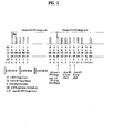
- FIG. 2 is a diagram to illustrate an update of S-SFH IE in IEEE 802.16m system for example of a wireless communication system.
- FIG. 2 shows a case that information contained in S-SFH SP3 IE is changed.
- an S-SFH change cycle is assumed as 32 and that a specific S-SFH SP IE is transmitted at each super frame number (SFN). For instance, if a base station determines that information on a network reentry, which is contained in S-SFH SP3 IE of SFN 30, needs to be changed, a CC (S-SFH change count) is incremented by 1 from SFN 32 with which a next S-SFH change cycle starts. And, a CB (S-SFH change bitmap) is also changed into 100 from 000 to indicate that the changed S-SFH IE is the S-SFH SP3 IE. Moreover, the base station starts to transmit the changed S-SFH SP3 IE.
- SFN super frame number
- a user equipment checks an S-SFH change count field by receiving P-SFH IE.
- the user equipment is aware that the CC (S-SFH change count) in SFN 32 has been incremented by 1 from 'K' saved in the user equipment, and more particularly, that the S-SFH SP IE has been changed.
- the user equipment is aware that the changed S-SFH SP3 IE has been changed from the CB (S-SFH change bitmap) and then waits for the S-SFH SP3 IE.
- the user equipment initially receives the S-SFH SP3 IE changed in SFN 35, decodes the received S-SFH SP3 IE, and is then able to use the changed network reentry information from SFN 36. If a changed S-SFH IE is S-SFH SP1 IE or S-SFH SP2 IE, the changed content may be applicable to a changed S-SFH IE that is transmitted secondly.
- the base station is aware that which S-SFH SP IE of a current superframe should be decoded to update a system parameter contained in S-SFH SP IE.
- AAI-SCD message is provided by a base station to transmit information related to system setup and is transmitted periodically. If a content of the AAI-SCD message is changed, a value of a configuration change count field is incremented (by 1 modulo 16).
- the base station uses an SCD count field of S-SFH SP3 IE to indicate a time at which the changed AAI-SCD message will be applied.
- the base station transmits the S-SFH SP3 IE containing an SCD count equal to the configuration change count in the AAI-SCD and then applies the changed system setup.
- a user equipment receives the system setup information of the AAI-SCD message related to the current SCD count. If the change of the AAI-SCD message is attributed to an update of the S-SFH SP3 IE, a new AAI-SCD message is sent before the changed S-SFH SP. Having received the changed S-SFH SP3, the user equipment may be able to use the system setup of the AAI-SCD message associated with the current SCD count.
- FIG. 3 is a diagram of a state of a user equipment in IEEE 802.16m system for example of a wireless communication system.
- a state of a user equipment may be mainly classified into a connected state and an unconnected state.
- the connected state may be divided into a normal mode and a sleep mode.
- the unconnected state may be divided into an idle mode and a DCR (deregistration with content retention) mode.
- both of the sleep mode and the idle mode are defined to efficiently control power consumption of the user equipment.
- the sleep mode is the mode of operating and managing a sleep mode pattern including a sleep-window and a listening-window granted by the base station through AAI-SLP-REQ/AAI-SLP-RSP message exchange between the user equipment and the base station.
- the idle mode is the mode of operating and managing a paging group, a paging cycle and a paging offset granted by the base station through AAI-DREG-REQ/AAI-DREG-CMD message exchange between the user equipment and the base station to save power and radio resources of the user equipment.
- the normal mode is the mode in which the user equipment performs a service provided by a corresponding system using a radio resource.
- the DCR (deregistration with content retention) mode is the mode in which a content is retained for prescribed duration despite deregistration of the user equipment from a network.
- a user equipment sends AAI-SLP-REQ message to a base station to make a request for a transition to a sleep mode. If the request for the operation in sleep mode is received via the AAI-SLP-REQ message, the base station makes a final grant on the request by sending AAI-SLP-RSP message to the user equipment. Having received the AAI-SLP-RSP message, the user equipment receives an assignment of ID (SLPID) to identify a user equipment operating in sleep mode and then operates the sleep mode.
- SLPID assignment of ID
- major parameters obtained from the message exchanges between the user equipment and the base station include an initial sleep-window for specifying a size of an initial sleep window interval, a final sleep-window base for specifying a size of a final sleep window interval, a final sleep-window exponent, and a listening-window for specifying a size of a listening-window interval, where a unit of each of the parameters is set to a frame.
- the sleep window is in interval in which a user equipment operating in sleep mode minimizes its power. And, the user equipment does not receive DL control information and DL traffic during the sleep-window interval.
- the listening window is an interval in which a user equipment operating in sleep mode gests away from the sleep window, receives AAI-TRF-IND message sent by a base station, and then determines a presence or non-presence of DL traffic transmitted to itself. And, the user equipment may be able to receive DL control information and DL traffic in the sleep-window interval.
- a user equipment sends AAI-DREG-REQ message to a base station to make a request for a transition to the idle mode, receives AAI-DREG- CMD message from the base station, and then operates the idle mode.
- AAI-DREG-REQ message a paging cycle requested by the user equipment is defined.
- AAI-DREG-CMD message sent by the base station having received the AAI-DREG-REQ message a paging group ID, a paging offset and a paging cycle are defined.
- the user equipment sets a paging unavailable interval and a paging listening interval according to the parameters.
- an idle mode may indicate a mode of operating and managing a paging group, paging cycle and paging offset granted by a base station through signaling between the user equipment and the base station.
- the idle mode enables the user equipment to periodically receive a DL broadcast message without registration with a specific base station.
- the paging message is a message to instruct a user equipment of a paging action.
- the paging action may include such an action as a ranging execution, a network reentry and the like.
- An idle mode may be initiated by a user equipment or a base station.
- the user equipment sends a deregistration request (DREG-REQ) message to a base station, receives a deregistration response (DREG-RSP) message from the base station in response to the DREG-REQ message, and may be then able to enter the idle mode.
- DREG-REQ deregistration request
- DREG-RSP deregistration response
- DREG-CMD deregistration command
- a user equipment In case that a user equipment receives a paging message corresponding to the user equipment itself in an available interval (AI), the user equipment switches the idle mode to a connected mode through a network entry procedure with a base station and then transmits and receives data.
- AI available interval
- an idle state or mode operation may mean the operation of supporting a user equipment to perform DL traffic transmission periodically without registration with a specific base station when the user equipment roams around a radio link environment including multiple base stations. If a user equipment does not receive traffic from a base station for predetermined duration, the user equipment may enter an idle state to save power. Having entered the idle mode, the user equipment receives a broadcast message (e.g., a paging message) broadcasted by the base station in an available interval (AI) and may be then able to determine whether to make a transition to a normal mode or remain in the idle state.
- a broadcast message e.g., a paging message
- An idle state may give a benefit to a user equipment by eliminating activation requirements related to handover and general operation requirements.
- the idle state restricts user equipment activity to be scanned in a discrete period, thereby enabling the user equipment to save its power and operating resources.
- the idle state provides a user equipment with a simple and appropriate scheme of indicating DL traffic in pending and give benefits to a network and a base station by removing a radio interface and network handover (HO) traffic from a deactivated user equipment.
- HO radio interface and network handover
- Paging means a function of acquiring a location (e.g., a specific base station, a specific communication exchange, etc.) of a corresponding user equipment in case of an incoming signal occurrence in mobile communication.
- a plurality of idle state or mode supporting base stations may be able to configure a paging area by belonging to a specific paging group.
- the paging group means a logical group.
- the object of the paging group is to provide an adjacent raging area, which can be paged in DL if there is a traffic that targets a user equipment.
- the paging group is configured large enough to have a specific user equipment exist in the same paging group during most of time and also configured small enough for a paging load to be maintained at a proper level.
- a paging group may include at least one or more base stations. And, each of the base stations may belong to one or more paging groups.
- the paging group is defined by a management system.
- a paging group-action backbone network message is usable.
- a paging controller manages a list of user equipments in idle state using a paging-announce message as one of backbone network messages and also manages initial paging of all base stations belonging to the paging group.
- a user equipment sends a deregistration request (DREG-REQ) message to a base station to make a request for a deregistration with the base station.
- DREG-REQ deregistration request
- the base station sends a deregistration response (DREG-RSP) message to the user equipment.
- the DREG-RSP message may contain paging information.
- the entry into the idle mode by the user equipment may be initiated by a request made by the base station. If so, the base station sends a DREG-RSP message to the user equipment.
- the paging information may include values of a paging cycle, a paging offset, a paging group identifier (PGID), a paging listening interval and the like.
- the paging cycle may have the values shown in Table 2.
- Field Size (bits) Value/Description Condition Paging cycle 4 Used to indicate Paging cycle for the AMS 0x00: 4 superframes Values 0x08-0x10 may be applied to M2M devices only. 0x01: 8 superframes 0x02: 16 superframes 0x03: 32 superframes 0x04: 64 superframes 0x05: 128 superframes 0x06: 256 superframes 0x07: 512 superframes 0x08: 32768 superframes 0x09: 262144 superframes 0x10: 4194304 superframes 0x11 -0x15: reserved
- a pair of paging offsets may be assigned to the user equipment.
- a pair of the paging offsets may be represented as Table 3.
- Paging offset 12 Used to indicate Paging offset for the AMS. Determines the superframe within the paging cycle from which the paging listening interval starts. Shall be smaller than Paging cycle value.
- M2M paging offset 10 Used to indicate the superframe within the paging cycle at which the M2M device's paging listening interval starts. May be present when the Paging cycle value is set to 0x08. 0X09. or 0x10 The superframe is determined by concatenating the M2M paging offset field and the Paging offset field M2M paging offset shall be interpreted as the MSB. Shall be smaller than Paging cycle value.
- a user equipment may have to monitor whether the AAI-PAG-ADV message is transmitted in a 2 nd paging offset.
- the AAI-PAG-ADV message is sent in a network reentry step. If a base station fails to receive a corresponding response from a base station, the base station may make a request for a re-page to the user equipment in the 2 nd paging offset to indicate AAI-DREG-RSP message.
- the user equipment Having received DREG-RSP message from the base station, the user equipment enters an idle mode with reference to the paging information.
- the idle mode may have a paging cycle and may be constructed with an available interval and an unavailable interval.
- the available interval has the same concept of a paging listening interval or a paging interval.
- a paging offset is used to indicates a timing point (e.g., frame, subframe, etc.) at which a paging interval starts in a paging cycle.
- a paging group identifier indicates an identifier of a paging group assigned to a user equipment.
- the paging information may include paging message offset information.
- the paging message offset information may indicate a timing point at which a paging message is sent from a base station.
- the user equipment is able to receive a paging message delivered to itself in the available interval (or the paging listening interval) using the paging information.
- the paging message may be transmitted via the base station or a paging controller.
- the user equipment monitors a radio channel in accordance with a paging cycle to receive the paging message.
- a user equipment in idle mode receives a paging message in its paging listening interval and then checks whether there is DL data delivered to the corresponding user equipment. If there is the DL data [i.e., a positive indication], the user equipment performs a network reentry process including a ranging procedure. Thereafter, the user equipment performs a process for establishing a connection for a related DA service flow through DSA (dynamic service addition) process. After the connection for the service flow has been established, a base station transmits DL data of a corresponding service to the user equipment.
- DSA dynamic service addition
- IEEE 802.16e/16m/16p system is taken as an example, by which the technical idea of the present invention may be non-limited.
- a user equipment In order to enter an idle mode, a user equipment sends a deregistration request (DREG-REQ) message to a base station to make a request for a deregistration with the base station.
- DREG-REQ deregistration request
- the base station In response to the DREG-REQ message, the base station then sends a deregistration response 9DREG-RSP) message to the user equipment.
- the DREG-RSP message contains paging information.
- an entry into the idle mode may be initiated by a request made by the base station. In doing so, the base station sends a DREG-RSP message to the user equipment.
- the paging information may include values of a paging cycle, a paging offset, a paging group identifier (PGID), a paging listening interval and the like.
- An idle mode may have a paging cycle and may be constructed with an available interval and an unavailable interval.
- the available interval has the same concept of a paging listening interval or a paging interval.
- a paging offset is used to indicates a timing point (e.g., frame, subframe, etc.) at which a paging interval starts in a paging cycle.
- a paging group identifier indicates an identifier of a paging group assigned to a user equipment.
- the paging information may include paging message offset information.
- the paging message offset information may indicate a timing point at which a paging message is sent from a base station.
- the user equipment may able to receive a paging message delivered to itself in the available interval (or the paging listening interval) using the paging information.
- the paging message may be transmitted via the base station or a paging controller.
- the user equipment monitors a radio channel in accordance with a paging cycle to receive the paging message.
- FIG. 4 is a flowchart to illustrate a paging procedure in idle mode according to the present invention.
- a user equipment in idle mode receives a paging message in its paging listening interval and then checks whether there is DL data delivered to the corresponding user equipment [S1210]. If there is the DL data [i.e., a positive indication], the user equipment performs a network reentry process including a ranging procedure [S1220]. Thereafter, the user equipment performs a process for establishing a connection for a related DA service flow through DSA (dynamic service addition) process [S1230]. After the connection for the service flow has been established or set up, a base station transmits DL control information and data for a corresponding service to the user equipment [S1240].
- DSA dynamic service addition
- M2M server may be able to transmit updated information to every M2M device having the corresponding application installed therein.
- the base station of the embodiment shown in FIG. 4 will page the corresponding M2M devices.
- each of the paged user equipments accesses a network by performing a network reentry process in a manner of initiating a transmission of random access code and may then receive DL traffic transmitted from the base station.
- a user equipment minimizes power in a paging unavailable interval and receives AAI-PAG-ADV message sent from a base station in a paging listening interval.
- the AAI-PAG-ADV message includes an ID of a paging group having the message sending base station belong thereto, MAC address Hash information indicating location-update or network-entry/reentry required user equipments among a plurality of user equipments operating in idle mode, and an action code having the description of a procedure mandatory for each user equipment.
- a base station If traffic to a user equipment operating in idle mode occurs, a base station sends AAI-PAG-ADV message to the user equipment in a next paging listening interval. Having received the AAI-PAG-ADV message, the corresponding user equipment gets away from the idle mode and then enters a normal mode.
- a process for a user equipment to adjust transmission parameters e.g., frequency offset, time offset, transmission power, etc.
- transmission parameters e.g., frequency offset, time offset, transmission power, etc.
- the ranging may have 4 kinds of modes including an initial ranging, a handover ranging, a periodic ranging and a bandwidth request ranging.
- the initial ranging means a process for a user equipment to adjust transmission parameters (e.g., frequency offset, time offset, transmission power, etc.) for an UL communication with a base station in the course of performing an initial network entry procedure.
- the handover ranging means a process for a user equipment to simplify a procedure of handover operation.
- the periodic ranging means a process for a user equipment to persistently maintain a UL communication with a base station after completion of a network entry procedure.
- the bandwidth request ranging means a process performed in the course of requesting a UL band in case of occurrence of traffic to be transmitted to a base station.
- a ranging code (or a ranging preamble) usable according to a ranging type in performing a ranging and a region (i.e., a ranging channel) for carrying the ranging code are assigned via a channel for broadcasting system information (Broadcast Assignment A-MAP IE) by a network.
- Broadcast Assignment A-MAP IE Broadcast Assignment A-MAP IE
- a user equipment selects a specific ranging code from a plurality of ranging codes for the handover ranging and then transmits the selected ranging code to a network on a handover ranging channel.
- the network is then able to identify a type of the ranging through the received ranging code and the ranging code carried channel.
- ranging channels may be classified into a synchronized ranging channel (S-RCH) for a ranging performed by a synchronized user equipment and a non-synchronized ranging channel (NS-RCH) for a ranging performed by a non-synchronized user equipment.
- S-RCH synchronized ranging channel
- NS-RCH non-synchronized ranging channel
- BRCH bandwidth request channel
- a scheme of transmitting assignment information on a ranging code and a ranging channel and the corresponding ranging channel are discriminated in accordance with a type of a base station.
- S-RCH is used.
- the assignment information on a ranging code and a ranging channel is basically carried on a Superframe Header SFH (SP1: Ranging Parameter(RP) code partition information for the S-RCH, allocation periodicity of the S-RCH, subframe offset of the S-RCH, etc.).
- SP1 Ranging Parameter(RP) code partition information for the S-RCH, allocation periodicity of the S-RCH, subframe offset of the S-RCH, etc.
- a base station e.g., a macro, a relay, a macro hot-zone, etc.
- NS-RCH uses NS-RCH in performing an initial ranging or a handover ranging.
- S-RCH is used.
- the assignment information on a ranging code and a ranging channel is basically carried on Superframe Header SFH (SP1: RP code partition information for the NS-RCH, allocation periodicity of the NS-RCH, subframe offset of the NS-RCH, etc.).
- Ranging channel assignment information may be additionally delivered via A-MAP or AAI-SCD message as well as SFH.
- the assignment information on the NS-RCH for the handover ranging may be transmitted on Broadcast Assignment A-MAP IE or AAI-HO-CMD in a subframe except a subframe used for assignment of random normal broadcast data in accordance with a scheduling determination made by a base station.
- AAI-SCD message such information as S-RCH assignment cycle, the number of ranging codes for a periodic ranging and the like is contained in the corresponding message.
- FIG. 5 is a flowchart to illustrate a process for a user equipment to perform a contention based network reentry in IEEE 802.16m system for example of a wireless communication system.
- a user equipment selects a ranging channel, selects a contention based ranging code, and then transmits the contention based ranging code to a base station via the selected ranging channel [S110]. If the base station successfully receives the corresponding ranging code, the base station transmits an AAI-RNG-ACK message to the user equipment by broadcast [S120]. In this case, the AAI-RNG-ACK message is the message that provides a response indicating that the ranging codes have been successfully received and detected from the ranging channel.
- the base station masks CDMA allocation A-MAP IE, which is UL resource allocation information for enabling the user equipment to send an AAI-RNG-REQ message, with a random access identifier (RA-ID) and then transmits the masked CDMA allocation A-MAP IE [S130].
- the user equipment sends the AAI-RNG-REQ message to the base station [S140].
- the base station transmits UL resource allocation information, via which an AAI-RNG-RSP message will be sent, to the user equipment [S150].
- the DL resource allocation information may be transmitted to the user equipment via RA-ID masked CDMA allocation A-MAP IE or broadcast DL basic assignment A-MAP IE. Thereafter, the user equipment may be able to receive the AAI-RNG-RSP message via the corresponding DL resource [S160].
- FIG. 6 is a flowchart to illustrate a process for a user equipment to perform a non-contention based network reentry in IEEE 802.16m system for example of a wireless communication system, which takes a non-contention based handover ranging as an example.
- a serving base station transmits a dedicated ranging code to a user equipment via AAI-HO-CMD message [S210].
- the user equipment transmits the assigned dedicated ranging code to a target base station [S220].
- the target base station informs the user equipment that the corresponding dedicated ranging code has been successfully received, by unicast via a station identifier (STID) based AAI-RNG-ACK message [S230]. Having received the dedicated ranging code, the target base station is already aware which user equipment has transmitted the corresponding dedicated ranging code.
- a station identifier (STID) previously assigned to the user equipment by the target base station is contained as well as the dedicated ranging code.
- the AAI-RNG-ACK message may not be sent on the basis of RA-ID.
- the target base station transmits UL resource allocation information, which enables the user equipment to send an AAI-RNG-REQ message, to the user equipment by unicast via STID based UL basic assignment A-MAP IE [S240].
- the user equipment sends AAI-RNG-REQ message to the target base station via the allocated UL resource [S250].
- the base station then transmits DL resource allocation information, via which an AAI-RNG-RSP message will be sent, via STID based DL basic assignment A-MAP IE [S260]. Thereafter, the user equipment may be able to receive the AAI-RNG-RSP message via the allocated DL resource [S270].
- a base station sends an AAI-HO-CMD message to a user equipment in a manner that a dedicated ranging code and an STID previously assigned to the user equipment by the base station are contained in the AAI-HO-CMD message.
- an M2M device performs a non-contention based ranging for a non-contention based network reentry
- since the M2M device performs a ranging procedure based on a random access identifier (RA-ID) since the M2M device performs a ranging procedure based on a random access identifier (RA-ID), it may cause a problem that this RA-ID based ranging procedure has difficult in being discriminated from other RA-ID based ranging procedures.
- RA-ID random access identifier
- RA-ID is schematically described as follows. First of all, RA-ID is defined with total 15 bits in accordance with a random access property of a corresponding user equipment. In particular, the RA-ID is constructed with 5-bit superframe number, 2-bit frame_index, 6-bit preamble code index for ranging and 2-bit opportunity index for ranging. In particular, the 6-bit preamble code index indicates a ranging code and the 2-bit opportunity index indicates a ranging channel for transmitting the ranging code.
- the opportunity index includes '0b00' indicating a non-synchronized ranging channel (NS-RCH), '0b11' indicating a synchronized ranging channel (S-RCH), and '0b01/0b10' indicating a dynamic ranging channel.
- N-RCH non-synchronized ranging channel
- S-RCH synchronized ranging channel
- '0b01/0b10' indicating a dynamic ranging channel.
- the 6-bit ranging code and the 2-bit ranging channel for carrying the ranging code are manor components for determining the RA-ID.
- FIG. 7 is a flowchart to illustrate a process for an M2M device to perform a non-contention based network reentry according to one embodiment of the present invention.
- a base station may be able to set up one dedicated identifier (e.g., one dedicated STID).
- One dedicated STID set up by the base station is the ID that can be used by an M2M device performing a non-contention based network reentry or by M2M devices in common.
- the base station sends an AAI-PAG-ADV message containing the set one dedicated STID by broadcast [S310].
- the base station transmits a specific IE masked with the set one dedicated STID to the M2M device or the M2M devices in a manner that information on an RA-ID list/set is contained in the specific IE [S320].
- the specific IE may correspond to a UL basic allocation A-MAP IE or a broadcast A-MAP IE.
- it may be able to define a new IE that carries information on RA-ID list/set.
- the M2M device selects a ranging channel, selects a ranging code, and then transmits the ranging code to the base station via the selected ranging channel [S330].
- the base station transmits CDMA allocation A-MAP IE, which is UL resource allocation information for transmitting an AAI-RNG-REQ message, in a manner that the UL resource allocation information is CRC masked with AR-ID [S340].
- the M2M device sends an AAI-RNG-REQ message to the base station via the allocated UL resource [S350].
- the base station then transmits a DL resource allocation information for transmitting an AAI-RNG-RSP message to the M2M device [S360]. Thereafter, the M2M device may be able to receive an AAI-RNG-RSP message via the corresponding DL resource [S370].
- an M2M device in idle mode is awaked in its listening interval and then checks whether system information is changed (e.g., S-SFH change count in P-SFH). If the system information is changed, the corresponding M2M device may have to perform a procedure for acquiring latest system information.
- system information e.g., S-SFH change count in P-SFH.
- the M2M device failing to have the latest system information may not be able to read a paging message transmitted in its listening interval.
- the corresponding M2M device should wait until a next paging cycle or a 2 nd paging offset in the same paging cycle. For example, the corresponding M2M device may wait while sleeping.
- system information may be changed again while waiting despite that latest system information is acquired in the corresponding cycle.
- uplink data may cause such a problem that a procedure for monitoring a presence or non-presence of a change, updating system information and awaiting a reception of a paging message may be infinitely repeated,
- a count of system information changes may exceed a maximum change count applied to the S-SFH change cycle during a paging cycle greater than a prescribed value.
- 'I' is a reference cycle compared with a paging cycle
- 'C' is a change cycle of a secondary superframe header
- 'n' indicates a bit size of a change count of the secondary superframe header.
- a value of C may be set to one of 16, 32, 64 ....
- a value of n may be set to 4.
- system information may be changed over a multiple of 16 times.
- a field value indicating a presence or non-presence of the change of the system information may not be valid any more.
- the field value is equal to a count of system information owned by a user equipment, a corresponding M2M device is not sure whether the system information is not changed, whether the system information has been changed 16 times, or the like. This may cause a problem as well.
- the present invention provides a method of determining whether system information is updated by 2 steps.
- the 2-step update method according to the present invention is just exemplary. And, it is apparent that system information may be updated by each step configuring the 2-step update method.
- a user equipment examines a previous S-SFH change cycle duration.
- a presence or non-presence of a change of a previous duration is checked and system information is updated. This is because system information of a previous change count may be applicable to a partial interval in n duration.
- an S-SFN change cycle duration to which a listening interval of a user equipment in idle state belongs, is set to n and a reference value is set to M.
- a value of M is previously defined and set or may be signaled by a base station. For instance, M is equal to or greater than 1.
- the user equipment may definitely perform a system information update irrespective of a presence or non-presence of a change. For instance, if the following condition is satisfied, the user equipment may be able to instantaneously perform the system information update. In particular, the user equipment should acquire all system informations (e.g., S-SFH SP 1 IE, S-SFH SP 2 IE, and S-SFH SP 3 IE all).
- system informations e.g., S-SFH SP 1 IE, S-SFH SP 2 IE, and S-SFH SP 3 IE all).
- a system information update is performed only if system information is changed.
- the user equipment acquires the changed system information (e.g., at least one of S-SFH SP 1 IE, S-SFH SP 2 IE and S-SFH SP 3 IE) only.
- the corresponding M2M device should perform the 1 st step by resetting a start point in consideration of the corresponding information.
- the corresponding M2M device should perform the 1 st step by resetting a start point in consideration of the corresponding information. In dong so, the m nay be decremented by 1.
- the 2 nd step is the step of examining S-SFH change cycle duration to which a listening interval of the user equipment belongs.
- the reason why a presence or non-presence of a change of the corresponding duration is checked is because system information of a corresponding count in n duration may be applicable only after a partial interval.
- the M2M device performs the system information update only if the system information is changed.
- system information apply field it may be able to apply a system information having an appropriate change count value.
- FIG. 8 is a flowchart for one example of updating system information through a plurality of steps according to one embodiment of the present invention.
- a user equipment determines how far a start point of monitoring S-SFH change cycle duration, to which a listening interval of the user equipment in idle state belongs, will be set behind n [S510].
- the user equipment determines whether an S-SFH change count value is valid [S520].
- the terminal may be able to definitely perform the system information update irrespective or a presence or non-presence of a change of the system information [S560].
- the user equipment determines whether a changed information exists [S530]. If m is equal to or greater than 2, it may be able to decrement the m by 1. And, this routine may be repeated until the m becomes 1.
- the M2M device then performs the system information update only if the system information is changed.
- the corresponding M2M device should perform the 1 st step by resetting a start point in consideration of the corresponding information.
- the user equipment examines a current S-SFH change cycle duration.
- the M2M device performs the system information update only if the system information is changed [S570].
- system information apply field it may be able to apply a system information having an appropriate change count value.
- FIG. 9 is a diagram to illustrate one example of updating system information through a plurality of steps according to one embodiment of the present invention.
- FIG. 9 shows the content of the present invention described with reference to FIG. 8 according to a flow of time.
- a user equipment monitors S-SFH change cycle duration, to which a listening interval of the user equipment in idle state belongs, from (n-1) with reference to n.
- the terminal may be able to definitely perform the system information update irrespective or a presence or non-presence of a change of the system information.
- the user equipment determines whether a changed information exists [S530]. If m is equal to or greater than 2, it may be able to decrement the m by 1. And, this routine may be repeated until the m becomes 1.
- the M2M device then performs the system information update only if the system information is changed.
- the corresponding M2M device should perform the 1 st step by resetting a start point in consideration of the corresponding information.
- the user equipment performs the 2 nd step shown in FIG. 9 to examine a current S-SFH change cycle duration.
- the M2M device is advantageously able to update system information quickly without error occurrence.
- FIG. 10 is a block diagram for configuration of an M2M device and a base station according to one embodiment of the present invention.
- an M2M device 1000 may include an RF unit 1100, a processor 1200 and a memory 1300.
- a base station 1500 may include an RF unit 1600, a processor 1700 and a memory 1800.
- the RF unit 110/160 may include a transmitter 1110/1610 and a receiver 1120/1620.
- the transmitter 1110 is configured to transmit signals to the base station 1500 and other M2M devices.
- the receiver 1120 is configured to receive signals from the base station 1500 and other M2M devices.
- the process 1200 is functionally connected to each of the transmitter 1110 and the receiver 1120 to control a process for the transmitter 1110 and the receiver 1120 to transceive signals with other devices.
- the processor 1200 performs various kinds of processings on a signal to transmit and then transfers the processed signal to the transmitter 1110. And, the processor 1200 may be able to perform processing on a signal received by the receiver 1120. If necessary, the processor 1200 may control information contained in an exchanged message to be saved in the memory 1300.
- the above-configured M2M device 1000 may perform various methods according to embodiments of the present invention mentioned in the foregoing description.
- the M2M device 1000 may further include various kinds of additional components (not shown in FIG. 10 ) according to its machine application types.
- the corresponding M2M device 1000 may further include an additional configuration for power measurement and the like. This power measuring operation may be performed under the control of the processor 1200 shown in FIG. 10 or a separately configured processor (not shown in the drawing).
- FIG. 10 shows a case that a communication is performed between the M2M device 1000 and the base station 1500
- an M2M communication method according to the present invention may be performed between M2M devices.
- the transmitter 1610 of the base station 1500 is configured to transmit signals to another base station, an M2M server and M2M devices.
- the receiver 1620 of the base station 1500 is configured to receive signals from another base station, an M2M server and M2M devices.
- the process 1700 is functionally connected to each of the transmitter 1610 and the receiver 1620 to control a process for the transmitter 1610 and the receiver 1620 to transceive signals with other devices or user equipments.
- the processor 1700 performs various kinds of processings on a signal to transmit and then transfers the processed signal to the transmitter 1610. And, the processor 1700 may be able to perform processing on a signal received by the receiver 1620. If necessary, the processor 1700 may control information contained in an exchanged message to be saved in the memory 1800.
- the above-configured base station 1500 may perform various methods according to embodiments of the present invention mentioned in the foregoing description.
- the processor 1200 of the M2M device 1000 directs operations (e.g., control, adjustment, management, etc.) in the M2M device 1000.
- the processor 1700 of the base station 1500 directs operations (e.g., control, adjustment, management, etc.) in the base station 1500.
- the processor 1200/1700 may be connected to the memory 1300/1800 configured to store program codes and data.
- the memory 1300/1800 is connected to the processor 1200/1700 to store operating systems, applications and general files.
- the processor 1200/1700 may be named one of a controller, a microcontroller, a microprocessor, a microcomputer and the like. Moreover, the processor 1200/1700 may be implemented by hardware, firmware, software or a combination thereof. In case of implementing an embodiment of the present invention using hardware, the processor 120/170 may be provided with such a configuration to perform the present invention as ASICs (application specific integrated circuits), DSPs (digital signal processors), DSPDs (digital signal processing devices), PLDs (programmable logic devices), FPGAs (field programmable gate arrays), and the like.
- ASICs application specific integrated circuits
- DSPs digital signal processors
- DSPDs digital signal processing devices
- PLDs programmable logic devices
- FPGAs field programmable gate arrays
- the firmware or software may be configured to include modules, procedures, and/or functions for performing the functions or operations of the present invention. And, the firmware or software configured to perform the present invention may be driven by the processor 1200/1700 in a manner of being installed at the processor 1200/1700 or being saved in the memory 1300/1800.
- a method for an M2M device to perform a network reentry may be applicable to such a wireless communication system as 3GPP LTE-A system, IEEE 802 system and the like.
Landscapes
- Engineering & Computer Science (AREA)
- Computer Networks & Wireless Communication (AREA)
- Signal Processing (AREA)
- Mobile Radio Communication Systems (AREA)
Claims (12)
- Verfahren zum Dekodieren von Superframe-Header-Unterpaket-Information in einem M2M, Maschine-zu-Maschine, -Gerät in einem Idle-Modus in einem drahtlosen Kommunikationssystem, umfassend die Schritte:Vergleichen eines Pagingzyklus mit einem ersten Zyklus; undfalls der Pagingzyklus gleich ist wie oder größer ist als der erste Zyklus, Dekodieren der Superframe-Header-Unterpaket-Information,wobei der erste Zyklus ermittelt wird unter Verwendung einer folgenden Formel:I = C x 2n, wobei das I den ersten Zyklus angibt, das C ein Änderungszyklus eines sekundären Superframe-Headers ist, und das n eine Bitgröße eines Änderungszählers des sekundären Superframe-Headers ist.
- Verfahren nach Anspruch 1, wobei der Änderungszyklus des sekundären Superframe-Headers eines ausgewählt aus der Gruppe bestehend aus 16, 32 und 64 umfasst.
- Verfahren nach Anspruch 1, wobei die Bitgröße des Änderungszählers des sekundären Superframe-Headers 4 ist.
- Verfahren nach Anspruch 1, ferner umfassend die Schritte:Senden einer ersten Nachricht an eine Basisstation, um eine Anfrage für den Pagingzyklus zu machen; undEmpfangen einer zweiten den Pagingzyklus enthaltenden Nachricht in Antwort auf die gesendete erste Nachricht.
- Verfahren nach Anspruch 1, ferner umfassend die Schritte:falls der Pagingzyklus kleiner ist als der erste Zyklus, ermitteln, ob eine Systeminformation geändert ist; undfalls die Systeminformation geändert ist, Dekodieren der Superframe-Header-Unterpaket-Information.
- Verfahren nach Anspruch 5, wobei, falls der Änderungszyklus des sekundären Superframe-Headers geändert ist, die Systeminformation als geändert bestimmt wird.
- M2M, Maschine-zu-Maschine, -Gerät, welches Superframe-Header-Unterpaket-Information in einem Idle-Modus in einem drahtlosen Kommunikationssystem dekodiert, umfassend:einen Prozessor, der einen Pagingzyklus mit einem ersten Zyklus vergleicht, wobei der Prozessor, falls der Pagingzyklus gleich ist oder größer ist als der erste Zyklus, die Superframe-Header-Unterpaket-Information dekodiert, wobei der Prozessor die Ermittlung des ersten Zyklus unter Verwendung einer folgenden Formel steuert:I = C × 2n, wobei das I den ersten Zyklus angibt, das C ein Änderungszyklus eines sekundären Superframe-Headers ist, und das n eine Bitgröße eines Änderungszählers des sekundären Superframe-Headers ist.
- M2M-Gerät nach Anspruch 7, wobei der Änderungszyklus des sekundären Superframe-Headers eines ausgewählt aus der Gruppe bestehend aus 16, 32 und 64 umfasst.
- M2M-Gerät nach Anspruch 7, wobei die Bitgröße des Änderungszählers des sekundären Superframe-Headers 4 ist.
- M2M-Gerät nach Anspruch 7, ferner umfassend:ein Sendemodul, das eine erste Nachricht an eine Basisstation aussendet, um eine Anfrage für den Pagingzyklus zu machen; undein Empfangsmodul, das eine zweite Nachricht empfängt, die den Pagingzyklus enthält, in Antwort auf die gesendete erste Nachricht.
- M2M-Gerät nach Anspruch 7, wobei, falls der Pagingzyklus kleiner ist als der erste Zyklus, der Prozessor ermittelt, ob eine Systeminformation geändert ist, und wobei, falls die Systeminformation geändert ist, der Prozessor die Dekodierung der Superframe-Header-Unterpaket-Information steuert.
- M2M-Gerät nach Anspruch 11, wobei, falls der Änderungszyklus des sekundären Superframe-Headers geändert ist, der Prozessor bestimmt, dass die Systeminformation geändert ist.
Applications Claiming Priority (4)
| Application Number | Priority Date | Filing Date | Title |
|---|---|---|---|
| US201161526690P | 2011-08-24 | 2011-08-24 | |
| US201161529932P | 2011-09-01 | 2011-09-01 | |
| US201161531089P | 2011-09-06 | 2011-09-06 | |
| US201161532567P | 2011-09-09 | 2011-09-09 |
Publications (2)
| Publication Number | Publication Date |
|---|---|
| EP2563080A1 EP2563080A1 (de) | 2013-02-27 |
| EP2563080B1 true EP2563080B1 (de) | 2014-05-07 |
Family
ID=46125138
Family Applications (1)
| Application Number | Title | Priority Date | Filing Date |
|---|---|---|---|
| EP12003572.0A Not-in-force EP2563080B1 (de) | 2011-08-24 | 2012-05-08 | Aktualisieren von Informationen einer M2M-Vorrichtung in einem drahtlosen Kommunikationssystem |
Country Status (3)
| Country | Link |
|---|---|
| US (1) | US8774849B2 (de) |
| EP (1) | EP2563080B1 (de) |
| CN (1) | CN102958158B (de) |
Cited By (1)
| Publication number | Priority date | Publication date | Assignee | Title |
|---|---|---|---|---|
| CN108419281A (zh) * | 2015-11-28 | 2018-08-17 | 广东欧珀移动通信有限公司 | 一种网络切换方法、装置及通信终端 |
Families Citing this family (10)
| Publication number | Priority date | Publication date | Assignee | Title |
|---|---|---|---|---|
| CN103348748A (zh) * | 2011-02-09 | 2013-10-09 | 交互数字专利控股公司 | 用于对机器对机器装置的下行链路数据执行寻呼的方法 |
| US8774849B2 (en) * | 2011-08-24 | 2014-07-08 | Lg Electronics Inc. | Apparatus for updating information of an M2M device in a wireless communication system and method thereof |
| US8891424B2 (en) * | 2011-10-16 | 2014-11-18 | Lg Electronics Inc. | Method and device for monitoring paging message |
| US9451587B2 (en) * | 2013-05-03 | 2016-09-20 | Telefonaktiebolaget Lm Ericsson (Publ) | Paging for longer paging cycles |
| CN105359555B (zh) * | 2013-07-01 | 2019-04-23 | Lg 电子株式会社 | 终端的直接设备对设备通信的方法及其设备 |
| US9241340B2 (en) * | 2014-01-23 | 2016-01-19 | Humax Holdings Co., Ltd. | Apparatus for scheduling in LTE machine type communication |
| AU2015274403A1 (en) * | 2014-06-13 | 2017-01-05 | Uber Technologies, Inc. | Enforcing policies based on information received from external systems |
| US9544395B2 (en) | 2014-10-10 | 2017-01-10 | At&T Intellectual Property I, L.P. | Facilitating quality of service and security via functional classification of devices in networks |
| US9980284B2 (en) | 2015-03-13 | 2018-05-22 | Huawei Technologies Co., Ltd. | Contention-based reservations of network resources |
| US11290323B2 (en) * | 2017-04-13 | 2022-03-29 | Qualcomm Incorporated | Configuring multi-channel transmission for ranging accuracy |
Family Cites Families (34)
| Publication number | Priority date | Publication date | Assignee | Title |
|---|---|---|---|---|
| DE69030490T2 (de) * | 1990-01-18 | 1997-10-23 | Philips Electronics N.V., Eindhoven | Aufzeichnungsvorrichtung zum umkehrbaren Speichern von digitalen Daten auf einem Mehrspuren-Aufzeichnungsträger, Dekodiervorrichtung, Informationswiedergabegerät für die Verwendung mit einem solchen Aufzeichnungsträger und Aufzeichnungsträger für die Verwendung mit einer solchen Aufzeichnungsvorrichtung, mit einer solchen Dekodiervorrichtung und/oder mit einem solchen Informationswiedergabegerät |
| US5604744A (en) * | 1992-10-05 | 1997-02-18 | Telefonaktiebolaget Lm Ericsson | Digital control channels having logical channels for multiple access radiocommunication |
| US6795425B1 (en) * | 1998-11-12 | 2004-09-21 | Ericsson Inc. | Wireless communications methods and apparatus employing paging attribute descriptors |
| US7613209B1 (en) * | 2004-03-30 | 2009-11-03 | Extreme Networks, Inc. | System and method for egress packet marking |
| US7539750B1 (en) * | 2004-03-30 | 2009-05-26 | Extreme Networks, Inc. | System and method for packet processor status monitoring |
| US7304996B1 (en) * | 2004-03-30 | 2007-12-04 | Extreme Networks, Inc. | System and method for assembling a data packet |
| US7092721B2 (en) * | 2004-07-20 | 2006-08-15 | Motorola, Inc. | Reducing delay in setting up calls |
| US7912491B2 (en) * | 2006-10-10 | 2011-03-22 | Intel Corporation | Techniques to efficiently transmit control messages to idle and sleep mode users in OFDMA based wireless networks |
| BRPI0807689A2 (pt) * | 2007-02-28 | 2014-07-08 | Ntt Docomo Inc | Aparelho de estação base e método de controle de comunicação. |
| CN102077620B (zh) * | 2008-04-25 | 2015-05-13 | 三星电子株式会社 | 无线通信系统中用于提供紧急服务的装置和方法 |
| KR20090117578A (ko) * | 2008-05-08 | 2009-11-12 | 엘지전자 주식회사 | 헤더를 이용한 페이징 방법 |
| KR20090117570A (ko) * | 2008-05-08 | 2009-11-12 | 엘지전자 주식회사 | 페이징 방법 |
| KR101199389B1 (ko) * | 2008-05-09 | 2012-11-12 | 엘지전자 주식회사 | 무선접속시스템에서 페이징 수행 방법 |
| KR101169283B1 (ko) * | 2008-06-03 | 2012-08-02 | 엘지전자 주식회사 | 광대역 무선 접속 시스템에서 페이징 정보 송수신 방법 |
| KR20090129289A (ko) * | 2008-06-11 | 2009-12-16 | 엘지전자 주식회사 | 페이징 메시지 송수신 방법 |
| US8416746B2 (en) * | 2008-07-07 | 2013-04-09 | Apple Inc. | Medium access control for wireless systems |
| WO2010071347A2 (en) * | 2008-12-15 | 2010-06-24 | Lg Electronics Inc. | Method for saving power of a femto base station using sleep period synchronization |
| US20100271175A1 (en) * | 2009-04-24 | 2010-10-28 | Industrial Technology Research Institute | Methods and apparatuses for providing a paging process for multicarrier |
| KR101597092B1 (ko) * | 2009-06-24 | 2016-02-25 | 삼성전자주식회사 | 무선통신 시스템에서 페이징 제어 정보를 전송하기 위한 방법 및 장치 |
| JP5854450B2 (ja) * | 2010-01-13 | 2016-02-09 | 日本電気株式会社 | 無線通信システム、無線通信装置、無線通信方法及びプログラム |
| KR101823475B1 (ko) | 2010-02-09 | 2018-01-30 | 엘지전자 주식회사 | Mtc 기기가 사용되는 이동통신시스템에서 메시지 송수신 방법 및 이를 위한 장치 |
| EP2534904B1 (de) | 2010-02-10 | 2014-07-23 | Telefonaktiebolaget L M Ericsson (publ) | Verfahren und anordnung in einem telekommunikationssystem |
| GB201005312D0 (en) * | 2010-03-30 | 2010-05-12 | Vodafone Ip Licensing Ltd | Device and method of operation |
| KR20110121559A (ko) * | 2010-04-30 | 2011-11-07 | 한국전자통신연구원 | 기지국, 이동국, 페이징 메시지 전송 방법, 및 페이징 메시지 수신 방법 |
| WO2012011782A2 (ko) * | 2010-07-22 | 2012-01-26 | 엘지전자 주식회사 | 이동성이 없는 유휴상태 단말의 네트워크 재진입 방법 및 이를 지원하는 방법 |
| RU2562059C2 (ru) * | 2010-07-22 | 2015-09-10 | Эл Джи Электроникс Инк. | Способ и устройство для передачи и приема данных нисходящей линии связи для мобильной станции без мобильности в состоянии бездействия |
| US9408236B2 (en) * | 2010-07-25 | 2016-08-02 | Lg Electronics Inc. | Method for distributing random access, method for distributing and performing random access, and device therefor |
| KR101871720B1 (ko) * | 2010-11-05 | 2018-06-27 | 엘지전자 주식회사 | 무선 통신 시스템에서 단말의 plmn 정보 선택 방법 및 이를 위한 장치 |
| TW201603506A (zh) * | 2011-01-10 | 2016-01-16 | 內數位專利控股公司 | 在肌器對機器或行動輔助佈署中呼叫方法及裝置 |
| WO2012138148A2 (ko) * | 2011-04-06 | 2012-10-11 | 엘지전자 주식회사 | 파라미터 업데이트 정보를 전송 및 수신하는 방법과 이를 위한 장치 |
| CN103477574B (zh) * | 2011-04-12 | 2016-04-13 | Lg电子株式会社 | 用于在无线通信系统中在m2m装置上执行测距的方法和设备 |
| WO2012153971A2 (ko) * | 2011-05-08 | 2012-11-15 | 엘지전자 주식회사 | 무선접속시스템에서 m2m 기기들에 멀티캐스트 데이터를 전송하는 방법 및 장치 |
| WO2012177029A2 (ko) * | 2011-06-19 | 2012-12-27 | 엘지전자 주식회사 | M2m 환경을 지원하는 무선접속시스템에서 비정상 정전 상황을 보고하기 위한 임의접속과정 수행방법 |
| US8774849B2 (en) * | 2011-08-24 | 2014-07-08 | Lg Electronics Inc. | Apparatus for updating information of an M2M device in a wireless communication system and method thereof |
-
2012
- 2012-04-26 US US13/456,998 patent/US8774849B2/en not_active Expired - Fee Related
- 2012-05-08 EP EP12003572.0A patent/EP2563080B1/de not_active Not-in-force
- 2012-06-06 CN CN201210184551.9A patent/CN102958158B/zh not_active Expired - Fee Related
Cited By (1)
| Publication number | Priority date | Publication date | Assignee | Title |
|---|---|---|---|---|
| CN108419281A (zh) * | 2015-11-28 | 2018-08-17 | 广东欧珀移动通信有限公司 | 一种网络切换方法、装置及通信终端 |
Also Published As
| Publication number | Publication date |
|---|---|
| EP2563080A1 (de) | 2013-02-27 |
| US20130053084A1 (en) | 2013-02-28 |
| CN102958158B (zh) | 2017-06-06 |
| US8774849B2 (en) | 2014-07-08 |
| CN102958158A (zh) | 2013-03-06 |
Similar Documents
| Publication | Publication Date | Title |
|---|---|---|
| EP2563080B1 (de) | Aktualisieren von Informationen einer M2M-Vorrichtung in einem drahtlosen Kommunikationssystem | |
| US8737305B2 (en) | Method for allocating resources in broadband wireless access system | |
| JP5770948B2 (ja) | 無線接続システムにおいてmac制御メッセージを放送する方法及び装置 | |
| US9510312B2 (en) | Method and apparatus for performing network entry/reentry in wireless communication system | |
| US9319894B2 (en) | Method for transmitting and receiving power outage report and device therefor | |
| US9161177B2 (en) | Method for transmitting and receiving multicast-data-related information by a machine-to-machine (M2M) device in a wireless communication system, and apparatus therefor | |
| US20130252643A1 (en) | Method for transmitting and receiving idle-mode parameter update information, and apparatus therefor | |
| US9191942B2 (en) | Method and device for allocating group resources for M2M device in wireless communication system | |
| US20130121303A1 (en) | Method for distributing random access, method for distributing and performing random access, and device therefor | |
| US9344859B2 (en) | Method of receiving multicast data in a wireless communication system, and device for same | |
| US9125026B2 (en) | Method for receiving multicast data in wireless communication system and M2M device therefor | |
| JP5767396B2 (ja) | 無線通信システムにおいてm2m装置のレンジング方法及び装置 | |
| JP5596883B2 (ja) | 無線通信システムにおいてネットワーク再進入を行う方法及びその装置 | |
| JP5711422B2 (ja) | 無線通信システムにおけるm2m装置の測距方法及び装置 | |
| KR101978221B1 (ko) | 기기간 통신을 지원하는 시스템에서 시스템 정보를 송수신하는 방법 및 장치 | |
| WO2013085128A1 (en) | Method and apparatus for transmitting a mac control message in wireless access system | |
| US20140126459A1 (en) | Method and apparatus for transmitting broadcasting message in wireless access system supporting m2m environment |
Legal Events
| Date | Code | Title | Description |
|---|---|---|---|
| PUAI | Public reference made under article 153(3) epc to a published international application that has entered the european phase |
Free format text: ORIGINAL CODE: 0009012 |
|
| 17P | Request for examination filed |
Effective date: 20120508 |
|
| AK | Designated contracting states |
Kind code of ref document: A1 Designated state(s): AL AT BE BG CH CY CZ DE DK EE ES FI FR GB GR HR HU IE IS IT LI LT LU LV MC MK MT NL NO PL PT RO RS SE SI SK SM TR |
|
| AX | Request for extension of the european patent |
Extension state: BA ME |
|
| GRAP | Despatch of communication of intention to grant a patent |
Free format text: ORIGINAL CODE: EPIDOSNIGR1 |
|
| RIC1 | Information provided on ipc code assigned before grant |
Ipc: H04W 68/00 20090101AFI20131212BHEP |
|
| INTG | Intention to grant announced |
Effective date: 20140107 |
|
| GRAS | Grant fee paid |
Free format text: ORIGINAL CODE: EPIDOSNIGR3 |
|
| GRAA | (expected) grant |
Free format text: ORIGINAL CODE: 0009210 |
|
| AK | Designated contracting states |
Kind code of ref document: B1 Designated state(s): AL AT BE BG CH CY CZ DE DK EE ES FI FR GB GR HR HU IE IS IT LI LT LU LV MC MK MT NL NO PL PT RO RS SE SI SK SM TR |
|
| REG | Reference to a national code |
Ref country code: GB Ref legal event code: FG4D |
|
| REG | Reference to a national code |
Ref country code: AT Ref legal event code: REF Ref document number: 667488 Country of ref document: AT Kind code of ref document: T Effective date: 20140515 |
|
| REG | Reference to a national code |
Ref country code: IE Ref legal event code: FG4D |
|
| REG | Reference to a national code |
Ref country code: DE Ref legal event code: R096 Ref document number: 602012001583 Country of ref document: DE Effective date: 20140626 |
|
| REG | Reference to a national code |
Ref country code: NL Ref legal event code: T3 |
|
| REG | Reference to a national code |
Ref country code: AT Ref legal event code: MK05 Ref document number: 667488 Country of ref document: AT Kind code of ref document: T Effective date: 20140507 |
|
| REG | Reference to a national code |
Ref country code: LT Ref legal event code: MG4D |
|
| PG25 | Lapsed in a contracting state [announced via postgrant information from national office to epo] |
Ref country code: LT Free format text: LAPSE BECAUSE OF FAILURE TO SUBMIT A TRANSLATION OF THE DESCRIPTION OR TO PAY THE FEE WITHIN THE PRESCRIBED TIME-LIMIT Effective date: 20140507 Ref country code: GR Free format text: LAPSE BECAUSE OF FAILURE TO SUBMIT A TRANSLATION OF THE DESCRIPTION OR TO PAY THE FEE WITHIN THE PRESCRIBED TIME-LIMIT Effective date: 20140808 Ref country code: CY Free format text: LAPSE BECAUSE OF FAILURE TO SUBMIT A TRANSLATION OF THE DESCRIPTION OR TO PAY THE FEE WITHIN THE PRESCRIBED TIME-LIMIT Effective date: 20140507 Ref country code: NO Free format text: LAPSE BECAUSE OF FAILURE TO SUBMIT A TRANSLATION OF THE DESCRIPTION OR TO PAY THE FEE WITHIN THE PRESCRIBED TIME-LIMIT Effective date: 20140807 Ref country code: FI Free format text: LAPSE BECAUSE OF FAILURE TO SUBMIT A TRANSLATION OF THE DESCRIPTION OR TO PAY THE FEE WITHIN THE PRESCRIBED TIME-LIMIT Effective date: 20140507 Ref country code: IS Free format text: LAPSE BECAUSE OF FAILURE TO SUBMIT A TRANSLATION OF THE DESCRIPTION OR TO PAY THE FEE WITHIN THE PRESCRIBED TIME-LIMIT Effective date: 20140907 |
|
| PG25 | Lapsed in a contracting state [announced via postgrant information from national office to epo] |
Ref country code: AT Free format text: LAPSE BECAUSE OF FAILURE TO SUBMIT A TRANSLATION OF THE DESCRIPTION OR TO PAY THE FEE WITHIN THE PRESCRIBED TIME-LIMIT Effective date: 20140507 Ref country code: RS Free format text: LAPSE BECAUSE OF FAILURE TO SUBMIT A TRANSLATION OF THE DESCRIPTION OR TO PAY THE FEE WITHIN THE PRESCRIBED TIME-LIMIT Effective date: 20140507 Ref country code: HR Free format text: LAPSE BECAUSE OF FAILURE TO SUBMIT A TRANSLATION OF THE DESCRIPTION OR TO PAY THE FEE WITHIN THE PRESCRIBED TIME-LIMIT Effective date: 20140507 Ref country code: LV Free format text: LAPSE BECAUSE OF FAILURE TO SUBMIT A TRANSLATION OF THE DESCRIPTION OR TO PAY THE FEE WITHIN THE PRESCRIBED TIME-LIMIT Effective date: 20140507 Ref country code: ES Free format text: LAPSE BECAUSE OF FAILURE TO SUBMIT A TRANSLATION OF THE DESCRIPTION OR TO PAY THE FEE WITHIN THE PRESCRIBED TIME-LIMIT Effective date: 20140507 Ref country code: SE Free format text: LAPSE BECAUSE OF FAILURE TO SUBMIT A TRANSLATION OF THE DESCRIPTION OR TO PAY THE FEE WITHIN THE PRESCRIBED TIME-LIMIT Effective date: 20140507 Ref country code: PL Free format text: LAPSE BECAUSE OF FAILURE TO SUBMIT A TRANSLATION OF THE DESCRIPTION OR TO PAY THE FEE WITHIN THE PRESCRIBED TIME-LIMIT Effective date: 20140507 |
|
| PG25 | Lapsed in a contracting state [announced via postgrant information from national office to epo] |
Ref country code: PT Free format text: LAPSE BECAUSE OF FAILURE TO SUBMIT A TRANSLATION OF THE DESCRIPTION OR TO PAY THE FEE WITHIN THE PRESCRIBED TIME-LIMIT Effective date: 20140908 |
|
| PG25 | Lapsed in a contracting state [announced via postgrant information from national office to epo] |
Ref country code: SK Free format text: LAPSE BECAUSE OF FAILURE TO SUBMIT A TRANSLATION OF THE DESCRIPTION OR TO PAY THE FEE WITHIN THE PRESCRIBED TIME-LIMIT Effective date: 20140507 Ref country code: EE Free format text: LAPSE BECAUSE OF FAILURE TO SUBMIT A TRANSLATION OF THE DESCRIPTION OR TO PAY THE FEE WITHIN THE PRESCRIBED TIME-LIMIT Effective date: 20140507 Ref country code: BE Free format text: LAPSE BECAUSE OF FAILURE TO SUBMIT A TRANSLATION OF THE DESCRIPTION OR TO PAY THE FEE WITHIN THE PRESCRIBED TIME-LIMIT Effective date: 20140507 Ref country code: DK Free format text: LAPSE BECAUSE OF FAILURE TO SUBMIT A TRANSLATION OF THE DESCRIPTION OR TO PAY THE FEE WITHIN THE PRESCRIBED TIME-LIMIT Effective date: 20140507 Ref country code: CZ Free format text: LAPSE BECAUSE OF FAILURE TO SUBMIT A TRANSLATION OF THE DESCRIPTION OR TO PAY THE FEE WITHIN THE PRESCRIBED TIME-LIMIT Effective date: 20140507 Ref country code: RO Free format text: LAPSE BECAUSE OF FAILURE TO SUBMIT A TRANSLATION OF THE DESCRIPTION OR TO PAY THE FEE WITHIN THE PRESCRIBED TIME-LIMIT Effective date: 20140507 |
|
| REG | Reference to a national code |
Ref country code: DE Ref legal event code: R097 Ref document number: 602012001583 Country of ref document: DE |
|
| REG | Reference to a national code |
Ref country code: IE Ref legal event code: MM4A |
|
| PLBE | No opposition filed within time limit |
Free format text: ORIGINAL CODE: 0009261 |
|
| STAA | Information on the status of an ep patent application or granted ep patent |
Free format text: STATUS: NO OPPOSITION FILED WITHIN TIME LIMIT |
|
| 26N | No opposition filed |
Effective date: 20150210 |
|
| PG25 | Lapsed in a contracting state [announced via postgrant information from national office to epo] |
Ref country code: IT Free format text: LAPSE BECAUSE OF FAILURE TO SUBMIT A TRANSLATION OF THE DESCRIPTION OR TO PAY THE FEE WITHIN THE PRESCRIBED TIME-LIMIT Effective date: 20140507 Ref country code: IE Free format text: LAPSE BECAUSE OF NON-PAYMENT OF DUE FEES Effective date: 20140508 |
|
| REG | Reference to a national code |
Ref country code: DE Ref legal event code: R097 Ref document number: 602012001583 Country of ref document: DE Effective date: 20150210 |
|
| PG25 | Lapsed in a contracting state [announced via postgrant information from national office to epo] |
Ref country code: SI Free format text: LAPSE BECAUSE OF FAILURE TO SUBMIT A TRANSLATION OF THE DESCRIPTION OR TO PAY THE FEE WITHIN THE PRESCRIBED TIME-LIMIT Effective date: 20140507 |
|
| REG | Reference to a national code |
Ref country code: CH Ref legal event code: PL |
|
| PG25 | Lapsed in a contracting state [announced via postgrant information from national office to epo] |
Ref country code: LI Free format text: LAPSE BECAUSE OF NON-PAYMENT OF DUE FEES Effective date: 20150531 Ref country code: CH Free format text: LAPSE BECAUSE OF NON-PAYMENT OF DUE FEES Effective date: 20150531 |
|
| PG25 | Lapsed in a contracting state [announced via postgrant information from national office to epo] |
Ref country code: MT Free format text: LAPSE BECAUSE OF FAILURE TO SUBMIT A TRANSLATION OF THE DESCRIPTION OR TO PAY THE FEE WITHIN THE PRESCRIBED TIME-LIMIT Effective date: 20140507 |
|
| PG25 | Lapsed in a contracting state [announced via postgrant information from national office to epo] |
Ref country code: SM Free format text: LAPSE BECAUSE OF FAILURE TO SUBMIT A TRANSLATION OF THE DESCRIPTION OR TO PAY THE FEE WITHIN THE PRESCRIBED TIME-LIMIT Effective date: 20140507 Ref country code: MC Free format text: LAPSE BECAUSE OF FAILURE TO SUBMIT A TRANSLATION OF THE DESCRIPTION OR TO PAY THE FEE WITHIN THE PRESCRIBED TIME-LIMIT Effective date: 20140507 |
|
| REG | Reference to a national code |
Ref country code: FR Ref legal event code: PLFP Year of fee payment: 5 |
|
| PG25 | Lapsed in a contracting state [announced via postgrant information from national office to epo] |
Ref country code: BG Free format text: LAPSE BECAUSE OF FAILURE TO SUBMIT A TRANSLATION OF THE DESCRIPTION OR TO PAY THE FEE WITHIN THE PRESCRIBED TIME-LIMIT Effective date: 20140507 |
|
| PG25 | Lapsed in a contracting state [announced via postgrant information from national office to epo] |
Ref country code: LU Free format text: LAPSE BECAUSE OF NON-PAYMENT OF DUE FEES Effective date: 20140508 Ref country code: HU Free format text: LAPSE BECAUSE OF FAILURE TO SUBMIT A TRANSLATION OF THE DESCRIPTION OR TO PAY THE FEE WITHIN THE PRESCRIBED TIME-LIMIT; INVALID AB INITIO Effective date: 20120508 Ref country code: TR Free format text: LAPSE BECAUSE OF FAILURE TO SUBMIT A TRANSLATION OF THE DESCRIPTION OR TO PAY THE FEE WITHIN THE PRESCRIBED TIME-LIMIT Effective date: 20140507 |
|
| REG | Reference to a national code |
Ref country code: FR Ref legal event code: PLFP Year of fee payment: 6 |
|
| PGFP | Annual fee paid to national office [announced via postgrant information from national office to epo] |
Ref country code: NL Payment date: 20170406 Year of fee payment: 6 |
|
| PGFP | Annual fee paid to national office [announced via postgrant information from national office to epo] |
Ref country code: GB Payment date: 20170407 Year of fee payment: 6 Ref country code: FR Payment date: 20170410 Year of fee payment: 6 Ref country code: DE Payment date: 20170406 Year of fee payment: 6 |
|
| PG25 | Lapsed in a contracting state [announced via postgrant information from national office to epo] |
Ref country code: MK Free format text: LAPSE BECAUSE OF FAILURE TO SUBMIT A TRANSLATION OF THE DESCRIPTION OR TO PAY THE FEE WITHIN THE PRESCRIBED TIME-LIMIT Effective date: 20140507 |
|
| PG25 | Lapsed in a contracting state [announced via postgrant information from national office to epo] |
Ref country code: AL Free format text: LAPSE BECAUSE OF FAILURE TO SUBMIT A TRANSLATION OF THE DESCRIPTION OR TO PAY THE FEE WITHIN THE PRESCRIBED TIME-LIMIT Effective date: 20140507 |
|
| REG | Reference to a national code |
Ref country code: DE Ref legal event code: R119 Ref document number: 602012001583 Country of ref document: DE |
|
| REG | Reference to a national code |
Ref country code: NL Ref legal event code: MM Effective date: 20180601 |
|
| GBPC | Gb: european patent ceased through non-payment of renewal fee |
Effective date: 20180508 |
|
| PG25 | Lapsed in a contracting state [announced via postgrant information from national office to epo] |
Ref country code: DE Free format text: LAPSE BECAUSE OF NON-PAYMENT OF DUE FEES Effective date: 20181201 Ref country code: NL Free format text: LAPSE BECAUSE OF NON-PAYMENT OF DUE FEES Effective date: 20180601 Ref country code: FR Free format text: LAPSE BECAUSE OF NON-PAYMENT OF DUE FEES Effective date: 20180531 Ref country code: GB Free format text: LAPSE BECAUSE OF NON-PAYMENT OF DUE FEES Effective date: 20180508 |