EP2563207B1 - Détermination optique de la perfusion sanguine et de paramètres similaires - Google Patents
Détermination optique de la perfusion sanguine et de paramètres similaires Download PDFInfo
- Publication number
- EP2563207B1 EP2563207B1 EP10707430.4A EP10707430A EP2563207B1 EP 2563207 B1 EP2563207 B1 EP 2563207B1 EP 10707430 A EP10707430 A EP 10707430A EP 2563207 B1 EP2563207 B1 EP 2563207B1
- Authority
- EP
- European Patent Office
- Prior art keywords
- light source
- light
- attenuation
- parameter
- signal
- Prior art date
- Legal status (The legal status is an assumption and is not a legal conclusion. Google has not performed a legal analysis and makes no representation as to the accuracy of the status listed.)
- Active
Links
Images




Classifications
-
- A—HUMAN NECESSITIES
- A61—MEDICAL OR VETERINARY SCIENCE; HYGIENE
- A61B—DIAGNOSIS; SURGERY; IDENTIFICATION
- A61B5/00—Measuring for diagnostic purposes; Identification of persons
- A61B5/145—Measuring characteristics of blood in vivo, e.g. gas concentration or pH-value ; Measuring characteristics of body fluids or tissues, e.g. interstitial fluid or cerebral tissue
- A61B5/1455—Measuring characteristics of blood in vivo, e.g. gas concentration or pH-value ; Measuring characteristics of body fluids or tissues, e.g. interstitial fluid or cerebral tissue using optical sensors, e.g. spectral photometrical oximeters
-
- A—HUMAN NECESSITIES
- A61—MEDICAL OR VETERINARY SCIENCE; HYGIENE
- A61B—DIAGNOSIS; SURGERY; IDENTIFICATION
- A61B5/00—Measuring for diagnostic purposes; Identification of persons
- A61B5/145—Measuring characteristics of blood in vivo, e.g. gas concentration or pH-value ; Measuring characteristics of body fluids or tissues, e.g. interstitial fluid or cerebral tissue
- A61B5/1455—Measuring characteristics of blood in vivo, e.g. gas concentration or pH-value ; Measuring characteristics of body fluids or tissues, e.g. interstitial fluid or cerebral tissue using optical sensors, e.g. spectral photometrical oximeters
- A61B5/14551—Measuring characteristics of blood in vivo, e.g. gas concentration or pH-value ; Measuring characteristics of body fluids or tissues, e.g. interstitial fluid or cerebral tissue using optical sensors, e.g. spectral photometrical oximeters for measuring blood gases
- A61B5/14552—Details of sensors specially adapted therefor
-
- A—HUMAN NECESSITIES
- A61—MEDICAL OR VETERINARY SCIENCE; HYGIENE
- A61B—DIAGNOSIS; SURGERY; IDENTIFICATION
- A61B5/00—Measuring for diagnostic purposes; Identification of persons
- A61B5/145—Measuring characteristics of blood in vivo, e.g. gas concentration or pH-value ; Measuring characteristics of body fluids or tissues, e.g. interstitial fluid or cerebral tissue
- A61B5/1491—Heated applicators
-
- A—HUMAN NECESSITIES
- A61—MEDICAL OR VETERINARY SCIENCE; HYGIENE
- A61B—DIAGNOSIS; SURGERY; IDENTIFICATION
- A61B5/00—Measuring for diagnostic purposes; Identification of persons
- A61B5/44—Detecting, measuring or recording for evaluating the integumentary system, e.g. skin, hair or nails
- A61B5/441—Skin evaluation, e.g. for skin disorder diagnosis
-
- A—HUMAN NECESSITIES
- A61—MEDICAL OR VETERINARY SCIENCE; HYGIENE
- A61B—DIAGNOSIS; SURGERY; IDENTIFICATION
- A61B5/00—Measuring for diagnostic purposes; Identification of persons
- A61B5/01—Measuring temperature of body parts ; Diagnostic temperature sensing, e.g. for malignant or inflamed tissue
Definitions
- the invention relates to a method for the in-vivo measurement of at least one physiological parameter of tissue by means of a semiconductor light source and of a light detector.
- the invention relates to a method for measuring a parameter that affects concentration of blood constituents, in particular different forms of hemoglobin.
- the invention also relates to a device of this type.
- US 6 802 812 describes a NIR spectrophotometer for measuring physiological parameters in human tissue, and it is proposed, i.a., to vary the wavelength of the semiconductor light source by varying the temperature of or current through the light source.
- the method is based on using a device having a semiconductor light source and a light detector.
- the method comprises the following steps:
- the optical attenuation of light in the tissue is measured using a light source that is operated under at least two operating conditions. Under the different operating conditions, the semiconductor light source has different temperatures. Since the wavelength of a semiconductor light source depends on temperature, the two or more attenuation signals correspond to different optical wavelengths or spectra. Hence, the present procedure allows to measure the optical attenuation of the tissue at different wavelengths, which allows to carry out a spectroscopic measurement. However, since both measurements are carried out with the same light source and detector, they share the same interaction volume with the tissue, in contrast to conventional methods where several light sources of different wavelengths are used, which gives rise to errors due to differing volumes of interaction. Also, since the device can carry out a measurement with only one light source, it can be cheaper. (Albeit a device according to the invention can also use several light sources for carrying out several separate measurements.)
- the desired parameter can e.g. be any parameter depending on tissue blood perfusion, such as the blood concentration or blood volume in the tissue, or it can be a parameter depending on blood oxygenation, or it can be a value derived from such parameters, such as a heart beat rate. It can be calculated from the measured attenuation signals by means of a theoretical, empirical or semi-empirical model that links the attenuation signals to the parameters.
- the parameter is determined using the attenuation signals and calibration data, wherein the calibration data was obtained in a calibration procedure.
- a calibration procedure typically comprises the following steps:
- the current through the light source is varied in order to create the different operating conditions.
- the method further comprises the step of switching the current through the light source from a first level to a second level, with the two levels being different.
- the first level can e.g. correspond to zero current
- the second level can correspond to the operating current for the light source.
- At least part of the attenuation signals are determined at different times after switching the current but while the light source has not yet reached thermal equilibrium. In other words, the measurements are carried out while the light source is heating up. For many light sources, the best time to carry out at least part of the measurements is within 1 second from switching the current because the temperature changes rapidly during this time.
- the measurements of tissue microcirculation should, be performed within a fraction of a single heart beat.
- sufficient temperature change can be achieved within 100 milliseconds from switching on the current which is within the typical period of heart beat of around 1 second. Therefore, advantageously the measurements are carried out within 100 milliseconds from switching the current.
- the present method is especially suited for measuring blood perfusion or blood oxygenation.
- Blood perfusion designates any measure that describes the amount of blood in a given region of body tissue. It may e.g. be described by molar hemoglobin concentration per tissue volume.
- oxyHb designates oxygenated hemoglobin, i.e. hemoglobin with an oxygen attached, the corresponding concentration defined as c oxyHb
- rHb designates reduced hemoglobin, i.e. hemoglobin without oxygen, the corresponding concentration is C rHb
- StO 2 tissue oxygenation
- StO 2 c oxyHb / c thb ⁇ 100%
- the arterial blood oxygenation SaO 2 is typically around 95 - 97%, while StO 2 in the skin is around 30 - 40 %.
- ⁇ 1 is often called the signal wavelength, since it has the highest sensitivity to the compound concentration, while ⁇ 2 is called the reference, since is serves to characterize the background attenuation.
- a two-LEDs-system has the disadvantage of being technologically more complex than a single-LED system and one cannot be sure that both wavelengths are probing the same tissue volume.
- the disadvantage of the high wavelength separation of the signal and reference wavelengths is that the differences in the background attenuation can become significant and thus its impact can not be completely eliminated from the signal.
- Another problem is the more pronounced difference in the light path length in the tissue l ( ⁇ 1 ) ⁇ l ( ⁇ 2 ) due to the different absorption efficiency in the tissue of the different wavelengths.
- the present invention uses a different solution that can operate on a single light source. This approach is described in the following.
- Fig. 1 shows a device having a housing 1 to be attached to a body part 2, such as an arm or a leg, e.g. by means of a wristband 11.
- the device contains a power supply 3 as well as a circuit board 4 carrying various circuitry 5 and an optical sensor 6.
- Optical sensor 6 comprises at least one monolithic semiconductor light source 7 as well as a light detector 8, e.g. arranged in a common enclosure 9 and cast into resin 10 transparent for the wavelengths emitted by light source 7.
- Optical sensor 6 is arranged at the side of housing 1 that faces body part 2, such that light emitted by light source 7 enters the tissue of body part 2, where it is transmitted and scattered.
- Part of the light from light source 7 propagates through the tissue to be diffusively reflected back into optical sensor 6, where it is detected by optical detector 8.
- a non-transparent barrier 12 between light source 7 and light detector 8 prevents light of light source 7 from arriving at light detector 8 without having passed through the tissue of body part 2.
- the optical sensor can e.g. be of the design described in US 7 030 359 .
- the device further comprises a temperature sensor 13 that is in thermal contact with body part 2 and adapted to measure the skin temperature T s of the body part, which also defines the equilibration temperature of the LEDs.
- FIG. 2 A circuit block diagram of the device of Fig. 1 is shown in Fig. 2 .
- the device comprises a control unit 14, such as a suitably programmed microprocessor connected to a memory 16 and an input/output device 18.
- Memory 16 holds program code and data for control unit 14.
- Input/output device 18 contains e.g. a display 18a as well as one or more user-operatable controls, such as buttons 18b, and/or interface circuitry 18c for connecting the device to a remote computer.
- control unit 14 is connected to light source 7 via a driver unit 20, such as an amplifier, thus that control unit 14 is able to vary the current through light source 7, e.g. for switching light source 7 on and off.
- the signal from light detector 8 which may e.g. be a PIN-diode, is fed through an amplifier 22 and A/D-converter 23 to control unit 14.
- circuit block diagram 2 The elements shown in circuit block diagram 2 are powered by power supply 3.
- a first type of light source is a LED light source with a steady state mean wavelength of around 578 nm, such as AllnGaP - based chip produced by EPIGAP Optoelektronik GmbH (Germany). This type of LED is optimized for tHb concentration measurements.
- a second type of light source is a LED light source with a steady state mean wavelength of around 571 nm made with the same technology, also produced by EPIGAP Optoelektronik GmbH (Germany). It must be noted, though, that the invention is not limited to these two types of light sources.
- Light source 7 can also be any other type of LED , semiconductor laser diode (LD), superluminescent diode (SLD) any other type of semiconductor light source. This type of LED is optimized for the tissue oxygenation measurements.
- Type A LED had a mean wavelength of 577.52 nm, and in hot state 578.07 nm, corresponding an estimated temperature difference ⁇ T of 6.88 °C between cold and hot state.
- Light detector 8 can be any suitable light sensor being sufficiently sensitive at the spectrum emitted by light source 7 and sufficiently fast for the described purpose.
- the device may further be equipped with a monitoring unit 19 adapted to directly determine the light intensity emitted by light source 7.
- Monitoring unit 19 can be a light detector arranged to directly receive light from light source 7, i.e. to receive light from light source 7 that has not passed via body part 2.
- monitoring unit 19 may be a temperature sensor in thermal contact with light source 7.
- changes of the light intensity emitted by light source 7 can be detected, either by direct measurement (if monitoring unit 19 is a light detector) or by means of a conversion table or conversion circuitry (if monitoring unit 19 is a temperature sensor).
- Using a temperature sensor instead of a light source as monitoring unit 19 is possible because changes in temperature are the main factor affecting the intensity emitted by light source 7.
- the signal from monitoring unit 19 is fed through an amplifier 30 and A/D-converter 31 to control unit 14.
- control unit 14 repetitively switches light source 7 on and off, leaving sufficient time between on-states for an at least partial or substantially complete cooling of light source 7, while the duration of an on-state is sufficient to heat up the light source at least partially or, advantageously, until it reaches thermal equilibrium.
- control unit 14 repetitively switches light source 7 on and off, leaving sufficient time between on-states for an at least partial or substantially complete cooling of light source 7, while the duration of an on-state is sufficient to heat up the light source at least partially or, advantageously, until it reaches thermal equilibrium.
- light source 7 starts to emit light while its temperature increases. This, in turn, leads to a shift of the spectrum of the light emitted by light source 7 to longer wavelengths, thus that measurements at different wavelengths can be carried out while light source 7 is heating up.
- control unit 14 While light source 7 is heating up, control unit 14 records the intensity signal I from light detector 8 at least at two different times, advantageously at more than two different times, which allows to carry out a several measurements corresponding to different emission spectra of light source 7.
- the light source 7 instead of switching light source 7 on and off, it may also be operated with at least two different non-zero currents. Since the currents give rise to different temperatures in light source 7, this again allows to perform measurements with different emission spectra.
- the two or more different currents can be generated by interposing a D/A-converter between control unit 14 and driver 20.
- the currents can be generated using pulse width modulation, i.e. by pulsing the current with a pulse rate much faster than the thermal inertia of light source 7.
- a heater 26 could be provided in thermal contact with light source 7 and driven by a driver 27, which allows to adjust the temperature of light source 7 without varying the current through light source 7.
- a factor ⁇ for the intensity I 0 emitted by light source 7 is generated from the signal of monitoring unit 19.
- Factor ⁇ accounts for variations in emitted baseline intensity, which can be caused e.g. by long-term effects of light-source aging or short-term variations caused by the changes of the baseline source temperature.
- this requires the signal from light detector 8 to be scaled, in particular divided, by the factor ⁇ in order to correctly relate the measured intensity signal I to the emitted intensity I 0 and, correspondingly, attenuation A .
- Figs. 3 and 4 show the changes in intensity I ( t ) and temperature of type A and B LEDs with time t after switching them on with a current of 20 mA.
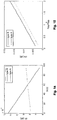
- Figs. 5 and 6 show the change of the mean wavelength of type A and B LEDs as a function of temperature. As can be seen, the wavelength shift is in the order of 1 nm for 10°C.
- Figs. 7 and 8 show the emission spectra of type A LED ( Fig. 7 ) and type B LED ( Fig. 8 ) in cold and hot state, together with the absorption spectrum of blood as well as the absorption spectrum of the rest of the near-surface body tissue.
- the device can be calibrated as follows:
- a reference signal I r ( T ) of the is determined for each operating condition or temperature T to be used later.
- the reference signal I r ( T ) corresponds to the intensity signal measured by light detector 8 if the light from light source 7 operating under the given operating condition T is reflected into said light detector by means of a body whose reflectivity does not depend on the wavelength of light source 7, i.e. whose spectral response is flat over the used wavelength range.
- the signal I ( T ) from light detector 8 (which has already been divided by correction factor ⁇ if a monitoring unit 19 as described above is used) is divided by the corresponding value of the white body response I r ( T ) at the same time or temperature T , and the inversed logarithm of the resulting quotient is a light attenuation A ( T ) according to eq. (2), at the given time or temperature.
- This value describes the optical attenuation caused by the body tissue.
- the different times t i correspond to different temperatures T i of light source 7 and therefore to different states or wavelengths of the light source.
- the typical LED has a broad emission spectrum (compared to the changes of absorptivity of blood over wavelength), and the wavelength change caused by warming up can be relatively small, thus the overall change in the spectrum has to be analyzed using integration over the involved spectral range.
- tPI is a measure of the blood concentration c or, equivalently, of blood perfusion, just as the classic perfusion index PI of Eqs. (10) and (11).
- Figure 14 and Figure 15 are sectional views of Figs. 12 and 13 , and they demonstrate the simulated response of the tPI to the changes in StO 2 and c tHb of type A and B LEDs. As it can be seen both LEDs have the similar sensitivity to the perfusion change, while the response of type B LED to oxygenation is significantly higher ( Fig. 14 ).
- a test measurement as shown in Figs. 9 and 10 was carried out.
- the tests measurement was carried out with a classical detector having two LED light sources at 568 and 798 nm as well as with a device according to the present invention using a single LED operating at 578 nm (type A LED).
- the light source of the single LED device was operated by applying current pulses of 20 mA during 100 ms with current-less pauses of 50 ms between the pulses.
- the attenuation was measured by averaging during a first period between 0 - 50 ms and by averaging during a second period between 50 -100 ms after start of each current pulse.
- the cuff was pressurized to 60 mmHg in order to create venous but not arterial occlusion.
- an increased amount of venal blood was present at the time interval between 14:50 and 14:55.
- the cuff was pressurized to 220 mmHg, thereby creating venous and arterial occlusion. This caused blood oxygenation to drop.
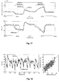
- Fig. 10 shows the classic profusion index PI, while the black curve shows the tuned profusion index tPI. As can be seen, there is an excellent match between the two values until 15:00, which indicates that tPI is as good a measure of blood perfusion as PI. This is also illustrated in Fig. 9 , which shows PI vs. tPI for the experiment of Fig. 10 , showing the strong correlation between the two parameters.
- Figs. 9 and 10 show that wavelength tuning provides an efficient means for measuring blood perfusion.
- tPI can be used to derive other parameters. For example, since blood perfusion and therefore tPI varies with the heart beat rate, recording a time series of tPI or its underlying signals allows determining the heart beat rate.
- the calibration data mentioned for step 5 can e.g. be obtained using calibration measurements, e.g. by measuring the desired parameter with a conventional reference method and by using multiple regression analysis for obtaining the calibration data.
- the attenuation signals A ( t 1 ) , A ( t 2 ) are used as independent parameters, while the values of the parameter obtained by the reference method are used as a dependent variable.
- the model used during regression can be a simple linear model, albeit more elaborate models may be used as well.
- the skin temperature T s as measured by temperature sensor 13 can be used as a further input signal (and a further independent signal during regression).
- direct measurements of the light intensity emitted by the source (LED) can be performed with the dedicated monitoring detector, for example monitoring PiN diode, placed in the vicinity of the LED in order to collect the light directly from the LED without passing through the tissue.
- the desired parameter requires repetitive measurements (such as for determining the heart beat rate)
- above steps 2 to 4 are repeated, and the blood perfusion or the raw signals or their difference is recorded for each step 4, together with the time of the measurement.
- the time series generated in this manner is then analyzed for determining the desired parameter.
- the heart beat rate for example, can be determined by calculating the distances between consecutive peaks in blood perfusion.
- the light source can also be operated under N > 2 conditions corresponding to further, different temperatures.
- a signal A is measured by means of light detector 8.
- measurements can be carried out at N > 2 times after switching the light source on. In that case there are more measurements than unknowns, which allows to further increase accuracy of the results.
- multiple regression analysis can be used to determine the calibration data.
- steps 2 to 4 can be repeated in order to sample the signals at the different phases of the heart or breath cycles and reduced the noise by averaging those measurements.
- regression of a parameterized empirical or semi-empirical model can be used as well, e.g. multiple linear regression as described in the next section.
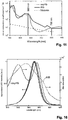
- Fig. 16 depicts three spectra of a type B LED obtained at different stages of warming up.
- the coefficients for the estimation of StO 2 from the measured attenuation signals A ( ⁇ 1 ), A ( ⁇ 2 ), A ( ⁇ 3 ) can best be found by means of multiple regression analysis.
- calibration measurements are carried out, during which oxygenation-changing procedures are applied to the user while A ( ⁇ 1 ) , A ( ⁇ 2 ), A ( ⁇ 3 ) are measured together with the value of StO 2 .
- a reference method is used for measuring the value of StO 2 .
- Multiple regression analysis can then be carried out for correlating the measured attenuation signals A ( ⁇ 1 ) , A ( ⁇ 2 ), A ( ⁇ 3 ) with StO 2 .
- time-resolved measurements can be performed, with the measurement cycle repeated continuously.
- the pulsation wave can be analyzed which allows to study the blood volume changes associated with the arterial blood.
- This approach is similar to the conventional photoplethysmography employing at least two light sources with distinctive wavelengths and allows to estimate the oxygenation of the arterial and venous blood separately.
- full-range optical reflection spectroscopy with a broad white light source can, for example, be used.
- the measured spectrum can be fitted with the known spectra of skin chromophores and the corresponding concentration can be extracted.
- the StO 2 then can be easily calculated from the concentrations.
- the device of the present invention is applied to an arm of the user for measuring the attenuation signals A ( ⁇ 1 ), A ( A 2 ), A ( ⁇ 3 ).
- the fiber end of a spectrometer is applied to the user's arm for carrying out the reference measurements of StO 2 .
- a cuff is applied to the user's arm in order to generate arterial and venous occlusion of the arm as described in the following.
- an arterial occlusion is caused, followed by a venous occlusion.
- an arterial occlusion the inflow of arterial blood and outflow of the venous blood are blocked, which results in the continuous reduction of the oxyHb content in the tissue.
- total blood volume (perfusion) might decrease or increase.
- reactive hyperemia occurs, which leads to an increase of the blood amount, and of oxyHb in particular, which leads to elevated levels of StO 2 .
- the experimental protocol consisted of the following steps with duration of approximately 4 minutes each:
- optical fibers for the reference spectroscopy were placed close to the device according to the invention in order to minimize effects of skin heterogeneity. Reference measurements were carried out in parallel with the measurements of the device.
- the skin temperature T s measured by the device was used as a fourth independent variable, and the negative logarithm the emitted intensity correction factor ⁇ measured by the monitoring device 19 was used as fifth independent variable.
- Fig. 17 shows the result of this procedure for a single measurement cycle for the determination of StO 2 and tHb concentration, both by means of the reference method (gray line) and the device (black line). As can be seen, there is an excellent correspondence of the two signals.
- the fit parameters obtained by the multiple regression analysis are shown in Fig. 19 .
- the attenuations of the wavelengths ⁇ 1 , ⁇ 2 , ⁇ 3 are the most important independent values in the model.
- the R 2 decreases only moderately to 0.602.
- the monitoring diode and skin temperature signals help to account for the variations of the outside temperature and the attachment of the sensor.
- Fig. 20 presents the performance of the alternative device using signals from the green, red and infrared diodes, as well as skin temperature.
- the present device has a higher predictive power for the tissue oxygenation than the alternative device proves that the proposed wavelength tuning is a technique well suited for measuring tissue parameters.
- red and infrared wavelengths often used in conventional clinical oximeters are not well suited for the reflectance oximetry, which is indicated by unsatisfactory performance of the alternative device using these signals. This may be due to the high range of the blood perfusion changes which is known to affect red-infrared oximetry.
- the discrepancy in the oxygenation estimation even with the best tunable model can be attributed to the non-uniformity of the perfusion and oxygen distribution in the arm and differences in the attachment of the reference fiber probe and the device.
- different pressures of the reference probe and the device can lead to a different blood amount under both sensors, as well as to different oxygenation.
- Another reason for difference may be due to the different depths probed with device and reference probe, due to slight different source-detector distances.
- the measurement should be carried out in a spectral region where the absorption of rHb and oxyHb show very different wavelength dependence, in particular where the slopes of the absorption spectra of rHb and oxyHb have opposite sign.
- the influence of oxygenation on the measured attenuation signals A ( ⁇ 1 ), A ( ⁇ 2 ), A ( ⁇ 3 ) is strongest. From Fig. 16 it can be seen that this is the case in the spectral ranges between 530 and 550 nm as well as between 560 and 580 nm.
- light source 7 should have a mean wavelength either between 530 and 550 nm or between 560 and 580 nm, and/or its spectral half-width should be not larger than approximately 20 nm, in particular not larger than 10 nm, if it emits light in the spectral range between 530 and 550 nm or not larger than approximately 20 nm, in particular not larger than 10 nm, if it emits light in the spectral range of 560 and 580 nm.
- the measurement should be carried out in a spectral region where rHb and oxyHb show absorptions having similar wavelength dependence, in particular in the neighborhood of the isosbestic points where the slopes of the absorption spectra of rHb and oxyHb are similar.
- the influence of oxygenation on the measured attenuation signals A ( ⁇ 1 ), A ( ⁇ 2 ), ... is weakest. From Fig. 16 it can be seen that this is the case in the spectral ranges 520-540 nm and 580-600 nm.
- the present device can be used for a large variety of applications. In additions to the applications mentioned so far, it can be used for hemodynamic monitoring, such as for monitoring
- Monitoring capabilities of the current approach are not limited to oxy- and reduced haemoglobins, but can be also applied to other forms of Hb, like fetal Hb, carboxyhemoglobin, carbaminohemoglobin, methemoglobin, myoglobin etc.
- Hb fetal Hb
- carboxyhemoglobin carboxyhemoglobin
- carbaminohemoglobin carbaminohemoglobin
- methemoglobin methemoglobin
- myoglobin etc etc.
- the different wavelength region of measurements or additional light sources might be required to distinguish different forms of haemoglobin. These additional sources can also have the tuning capabilities or have a fixed wavelength.
- a reflection measurement was carried out, with light source 7 and light detector 8 being arranged side by side over a surface of the tissue.
- the present invention can also be used in transmission mode, with light source 7 and light detector 8 being arranged on opposite sides of a body part, such as an ear lobe, and the light being transmitted through the body part.
Landscapes
- Health & Medical Sciences (AREA)
- Life Sciences & Earth Sciences (AREA)
- Physics & Mathematics (AREA)
- Medical Informatics (AREA)
- Surgery (AREA)
- Biophysics (AREA)
- Pathology (AREA)
- Engineering & Computer Science (AREA)
- Biomedical Technology (AREA)
- Heart & Thoracic Surgery (AREA)
- Veterinary Medicine (AREA)
- Molecular Biology (AREA)
- Public Health (AREA)
- Animal Behavior & Ethology (AREA)
- General Health & Medical Sciences (AREA)
- Optics & Photonics (AREA)
- Spectroscopy & Molecular Physics (AREA)
- Dermatology (AREA)
- Measurement Of The Respiration, Hearing Ability, Form, And Blood Characteristics Of Living Organisms (AREA)
- Investigating Or Analysing Materials By Optical Means (AREA)
Claims (18)
- Un procédé pour mesurer au moins un paramètre physiologique d'un tissu au moyen d'une source de lumière semi-conductrice (7) et d'un détecteur de lumière (8), dans lequel ledit paramètre affecte la concentration de constituants sanguins, en particulier de différentes formes d'hémoglobine, ledit procédé comprenant les étapes suivantesa) placer ladite source de lumière (7) et ledit détecteur de lumière (8) de telle sorte que ledit détecteur de lumière (8) mesure une quantité de lumière transmise par ladite source de lumière (7) à travers ledit tissu,b) faire fonctionner ladite source de lumière (7) dans un premier état dans lequel elle a une première température, et déterminer un premier signal d'atténuation de lumière au moyen dudit détecteur de lumière (8),c) faire fonctionner ladite source de lumière (7) dans un deuxième état dans lequel elle a une seconde température différente de la première température, et déterminer un deuxième signal d'atténuation de lumière au moyen dudit détecteur de lumière (8),d) déterminer ledit paramètre en utilisant ledit premier signal d'atténuation de lumière et ledit deuxième signal d'atténuation de lumière,ledit procédé comprenant en outre l'étape consistant à varier un courant à travers ladite source de lumière (7) afin de créer lesdits différents états de fonctionnement,
ledit procédé étant caractérisé par l'étape consistant à commuter ledit courant d'un premier niveau à un deuxième niveau différent et à déterminer au moins une partie desdits signaux d'atténuation à des moments différents après avoir commuté ledit courant pendant que ladite source de lumière (7) n'a pas encore atteint un équilibre thermique. - Le procédé selon la revendication 1, dans lequel au moins une partie desdits signaux d'atténuation est déterminée pendant une seconde après la commutation dudit courant, en particulier pendant 100 millisecondes.
- Le procédé selon l'une quelconque des revendications précédentes, comprenant en outre l'étape consistant à déterminer ledit paramètre en calculant une différence entre le premier et le deuxième signal d'atténuation de lumière et/ou l'étape consistant à dériver ledit paramètre à partir desdits signaux d'atténuation en utilisant des données de calibration.
- Le procédé selon l'une quelconque des revendications précédentes, dans lequel ledit paramètre est la perfusion sanguine ou tout paramètre dépendant de la perfusion sanguine.
- Le procédé selon l'une quelconque des revendications précédentes, dans lequel lesdites étapes b) et c) sont répétées pour enregistrer une série temporelle de données, dans lequel une fréquence cardiaque est déviée de ladite série temporelle de données.
- Le procédé selon l'une quelconque des revendications précédentes, comprenant l'étape consistant à faire fonctionner ladite source de lumière (7) dans N conditions où elle a N températures différentes et à mesurer un signal d'atténuation à chaque condition, où N > 2.
- Le procédé selon l'une quelconque des revendications précédentes, dans lequel, pour chaque état de fonctionnement, ledit signal d'atténuation est déterminé en mesurant un signal d'intensité au moyen dudit détecteur de lumière (8) et en divisant ledit signal d'intensité par un signal de référence (Pr), dans lequel le signal de référence (Pr) correspond à un signal d'intensité mesuré par ledit détecteur de lumière (8) si la lumière de ladite source de lumière (7) fonctionnant dans ledit état de fonctionnement est réfléchie dans ledit détecteur de lumière (8) par un corps dont le pouvoir réflectif ne dépend pas de la longueur d'onde de ladite source de lumière (7).
- Le procédé selon l'une quelconque des revendications précédentes, dans lequel ledit paramètre est déterminé en utilisant lesdits signaux d'atténuation et lesdites données de calibration, dans lequel lesdites données de calibration ont été obtenues dans une procédure de calibration, laquelle procédure de calibration comprend les étapes suivantes
effectuer une série de mesures de calibration pour différents états dudit tissu et, pour chaque mesure de calibration, enregistrer lesdits signaux d'atténuation au moyen dudit détecteur de lumière (8) et enregistrer une valeur dudit paramètre au moyen d'un procédé de référence,
utiliser une régression multiple pour déterminer lesdites données de calibration, les signaux d'atténuation enregistrés étant des variables indépendantes et les valeurs enregistrées dudit paramètre étant une variable dépendante. - Le procédé selon l'une quelconque des revendications précédentes, comprenant en outre l'étape consistant à mesurer une température de peau (Ts) dudit tissu et à utiliser ladite température de peau (Ts) pour déterminer ledit paramètre.
- Le procédé selon les revendications 8 et 9, comprenant en outre l'étape consistant à utiliser ladite température de la peau (Ts) comme variable indépendante pendant ladite régression multiple.
- Le procédé selon l'une quelconque des revendications précédentes, comprenant en outre l'étape consistant à surveiller un signal d'intensité lumineuse émis par la source de lumière (2), en particulier au moyen d'un capteur de température ou d'un capteur de lumière (19), et à mettre à l'échelle un signal provenant dudit capteur lumineux (8) au moyen dudit signal d'intensité lumineuse contrôlé (α).
- Le procédé selon les revendications 8 et 11, comprenant en outre l'étape consistant à utiliser ledit signal de surveillance comme variable indépendante pendant ladite régression multiple.
- Le procédé selon l'une quelconque des revendications précédentes, dans lequel ledit paramètre est indicatif d'un rapport entre l'hémoglobine oxygénée et l'hémoglobine non oxygénée dans ledit tissu.
- Le procédé selon l'une quelconque des revendications précédentes, dans lequel ladite source de lumière (7) a une longueur d'onde moyenne comprise entre 530 et 550 nm ou entre 560 et 580 nm, et/ou dans lequel ladite source de lumière (7) émet
entre 530 et 550 nm et a une demi-largeur spectrale non supérieure à 20 nm, en particulier non supérieure à 10 nm, ou
entre 560 et 580 nm et a une demi-largeur spectrale non supérieure à 20 nm, en particulier non supérieure à 10 nm. - Le procédé selon l'une quelconque des revendications précédentes, dans lequel ladite source de lumière (7) a une longueur d'onde moyenne comprise entre 520 et 540 nm ou entre 580 et 600 nm.
- Le procédé selon l'une quelconque des revendications précédentes, dans lequel ladite source de lumière (7) est une DEL ou une diode laser.
- Un dispositif pour mesurer in-vivo au moins un paramètre physiologique de tissu comprenant
un logement (1) à placer contre ledit tissu,
une source de lumière à semi-conducteur (7) disposée dans ledit logement,
un détecteur de lumière (8) positionné pour mesurer la lumière transmise par ladite source de lumière transmise à travers ledit tissu,
une unité de commande (14) pour faire fonctionner ladite source de lumière (7) dans un premier état dans lequel elle a une première température, et déterminer un premier signal d'atténuation au moyen dudit détecteur de lumière (8),
faire fonctionner ladite source de lumière (7) dans un deuxième état dans lequel elle a une deuxième température différente de la première température, et déterminer un deuxième signal d'atténuation au moyen dudit détecteur de lumière (8),
déterminer ledit paramètre en utilisant ledit premier signal et ledit deuxième signal d'atténuation,
dans lequel ledit dispositif est adapté pour faire varier un courant à travers ladite source de lumière (7) afin de créer lesdits différents états de fonctionnement, caractérisé en ce que ledit dispositif est adapté pour commuter ledit courant d'un premier niveau à un deuxième niveau différent et pour déterminer au moins une partie desdits signaux d'atténuation à différents moments après la commutation dudit courant pendant que ladite source de lumière (7) n'a pas encore atteint un équilibre thermique. - Le dispositif selon la revendication 17, ledit dispositif étant adapté pour exécuter le procédé selon l'une quelconque des revendications 1 à 16.
Applications Claiming Priority (1)
| Application Number | Priority Date | Filing Date | Title |
|---|---|---|---|
| PCT/CH2010/000049 WO2011103690A1 (fr) | 2010-02-26 | 2010-02-26 | Détermination optique de la perfusion sanguine et de paramètres similaires |
Publications (2)
| Publication Number | Publication Date |
|---|---|
| EP2563207A1 EP2563207A1 (fr) | 2013-03-06 |
| EP2563207B1 true EP2563207B1 (fr) | 2019-11-13 |
Family
ID=43063552
Family Applications (1)
| Application Number | Title | Priority Date | Filing Date |
|---|---|---|---|
| EP10707430.4A Active EP2563207B1 (fr) | 2010-02-26 | 2010-02-26 | Détermination optique de la perfusion sanguine et de paramètres similaires |
Country Status (3)
| Country | Link |
|---|---|
| US (1) | US9549695B2 (fr) |
| EP (1) | EP2563207B1 (fr) |
| WO (1) | WO2011103690A1 (fr) |
Cited By (1)
| Publication number | Priority date | Publication date | Assignee | Title |
|---|---|---|---|---|
| RU2822726C1 (ru) * | 2023-05-11 | 2024-07-11 | Общество с ограниченной ответственностью "ОПТИЧЕСКАЯ ДИАГНОСТИКА" | Способ диагностики расстройств периферического кровотока при сахарном диабете |
Families Citing this family (11)
| Publication number | Priority date | Publication date | Assignee | Title |
|---|---|---|---|---|
| WO2013056379A1 (fr) * | 2011-10-19 | 2013-04-25 | Biovotion Ag | Système de mesures optiques non invasives des propriétés physiologiques d'un tissu |
| US10265006B2 (en) * | 2013-01-16 | 2019-04-23 | Koninklijke Philips N.V. | Sensor for determining gas concentration |
| RU2636880C1 (ru) * | 2016-12-26 | 2017-11-28 | Общество с ограниченной ответственностью "ЦИИР ЭОС-Медика" (ООО "ЦИИР ЭОС-Медика") | Устройство для неинвазивного измерения потока микроциркуляции крови |
| JP6999385B2 (ja) * | 2017-11-30 | 2022-01-18 | 株式会社テクノ・コモンズ | 物体のデータ測定装置 |
| KR102693439B1 (ko) * | 2018-11-20 | 2024-08-07 | 삼성전자주식회사 | 스펙트럼 측정 장치, 스펙트럼의 광원 온도 변화 보정 방법, 농도 추정 장치 및 방법 |
| WO2020129989A1 (fr) * | 2018-12-21 | 2020-06-25 | 国立大学法人横浜国立大学 | Système de mesure de concentration de bilirubine |
| RU2737714C1 (ru) * | 2019-07-11 | 2020-12-02 | Акционерное общество "Елатомский приборный завод" (АО "Елатомский приборный завод") | Способ оценки микроциркуляторных нарушений в коже у пациентов с нарушениями углеводного обмена и устройство для его осуществления |
| US11172836B1 (en) * | 2019-12-05 | 2021-11-16 | Sergio Lara Pereira Monteiro | Method and means to measure heart rate with fitbit devices |
| US20230000378A1 (en) * | 2019-12-05 | 2023-01-05 | Sergio Lara Pereira Monteiro | Method and means to measure oxygen saturation/concentration in animals |
| KR102928834B1 (ko) | 2020-03-25 | 2026-02-20 | 삼성전자주식회사 | 체내 물질 성분 분석 장치 및 방법과, 임피던스 측정 장치 |
| US12678076B2 (en) * | 2022-05-09 | 2026-07-14 | Medwatch Technologies, Inc. | Health sensor using multiple light emitting diodes |
Family Cites Families (23)
| Publication number | Priority date | Publication date | Assignee | Title |
|---|---|---|---|---|
| AU465302B2 (en) | 1970-09-18 | 1975-09-25 | Richard Neason Stephens Frederick | Perfusion monitor |
| CA1037285A (fr) | 1975-04-30 | 1978-08-29 | Glenfield Warner | Appareil et procede d'oxymetrie au niveau de l'oreille |
| US4869253A (en) | 1986-08-18 | 1989-09-26 | Physio-Control Corporation | Method and apparatus for indicating perfusion and oxygen saturation trends in oximetry |
| JPS63252239A (ja) | 1987-04-09 | 1988-10-19 | Sumitomo Electric Ind Ltd | 反射型オキシメ−タ |
| CA1331483C (fr) | 1988-11-02 | 1994-08-16 | Britton Chance | Hemoglobinometre portable par l'utilisateur pour mesurer l'etat metabolique d'un patient |
| US5372136A (en) | 1990-10-06 | 1994-12-13 | Noninvasive Medical Technology Corporation | System and method for noninvasive hematocrit monitoring |
| US5277181A (en) | 1991-12-12 | 1994-01-11 | Vivascan Corporation | Noninvasive measurement of hematocrit and hemoglobin content by differential optical analysis |
| US5758644A (en) | 1995-06-07 | 1998-06-02 | Masimo Corporation | Manual and automatic probe calibration |
| DE19720300B4 (de) | 1996-06-03 | 2006-05-04 | CiS Institut für Mikrosensorik gGmbH | Elektronisches Hybrid-Bauelement und Verfahren zu seiner Herstellung |
| JP3365227B2 (ja) | 1996-10-25 | 2003-01-08 | 花王株式会社 | 皮膚の表面状態の光学的特性の測定方法及び装置 |
| US7043287B1 (en) * | 1998-05-18 | 2006-05-09 | Abbott Laboratories | Method for modulating light penetration depth in tissue and diagnostic applications using same |
| US6526298B1 (en) * | 1998-05-18 | 2003-02-25 | Abbott Laboratories | Method for the non-invasive determination of analytes in a selected volume of tissue |
| GB9907613D0 (en) | 1999-04-06 | 1999-05-26 | Huntleigh Technology Plc | Skin evaluation apparatus |
| US6928311B1 (en) | 1999-08-31 | 2005-08-09 | Nir Diagnostics Inc. | Compact device for measuring, tissue analytes |
| ATE547045T1 (de) | 2001-03-06 | 2012-03-15 | Solianis Holding Ag | Vorrichtung zur bestimmung der konzentration eines stoffes in körperflüssigkeit |
| US6802812B1 (en) * | 2001-07-27 | 2004-10-12 | Nostix Llc | Noninvasive optical sensor for measuring near infrared light absorbing analytes |
| US6862542B2 (en) | 2002-01-17 | 2005-03-01 | Charlotte-Mecklenburg Hospital | Erythema measuring device |
| DE10309747B4 (de) | 2002-03-07 | 2011-11-24 | CiS Institut für Mikrosensorik gGmbH | Auflichtsensor und Verfahren zu seiner Herstellung |
| ATE529036T1 (de) | 2003-11-27 | 2011-11-15 | Solianis Holding Ag | Techniken zur bestimmung des glucosegehaltes |
| US7251516B2 (en) | 2004-05-11 | 2007-07-31 | Nostix Llc | Noninvasive glucose sensor |
| WO2006094168A1 (fr) * | 2005-03-01 | 2006-09-08 | Masimo Laboratories, Inc. | Moniteur patient multiparametrique non invasif |
| JP4947440B2 (ja) | 2005-11-10 | 2012-06-06 | バイオボーション・アーゲー | 身体組織中のグルコース・レベルを割り出すための装置 |
| JP5628289B2 (ja) | 2009-04-17 | 2014-11-19 | バイオボーション・アーゲーBiovotion AG | グルコース決定のための広帯域フィールド応答特性測定 |
-
2010
- 2010-02-26 EP EP10707430.4A patent/EP2563207B1/fr active Active
- 2010-02-26 WO PCT/CH2010/000049 patent/WO2011103690A1/fr not_active Ceased
- 2010-02-26 US US13/581,191 patent/US9549695B2/en active Active
Non-Patent Citations (1)
| Title |
|---|
| None * |
Cited By (1)
| Publication number | Priority date | Publication date | Assignee | Title |
|---|---|---|---|---|
| RU2822726C1 (ru) * | 2023-05-11 | 2024-07-11 | Общество с ограниченной ответственностью "ОПТИЧЕСКАЯ ДИАГНОСТИКА" | Способ диагностики расстройств периферического кровотока при сахарном диабете |
Also Published As
| Publication number | Publication date |
|---|---|
| US9549695B2 (en) | 2017-01-24 |
| EP2563207A1 (fr) | 2013-03-06 |
| US20130053654A1 (en) | 2013-02-28 |
| WO2011103690A1 (fr) | 2011-09-01 |
Similar Documents
| Publication | Publication Date | Title |
|---|---|---|
| US9549695B2 (en) | Optical determination of blood perfusion and similar parameters | |
| JP4176480B2 (ja) | 非侵襲性のヘマトクリット測定値の精度を改善するための方法および装置 | |
| US6842635B1 (en) | Optical device | |
| US7239902B2 (en) | Device and method for monitoring body fluid and electrolyte disorders | |
| CA2441015C (fr) | Dispositif et procede pour controler des troubles de liquides biologiques et d'electrolyte | |
| JP5175179B2 (ja) | 改良された分光測光による血液酸素化モニタリング方法 | |
| US6456862B2 (en) | Method for non-invasive spectrophotometric blood oxygenation monitoring | |
| CA2494030C (fr) | Procede de surveillance spectrophotometrique de l'oxygenation sanguine | |
| CN103249362B (zh) | 用于血液参数的光学测量的系统、方法 | |
| US7254432B2 (en) | Method and device for non-invasive measurements of blood parameters | |
| EP1346683A2 (fr) | procédé, appareil et détecteur de détermination de la saturation fractionnaire en oxygène | |
| US20090270700A1 (en) | Non-invasive glucose sensor | |
| JP2002369814A (ja) | 非侵襲的なヘモグロビン濃度及び酸素飽和度のモニタリング方法並びに装置 | |
| Kyriacou et al. | Optical techniques for blood and tissue oxygenation | |
| JP2004290544A (ja) | 血液分析装置 | |
| Wu et al. | A compact calibratable pulse oximeter based on color filters: towards a quantitative analysis of measurement uncertainty | |
| US20160022147A1 (en) | Method and device for monitoring vital functions | |
| US11547331B1 (en) | Hydration monitor and methods of use | |
| Arimoto | Measurement of 2-D SpO2 distribution in skin tissue by multispectral imaging with depth selectivity control | |
| HK1063072B (en) | Method and apparatus for improving the accuracy of noninvasive hematocrit measurements |
Legal Events
| Date | Code | Title | Description |
|---|---|---|---|
| PUAI | Public reference made under article 153(3) epc to a published international application that has entered the european phase |
Free format text: ORIGINAL CODE: 0009012 |
|
| 17P | Request for examination filed |
Effective date: 20121218 |
|
| AK | Designated contracting states |
Kind code of ref document: A1 Designated state(s): AT BE BG CH CY CZ DE DK EE ES FI FR GB GR HR HU IE IS IT LI LT LU LV MC MK MT NL NO PL PT RO SE SI SK SM TR |
|
| RIN1 | Information on inventor provided before grant (corrected) |
Inventor name: TALARY, MARK STUART Inventor name: CADUFF, ANDREAS Inventor name: KREBS, HANS-JOACHIM Inventor name: ZAKHAROV, PAVEL |
|
| DAX | Request for extension of the european patent (deleted) | ||
| GRAP | Despatch of communication of intention to grant a patent |
Free format text: ORIGINAL CODE: EPIDOSNIGR1 |
|
| STAA | Information on the status of an ep patent application or granted ep patent |
Free format text: STATUS: GRANT OF PATENT IS INTENDED |
|
| INTG | Intention to grant announced |
Effective date: 20190606 |
|
| GRAS | Grant fee paid |
Free format text: ORIGINAL CODE: EPIDOSNIGR3 |
|
| GRAA | (expected) grant |
Free format text: ORIGINAL CODE: 0009210 |
|
| STAA | Information on the status of an ep patent application or granted ep patent |
Free format text: STATUS: THE PATENT HAS BEEN GRANTED |
|
| AK | Designated contracting states |
Kind code of ref document: B1 Designated state(s): AT BE BG CH CY CZ DE DK EE ES FI FR GB GR HR HU IE IS IT LI LT LU LV MC MK MT NL NO PL PT RO SE SI SK SM TR |
|
| REG | Reference to a national code |
Ref country code: GB Ref legal event code: FG4D |
|
| REG | Reference to a national code |
Ref country code: CH Ref legal event code: EP Ref country code: AT Ref legal event code: REF Ref document number: 1200827 Country of ref document: AT Kind code of ref document: T Effective date: 20191115 |
|
| REG | Reference to a national code |
Ref country code: DE Ref legal event code: R096 Ref document number: 602010061925 Country of ref document: DE |
|
| REG | Reference to a national code |
Ref country code: IE Ref legal event code: FG4D |
|
| REG | Reference to a national code |
Ref country code: CH Ref legal event code: NV Representative=s name: E. BLUM AND CO. AG PATENT- UND MARKENANWAELTE , CH |
|
| REG | Reference to a national code |
Ref country code: DE Ref legal event code: R082 Ref document number: 602010061925 Country of ref document: DE |
|
| REG | Reference to a national code |
Ref country code: NL Ref legal event code: MP Effective date: 20191113 |
|
| REG | Reference to a national code |
Ref country code: LT Ref legal event code: MG4D |
|
| REG | Reference to a national code |
Ref country code: CH Ref legal event code: PUE Owner name: BIOSIGNS PTE LTD., SG Free format text: FORMER OWNER: BIOVOTION AG, CH |
|
| PG25 | Lapsed in a contracting state [announced via postgrant information from national office to epo] |
Ref country code: FI Free format text: LAPSE BECAUSE OF FAILURE TO SUBMIT A TRANSLATION OF THE DESCRIPTION OR TO PAY THE FEE WITHIN THE PRESCRIBED TIME-LIMIT Effective date: 20191113 Ref country code: BG Free format text: LAPSE BECAUSE OF FAILURE TO SUBMIT A TRANSLATION OF THE DESCRIPTION OR TO PAY THE FEE WITHIN THE PRESCRIBED TIME-LIMIT Effective date: 20200213 Ref country code: PL Free format text: LAPSE BECAUSE OF FAILURE TO SUBMIT A TRANSLATION OF THE DESCRIPTION OR TO PAY THE FEE WITHIN THE PRESCRIBED TIME-LIMIT Effective date: 20191113 Ref country code: NO Free format text: LAPSE BECAUSE OF FAILURE TO SUBMIT A TRANSLATION OF THE DESCRIPTION OR TO PAY THE FEE WITHIN THE PRESCRIBED TIME-LIMIT Effective date: 20200213 Ref country code: PT Free format text: LAPSE BECAUSE OF FAILURE TO SUBMIT A TRANSLATION OF THE DESCRIPTION OR TO PAY THE FEE WITHIN THE PRESCRIBED TIME-LIMIT Effective date: 20200313 Ref country code: LT Free format text: LAPSE BECAUSE OF FAILURE TO SUBMIT A TRANSLATION OF THE DESCRIPTION OR TO PAY THE FEE WITHIN THE PRESCRIBED TIME-LIMIT Effective date: 20191113 Ref country code: GR Free format text: LAPSE BECAUSE OF FAILURE TO SUBMIT A TRANSLATION OF THE DESCRIPTION OR TO PAY THE FEE WITHIN THE PRESCRIBED TIME-LIMIT Effective date: 20200214 Ref country code: ES Free format text: LAPSE BECAUSE OF FAILURE TO SUBMIT A TRANSLATION OF THE DESCRIPTION OR TO PAY THE FEE WITHIN THE PRESCRIBED TIME-LIMIT Effective date: 20191113 Ref country code: NL Free format text: LAPSE BECAUSE OF FAILURE TO SUBMIT A TRANSLATION OF THE DESCRIPTION OR TO PAY THE FEE WITHIN THE PRESCRIBED TIME-LIMIT Effective date: 20191113 Ref country code: SE Free format text: LAPSE BECAUSE OF FAILURE TO SUBMIT A TRANSLATION OF THE DESCRIPTION OR TO PAY THE FEE WITHIN THE PRESCRIBED TIME-LIMIT Effective date: 20191113 Ref country code: LV Free format text: LAPSE BECAUSE OF FAILURE TO SUBMIT A TRANSLATION OF THE DESCRIPTION OR TO PAY THE FEE WITHIN THE PRESCRIBED TIME-LIMIT Effective date: 20191113 |
|
| REG | Reference to a national code |
Ref country code: DE Ref legal event code: R081 Ref document number: 602010061925 Country of ref document: DE Owner name: BIOSIGNS PTE LTD., SG Free format text: FORMER OWNER: BIOVOTION AG, ZUERICH, CH |
|
| PG25 | Lapsed in a contracting state [announced via postgrant information from national office to epo] |
Ref country code: HR Free format text: LAPSE BECAUSE OF FAILURE TO SUBMIT A TRANSLATION OF THE DESCRIPTION OR TO PAY THE FEE WITHIN THE PRESCRIBED TIME-LIMIT Effective date: 20191113 Ref country code: IS Free format text: LAPSE BECAUSE OF FAILURE TO SUBMIT A TRANSLATION OF THE DESCRIPTION OR TO PAY THE FEE WITHIN THE PRESCRIBED TIME-LIMIT Effective date: 20200313 |
|
| REG | Reference to a national code |
Ref country code: GB Ref legal event code: 732E Free format text: REGISTERED BETWEEN 20200528 AND 20200603 |
|
| REG | Reference to a national code |
Ref country code: GB Ref legal event code: 732E Free format text: REGISTERED BETWEEN 20200604 AND 20200610 |
|
| PG25 | Lapsed in a contracting state [announced via postgrant information from national office to epo] |
Ref country code: DK Free format text: LAPSE BECAUSE OF FAILURE TO SUBMIT A TRANSLATION OF THE DESCRIPTION OR TO PAY THE FEE WITHIN THE PRESCRIBED TIME-LIMIT Effective date: 20191113 Ref country code: EE Free format text: LAPSE BECAUSE OF FAILURE TO SUBMIT A TRANSLATION OF THE DESCRIPTION OR TO PAY THE FEE WITHIN THE PRESCRIBED TIME-LIMIT Effective date: 20191113 Ref country code: RO Free format text: LAPSE BECAUSE OF FAILURE TO SUBMIT A TRANSLATION OF THE DESCRIPTION OR TO PAY THE FEE WITHIN THE PRESCRIBED TIME-LIMIT Effective date: 20191113 Ref country code: CZ Free format text: LAPSE BECAUSE OF FAILURE TO SUBMIT A TRANSLATION OF THE DESCRIPTION OR TO PAY THE FEE WITHIN THE PRESCRIBED TIME-LIMIT Effective date: 20191113 |
|
| REG | Reference to a national code |
Ref country code: DE Ref legal event code: R097 Ref document number: 602010061925 Country of ref document: DE |
|
| REG | Reference to a national code |
Ref country code: AT Ref legal event code: MK05 Ref document number: 1200827 Country of ref document: AT Kind code of ref document: T Effective date: 20191113 |
|
| PG25 | Lapsed in a contracting state [announced via postgrant information from national office to epo] |
Ref country code: SM Free format text: LAPSE BECAUSE OF FAILURE TO SUBMIT A TRANSLATION OF THE DESCRIPTION OR TO PAY THE FEE WITHIN THE PRESCRIBED TIME-LIMIT Effective date: 20191113 Ref country code: SK Free format text: LAPSE BECAUSE OF FAILURE TO SUBMIT A TRANSLATION OF THE DESCRIPTION OR TO PAY THE FEE WITHIN THE PRESCRIBED TIME-LIMIT Effective date: 20191113 |
|
| PLBE | No opposition filed within time limit |
Free format text: ORIGINAL CODE: 0009261 |
|
| STAA | Information on the status of an ep patent application or granted ep patent |
Free format text: STATUS: NO OPPOSITION FILED WITHIN TIME LIMIT |
|
| 26N | No opposition filed |
Effective date: 20200814 |
|
| REG | Reference to a national code |
Ref country code: BE Ref legal event code: MM Effective date: 20200229 |
|
| PG25 | Lapsed in a contracting state [announced via postgrant information from national office to epo] |
Ref country code: MC Free format text: LAPSE BECAUSE OF FAILURE TO SUBMIT A TRANSLATION OF THE DESCRIPTION OR TO PAY THE FEE WITHIN THE PRESCRIBED TIME-LIMIT Effective date: 20191113 Ref country code: LU Free format text: LAPSE BECAUSE OF NON-PAYMENT OF DUE FEES Effective date: 20200226 |
|
| PG25 | Lapsed in a contracting state [announced via postgrant information from national office to epo] |
Ref country code: SI Free format text: LAPSE BECAUSE OF FAILURE TO SUBMIT A TRANSLATION OF THE DESCRIPTION OR TO PAY THE FEE WITHIN THE PRESCRIBED TIME-LIMIT Effective date: 20191113 Ref country code: AT Free format text: LAPSE BECAUSE OF FAILURE TO SUBMIT A TRANSLATION OF THE DESCRIPTION OR TO PAY THE FEE WITHIN THE PRESCRIBED TIME-LIMIT Effective date: 20191113 |
|
| PG25 | Lapsed in a contracting state [announced via postgrant information from national office to epo] |
Ref country code: IE Free format text: LAPSE BECAUSE OF NON-PAYMENT OF DUE FEES Effective date: 20200226 Ref country code: IT Free format text: LAPSE BECAUSE OF FAILURE TO SUBMIT A TRANSLATION OF THE DESCRIPTION OR TO PAY THE FEE WITHIN THE PRESCRIBED TIME-LIMIT Effective date: 20191113 |
|
| PG25 | Lapsed in a contracting state [announced via postgrant information from national office to epo] |
Ref country code: BE Free format text: LAPSE BECAUSE OF NON-PAYMENT OF DUE FEES Effective date: 20200229 |
|
| PG25 | Lapsed in a contracting state [announced via postgrant information from national office to epo] |
Ref country code: TR Free format text: LAPSE BECAUSE OF FAILURE TO SUBMIT A TRANSLATION OF THE DESCRIPTION OR TO PAY THE FEE WITHIN THE PRESCRIBED TIME-LIMIT Effective date: 20191113 Ref country code: MT Free format text: LAPSE BECAUSE OF FAILURE TO SUBMIT A TRANSLATION OF THE DESCRIPTION OR TO PAY THE FEE WITHIN THE PRESCRIBED TIME-LIMIT Effective date: 20191113 Ref country code: CY Free format text: LAPSE BECAUSE OF FAILURE TO SUBMIT A TRANSLATION OF THE DESCRIPTION OR TO PAY THE FEE WITHIN THE PRESCRIBED TIME-LIMIT Effective date: 20191113 |
|
| PG25 | Lapsed in a contracting state [announced via postgrant information from national office to epo] |
Ref country code: MK Free format text: LAPSE BECAUSE OF FAILURE TO SUBMIT A TRANSLATION OF THE DESCRIPTION OR TO PAY THE FEE WITHIN THE PRESCRIBED TIME-LIMIT Effective date: 20191113 |
|
| REG | Reference to a national code |
Ref country code: CH Ref legal event code: U11 Free format text: ST27 STATUS EVENT CODE: U-0-0-U10-U11 (AS PROVIDED BY THE NATIONAL OFFICE) Effective date: 20260301 |
|
| PGFP | Annual fee paid to national office [announced via postgrant information from national office to epo] |
Ref country code: GB Payment date: 20260219 Year of fee payment: 17 |
|
| PGFP | Annual fee paid to national office [announced via postgrant information from national office to epo] |
Ref country code: DE Payment date: 20260225 Year of fee payment: 17 |
|
| PGFP | Annual fee paid to national office [announced via postgrant information from national office to epo] |
Ref country code: FR Payment date: 20260223 Year of fee payment: 17 |
|
| PGFP | Annual fee paid to national office [announced via postgrant information from national office to epo] |
Ref country code: CH Payment date: 20260301 Year of fee payment: 17 |