EP2563260B1 - Instrument chirurgical malléable pilotable - Google Patents
Instrument chirurgical malléable pilotable Download PDFInfo
- Publication number
- EP2563260B1 EP2563260B1 EP11719933.1A EP11719933A EP2563260B1 EP 2563260 B1 EP2563260 B1 EP 2563260B1 EP 11719933 A EP11719933 A EP 11719933A EP 2563260 B1 EP2563260 B1 EP 2563260B1
- Authority
- EP
- European Patent Office
- Prior art keywords
- body portion
- lead wires
- surgical instrument
- sleeve
- tracking device
- Prior art date
- Legal status (The legal status is an assumption and is not a legal conclusion. Google has not performed a legal analysis and makes no representation as to the accuracy of the status listed.)
- Active
Links
Images


Classifications
-
- A—HUMAN NECESSITIES
- A61—MEDICAL OR VETERINARY SCIENCE; HYGIENE
- A61B—DIAGNOSIS; SURGERY; IDENTIFICATION
- A61B34/00—Computer-aided surgery; Manipulators or robots specially adapted for use in surgery
- A61B34/20—Surgical navigation systems; Devices for tracking or guiding surgical instruments, e.g. for frameless stereotaxis
-
- A—HUMAN NECESSITIES
- A61—MEDICAL OR VETERINARY SCIENCE; HYGIENE
- A61B—DIAGNOSIS; SURGERY; IDENTIFICATION
- A61B17/00—Surgical instruments, devices or methods
- A61B17/24—Surgical instruments, devices or methods for use in the oral cavity, larynx, bronchial passages or nose; Tongue scrapers
-
- A—HUMAN NECESSITIES
- A61—MEDICAL OR VETERINARY SCIENCE; HYGIENE
- A61B—DIAGNOSIS; SURGERY; IDENTIFICATION
- A61B17/00—Surgical instruments, devices or methods
- A61B2017/00831—Material properties
- A61B2017/00946—Material properties malleable
-
- A—HUMAN NECESSITIES
- A61—MEDICAL OR VETERINARY SCIENCE; HYGIENE
- A61B—DIAGNOSIS; SURGERY; IDENTIFICATION
- A61B34/00—Computer-aided surgery; Manipulators or robots specially adapted for use in surgery
- A61B34/20—Surgical navigation systems; Devices for tracking or guiding surgical instruments, e.g. for frameless stereotaxis
- A61B2034/2046—Tracking techniques
- A61B2034/2051—Electromagnetic tracking systems
-
- A—HUMAN NECESSITIES
- A61—MEDICAL OR VETERINARY SCIENCE; HYGIENE
- A61B—DIAGNOSIS; SURGERY; IDENTIFICATION
- A61B90/00—Instruments, implements or accessories specially adapted for surgery or diagnosis and not covered by any of the groups A61B1/00 - A61B50/00, e.g. for luxation treatment or for protecting wound edges
- A61B90/39—Markers, e.g. radio-opaque or breast lesions markers
- A61B2090/397—Markers, e.g. radio-opaque or breast lesions markers electromagnetic other than visible, e.g. microwave
- A61B2090/3975—Markers, e.g. radio-opaque or breast lesions markers electromagnetic other than visible, e.g. microwave active
-
- A—HUMAN NECESSITIES
- A61—MEDICAL OR VETERINARY SCIENCE; HYGIENE
- A61B—DIAGNOSIS; SURGERY; IDENTIFICATION
- A61B90/00—Instruments, implements or accessories specially adapted for surgery or diagnosis and not covered by any of the groups A61B1/00 - A61B50/00, e.g. for luxation treatment or for protecting wound edges
- A61B90/39—Markers, e.g. radio-opaque or breast lesions markers
- A61B2090/3983—Reference marker arrangements for use with image guided surgery
-
- A—HUMAN NECESSITIES
- A61—MEDICAL OR VETERINARY SCIENCE; HYGIENE
- A61M—DEVICES FOR INTRODUCING MEDIA INTO, OR ONTO, THE BODY; DEVICES FOR TRANSDUCING BODY MEDIA OR FOR TAKING MEDIA FROM THE BODY; DEVICES FOR PRODUCING OR ENDING SLEEP OR STUPOR
- A61M1/00—Suction or pumping devices for medical purposes; Devices for carrying-off, for treatment of, or for carrying-over, body-liquids; Drainage systems
- A61M1/84—Drainage tubes; Aspiration tips
-
- A—HUMAN NECESSITIES
- A61—MEDICAL OR VETERINARY SCIENCE; HYGIENE
- A61M—DEVICES FOR INTRODUCING MEDIA INTO, OR ONTO, THE BODY; DEVICES FOR TRANSDUCING BODY MEDIA OR FOR TAKING MEDIA FROM THE BODY; DEVICES FOR PRODUCING OR ENDING SLEEP OR STUPOR
- A61M2205/00—General characteristics of the apparatus
- A61M2205/35—Communication
- A61M2205/3546—Range
- A61M2205/3561—Range local, e.g. within room or hospital
-
- A—HUMAN NECESSITIES
- A61—MEDICAL OR VETERINARY SCIENCE; HYGIENE
- A61M—DEVICES FOR INTRODUCING MEDIA INTO, OR ONTO, THE BODY; DEVICES FOR TRANSDUCING BODY MEDIA OR FOR TAKING MEDIA FROM THE BODY; DEVICES FOR PRODUCING OR ENDING SLEEP OR STUPOR
- A61M2205/00—General characteristics of the apparatus
- A61M2205/35—Communication
- A61M2205/3576—Communication with non implanted data transmission devices, e.g. using external transmitter or receiver
Definitions
- the present disclosure relates generally to a navigated malleable surgical instrument.
- Surgical procedures can be performed on anatomies such as the human anatomy for providing a therapy to the anatomy.
- One area of surgery includes procedures performed on facial cavities of a patient such as on the ear, nose or throat (ENT).
- a surgical instrument such as a suction device may be inserted into such a cavity to perform a procedure for example.
- a therapy such as a suction procedure
- tracking devices In navigation systems, instruments are provided with tracking devices. Sometimes, however, such tracking devices can be difficult to manipulate or cumbersome to the instrument. In other instances, the tracking devices can be positioned in a handle or proximal region of the instrument such that if the distal tip moves or is moved relative to the handle, the distal tip can no longer be accurately tracked.
- WO 2006/116597 A2 Methods and devices for performing procedures within the ear, nose, throat and paranasal sinuses are disclosed in WO 2006/116597 A2 .
- a method and apparatus for tracking catheters are disclosed in EP 0425319 A2 .
- Vessel position and configuration imaging apparatus and methods are disclosed in US 2008/171934 A1 .
- a surgical instrument can include an elongated body portion, a tracking device, and a handle portion.
- the elongated body portion can include a proximal end, a distal end, and an inner diameter defining a first internal flow passage between the proximal and distal ends.
- the body portion can be formed from a malleable metallic material such that the body portion can be bent between the proximal and distal ends from a first configuration to a second bent configuration and maintain the bent configuration.
- the tracking device can be positioned adjacent or near the distal end and can be adapted to cooperate with a navigation system to track a distal tip of the instrument.
- the handle portion can be coupled to the proximal end of the body portion and can include a second internal flow passage in fluid communication with the first internal flow passage.
- the tracking device can include at least a pair of lead wires wound around the body portion from the tracking device to the handle portion, the wound lead wires can be configured to conform to the bent configuration of the body portion such that they do not strain or break during bending of the body portion.
- a surgical instrument in another form, can include an elongated tubular body portion, a tubular insert portion, and a sleeve.
- the tubular body portion can have a proximal end, a distal end, and an inner diameter defining a first internal flow passage between the proximal and distal ends.
- the body portion can be formed from a malleable metallic material such that the body portion can be bent between the proximal and distal ends from a first configuration to a second bent configuration and maintain the bent configuration.
- the tubular insert portion can have a proximal end and a distal tip, the proximal end of the insert portion can be received in the inner diameter of the distal end of the body portion, and the insert portion can be formed of a rigid, non-bendable material.
- the sleeve can be configured to be received over the insert portion and extend from the distal end thereof partially towards the proximal end.
- the instrument can further include a tracking device and a handle portion. The tracking device can be coupled to the sleeve adjacent to the distal tip of the insert, and can be adapted to cooperate with a navigation system to track the distal tip of the instrument.
- the handle portion can be coupled to the proximal end of the body portion and can include a second internal flow passage in fluid communication with the first internal flow passage.
- the tracking device can include at least a pair of lead wires helically wound around the body portion at an acute angle relative to a longitudinal axis of the body portion, where the helically wound pair of lead wires can be configured to conform to the bent configuration of the body portion such that they do not strain or break during bending of the body portion.
- a flexible outer layer can cover the body portion, sleeve, insert and tracking device.
- FIG. 1 is a diagram schematically illustrating an overview of an image-guided navigation system 10 for use in the non-line-of-site navigating of a surgical instrument 100, such as a navigable malleable suction device or suction instrument, according to various exemplary embodiments of the present disclosure.
- exemplary navigation systems include those disclosed in U.S. Pat. No. 7,366,562, issued on April 29, 2008 to John H. Dukesherer et al. and U.S. Pat. App. Pub No. 2008/0132909, published June 5, 2008, to Bradley A. Jascob et al.
- Commercial navigation systems include the StealthStation® AxiEMTM Surgical Navigation System sold by Medtronic Navigation, Inc. having a place of business in Louisville, Colorado, USA. It should be appreciated that while the navigation system 10 and suction instrument 100 are generally described in connection with an ear, nose and throat (ENT) procedure, navigation system 10 and suction instrument 100 can be used in various other appropriate procedures.
- Navigation system 10 can be used to track a location of suction instrument 100, including a distal tip or end thereof, as will be described herein.
- Navigation system 10 can generally include an optional imaging system 20, such as a fluoroscopic X-ray imaging device configured as a C-arm 24 and an image device controller 28.
- the C-arm imaging system 20 can be any appropriate imaging system, such as a digital or CCD camera, which are well understood in the art.
- Image data obtained can be stored in the C-arm controller 28 and sent to a navigation computer and/or processor controller or work station 32 having a display device 36 to display image data 40 and a user interface 44.
- the work station 32 can also include or be connected to an image processor, navigation processor, and a memory to hold instruction and data.
- the work station 32 can include an optimization processor that assists in a navigated procedure. It will also be understood that the image data is not necessarily first retained in the controller 28, but may also be directly transmitted to the workstation 32. Moreover, processing for the navigation system and optimization can all be done with a single or multiple processors all of which may or may not be included in the work station 32.
- the work station 32 provides facilities for displaying the image data 40 as an image on the display device 36, saving, digitally manipulating, or printing a hard copy image of the received image data.
- the user interface 44 which may be a keyboard, mouse, touch pen, touch screen or other suitable device, allows a physician or user 50 to provide inputs to control the imaging device 20, via the C-arm controller 28, or adjust the display settings of the display device 36.
- the navigation system 10 can further include a tracking system, such as an electromagnetic (EM) tracking system 60.
- the discussion of the EM tracking system 60 can be understood to relate to any appropriate tracking system.
- the EM tracking system 60 can include a localizer, such as a coil array 64 and/or second coil array 68, a coil array controller 72, a navigation probe interface 80, and the trackable suction instrument 100.
- Instrument 100 includes an instrument tracking device or devices 84, as will be discussed herein.
- the tracking device 84 includes an electromagnetic coil to sense a field produced by the localizing coil arrays 64, 68 and provide information to the navigation system 10 to determine a location of the tracking device 84.
- the navigation system 10 can then determine a position of a distal tip of the suction instrument 100 to allow for navigation relative to the patient 34 and patient space.
- the EM tracking system 60 can use the coil arrays 64, 68 to create an electromagnetic field used for navigation.
- the coil arrays 64, 68 can include a plurality of coils that are each operable to generate distinct electromagnetic fields into the navigation region of the patient 34, which is sometimes referred to as patient space.
- Representative electromagnetic systems are set forth in U.S. Patent No. 5,913,820 , entitled “Position Location System,” issued June 22, 1999 and U.S. Patent No. 5,592,939 , entitled “Method and System for Navigating a Catheter Probe," issued January 14, 1997
- the coil arrays 64, 68 can be controlled or driven by the coil array controller 72.
- the coil array controller 72 can drive each coil in the coil arrays 64, 68 in a time division multiplex or a frequency division multiplex manner. In this regard, each coil may be driven separately at a distinct time or all of the coils may be driven simultaneously with each being driven by a different frequency.
- electromagnetic fields are generated within the patient 34 in the area where the medical procedure is being performed, which is again sometimes referred to as patient space.
- the electromagnetic fields generated in the patient space induce currents in the tracking device 84 positioned on or in the suction instrument 100.
- These induced signals from the tracking device 84 can be delivered to the navigation probe interface 80 and subsequently forwarded to the coil array controller 72.
- the navigation probe interface 80 can also include amplifiers, filters and buffers to directly interface with the tracking device 84 in the instrument 100.
- the tracking device 84, or any other appropriate portion may employ a wireless communications channel, such as that disclosed in U.S. Patent No. 6,474,341 , entitled "Surgical Communication Power System," issued November 5, 2002, as opposed to being coupled directly to the navigation probe interface 80.
- the tracking system 60 if it is using an electromagnetic tracking assembly, essentially works by positioning the coil arrays 64, 68 adjacent to the patient 32 to generate a magnetic field, which can be low energy, and generally referred to as a navigation field. Because every point in the navigation field or patient space is associated with a unique field strength, the electromagnetic tracking system 60 can determine the position of the instrument 100 by measuring the field strength at the tracking device 84 location.
- the coil array controller 72 can receive the induced signals from the tracking device 84 and transmit information regarding a location, where location information can include both x, y, and z position and roll, pitch, and yaw orientation information, of the tracking device 84 associated with the tracked suction instrument 100. Accordingly, six degree of freedom (6 DOF) information can be determined with the navigation system 10.
- 6 DOF six degree of freedom
- the navigated malleable surgical instrument 100 can be used for suction, including fluid and tissue removal in ENT procedures. It should be appreciated, however, that the navigated malleable surgical instrument 100 can be used in various other surgical procedures as may be desired and can be provided in the form of a malleable or flexible endoscope, a malleable or flexible catheter, and/or a malleable cannula. Thus, while the following description continues with reference to a navigated malleable suction instrument 100, the discussion is also applicable to the surgical instruments discussed above.
- Suction instrument 100 includes a tube assembly 110, a handle assembly 114 and a tracking sensor arrangement 118. Suction instrument 100 can be configured for a single use such that it would be disposed after such use.
- the tube assembly 110 includes a malleable elongated tubular body 126 and an insert portion 130.
- the tubular body 126 can include an outer diameter 134 and an inner diameter 138 and has a first end 142 coupled to the handle assembly 114 and a second opposite end 148 configured to receive insert portion 130, as shown in Figure 6 .
- the second end 148 can include an internal annular recess 152 having an inner diameter 156 greater than the inner diameter 138 of the remaining portion of body 126, as also shown in Figure 6 .
- the malleable elongated body 126 can be formed from various aluminum alloys, such as AL 3003-O, and various stainless steel alloys, such as 304 annealed, such that it is malleable to facilitate being bent or formed into various configurations and retaining the bent or formed configuration, as will be discussed herein.
- the body 126 can also be provided in various lengths and diameters, including 7, 9 and 12 French (2.33, 3 and 9 mm) diameters.
- Insert portion 130 is configured to provide non-malleable support for at least the tracking sensor 84.
- Insert portion 130 can include an outer diameter 160 substantially equal to the inner diameter 156 of annular recess 152, and an inner diameter 164 substantially equal to the inner diameter 138 of malleable elongated body 126, as also shown in Figure 6 .
- the substantially equal inner diameters 138, 164 can provide for a substantially constant flow path 166 for suction. It should be appreciated, however, that the inner diameters 138, 164 can also be provided with varying dimensions.
- Insert portion 130 includes a first end 172 and a second opposite end 176. The first end 172 of the insert portion 130 can be received in annular recess 152, as shown in Figure 6 .
- Insert portion includes a rigid construction to facilitate receiving and housing tracking device 84, as will be described herein.
- insert portion 130 can be formed or manufactured from stainless steel or other biocompatible rigid materials such that insert portion 130 is not malleable like elongated body 126.
- the insert portion can also include an exemplary axial length of approximately 10 mm.
- Insert portion 130 includes a sleeve 190 received on an exterior thereof, as shown in Figures 5 and 6 .
- Sleeve 190 can include an inner diameter 194 substantially equal to the outer diameter of insert portion 130, and an outer diameter 198 substantially equal to the outer diameter 134 of body 126. It should be appreciated that sleeve 190 can also be configured with different diameters relative to body 126.
- Sleeve 190 extends over a portion of insert 130 from the first end 172 of the insert portion 130 towards the second end, as shown in Figure 6 . In one exemplary configuration, sleeve 190 can extend from the first end 172 and contact the first end 142 of body 126 when the insert portion 130 is coupled to annular recess 152 of body 126.
- sleeve 190 can extend from the first end 172 of body portion 130 in a similar manner as discussed above, but can stop short of the first end 142 of body 126, as shown in Figure 6 .
- Sleeve 190 can be fixed to insert portion 130, and insert portion 130 can be fixed to annular recess 152 with an appropriate adhesive.
- Sleeve 190 can be formed of a polymeric material or other suitable materials.
- Sleeve 190 can also include a first end 220 configured to substantially align with the second end 176 of insert 130.
- the first end 220 can include a rounded or chamfered blunt distal tip 222 such that it can be placed against surrounding tissue during a suction procedure without cutting or damaging such tissue.
- sleeve 190 includes a plurality of flattened sections 206 configured to facilitate receiving and supporting the tracking sensor arrangement 118, as will be described herein.
- sleeve 190 can include at least three flattened sections 206 configured to attachably receive tracking device 84.
- the tracking device 84 can include three coil assemblies 214, as will be described herein.
- the three coil assemblies 214 can each include a cylindrical configuration as shown in Figures 4 and 5 , having an overall axial length of approximately 1.5 mm to 2 mm, an overall diameter of approximately 0.3 to 0.5 mm, and a plurality of wire windings wound along a cylindrical base to form the cylindrical configuration.
- the plurality of windings can form the coil assembly 214 having the generally uniform cylindrical configuration, as generally shown in Figure 5 .
- Each flattened section 206 includes a slot or depression 218 formed therein and configured to receive a corresponding coil assembly 214, as shown for example in Figures 5 and 6 .
- Each slot 218 can be formed in the corresponding flattened section 206 at a 0 to 90 degree angle to a longitudinal axis 208 of the tube assembly 110. In one exemplary configuration, each slot 218 can be formed at a 45 or 55 degree angle to longitudinal axis 208, as shown in Figure 5 .
- Each of the three flattened sections 206 can be positioned equidistantly or 120 degrees around a circumference of sleeve 190 so that the three coil assemblies 214 are therefore likewise positioned equidistantly around the circumference of sleeve 90, as also generally shown in Figures 4-6 .
- the coil assemblies can also be coupled to the sleeve without the flattened sections 206, and can be aligned at different orientations relative to the longitudinal axis, including parallel thereto.
- the sleeve 190 can include an outer surface with a circular shape in cross-section configured to receive the coil assemblies 214.
- the coil assemblies 214 can include three coil assemblies as described above that cooperate with the navigation system 10 such that 6 DOF tracking information can be determined. It should be appreciated, however, that two coil assemblies 214 could also be used in conjunction with navigation system 10 such that 6 DOF tracking information can also be determined. In a configuration where three coil assemblies 214 are utilized, two of the three coil assemblies can be positioned at an angle relative to the longitudinal axis 208 with the third coil assembly being positioned at an angle relative to the longitudinal axis 208 or parallel thereto. The three coil assemblies 214 can also each be positioned at an angle relative to each other.
- an exemplary angle of the three coil assemblies 214 relative to the longitudinal axis 208 can be 45 or 55 degrees, which also provides for optimal packaging and spacing of the coil assemblies circumferentially around sleeve 190. It should be appreciated that while an angle of 45 or 55 degrees has been discussed, other angles could be utilized with coil assemblies 214 and instrument 100 as may be required. It should also be appreciated, as discussed above, that the coil assemblies could be positioned parallel or perpendicular to the longitudinal axis 208.
- the two coil assemblies can similarly be positioned equidistant or 180 degrees spaced around an outer perimeter of sleeve 190, as well as can each be positioned at an angle relative to each other and at an angle relative to the longitudinal axis 208 of the tube assembly 110.
- the two coil assemblies can also cooperate with navigation system 10 such that 6 DOF tracking information can be determined.
- the two coil assemblies 214 can be positioned at an angle of about 0 to 90 degrees, including about 45 degrees relative to longitudinal axis 208 of the tube assembly 210.
- Coil assemblies 214A and 214B having alternative winding configurations are illustrated operatively associated with an exemplary tubular structure 223 of an exemplary instrument not forming part of the present invention.
- Coil assemblies 214A and 214B can each include an overall non-linear shape as compared to the overall cylindrical configuration of coils assemblies 214 shown in Figure 5 .
- Coil assembly 214A can include a central arcuate depression or concavity 224 such that the depression 224 has a smaller outer diameter than opposed ends 225 of the plurality of windings, as generally shown in Figure 8 .
- coil assembly 214A can provide an ability to maximize an amount of coil windings on a base wire while working towards minimizing an overall outer dimension or size of an instrument.
- coil assembly 214A is shown in Figure 8 with the arcuate depression 224 substantially conforming to an outer surface 226 of the tubular structure 223 such that the coil assembly or assemblies 214A essentially nest around the outer surface 226 of the tubular structure.
- a gap or space 221 on either end of the coil can include additional windings without effectively increasing the overall outer diameter of the entire assembly. This can allow for greater or stronger sensitivity in the navigated space.
- coil assembly 214B can include an overall arcuate convex shape 227 configured to conform to and nest within an inner diameter 229 of the exemplary tubular structure. Similar to coil assembly 214A, such a configuration can provide for maximizing an amount of windings on the base wire while also working towards minimizing the inner diameter 229 of the tubular structure 223 that would be required to receive one or more coil assemblies 214B.
- Tracking sensor arrangement 118 can include the tracking device 84 having the two or three coil assemblies 214, as well as a first set of lead wires 228, a printed circuit board 232 and a second set of lead wires 236.
- the first set of lead wires 228 can include a pair of lead wires 228A for each coil assembly 214, as generally shown in Figure 6 .
- Each respective pair of lead wires 228A can be routed to a first end of a respective pair of connections 240 on printed circuit board 232. It should be appreciated that while tracking device 84 is described as having three coil assemblies, more or less coil assemblies can be utilized as may be desired or required depending on, for example, characteristics of the navigation system being utilized as well as the number of degrees of freedom desired.
- Printed circuit board 232 can include a flexible backing 244 such that it can readily conform to the contour of an outer surface of the body 126, as shown for example in Figure 4 .
- the flexible printed circuit board 232 can wrap entirely or partially around a perimeter of the body 126 and can be positioned adjacent the second end 148 of body 126, as generally shown in Figures 5 and 6 .
- the insert portion 130 in its inserted position shown in Figure 6 , can be under all or substantially all of the printed circuit board 232.
- the rigid insert portion 130 can thus prevent the malleable body 126 from bending or flexing in a region of the printed circuit board 232.
- the printed circuit board can be an integral part of sleeve 190.
- the second set of lead wires can include three respective pairs of wires 236A, 236B, 236C, as generally shown in Figure 5 with reference to the partial exploded view in Figure 5A .
- Figures 2-5 , 6-7 and 10 show the second set of lead wires 236 as one element, this is for illustration purposes only and it should be understood that the second set of lead wires shown in Figures 2-5 , 6-7 and 10 include the three respective pairs of lead wires 236A-C, as shown in Figure 5A .
- Each pair of lead wires 236A-C can be twisted together and positioned adjacent each other, as also shown in Figure 5A .
- the twisted pairs 236A-C of wires can reduce electrical interference or cross-talk between each pair of adjacent lead wires.
- Each pair of lead wires can be connected to a single coil assembly 214.
- the lead wires can also include a Teflon coating or other appropriate lubricous or friction reducing coating on an outer surface thereof.
- Each pair of lead wires 236A-C can be coupled to an opposite end of respective connectors 240 on printed circuit board 232. It should be appreciated that the lead wires 228 could alternatively extend up the body 126 as a twisted pair of lead wires without the use of printed circuit board 232, or could extend up to and be terminated directly to the respective twisted pair of lead wires 236.
- the wires 236 can be wound around the outside of body 126 at an angle ⁇ relative to the longitudinal axis 208 of approximately 0 to 85 degrees, including about 30 degrees, as generally shown in Figures 5 and 5A .
- Each revolution of the wires 236 around body 126 can be spaced apart from each other by a distance D of approximately 2 to 45 mm, including about 5 mm, as shown with reference to Figure 5 .
- the range can include from about 15 - 45 mm.
- the helical winding of the wires 236 at an acute angle relative to the longitudinal axis along with the relatively close spacing of the wires and the Teflon coating facilitate being able to bend the malleable body 126 at significant angles, including beyond ninety degrees, without breaking or otherwise damaging the wires 236, as will be discussed herein.
- the wires 236 can also be positioned along body 126 in a single revolution from the printed circuit board 232 or the tracking device 84 to the second end 148.
- the revolution spacing can be from about 2 mm to a length of the body 126.
- the wires 236 can also be positioned along body 126 from the printed circuit board 232 to the second end 148 without being wound around body 136 which, however, does not form part of the present invention.
- the wires can be routed into slots 254 in handle assembly 114 and connected to respective lead wires of a cable connector assembly 258, as generally shown in Figure 7 .
- the cable connector assembly 258 can be connected to the navigation probe interface 80, as generally shown in Figure 1 .
- the handle assemble 114 can include two half sections 264, with one half section being shown in Figure 7 for illustration purposes.
- the tube assembly 110 can include a polymeric outer heat shrink 272 covering the entire assembly, as shown in the cross-sectional view of Figure 6 .
- the heat shrink 272 can cover the elongated body 126, the insert portion 130, and the sensor arrangement 118 including the wires helically wound along the body 126.
- the heat shrink 272 can provide an outer covering or shell over the tube assembly 110 and sensor arrangement 118 while providing sufficient flexibility for both bending of the body 126 and slight relative movement of the helically wound wires 236 as a result of the bending.
- the wires can be moveably captured between the heat shrink and the tubular body.
- the heat shrink covering can also serve as an electric isolation barrier. It should be appreciated that while the heat shrink covering is only shown in Figure 6 , it has not been shown in the other various views for clarification purposes only to better illustrate the sensor arrangement 118 and routing of wires 236. In this regard, it should be understood that the heat shrink 272 can cover the tube assembly 110 and sensor arrangement 118 shown in Figures 2-10 .
- the handle assembly 114 can include multiple components, such as for example two halves, with one of the halves shown in Figure 7 receiving the first end of the suction tube assembly 110 in fluid communication with a suction passage 280 formed therein.
- the suction passage 280 can terminate at a connector 284 protruding from a proximal end of the handle ( Figures 2 and 3 ) and can be configured to receive a suction hose or other arrangement in fluid communication with a suction source (not shown).
- the other half of handle assembly 114 can connected and an adhesive can be used to bond the handle halves together to form the handle as shown in Figures 2 and 3 .
- handle assembly 114 can include a suction adjustment feature 290 which can be in the form of a bore 292 extending from an outer surface 294 of the handle assembly 114 and into fluid communication with the suction passage 280.
- a surgeon or user 50 of the instrument 100 can place their thumb or another object over the bore 292 to vary an opening of the bore 292 and thus vary an amount of suction pressure realized in the flow path or passage 166. For example, if the bore 292 is left completely open or uncovered, a majority if not all of the suction will be through the bore 292 and not the first end 172 of insert portion 130.
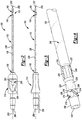
- the malleable elongated body 126 can be bent into various configurations, as generally shown by the exemplary configurations 300A-D.
- the malleable nature of body 126 can provide the ability for body 126 to be bent into such various configurations without kinking and can maintain the various configurations until bent or shaped into another configuration.
- malleable body 126 can be bent or shaped as discussed above without require additional tools, such as a mandrel to facilitate the bending. This is advantageous, for example, in that a surgeon can bend body 126 multiple times by hand during a procedure in close proximity to the patient without having to resort to additional tools or other equipment to facilitate the bending while performing the procedure.
- the helically wound configuration of wires 236 along with the Teflon coating provides for the ability to bend malleable body 126 at various angles including through ninety degrees without breaking the wires. More specifically, by winding wires 236 helically around body 126 at an angle relative to the longitudinal axis and at a close proximity to each other, the wound wires conform to the bent shape and move or flex axially with the bent tube such that they do not strain and/or break during the bending.
- the Teflon coating provides added lubricity for the wires to have relative motion between the tube and the outer shrink coating 272 during bending.
- the distal tip 222 of the suction instrument can be tracked to provide substantially accurate position data for the distal tip of suction instrument 100 when out of a line of sight in a body cavity of patient 34.
- This is particularly useful for the malleable suction instrument 100 because, for example, the tip can be bent or moved relative to the handle and still be tracked.
- the tracking device was in the handle (such as in a hind tracked system) and the body 126 was subsequently bent or shaped, the navigation system would no longer be able to accurately track the position of the distal tip.
- the present teaching provide a tip tracked malleable suction instrument that can be bent or shaped into various configurations as may be required during a procedure, and the distal tip can be accurately tracked in any of the various bent positions.
- the patient 34 can be positioned on an operating table or other appropriate structure and appropriate image data of a patient or navigation space can be obtained, such as an ENT area.
- the image data can be registered to the navigation space as is known in the art.
- the surgeon 50 can determine a shape of the malleable suction instrument 100 to reach a target site and bend the suction instrument 100 to the determined shape where instrument 100 retains the bent shape, as discussed above.
- the bent or shaped surgical instrument 100 can then be guided to the target site with an icon representing the position of the distal tip of instrument 100 being superimposed on the image data.
- the icon can show the tracked relative position of the distal tip as instrument 100 is navigated to the target site.
- the surgeon determines that the shaped configuration will need to be altered, the surgeon can bend and/or reshape the instrument 100 to a newly shaped configuration and proceed again as discussed above.
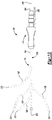
- tracking device 84' can include two or three wrapped coil assemblies 214' that can be used in place of the coil assemblies 214.
- Coil assemblies 214' can be wrapped around sleeve 190 proximate the distal tip 222.
- the coil assemblies 214' can be individually wrapped around sleeve 190 in an overlapping manner with a wrap axis having a non-normal and non-parallel angle to longitudinal axis 208.
- coil assemblies 214' can be wrapped around sleeve 190 at an angle relative to each other and longitudinal axis 208.
- coil assemblies 214' can be wrapped around sleeve 190 and spaced axially apart from each other.
- a further discussion of the coil assemblies 214' can be found in U.S. Application Serial No. 12/770,181, filed on April 29, 2010 and entitled "Method and Apparatus for Surgical Navigation"
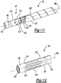
- Tracking device 84" can also be used in place of tracking device 84 and can include a plurality of oval coil assemblies 214" positioned about sleeve 190 proximate distal tip 222.
- two to four coil assemblies 214" can be positioned about sleeve 190 proximate distal tip 222.
- four coil assemblies 214" can be circumferentially spaced around sleeve 190 proximate distal tip 222, and an axial coil 304 can be positioned proximally of coil assemblies 214", as shown in Figure 12 .
- two oval coil assemblies 214" can be provided with the axial coil 304.
- the two coil assemblies 214" can also include two pair of coil assemblies 214" provided with the axial coil 304.
- the coil assemblies 214" can be formed in various selected shapes, such as elliptical, circular, or oval.
- the axial coil 304 can be concentric with and wrapped around an outer surface of sleeve 190 or body 126, as shown in Figure 12 .
- a further discussion of coil assemblies 214" and axial coil 304 can be found in U.S. Application Serial No. 13/016,740, filed on January 28, 2011 and entitled "Method and Apparatus for Image-Based Navgation"
Landscapes
- Health & Medical Sciences (AREA)
- Surgery (AREA)
- Life Sciences & Earth Sciences (AREA)
- Engineering & Computer Science (AREA)
- Medical Informatics (AREA)
- General Health & Medical Sciences (AREA)
- Biomedical Technology (AREA)
- Heart & Thoracic Surgery (AREA)
- Nuclear Medicine, Radiotherapy & Molecular Imaging (AREA)
- Molecular Biology (AREA)
- Animal Behavior & Ethology (AREA)
- Veterinary Medicine (AREA)
- Public Health (AREA)
- Robotics (AREA)
- Dentistry (AREA)
- Oral & Maxillofacial Surgery (AREA)
- Otolaryngology (AREA)
- Pulmonology (AREA)
- Surgical Instruments (AREA)
Claims (13)
- Instrument chirurgical (100) comprenant :une partie de corps allongée (126) ayant une extrémité proximale et une extrémité distale, la partie de corps ayant un diamètre interne définissant un premier passage d'écoulement interne entre les extrémités proximale et distale, la partie de corps étant formée d'un matériau métallique malléable de sorte que la partie de corps peut être pliée entre les extrémités proximale et distale d'une première configuration à une seconde configuration pliée et maintenir la configuration pliée ;un dispositif de suivi (84) positionné de manière adjacente à l'extrémité distale de la partie de corps et adapté pour coopérer avec un système de navigation (10) afin de suivre un bout distal de l'instrument ;dans lequel le dispositif de suivi comprend une bobine électromagnétique (214), etune partie de poignée (114) couplée à l'extrémité proximale de la partie de corps et comprenant un second passage d'écoulement interne en communication fluidique avec le premier passage d'écoulement interne, au moins une paire de fils conducteurs (236) connectée au dispositif de suivi,caractérisé en ce que l'instrument chirurgical comprend en outre une partie d'insert tubulaire ayant une extrémité d'insert proximale et une extrémité d'insert distale,l'extrémité d'insert proximale reçue dans l'extrémité distale de la partie de corps, la partie d'insert étant formée d'un matériau rigide, non pliable; etun manchon reçu sur la partie d'insert et s'étendant à partir de l'extrémité d'insert distale et partiellement en direction de l'extrémité d'insert proximale, le manchon comprend une dépression formée dans une surface extérieure de celle-ci et ayant un axe longitudinal positionné à angle aigu par rapport à un axe longitudinal de la partie de corps ; etcaractérisé en outre en ce que la bobine électromagnétique est positionnée dans la dépression ; et au moins une paire de fils conducteurs est enroulée autour de la partie de corps allant du dispositif de suivi à la partie de poignée, les fils conducteurs enroulés étant conçus pour se conformer à la configuration courbée de la partie de corps de manière à ne pas se tendre ni se rompre lors de la flexion de la partie de corps.
- Instrument chirurgical selon la revendication 1, dans lequel la paire de fils conducteurs est enroulée en hélice autour de la partie de corps, du dispositif de suivi à la partie de poignée.
- Instrument chirurgical selon la revendication 1, comprenant en outre une couche ajustée par rétraction polymère extérieure (272) recouvrant la partie de corps allongée et le dispositif de suivi.
- Instrument chirurgical selon la revendication 2, dans lequel la paire de fils conducteurs comprend chacun un revêtement lubrifiant sur sa surface extérieure.
- Instrument chirurgical selon la revendication 1, dans lequel le manchon comprend trois dépressions (218) formées dans sa surface extérieure et espacées de manière égale circonférentiellement autour de la surface extérieure du manchon, chaque dépression ayant un axe longitudinal positionné selon un angle d'environ 55° par rapport à l'axe longitudinal de la partie de corps ; et
dans lequel le dispositif de suivi comprenant la bobine électromagnétique comprend trois bobines électromagnétiques (214), chaque bobine étant positionnée dans l'une des trois dépressions formées dans la surface extérieure du manchon. - Instrument chirurgical selon la revendication 5, comprenant en outre trois paires de fils conducteurs (236), chaque paire de fils conducteurs étant enroulée en hélice autour de la partie de corps adjacente l'une à l'autre depuis le dispositif de suivi jusqu'à la poignée, chaque tour des paires de fils enroulée en hélice étant espacé axialement d'environ 15 à 45 mm.
- Instrument chirurgical selon la revendication 6, comprenant en outre une carte de circuit (232) ayant un support souple (244) conçu pour se conformer à une surface cylindrique extérieure de la partie de corps ;
dans lequel les trois paires de fils conducteurs comprennent chacune un premier et un second ensemble de fils conducteurs, le premier ensemble de fils conducteurs (228) étant connecté à une bobine respective à une extrémité et à une première extrémité de la carte de circuit imprimé à une seconde extrémité opposée, le second ensemble de fils conducteurs (236) étant connecté à une seconde extrémité opposée de la carte de circuit imprimé souple à une extrémité et étant enroulé en hélice autour de la partie de corps adjacente l'une de l'autre de la carte de circuit imprimé à la poignée avec chaque tour des paires de fils enroulées en hélice étant axialement espacée d'environ 30 mm. - Instrument chirurgical selon la revendication 7, comprenant en outre une couche de rétrécissement polymère externe (272) recouvrant le manchon, la partie d'insert, la carte de circuit imprimé souple et la partie de corps, les fils étant captés de manière mobile entre la couche rétractable extérieure et la partie de corps.
- Instrument chirurgical selon la revendication 1, comprenant :
une couche externe souple recouvrant la partie de corps, le manchon, la partie d'insert et le dispositif de suivi. - Instrument chirurgical selon la revendication 9, dans lequel le dispositif de suivi comprenant la bobine électromagnétique comprend au moins deux bobines, chaque bobine étant couplée au manchon adjacent à la pointe distale et comprenant un axe longitudinal orienté à un angle aigu par rapport à l'axe longitudinal de la partie de corps.
- Instrument chirurgical selon la revendication 10, dans lequel chaque bobine comprend une première paire de fils (228) couplée à une carte de circuit imprimé souple (232) fixée à la surface extérieure de la partie de corps adjacente à son extrémité distale ; et dans lequel l'au moins une paire de fils conducteurs comprend deux paires de fils conducteurs (236) chacune ayant une extrémité couplée à la carte de circuit imprimé et étant enroulée en hélice à partir de celle-ci de façon adjacente autour de la partie de corps à un angle aigu par rapport à son axe longitudinal, chaque révolution étant espacée axialement l'une de l'autre de 15 à 45 mm.
- Instrument chirurgical selon la revendication 9, dans lequel la paire de fils conducteurs est captée de manière mobile entre la couche externe souple et la partie de corps.
- Instrument chirurgical selon la revendication 1, comprenant en outre :la partie de corps tubulaire allongée ayant un évidement annulaire (152) formé dans le diamètre intérieur de l'extrémité distale ;l'extrémité d'insert proximale de la partie d'insert étant reçue dans l'évidement annulaire de l'extrémité distale de la partie de corps ;
le manchon étant un manchon polymère ; et
une couche thermorétractable polymère externe souple (272) recouvrant la partie de corps, le manchon,
la partie d'insert et le dispositif de suivi, la paire de fils conducteurs étant captée de manière mobile entre la partie de corps et la couche thermorétractable polymère externe souple.
Priority Applications (1)
| Application Number | Priority Date | Filing Date | Title |
|---|---|---|---|
| EP19179149.0A EP3563788B1 (fr) | 2010-04-30 | 2011-04-29 | Instrument chirurgical pilotable |
Applications Claiming Priority (3)
| Application Number | Priority Date | Filing Date | Title |
|---|---|---|---|
| US33002410P | 2010-04-30 | 2010-04-30 | |
| PCT/US2011/034475 WO2011137301A2 (fr) | 2010-04-30 | 2011-04-29 | Instrument chirurgical malléable pilotable |
| US13/097,243 US9226800B2 (en) | 2010-04-30 | 2011-04-29 | Navigated malleable surgical instrument |
Related Child Applications (1)
| Application Number | Title | Priority Date | Filing Date |
|---|---|---|---|
| EP19179149.0A Division EP3563788B1 (fr) | 2010-04-30 | 2011-04-29 | Instrument chirurgical pilotable |
Publications (2)
| Publication Number | Publication Date |
|---|---|
| EP2563260A2 EP2563260A2 (fr) | 2013-03-06 |
| EP2563260B1 true EP2563260B1 (fr) | 2019-06-12 |
Family
ID=44121103
Family Applications (2)
| Application Number | Title | Priority Date | Filing Date |
|---|---|---|---|
| EP19179149.0A Active EP3563788B1 (fr) | 2010-04-30 | 2011-04-29 | Instrument chirurgical pilotable |
| EP11719933.1A Active EP2563260B1 (fr) | 2010-04-30 | 2011-04-29 | Instrument chirurgical malléable pilotable |
Family Applications Before (1)
| Application Number | Title | Priority Date | Filing Date |
|---|---|---|---|
| EP19179149.0A Active EP3563788B1 (fr) | 2010-04-30 | 2011-04-29 | Instrument chirurgical pilotable |
Country Status (9)
| Country | Link |
|---|---|
| US (1) | US9226800B2 (fr) |
| EP (2) | EP3563788B1 (fr) |
| JP (1) | JP5613826B2 (fr) |
| KR (1) | KR101478264B1 (fr) |
| CN (2) | CN105877844B (fr) |
| AU (1) | AU2011245296B2 (fr) |
| CA (3) | CA2797359C (fr) |
| ES (1) | ES2740003T3 (fr) |
| WO (1) | WO2011137301A2 (fr) |
Families Citing this family (41)
| Publication number | Priority date | Publication date | Assignee | Title |
|---|---|---|---|---|
| JP3114823B2 (ja) | 1992-02-14 | 2000-12-04 | 東洋紡績株式会社 | 改質された綿糸及びその製造法 |
| US8504139B2 (en) * | 2009-03-10 | 2013-08-06 | Medtronic Xomed, Inc. | Navigating a surgical instrument |
| US9226689B2 (en) | 2009-03-10 | 2016-01-05 | Medtronic Xomed, Inc. | Flexible circuit sheet |
| US9226688B2 (en) | 2009-03-10 | 2016-01-05 | Medtronic Xomed, Inc. | Flexible circuit assemblies |
| CA2797359C (fr) | 2010-04-30 | 2016-11-01 | Medtronic Xomed, Inc. | Instrument chirurgical malleable pilotable |
| US9974501B2 (en) | 2011-01-28 | 2018-05-22 | Medtronic Navigation, Inc. | Method and apparatus for image-based navigation |
| US10617374B2 (en) | 2011-01-28 | 2020-04-14 | Medtronic Navigation, Inc. | Method and apparatus for image-based navigation |
| US10492868B2 (en) | 2011-01-28 | 2019-12-03 | Medtronic Navigation, Inc. | Method and apparatus for image-based navigation |
| US8880147B2 (en) * | 2011-05-02 | 2014-11-04 | St. Jude Medical, Atrial Fibrillation Division, Inc. | Sensor assembly tethered within catheter wall |
| US9750486B2 (en) | 2011-10-25 | 2017-09-05 | Medtronic Navigation, Inc. | Trackable biopsy needle |
| US9463307B2 (en) | 2012-12-21 | 2016-10-11 | Medtronic Xomed, Inc. | Sinus dilation system and method |
| KR102226545B1 (ko) * | 2013-01-23 | 2021-03-11 | 메드트로닉 좀드 인코퍼레이티드 | 항행형 외과용 기구를 위한 가요성 회로 시트 |
| JP6143890B2 (ja) * | 2013-01-25 | 2017-06-07 | メドトロニック・ゾーメド・インコーポレーテッド | フレキシブル回路を介して接続されるトラッキングデバイスを備える外科用器具 |
| US9101046B2 (en) | 2013-01-29 | 2015-08-04 | Mediguide Ltd. | Shielded twisted pair of conductors using conductive ink |
| US20140276004A1 (en) * | 2013-03-15 | 2014-09-18 | Medtronic Navigation, Inc. | Navigated Surgical Instrument |
| US10278729B2 (en) * | 2013-04-26 | 2019-05-07 | Medtronic Xomed, Inc. | Medical device and its construction |
| CN106163432B (zh) * | 2014-04-11 | 2019-11-08 | 皇家飞利浦有限公司 | 具有薄膜压电传感器的针 |
| US20160174873A1 (en) * | 2014-12-22 | 2016-06-23 | Covidien Lp | Medical instrument with sensor for use in a system and method for electromagnetic navigation |
| US20160204559A1 (en) * | 2015-01-11 | 2016-07-14 | Robert Baschnagel | Flexible Twisted Cable With End Connectors |
| US10322269B1 (en) | 2015-01-19 | 2019-06-18 | Dalent, LLC | Dilator device |
| US10226193B2 (en) | 2015-03-31 | 2019-03-12 | Medtronic Ps Medical, Inc. | Wireless pressure measurement and monitoring for shunts |
| CA2999952C (fr) * | 2015-09-26 | 2023-08-15 | Synaptive Medical (Barbados) Inc. | Outil d'aspiration suivi |
| US10137286B2 (en) | 2015-10-30 | 2018-11-27 | Acclarent, Inc. | Apparatus for bending malleable guide of surgical instrument |
| US10779891B2 (en) | 2015-10-30 | 2020-09-22 | Acclarent, Inc. | System and method for navigation of surgical instruments |
| US10383543B2 (en) | 2015-11-11 | 2019-08-20 | Biosense Webster (Israel) Ltd. | Symmetric short contact force sensor with four coils |
| EP3454935B1 (fr) | 2016-05-11 | 2024-07-24 | Inspire Medical Systems, Inc. | Dispositif d'atténuation pour dispositif médical implantable |
| US20180214217A1 (en) * | 2017-02-01 | 2018-08-02 | Jephrey S. Rodriguez | Surgical instrument with navigation wire interface features |
| WO2018200801A1 (fr) | 2017-04-27 | 2018-11-01 | Bendok Bernard R | Cartographie d'une région fonctionnelle du cerveau assistée par suivi 3d |
| US11253677B2 (en) * | 2017-05-31 | 2022-02-22 | Acclarent, Inc. | Navigable suction instrument with coaxial annular sensor |
| EP3658044B1 (fr) | 2017-07-25 | 2023-07-12 | Stryker European Operations Holdings LLC | Manchons d'irrigation destinés à être utilisés avec des instruments chirurgicaux |
| US10835327B2 (en) * | 2017-09-05 | 2020-11-17 | Acclarent, Inc. | Sensor guided instrument with penetrating feature |
| KR102092446B1 (ko) * | 2017-12-12 | 2020-03-23 | 경북대학교 산학협력단 | 환자 맞춤형 도구의 좌표 등록을 위한 수술 항법 시스템 |
| WO2019198061A1 (fr) | 2018-04-13 | 2019-10-17 | Universidade Do Minho | Système de guidage, procédé et dispositifs associés |
| US20190374129A1 (en) * | 2018-06-07 | 2019-12-12 | Acclarent, Inc. | Endoscope with integral navigation sensor |
| CN112367897A (zh) | 2018-06-17 | 2021-02-12 | 迈米克创新手术有限公司 | 外科铰接臂 |
| US11389184B2 (en) * | 2018-08-06 | 2022-07-19 | Medtronic Xomed, Inc. | System and method for connecting an instrument |
| US11553831B2 (en) * | 2018-10-04 | 2023-01-17 | Biosense Webster (Israel) Ltd. | Malleable suction device |
| US20200107726A1 (en) * | 2018-10-05 | 2020-04-09 | Acclarent, Inc. | Suction instrument with dissecting tip and axially offset sensors |
| USD877325S1 (en) | 2019-06-06 | 2020-03-03 | Dalent, LLC | Inflatable therapeutic treatment balloon device |
| US12458784B2 (en) | 2019-06-11 | 2025-11-04 | Dalent, LLC | Balloon dilation device |
| US20220331003A1 (en) * | 2019-09-07 | 2022-10-20 | Memic Innovative Surgery Ltd | Cable and wire routing in a mechanical arm of a surgical apparatus |
Family Cites Families (157)
| Publication number | Priority date | Publication date | Assignee | Title |
|---|---|---|---|---|
| US4317078A (en) | 1979-10-15 | 1982-02-23 | Ohio State University Research Foundation | Remote position and orientation detection employing magnetic flux linkage |
| US4806182A (en) | 1985-10-15 | 1989-02-21 | Schneider-Shiley (U.S.A.) Inc. | Method of bonding a hub to a Teflon-lined catheter body |
| DE3770322D1 (de) | 1986-02-27 | 1991-07-04 | Siemens Ag | Vorrichtung zur messung des ortes, der lage und/oder der orts- bzw. lageaenderung eines starren koerpers im raum. |
| US5005592A (en) * | 1989-10-27 | 1991-04-09 | Becton Dickinson And Company | Method and apparatus for tracking catheters |
| SE506135C2 (sv) | 1990-07-11 | 1997-11-17 | Radi Medical Systems | Sensor- och ledarkonstruktion |
| US5645065A (en) | 1991-09-04 | 1997-07-08 | Navion Biomedical Corporation | Catheter depth, position and orientation location system |
| US5913820A (en) | 1992-08-14 | 1999-06-22 | British Telecommunications Public Limited Company | Position location system |
| US6254600B1 (en) | 1993-05-10 | 2001-07-03 | Arthrocare Corporation | Systems for tissue ablation and aspiration |
| US5391199A (en) | 1993-07-20 | 1995-02-21 | Biosense, Inc. | Apparatus and method for treating cardiac arrhythmias |
| US5840024A (en) | 1993-10-18 | 1998-11-24 | Olympus Optical Co., Ltd. | Endoscope form detecting apparatus in which coil is fixedly mounted by insulating member so that form is not deformed within endoscope |
| EP0951874A3 (fr) | 1994-09-15 | 2000-06-14 | Visualization Technology, Inc. | Système d'imagerie et de recherche de position à l'aide d'une unité de référence fixée sur la tête d'un patient, destinée à des applications médicales |
| US5740808A (en) | 1996-10-28 | 1998-04-21 | Ep Technologies, Inc | Systems and methods for guilding diagnostic or therapeutic devices in interior tissue regions |
| US6690963B2 (en) | 1995-01-24 | 2004-02-10 | Biosense, Inc. | System for determining the location and orientation of an invasive medical instrument |
| US5592939A (en) | 1995-06-14 | 1997-01-14 | Martinelli; Michael A. | Method and system for navigating a catheter probe |
| DE19529725A1 (de) | 1995-08-12 | 1997-02-13 | Teves Gmbh Alfred | Spulenträger |
| US5591141A (en) | 1995-09-15 | 1997-01-07 | Megadyne Medical Products, Inc. | Suction coagulator bending tool |
| US5697377A (en) | 1995-11-22 | 1997-12-16 | Medtronic, Inc. | Catheter mapping system and method |
| WO1997029684A1 (fr) * | 1996-02-15 | 1997-08-21 | Biosense, Inc. | Catheter a lumiere |
| WO1997029648A1 (fr) * | 1996-02-15 | 1997-08-21 | Shmuel Silver | Pates alimentaires stabilisees |
| IL119262A0 (en) | 1996-02-15 | 1996-12-05 | Biosense Israel Ltd | Locatable biopsy needle |
| EP0812568B1 (fr) | 1996-06-11 | 2003-10-22 | Roke Manor Research Limited | Système de poursuite de cathéter |
| US5762637A (en) | 1996-08-27 | 1998-06-09 | Scimed Life Systems, Inc. | Insert molded catheter tip |
| US6434507B1 (en) | 1997-09-05 | 2002-08-13 | Surgical Navigation Technologies, Inc. | Medical instrument and method for use with computer-assisted image guided surgery |
| US6201387B1 (en) | 1997-10-07 | 2001-03-13 | Biosense, Inc. | Miniaturized position sensor having photolithographic coils for tracking a medical probe |
| US6021343A (en) | 1997-11-20 | 2000-02-01 | Surgical Navigation Technologies | Image guided awl/tap/screwdriver |
| US6348058B1 (en) | 1997-12-12 | 2002-02-19 | Surgical Navigation Technologies, Inc. | Image guided spinal surgery guide, system, and method for use thereof |
| US6106486A (en) | 1997-12-22 | 2000-08-22 | Radi Medical Systems Ab | Guide wire |
| DE69836907T2 (de) | 1998-02-10 | 2007-11-08 | Biosense Webster, Inc., Diamond Bar | Sondenanordnung zur verbesserten katheterkalibrierung |
| WO1999042036A1 (fr) | 1998-02-20 | 1999-08-26 | General Surgical Innovations, Inc. | Instruments medicaux reutilisables, pliables, ayant une resistance a la fatigue amelioree |
| AU4644799A (en) | 1998-08-02 | 2000-03-14 | Super Dimension Ltd. | Intrabody navigation system for medical applications |
| US7844319B2 (en) | 1998-11-04 | 2010-11-30 | Susil Robert C | Systems and methods for magnetic-resonance-guided interventional procedures |
| US6142958A (en) | 1998-12-23 | 2000-11-07 | Radi Medical Systems Ab | Sensor and guide wire assembly |
| US6261247B1 (en) | 1998-12-31 | 2001-07-17 | Ball Semiconductor, Inc. | Position sensing system |
| US6332891B1 (en) | 1999-02-16 | 2001-12-25 | Stryker Corporation | System and method for performing image guided surgery |
| US6689049B1 (en) * | 1999-06-07 | 2004-02-10 | Olympus Optical Co., Ltd. | Endoscope |
| US6427079B1 (en) | 1999-08-09 | 2002-07-30 | Cormedica Corporation | Position and orientation measuring with magnetic fields |
| US6358197B1 (en) | 1999-08-13 | 2002-03-19 | Enteric Medical Technologies, Inc. | Apparatus for forming implants in gastrointestinal tract and kit for use therewith |
| US6368324B1 (en) | 1999-09-24 | 2002-04-09 | Medtronic Xomed, Inc. | Powered surgical handpiece assemblies and handpiece adapter assemblies |
| US6381485B1 (en) | 1999-10-28 | 2002-04-30 | Surgical Navigation Technologies, Inc. | Registration of human anatomy integrated for electromagnetic localization |
| US7366562B2 (en) | 2003-10-17 | 2008-04-29 | Medtronic Navigation, Inc. | Method and apparatus for surgical navigation |
| US6474341B1 (en) | 1999-10-28 | 2002-11-05 | Surgical Navigation Technologies, Inc. | Surgical communication and power system |
| US6235038B1 (en) | 1999-10-28 | 2001-05-22 | Medtronic Surgical Navigation Technologies | System for translation of electromagnetic and optical localization systems |
| US6493573B1 (en) | 1999-10-28 | 2002-12-10 | Winchester Development Associates | Method and system for navigating a catheter probe in the presence of field-influencing objects |
| US6499488B1 (en) | 1999-10-28 | 2002-12-31 | Winchester Development Associates | Surgical sensor |
| US8239001B2 (en) | 2003-10-17 | 2012-08-07 | Medtronic Navigation, Inc. | Method and apparatus for surgical navigation |
| US8644907B2 (en) | 1999-10-28 | 2014-02-04 | Medtronic Navigaton, Inc. | Method and apparatus for surgical navigation |
| US6747539B1 (en) | 1999-10-28 | 2004-06-08 | Michael A. Martinelli | Patient-shielding and coil system |
| US6401723B1 (en) * | 2000-02-16 | 2002-06-11 | Stereotaxis, Inc. | Magnetic medical devices with changeable magnetic moments and method of navigating magnetic medical devices with changeable magnetic moments |
| US6942688B2 (en) | 2000-02-29 | 2005-09-13 | Cordis Corporation | Stent delivery system having delivery catheter member with a clear transition zone |
| US6615155B2 (en) * | 2000-03-09 | 2003-09-02 | Super Dimension Ltd. | Object tracking using a single sensor or a pair of sensors |
| EP3111983A1 (fr) | 2000-04-21 | 2017-01-04 | Covidien LP | Système et procédé de navigation de cathéter intravasculaire |
| US6478802B2 (en) | 2000-06-09 | 2002-11-12 | Ge Medical Systems Global Technology Company, Llc | Method and apparatus for display of an image guided drill bit |
| AUPR090300A0 (en) * | 2000-10-20 | 2000-11-16 | AMC Technologies Pty Limited | An electrical lead |
| US6556857B1 (en) | 2000-10-24 | 2003-04-29 | Sdgi Holdings, Inc. | Rotation locking driver for image guided instruments |
| US6616651B1 (en) * | 2000-11-17 | 2003-09-09 | Robert C. Stevens | Intravascular microcatheter with embedded helical coil reinforcement member and methods and apparatus for making same |
| US6871086B2 (en) | 2001-02-15 | 2005-03-22 | Robin Medical Inc. | Endoscopic examining apparatus particularly useful in MRI, a probe useful in such apparatus, and a method of making such probe |
| CA2447813C (fr) | 2001-03-26 | 2009-06-30 | Lb Medical Gmbh | Procede et appareil pour extraire de la matiere ou pour travailler de la matiere |
| US20070088416A1 (en) | 2001-04-13 | 2007-04-19 | Surgi-Vision, Inc. | Mri compatible medical leads |
| US6926674B2 (en) | 2001-04-19 | 2005-08-09 | Radi Medical Systems Ab | Combined pressure-volume sensor and guide wire assembly |
| US6636757B1 (en) | 2001-06-04 | 2003-10-21 | Surgical Navigation Technologies, Inc. | Method and apparatus for electromagnetic navigation of a surgical probe near a metal object |
| US6968225B2 (en) | 2001-08-24 | 2005-11-22 | General Electric Company | Real-time localization, monitoring, triggering and acquisition of 3D MRI |
| EP1302172B1 (fr) | 2001-10-10 | 2008-03-05 | BrainLAB AG | Instrument médical avec une pointe sensible au toucher |
| EP1474040B1 (fr) | 2002-02-15 | 2007-10-24 | Breakaway Imaging, Llc | Portique circulaire a segment amovible pour imagerie a rayons x multidimensionnelle |
| WO2003072165A2 (fr) * | 2002-02-28 | 2003-09-04 | Ekos Corporation | Ensemble ultrasonore utilise avec un catheter |
| CN100398066C (zh) | 2002-03-13 | 2008-07-02 | 分离成像有限责任公司 | 准同步多平面x射线成像的系统和方法 |
| JP2005527800A (ja) | 2002-03-19 | 2005-09-15 | ブレークアウェイ・イメージング・エルエルシー | 大視野の対象物を画像化するシステムおよび方法 |
| US6980849B2 (en) | 2002-04-17 | 2005-12-27 | Ricardo Sasso | Instrumentation and method for performing image-guided spinal surgery using an anterior surgical approach |
| US6993374B2 (en) | 2002-04-17 | 2006-01-31 | Ricardo Sasso | Instrumentation and method for mounting a surgical navigation reference device to a patient |
| ATE369792T1 (de) | 2002-06-11 | 2007-09-15 | Breakaway Imaging Llc | Freitragende gantry-vorrichtung zur bildgebung mittels röntgenstrahlen |
| ATE376442T1 (de) * | 2002-08-06 | 2007-11-15 | Abbott Lab Vascular Entpr Ltd | Ballonkatheter mit röntgenopaken markierungen |
| CN2587369Y (zh) * | 2002-08-15 | 2003-11-26 | 刘道平 | 基于c型臂x光机的电磁手术导航设备 |
| AU2003262726A1 (en) | 2002-08-21 | 2004-03-11 | Breakaway Imaging, Llc | Apparatus and method for reconstruction of volumetric images in a divergent scanning computed tomography system |
| US7166114B2 (en) | 2002-09-18 | 2007-01-23 | Stryker Leibinger Gmbh & Co Kg | Method and system for calibrating a surgical tool and adapter thereof |
| AU2003286534A1 (en) * | 2002-10-21 | 2004-05-13 | The General Hospital Corporation D/B/A Massachusetts General Hospital | Catheter and radiofrequency coil with annular b1 filed |
| US8862204B2 (en) | 2002-11-18 | 2014-10-14 | Mediguide Ltd. | Reducing mechanical stress on conductors and connection points in a position determinable interventional medical device |
| US7697972B2 (en) * | 2002-11-19 | 2010-04-13 | Medtronic Navigation, Inc. | Navigation system for cardiac therapies |
| US7226456B2 (en) | 2002-12-31 | 2007-06-05 | Depuy Acromed, Inc. | Trackable medical tool for use in image guided surgery |
| WO2004069030A2 (fr) * | 2003-01-31 | 2004-08-19 | Verimetra, Inc. | Dispositifs medicaux et chirurgicaux munis d'un capteur integre |
| US20040199072A1 (en) | 2003-04-01 | 2004-10-07 | Stacy Sprouse | Integrated electromagnetic navigation and patient positioning device |
| US7570791B2 (en) | 2003-04-25 | 2009-08-04 | Medtronic Navigation, Inc. | Method and apparatus for performing 2D to 3D registration |
| CA2524278C (fr) | 2003-05-01 | 2013-10-15 | Sherwood Services Ag | Appareil de coagulation aspirant equipe d'une sonde de dissection |
| US6977575B2 (en) | 2003-05-22 | 2005-12-20 | Rtd Company | Flexible averaging resistance temperature detector |
| US20050027341A1 (en) * | 2003-07-29 | 2005-02-03 | Micronet Medical, Inc. | System and method for providing a medical lead body having conductors that are wound in opposite directions |
| US20050027339A1 (en) * | 2003-07-29 | 2005-02-03 | Micronet Medical, Inc. | System and method for providing a medical lead body |
| US20050027340A1 (en) * | 2003-07-29 | 2005-02-03 | Micronet Medical, Inc. | System and method for providing a medical lead body having dual conductor layers |
| US7313430B2 (en) | 2003-08-28 | 2007-12-25 | Medtronic Navigation, Inc. | Method and apparatus for performing stereotactic surgery |
| US7608048B2 (en) | 2003-08-28 | 2009-10-27 | Goldenberg Alec S | Rotating soft tissue biopsy needle |
| US8147486B2 (en) | 2003-09-22 | 2012-04-03 | St. Jude Medical, Atrial Fibrillation Division, Inc. | Medical device with flexible printed circuit |
| US7234225B2 (en) | 2003-09-22 | 2007-06-26 | St. Jude Medical, Atrial Fibrillation Division, Inc. | Method for manufacturing medical device having embedded traces and formed electrodes |
| US7840253B2 (en) * | 2003-10-17 | 2010-11-23 | Medtronic Navigation, Inc. | Method and apparatus for surgical navigation |
| EP1681010B1 (fr) | 2003-10-27 | 2012-10-10 | Olympus Corporation | Dispositif medical du type capsule |
| JP2005149604A (ja) | 2003-11-14 | 2005-06-09 | Alps Electric Co Ltd | 磁気ヘッドおよびその製造方法 |
| US6995729B2 (en) | 2004-01-09 | 2006-02-07 | Biosense Webster, Inc. | Transponder with overlapping coil antennas on a common core |
| WO2005087128A1 (fr) | 2004-03-05 | 2005-09-22 | Hansen Medical, Inc. | Systeme de catheter robotique |
| US9345456B2 (en) | 2004-03-24 | 2016-05-24 | Devicor Medical Products, Inc. | Biopsy device |
| US7462175B2 (en) | 2004-04-21 | 2008-12-09 | Acclarent, Inc. | Devices, systems and methods for treating disorders of the ear, nose and throat |
| US7410480B2 (en) | 2004-04-21 | 2008-08-12 | Acclarent, Inc. | Devices and methods for delivering therapeutic substances for the treatment of sinusitis and other disorders |
| US7720521B2 (en) | 2004-04-21 | 2010-05-18 | Acclarent, Inc. | Methods and devices for performing procedures within the ear, nose, throat and paranasal sinuses |
| US20070208252A1 (en) * | 2004-04-21 | 2007-09-06 | Acclarent, Inc. | Systems and methods for performing image guided procedures within the ear, nose, throat and paranasal sinuses |
| EP1658818A1 (fr) | 2004-11-23 | 2006-05-24 | Biosense Webster, Inc. | Isolation de la veine pulmonaire par un champs RF appliqué de l'extérieur |
| US20060142656A1 (en) | 2004-12-09 | 2006-06-29 | Don Malackowski | Wireless system for providing instrument and implant data to a surgical navigation unit |
| EP1863380B1 (fr) | 2005-03-01 | 2019-10-02 | Masimo Laboratories, Inc. | Fixation d'un capteur a longueurs d'ondes multiples |
| US7532932B2 (en) | 2005-03-08 | 2009-05-12 | Kenergy, Inc. | Implantable medical apparatus having an omnidirectional antenna for receiving radio frequency signals |
| US7118378B1 (en) | 2005-03-21 | 2006-10-10 | Armen Karapetyan | Apparatus for dental implant treatment |
| US7637896B2 (en) | 2005-03-30 | 2009-12-29 | Ethicon Endo-Surgery, Inc. | Obturator tip assembly for a trocar |
| US20060229624A1 (en) | 2005-03-31 | 2006-10-12 | Zimmer Technology, Inc. | Orthopaedic cutting instrument and method |
| US7969142B2 (en) * | 2005-08-04 | 2011-06-28 | Koninklijke Philips Electronics N.V. | System and method for magnetic tracking of a sensor having an asymmetric magnetic core |
| EP1973494A2 (fr) * | 2005-11-17 | 2008-10-01 | Calypso Medical Technologies, INC. | Appareils et procédés permettant d'utiliser un transpondeur électromagnétique dans des interventions orthopédiques |
| US7816915B2 (en) | 2006-01-06 | 2010-10-19 | Biosense Webster, Inc. | Miniature coils on core with printed circuit |
| US20070225595A1 (en) | 2006-01-17 | 2007-09-27 | Don Malackowski | Hybrid navigation system for tracking the position of body tissue |
| US20070197899A1 (en) | 2006-01-17 | 2007-08-23 | Ritter Rogers C | Apparatus and method for magnetic navigation using boost magnets |
| US9364293B2 (en) | 2006-04-28 | 2016-06-14 | Biosense Webster, Inc. | Reduced field distortion in medical tools |
| US7559137B2 (en) * | 2006-07-17 | 2009-07-14 | Potomac Photonics, Inc. | Method for providing electrically conductive paths in polymer tubing |
| US20080097347A1 (en) | 2006-09-22 | 2008-04-24 | Babak Arvanaghi | Bendable needle assembly |
| EP2068716B1 (fr) * | 2006-10-02 | 2011-02-09 | Hansen Medical, Inc. | Systèmes de cartographie tridimensionnelle par ultrasons |
| WO2008041227A2 (fr) | 2006-10-03 | 2008-04-10 | Virtual Ports Ltd | Embouts interchangeables et boîte à outils pour assister des opérations chirurgicales |
| WO2008054423A1 (fr) * | 2006-10-31 | 2008-05-08 | University Of Washington | Dispositif allongé magnétiquement contrôlable, systèmes et procédés |
| US8320991B2 (en) | 2006-12-01 | 2012-11-27 | Medtronic Navigation Inc. | Portable electromagnetic navigation system |
| US8473030B2 (en) * | 2007-01-12 | 2013-06-25 | Medtronic Vascular, Inc. | Vessel position and configuration imaging apparatus and methods |
| WO2008105874A1 (fr) | 2007-02-28 | 2008-09-04 | Smith & Nephew, Inc. | Implant orthopédique instrumenté pour identifier un repère |
| CA2678369A1 (fr) * | 2007-02-28 | 2008-09-04 | Smith & Nephew, Inc. | Systeme et procede permettant d'identifier un point de repere |
| US8821511B2 (en) | 2007-03-15 | 2014-09-02 | General Electric Company | Instrument guide for use with a surgical navigation system |
| TWI421492B (zh) | 2007-09-28 | 2014-01-01 | Hitachi Chemical Co Ltd | 金屬離子感測器、金屬離子感測器系統以及攜帶式金屬離子感測器系統 |
| US20090088728A1 (en) | 2007-09-28 | 2009-04-02 | Dollar Michael L | Malleable sleeve for balloon catheter and endoscopic surgical method |
| US9265589B2 (en) | 2007-11-06 | 2016-02-23 | Medtronic Navigation, Inc. | System and method for navigated drill guide |
| US7979032B2 (en) | 2007-12-18 | 2011-07-12 | Intel Corporation | Estimating statistical properties of noise in modulated data carrier signals |
| US8175679B2 (en) | 2007-12-26 | 2012-05-08 | St. Jude Medical, Atrial Fibrillation Division, Inc. | Catheter electrode that can simultaneously emit electrical energy and facilitate visualization by magnetic resonance imaging |
| EP2123220A1 (fr) | 2008-05-20 | 2009-11-25 | Oticon A/S | Sonde et bobine fixée à celle-ci pour établir un emplacement spatial d'un corps de sonde et procédé de positionnement de manière fixe d'un moyen de production magnétique sur un corps de sonde et système d'obtention de données géométriques liées à une cavité |
| US20100036238A1 (en) | 2008-06-13 | 2010-02-11 | Medtronic, Inc. | Device and method for assessing extension of a deployable object |
| CA2737061C (fr) | 2008-09-11 | 2018-02-27 | Sunnybrook Health Sciences Centre | Catheter pour interventions guidees par resonance magnetique |
| US8086298B2 (en) | 2008-09-29 | 2011-12-27 | Civco Medical Instruments Co., Inc. | EM tracking systems for use with ultrasound and other imaging modalities |
| US8456182B2 (en) | 2008-09-30 | 2013-06-04 | Biosense Webster, Inc. | Current localization tracker |
| US9186128B2 (en) | 2008-10-01 | 2015-11-17 | Covidien Lp | Needle biopsy device |
| EP2349049A1 (fr) | 2008-10-31 | 2011-08-03 | Koninklijke Philips Electronics N.V. | Procédé et système de suivi électromagnétique dans une procédure médicale |
| US20100130852A1 (en) * | 2008-11-21 | 2010-05-27 | Medtronic, Inc. | Navigation enabled lead delivery catheter |
| US20100185083A1 (en) * | 2008-11-21 | 2010-07-22 | Medtronic, Inc. | Navigation enabled lead delivery catheter |
| US9737235B2 (en) | 2009-03-09 | 2017-08-22 | Medtronic Navigation, Inc. | System and method for image-guided navigation |
| US8504139B2 (en) * | 2009-03-10 | 2013-08-06 | Medtronic Xomed, Inc. | Navigating a surgical instrument |
| US9226689B2 (en) * | 2009-03-10 | 2016-01-05 | Medtronic Xomed, Inc. | Flexible circuit sheet |
| US9226688B2 (en) * | 2009-03-10 | 2016-01-05 | Medtronic Xomed, Inc. | Flexible circuit assemblies |
| US20100280363A1 (en) * | 2009-04-24 | 2010-11-04 | Medtronic, Inc. | Electromagnetic Navigation of Medical Instruments for Cardiothoracic Surgery |
| CN102625669B (zh) | 2009-06-08 | 2015-09-23 | 核磁共振成像介入技术有限公司 | 能够近实时地跟踪和生成柔性体内装置的动态可视化的mri导向的介入系统 |
| DE102009030731A1 (de) | 2009-06-26 | 2010-12-30 | Fiagon Gmbh | Verfahren zum Erzeugen von Positionsdaten eines Instrumentes |
| US9011800B2 (en) | 2009-07-16 | 2015-04-21 | Biomet Biologics, Llc | Method and apparatus for separating biological materials |
| US8674694B2 (en) | 2009-08-28 | 2014-03-18 | James S. Hyde | Coil system and method for post-exposure dosimetry using electron paramagnetic resonance spectroscopy |
| EP2473228B1 (fr) * | 2009-09-03 | 2014-12-31 | Mayo Foundation For Medical Education And Research | Câbles de stimulation, de détection ou de défibrillateur pour implantation dans le myocarde |
| SE0901166A1 (sv) | 2009-09-10 | 2011-03-11 | Cathprint Ab | Flexibel ledningsbärare för kateter försedd med sådan ledningsbärare |
| US20110066029A1 (en) * | 2009-09-11 | 2011-03-17 | Medtronic, Inc. | Electromagnetic Medical Device |
| US9795765B2 (en) * | 2010-04-09 | 2017-10-24 | St. Jude Medical International Holding S.À R.L. | Variable stiffness steering mechanism for catheters |
| CA2797359C (fr) | 2010-04-30 | 2016-11-01 | Medtronic Xomed, Inc. | Instrument chirurgical malleable pilotable |
| US9289147B2 (en) | 2010-05-11 | 2016-03-22 | St. Jude Medical, Atrial Fibrillation Division, Inc. | Multi-directional flexible wire harness for medical devices |
| US10617374B2 (en) | 2011-01-28 | 2020-04-14 | Medtronic Navigation, Inc. | Method and apparatus for image-based navigation |
| US9974501B2 (en) | 2011-01-28 | 2018-05-22 | Medtronic Navigation, Inc. | Method and apparatus for image-based navigation |
| US10492868B2 (en) | 2011-01-28 | 2019-12-03 | Medtronic Navigation, Inc. | Method and apparatus for image-based navigation |
| US10258255B2 (en) | 2011-09-14 | 2019-04-16 | St. Jude Medical International Holding S.àr.l. | Method for producing a miniature electromagnetic coil using flexible printed circuitry |
| US9750486B2 (en) | 2011-10-25 | 2017-09-05 | Medtronic Navigation, Inc. | Trackable biopsy needle |
| US20140276004A1 (en) | 2013-03-15 | 2014-09-18 | Medtronic Navigation, Inc. | Navigated Surgical Instrument |
-
2011
- 2011-04-29 CA CA2797359A patent/CA2797359C/fr not_active Expired - Fee Related
- 2011-04-29 EP EP19179149.0A patent/EP3563788B1/fr active Active
- 2011-04-29 AU AU2011245296A patent/AU2011245296B2/en not_active Ceased
- 2011-04-29 US US13/097,243 patent/US9226800B2/en active Active
- 2011-04-29 KR KR1020127030852A patent/KR101478264B1/ko not_active Expired - Fee Related
- 2011-04-29 WO PCT/US2011/034475 patent/WO2011137301A2/fr not_active Ceased
- 2011-04-29 CN CN201610206046.8A patent/CN105877844B/zh active Active
- 2011-04-29 CA CA3056567A patent/CA3056567C/fr not_active Expired - Fee Related
- 2011-04-29 CA CA2942656A patent/CA2942656C/fr not_active Expired - Fee Related
- 2011-04-29 CN CN201180031075.0A patent/CN103068332B/zh active Active
- 2011-04-29 ES ES11719933T patent/ES2740003T3/es active Active
- 2011-04-29 EP EP11719933.1A patent/EP2563260B1/fr active Active
- 2011-04-29 JP JP2013508273A patent/JP5613826B2/ja not_active Expired - Fee Related
Non-Patent Citations (1)
| Title |
|---|
| None * |
Also Published As
| Publication number | Publication date |
|---|---|
| CA3056567C (fr) | 2021-12-07 |
| CA3056567A1 (fr) | 2011-11-03 |
| CA2797359A1 (fr) | 2011-11-03 |
| KR20130038261A (ko) | 2013-04-17 |
| AU2011245296A1 (en) | 2012-12-13 |
| KR101478264B1 (ko) | 2014-12-31 |
| CA2797359C (fr) | 2016-11-01 |
| EP2563260A2 (fr) | 2013-03-06 |
| US9226800B2 (en) | 2016-01-05 |
| EP3563788A1 (fr) | 2019-11-06 |
| JP5613826B2 (ja) | 2014-10-29 |
| CN105877844A (zh) | 2016-08-24 |
| CN103068332A (zh) | 2013-04-24 |
| CN105877844B (zh) | 2018-07-20 |
| ES2740003T3 (es) | 2020-02-05 |
| CA2942656A1 (fr) | 2011-11-03 |
| JP2013534832A (ja) | 2013-09-09 |
| WO2011137301A2 (fr) | 2011-11-03 |
| CA2942656C (fr) | 2019-11-05 |
| WO2011137301A3 (fr) | 2011-12-29 |
| US20110270081A1 (en) | 2011-11-03 |
| AU2011245296B2 (en) | 2014-03-06 |
| CN103068332B (zh) | 2016-05-04 |
| EP3563788B1 (fr) | 2024-06-19 |
Similar Documents
| Publication | Publication Date | Title |
|---|---|---|
| EP2563260B1 (fr) | Instrument chirurgical malléable pilotable | |
| US9226688B2 (en) | Flexible circuit assemblies | |
| EP2996608B1 (fr) | Instrument chirurgical à navigation | |
| AU2014209251A1 (en) | Surgical instrument with tracking device connected via a flexible circuit | |
| EP2948090B1 (fr) | Instrument chirurgical à navigation comprenant une feuille de circuit souple | |
| US11883063B2 (en) | Medical device and its construction |
Legal Events
| Date | Code | Title | Description |
|---|---|---|---|
| PUAI | Public reference made under article 153(3) epc to a published international application that has entered the european phase |
Free format text: ORIGINAL CODE: 0009012 |
|
| 17P | Request for examination filed |
Effective date: 20121126 |
|
| AK | Designated contracting states |
Kind code of ref document: A2 Designated state(s): AL AT BE BG CH CY CZ DE DK EE ES FI FR GB GR HR HU IE IS IT LI LT LU LV MC MK MT NL NO PL PT RO RS SE SI SK SM TR |
|
| DAX | Request for extension of the european patent (deleted) | ||
| STAA | Information on the status of an ep patent application or granted ep patent |
Free format text: STATUS: EXAMINATION IS IN PROGRESS |
|
| 17Q | First examination report despatched |
Effective date: 20170201 |
|
| REG | Reference to a national code |
Ref country code: DE Ref legal event code: R079 Ref document number: 602011059621 Country of ref document: DE Free format text: PREVIOUS MAIN CLASS: A61B0019000000 Ipc: A61B0034200000 |
|
| RIC1 | Information provided on ipc code assigned before grant |
Ipc: A61B 17/24 20060101ALI20181128BHEP Ipc: A61B 34/20 20160101AFI20181128BHEP |
|
| GRAP | Despatch of communication of intention to grant a patent |
Free format text: ORIGINAL CODE: EPIDOSNIGR1 |
|
| STAA | Information on the status of an ep patent application or granted ep patent |
Free format text: STATUS: GRANT OF PATENT IS INTENDED |
|
| INTG | Intention to grant announced |
Effective date: 20190104 |
|
| RIN1 | Information on inventor provided before grant (corrected) |
Inventor name: HARTMANN, STEVEN L. Inventor name: BURG, BRUCE M. Inventor name: BZOSTEK, ANDREW Inventor name: NADEAU, MATTHEW J. Inventor name: JACOBSEN, BRAD Inventor name: SMETZER, ROSS |
|
| RIC1 | Information provided on ipc code assigned before grant |
Ipc: A61B 17/24 20060101ALI20181128BHEP Ipc: A61B 34/20 20160101AFI20181128BHEP |
|
| GRAS | Grant fee paid |
Free format text: ORIGINAL CODE: EPIDOSNIGR3 |
|
| GRAA | (expected) grant |
Free format text: ORIGINAL CODE: 0009210 |
|
| STAA | Information on the status of an ep patent application or granted ep patent |
Free format text: STATUS: THE PATENT HAS BEEN GRANTED |
|
| AK | Designated contracting states |
Kind code of ref document: B1 Designated state(s): AL AT BE BG CH CY CZ DE DK EE ES FI FR GB GR HR HU IE IS IT LI LT LU LV MC MK MT NL NO PL PT RO RS SE SI SK SM TR |
|
| REG | Reference to a national code |
Ref country code: GB Ref legal event code: FG4D |
|
| REG | Reference to a national code |
Ref country code: CH Ref legal event code: EP |
|
| REG | Reference to a national code |
Ref country code: AT Ref legal event code: REF Ref document number: 1141588 Country of ref document: AT Kind code of ref document: T Effective date: 20190615 |
|
| REG | Reference to a national code |
Ref country code: IE Ref legal event code: FG4D |
|
| REG | Reference to a national code |
Ref country code: DE Ref legal event code: R096 Ref document number: 602011059621 Country of ref document: DE |
|
| REG | Reference to a national code |
Ref country code: NL Ref legal event code: FP |
|
| REG | Reference to a national code |
Ref country code: LT Ref legal event code: MG4D |
|
| PG25 | Lapsed in a contracting state [announced via postgrant information from national office to epo] |
Ref country code: LT Free format text: LAPSE BECAUSE OF FAILURE TO SUBMIT A TRANSLATION OF THE DESCRIPTION OR TO PAY THE FEE WITHIN THE PRESCRIBED TIME-LIMIT Effective date: 20190612 Ref country code: NO Free format text: LAPSE BECAUSE OF FAILURE TO SUBMIT A TRANSLATION OF THE DESCRIPTION OR TO PAY THE FEE WITHIN THE PRESCRIBED TIME-LIMIT Effective date: 20190912 Ref country code: HR Free format text: LAPSE BECAUSE OF FAILURE TO SUBMIT A TRANSLATION OF THE DESCRIPTION OR TO PAY THE FEE WITHIN THE PRESCRIBED TIME-LIMIT Effective date: 20190612 Ref country code: SE Free format text: LAPSE BECAUSE OF FAILURE TO SUBMIT A TRANSLATION OF THE DESCRIPTION OR TO PAY THE FEE WITHIN THE PRESCRIBED TIME-LIMIT Effective date: 20190612 Ref country code: FI Free format text: LAPSE BECAUSE OF FAILURE TO SUBMIT A TRANSLATION OF THE DESCRIPTION OR TO PAY THE FEE WITHIN THE PRESCRIBED TIME-LIMIT Effective date: 20190612 Ref country code: AL Free format text: LAPSE BECAUSE OF FAILURE TO SUBMIT A TRANSLATION OF THE DESCRIPTION OR TO PAY THE FEE WITHIN THE PRESCRIBED TIME-LIMIT Effective date: 20190612 |
|
| PG25 | Lapsed in a contracting state [announced via postgrant information from national office to epo] |
Ref country code: BG Free format text: LAPSE BECAUSE OF FAILURE TO SUBMIT A TRANSLATION OF THE DESCRIPTION OR TO PAY THE FEE WITHIN THE PRESCRIBED TIME-LIMIT Effective date: 20190912 Ref country code: RS Free format text: LAPSE BECAUSE OF FAILURE TO SUBMIT A TRANSLATION OF THE DESCRIPTION OR TO PAY THE FEE WITHIN THE PRESCRIBED TIME-LIMIT Effective date: 20190612 Ref country code: LV Free format text: LAPSE BECAUSE OF FAILURE TO SUBMIT A TRANSLATION OF THE DESCRIPTION OR TO PAY THE FEE WITHIN THE PRESCRIBED TIME-LIMIT Effective date: 20190612 Ref country code: GR Free format text: LAPSE BECAUSE OF FAILURE TO SUBMIT A TRANSLATION OF THE DESCRIPTION OR TO PAY THE FEE WITHIN THE PRESCRIBED TIME-LIMIT Effective date: 20190913 |
|
| REG | Reference to a national code |
Ref country code: AT Ref legal event code: MK05 Ref document number: 1141588 Country of ref document: AT Kind code of ref document: T Effective date: 20190612 |
|
| PG25 | Lapsed in a contracting state [announced via postgrant information from national office to epo] |
Ref country code: RO Free format text: LAPSE BECAUSE OF FAILURE TO SUBMIT A TRANSLATION OF THE DESCRIPTION OR TO PAY THE FEE WITHIN THE PRESCRIBED TIME-LIMIT Effective date: 20190612 Ref country code: SK Free format text: LAPSE BECAUSE OF FAILURE TO SUBMIT A TRANSLATION OF THE DESCRIPTION OR TO PAY THE FEE WITHIN THE PRESCRIBED TIME-LIMIT Effective date: 20190612 Ref country code: AT Free format text: LAPSE BECAUSE OF FAILURE TO SUBMIT A TRANSLATION OF THE DESCRIPTION OR TO PAY THE FEE WITHIN THE PRESCRIBED TIME-LIMIT Effective date: 20190612 Ref country code: EE Free format text: LAPSE BECAUSE OF FAILURE TO SUBMIT A TRANSLATION OF THE DESCRIPTION OR TO PAY THE FEE WITHIN THE PRESCRIBED TIME-LIMIT Effective date: 20190612 Ref country code: PT Free format text: LAPSE BECAUSE OF FAILURE TO SUBMIT A TRANSLATION OF THE DESCRIPTION OR TO PAY THE FEE WITHIN THE PRESCRIBED TIME-LIMIT Effective date: 20191014 Ref country code: CZ Free format text: LAPSE BECAUSE OF FAILURE TO SUBMIT A TRANSLATION OF THE DESCRIPTION OR TO PAY THE FEE WITHIN THE PRESCRIBED TIME-LIMIT Effective date: 20190612 |
|
| REG | Reference to a national code |
Ref country code: ES Ref legal event code: FG2A Ref document number: 2740003 Country of ref document: ES Kind code of ref document: T3 Effective date: 20200205 |
|
| PG25 | Lapsed in a contracting state [announced via postgrant information from national office to epo] |
Ref country code: IS Free format text: LAPSE BECAUSE OF FAILURE TO SUBMIT A TRANSLATION OF THE DESCRIPTION OR TO PAY THE FEE WITHIN THE PRESCRIBED TIME-LIMIT Effective date: 20191012 Ref country code: IT Free format text: LAPSE BECAUSE OF FAILURE TO SUBMIT A TRANSLATION OF THE DESCRIPTION OR TO PAY THE FEE WITHIN THE PRESCRIBED TIME-LIMIT Effective date: 20190612 Ref country code: SM Free format text: LAPSE BECAUSE OF FAILURE TO SUBMIT A TRANSLATION OF THE DESCRIPTION OR TO PAY THE FEE WITHIN THE PRESCRIBED TIME-LIMIT Effective date: 20190612 |
|
| REG | Reference to a national code |
Ref country code: DE Ref legal event code: R097 Ref document number: 602011059621 Country of ref document: DE |
|
| PG25 | Lapsed in a contracting state [announced via postgrant information from national office to epo] |
Ref country code: TR Free format text: LAPSE BECAUSE OF FAILURE TO SUBMIT A TRANSLATION OF THE DESCRIPTION OR TO PAY THE FEE WITHIN THE PRESCRIBED TIME-LIMIT Effective date: 20190612 |
|
| PLBE | No opposition filed within time limit |
Free format text: ORIGINAL CODE: 0009261 |
|
| STAA | Information on the status of an ep patent application or granted ep patent |
Free format text: STATUS: NO OPPOSITION FILED WITHIN TIME LIMIT |
|
| PG25 | Lapsed in a contracting state [announced via postgrant information from national office to epo] |
Ref country code: PL Free format text: LAPSE BECAUSE OF FAILURE TO SUBMIT A TRANSLATION OF THE DESCRIPTION OR TO PAY THE FEE WITHIN THE PRESCRIBED TIME-LIMIT Effective date: 20190612 Ref country code: DK Free format text: LAPSE BECAUSE OF FAILURE TO SUBMIT A TRANSLATION OF THE DESCRIPTION OR TO PAY THE FEE WITHIN THE PRESCRIBED TIME-LIMIT Effective date: 20190612 |
|
| PGFP | Annual fee paid to national office [announced via postgrant information from national office to epo] |
Ref country code: NL Payment date: 20200319 Year of fee payment: 10 |
|
| 26N | No opposition filed |
Effective date: 20200313 |
|
| PG25 | Lapsed in a contracting state [announced via postgrant information from national office to epo] |
Ref country code: SI Free format text: LAPSE BECAUSE OF FAILURE TO SUBMIT A TRANSLATION OF THE DESCRIPTION OR TO PAY THE FEE WITHIN THE PRESCRIBED TIME-LIMIT Effective date: 20190612 Ref country code: IS Free format text: LAPSE BECAUSE OF FAILURE TO SUBMIT A TRANSLATION OF THE DESCRIPTION OR TO PAY THE FEE WITHIN THE PRESCRIBED TIME-LIMIT Effective date: 20200224 |
|
| PG2D | Information on lapse in contracting state deleted |
Ref country code: IS |
|
| PG25 | Lapsed in a contracting state [announced via postgrant information from national office to epo] |
Ref country code: MC Free format text: LAPSE BECAUSE OF FAILURE TO SUBMIT A TRANSLATION OF THE DESCRIPTION OR TO PAY THE FEE WITHIN THE PRESCRIBED TIME-LIMIT Effective date: 20190612 |
|
| REG | Reference to a national code |
Ref country code: CH Ref legal event code: PL |
|
| PG25 | Lapsed in a contracting state [announced via postgrant information from national office to epo] |
Ref country code: LU Free format text: LAPSE BECAUSE OF NON-PAYMENT OF DUE FEES Effective date: 20200429 Ref country code: CH Free format text: LAPSE BECAUSE OF NON-PAYMENT OF DUE FEES Effective date: 20200430 Ref country code: LI Free format text: LAPSE BECAUSE OF NON-PAYMENT OF DUE FEES Effective date: 20200430 |
|
| REG | Reference to a national code |
Ref country code: BE Ref legal event code: MM Effective date: 20200430 |
|
| PG25 | Lapsed in a contracting state [announced via postgrant information from national office to epo] |
Ref country code: BE Free format text: LAPSE BECAUSE OF NON-PAYMENT OF DUE FEES Effective date: 20200430 |
|
| PG25 | Lapsed in a contracting state [announced via postgrant information from national office to epo] |
Ref country code: IE Free format text: LAPSE BECAUSE OF NON-PAYMENT OF DUE FEES Effective date: 20200429 |
|
| PGFP | Annual fee paid to national office [announced via postgrant information from national office to epo] |
Ref country code: ES Payment date: 20210503 Year of fee payment: 11 |
|
| REG | Reference to a national code |
Ref country code: NL Ref legal event code: MM Effective date: 20210501 |
|
| PG25 | Lapsed in a contracting state [announced via postgrant information from national office to epo] |
Ref country code: NL Free format text: LAPSE BECAUSE OF NON-PAYMENT OF DUE FEES Effective date: 20210501 |
|
| PG25 | Lapsed in a contracting state [announced via postgrant information from national office to epo] |
Ref country code: MT Free format text: LAPSE BECAUSE OF FAILURE TO SUBMIT A TRANSLATION OF THE DESCRIPTION OR TO PAY THE FEE WITHIN THE PRESCRIBED TIME-LIMIT Effective date: 20190612 Ref country code: CY Free format text: LAPSE BECAUSE OF FAILURE TO SUBMIT A TRANSLATION OF THE DESCRIPTION OR TO PAY THE FEE WITHIN THE PRESCRIBED TIME-LIMIT Effective date: 20190612 |
|
| PG25 | Lapsed in a contracting state [announced via postgrant information from national office to epo] |
Ref country code: MK Free format text: LAPSE BECAUSE OF FAILURE TO SUBMIT A TRANSLATION OF THE DESCRIPTION OR TO PAY THE FEE WITHIN THE PRESCRIBED TIME-LIMIT Effective date: 20190612 |
|
| PGFP | Annual fee paid to national office [announced via postgrant information from national office to epo] |
Ref country code: GB Payment date: 20230321 Year of fee payment: 13 |
|
| REG | Reference to a national code |
Ref country code: ES Ref legal event code: FD2A Effective date: 20230606 |
|
| PG25 | Lapsed in a contracting state [announced via postgrant information from national office to epo] |
Ref country code: ES Free format text: LAPSE BECAUSE OF NON-PAYMENT OF DUE FEES Effective date: 20220430 |
|
| GBPC | Gb: european patent ceased through non-payment of renewal fee |
Effective date: 20240429 |
|
| PG25 | Lapsed in a contracting state [announced via postgrant information from national office to epo] |
Ref country code: GB Free format text: LAPSE BECAUSE OF NON-PAYMENT OF DUE FEES Effective date: 20240429 |
|
| PG25 | Lapsed in a contracting state [announced via postgrant information from national office to epo] |
Ref country code: GB Free format text: LAPSE BECAUSE OF NON-PAYMENT OF DUE FEES Effective date: 20240429 |
|
| PGFP | Annual fee paid to national office [announced via postgrant information from national office to epo] |
Ref country code: DE Payment date: 20250319 Year of fee payment: 15 |
|
| PGFP | Annual fee paid to national office [announced via postgrant information from national office to epo] |
Ref country code: FR Payment date: 20260320 Year of fee payment: 16 |