EP2563630B1 - Système de freinage pour véhicules automobiles - Google Patents
Système de freinage pour véhicules automobiles Download PDFInfo
- Publication number
- EP2563630B1 EP2563630B1 EP11715529.1A EP11715529A EP2563630B1 EP 2563630 B1 EP2563630 B1 EP 2563630B1 EP 11715529 A EP11715529 A EP 11715529A EP 2563630 B1 EP2563630 B1 EP 2563630B1
- Authority
- EP
- European Patent Office
- Prior art keywords
- brake
- piston
- connecting means
- mechanical connecting
- master cylinder
- Prior art date
- Legal status (The legal status is an assumption and is not a legal conclusion. Google has not performed a legal analysis and makes no representation as to the accuracy of the status listed.)
- Not-in-force
Links
Images



Classifications
-
- B—PERFORMING OPERATIONS; TRANSPORTING
- B60—VEHICLES IN GENERAL
- B60T—VEHICLE BRAKE CONTROL SYSTEMS OR PARTS THEREOF; BRAKE CONTROL SYSTEMS OR PARTS THEREOF, IN GENERAL; ARRANGEMENT OF BRAKING ELEMENTS ON VEHICLES IN GENERAL; PORTABLE DEVICES FOR PREVENTING UNWANTED MOVEMENT OF VEHICLES; VEHICLE MODIFICATIONS TO FACILITATE COOLING OF BRAKES
- B60T8/00—Arrangements for adjusting wheel-braking force to meet varying vehicular or ground-surface conditions, e.g. limiting or varying distribution of braking force
- B60T8/32—Arrangements for adjusting wheel-braking force to meet varying vehicular or ground-surface conditions, e.g. limiting or varying distribution of braking force responsive to a speed condition, e.g. acceleration or deceleration
- B60T8/34—Arrangements for adjusting wheel-braking force to meet varying vehicular or ground-surface conditions, e.g. limiting or varying distribution of braking force responsive to a speed condition, e.g. acceleration or deceleration having a fluid pressure regulator responsive to a speed condition
- B60T8/40—Arrangements for adjusting wheel-braking force to meet varying vehicular or ground-surface conditions, e.g. limiting or varying distribution of braking force responsive to a speed condition, e.g. acceleration or deceleration having a fluid pressure regulator responsive to a speed condition comprising an additional fluid circuit including fluid pressurising means for modifying the pressure of the braking fluid, e.g. including wheel driven pumps for detecting a speed condition, or pumps which are controlled by means independent of the braking system
- B60T8/4072—Systems in which a driver input signal is used as a control signal for the additional fluid circuit which is normally used for braking
- B60T8/4077—Systems in which the booster is used as an auxiliary pressure source
-
- B—PERFORMING OPERATIONS; TRANSPORTING
- B60—VEHICLES IN GENERAL
- B60T—VEHICLE BRAKE CONTROL SYSTEMS OR PARTS THEREOF; BRAKE CONTROL SYSTEMS OR PARTS THEREOF, IN GENERAL; ARRANGEMENT OF BRAKING ELEMENTS ON VEHICLES IN GENERAL; PORTABLE DEVICES FOR PREVENTING UNWANTED MOVEMENT OF VEHICLES; VEHICLE MODIFICATIONS TO FACILITATE COOLING OF BRAKES
- B60T13/00—Transmitting braking action from initiating means to ultimate brake actuator with power assistance or drive; Brake systems incorporating such transmitting means, e.g. air-pressure brake systems
- B60T13/74—Transmitting braking action from initiating means to ultimate brake actuator with power assistance or drive; Brake systems incorporating such transmitting means, e.g. air-pressure brake systems with electrical assistance or drive
- B60T13/745—Transmitting braking action from initiating means to ultimate brake actuator with power assistance or drive; Brake systems incorporating such transmitting means, e.g. air-pressure brake systems with electrical assistance or drive acting on a hydraulic system, e.g. a master cylinder
-
- B—PERFORMING OPERATIONS; TRANSPORTING
- B60—VEHICLES IN GENERAL
- B60T—VEHICLE BRAKE CONTROL SYSTEMS OR PARTS THEREOF; BRAKE CONTROL SYSTEMS OR PARTS THEREOF, IN GENERAL; ARRANGEMENT OF BRAKING ELEMENTS ON VEHICLES IN GENERAL; PORTABLE DEVICES FOR PREVENTING UNWANTED MOVEMENT OF VEHICLES; VEHICLE MODIFICATIONS TO FACILITATE COOLING OF BRAKES
- B60T7/00—Brake-action initiating means
- B60T7/02—Brake-action initiating means for personal initiation
- B60T7/04—Brake-action initiating means for personal initiation foot actuated
- B60T7/042—Brake-action initiating means for personal initiation foot actuated by electrical means, e.g. using travel or force sensors
-
- B—PERFORMING OPERATIONS; TRANSPORTING
- B60—VEHICLES IN GENERAL
- B60T—VEHICLE BRAKE CONTROL SYSTEMS OR PARTS THEREOF; BRAKE CONTROL SYSTEMS OR PARTS THEREOF, IN GENERAL; ARRANGEMENT OF BRAKING ELEMENTS ON VEHICLES IN GENERAL; PORTABLE DEVICES FOR PREVENTING UNWANTED MOVEMENT OF VEHICLES; VEHICLE MODIFICATIONS TO FACILITATE COOLING OF BRAKES
- B60T8/00—Arrangements for adjusting wheel-braking force to meet varying vehicular or ground-surface conditions, e.g. limiting or varying distribution of braking force
- B60T8/32—Arrangements for adjusting wheel-braking force to meet varying vehicular or ground-surface conditions, e.g. limiting or varying distribution of braking force responsive to a speed condition, e.g. acceleration or deceleration
- B60T8/34—Arrangements for adjusting wheel-braking force to meet varying vehicular or ground-surface conditions, e.g. limiting or varying distribution of braking force responsive to a speed condition, e.g. acceleration or deceleration having a fluid pressure regulator responsive to a speed condition
- B60T8/48—Arrangements for adjusting wheel-braking force to meet varying vehicular or ground-surface conditions, e.g. limiting or varying distribution of braking force responsive to a speed condition, e.g. acceleration or deceleration having a fluid pressure regulator responsive to a speed condition connecting the brake actuator to an alternative or additional source of fluid pressure, e.g. traction control systems
- B60T8/4809—Traction control, stability control, using both the wheel brakes and other automatic braking systems
- B60T8/4827—Traction control, stability control, using both the wheel brakes and other automatic braking systems in hydraulic brake systems
- B60T8/4845—Traction control, stability control, using both the wheel brakes and other automatic braking systems in hydraulic brake systems using a booster or a master cylinder for traction control
Definitions
- the invention relates to a brake system for motor vehicles according to the preamble of claim 1.
- the brake can be "foreign" -activated on the one hand without active intervention of the driver due to electronic signals.
- electronic signals can be output, for example, from an electronic stability program ESC or a distance control system ACC.
- an operation of the brake system can be completely or partially dispensed with if a braking effect requested by the vehicle driver via a brake pedal actuating force is achieved, for example, by switching an electric vehicle drive into a generator mode. In both cases, the operating state of the brake does not correspond to the braking action requested by the driver.
- a brake system with a brake pedal which is in operative connection with a Wegsimulatorfeder, and an electric motor drive device, wherein the drive device comprises an electric motor and a transmission and adjusts a piston of a piston-cylinder system, so that in the working space of the cylinder, which a pressure line is in communication with a wheel brake, adjusting a pressure.
- the electric motor or the transmission of the drive device is parallel to arranged the piston of the piston-cylinder system, that is, the drive device is arranged around the piston-cylinder system. This causes a short length of the piston motor unit, however, the corresponding complex design of the transmission, such as the specially designed rack of the transmission, perceived as disadvantageous.
- the present invention has for its object to provide an alternative brake system with a simpler structure.
- the invention is based on the idea that the electromechanical drive device is arranged between the brake pedal and the master brake cylinder and between the brake pedal and the travel simulator, and that the first mechanical connection means extends from the brake pedal through the drive device to the travel simulator.
- An advantage of the brake system according to the invention is the simple construction yet compact design. Thus, by the sequential arrangement of the drive device and the master cylinder a little expensive execution of the second mechanical connection between the drive device and the master cylinder is possible. Another advantage is that a guide of the first mechanical connection means in the drive device is easy to implement.
- the brake system in a "brake-by-wire” mode is controlled both by the driver and independently of the driver, preferably, the brake system is operated in the "brake-by-wire” mode and can in one Fallback mode are operated in the only operation by the driver is possible.
- the brake system comprises a travel simulator, which is coupled to the brake pedal via a first mechanical connecting means transmitting actuating forces.
- the travel simulator provides the driver in a "brake-by-wire" mode a pleasant brake pedal feel and advantageously comprises at least one elastic element. Particularly preferably, the effect of the path simulator is switched off, in particular in a fallback mode.
- one of the mechanical connection means is at least partially formed as a hollow body and the other mechanical connection means extends at least partially through this hollow body.
- the second mechanical connection means is at least partially hollow and the first mechanical connection means extends at least partially within the second mechanical connection means.
- the displacement simulator preferably comprises at least one piston-cylinder arrangement whose simulator piston is connected to the first mechanical connection means.
- the simulator piston is advantageously displaceably guided in the cylinder of the piston-cylinder arrangement and cooperates with an elastic element, which gives the driver a pleasant brake pedal feel.
- the travel simulator comprises at least one hydraulic piston-cylinder arrangement with a hydraulic space.
- the hydraulic space of the travel simulator with at least one wheel brake, e.g. via the master cylinder and / or via a valve, connected or connectable.
- the travel simulator can thus serve as a filling device for pre-filling the wheel brakes.
- the travel simulator comprises at least one hydraulic piston-cylinder arrangement with a hydraulic space, the hydraulic space being controlled via an electrically controllable, e.g. normally open, valve is connected to a pressure medium tank.
- the travel simulator can be switched off and on by closing and opening the valve.
- the displacement simulator preferably comprises, in addition to the simulator piston, a further piston and a spring, the simulator piston having a smaller piston effective area than the further piston in which further piston is displaceably guided and is supported by the spring on the further piston.
- an electrically controllable, normally open release valve is disposed between the hydraulic space of the travel simulator and the wheel brake.
- the hydraulic space of the travel simulator is connected via a check valve to the master cylinder and thus to a wheel brake.
- the displacement simulator and the master brake cylinder are arranged substantially parallel next to one another and at least the first or the second mechanical connection means comprises a force deflection means. As a result, a short overall length is achieved.
- the piston-cylinder arrangement of the travel simulator is arranged coaxially with the first mechanical connection means, and more preferably coaxially with the drive device, and the second mechanical connection means comprises a force deflection means.
- the master cylinder is arranged coaxially with the second mechanical connection means, and more preferably coaxially with the drive device, and the first mechanical connection means comprises a force deflection means.
- the displacement simulator preferably comprises two piston-cylinder arrangements whose simulator pistons can be actuated jointly by the first mechanical connection means.
- the two piston-cylinder assemblies are advantageously arranged symmetrically and in each case parallel to the master cylinder.
- the electromechanical drive device preferably comprises an electric motor and a transmission device, wherein the transmission device is in operative connection with the second mechanical connection means.
- the transmission device is designed as a ball screw.
- the first and the second mechanical connection means are designed such that an actuation of the master cylinder in the brake actuation direction by means of the first mechanical connection means by a mechanical contact between the first mechanical connection means and the master cylinder or by a mechanical contact between the first mechanical Connecting means and the second mechanical connection means is possible.
- a braking operation by the driver in the fallback mode becomes possible when e.g. the power supply of the drive device has failed.
- the mechanical contact between the first mechanical connection means and the master cylinder or second mechanical connection means should advantageously be prevented in order to prevent a reaction to the brake pedal.
- first mechanical connection means In the unactuated state of the brake system is therefore advantageously a predetermined mechanical gap between the first mechanical connection means and master cylinder or second mechanical connection means.
- the first mechanical connection means only comes into mechanical connection after overcoming this predetermined distance (gap) with the master brake cylinder or second mechanical connection means.
- the brake system according to the invention preferably comprises at least one sensor device by means of which the relative position of first to second mechanical connection means is determined.
- the pressure chamber of the master cylinder via an electrically controllable valve with a pressure medium container is connectable , so that in predetermined situations a discharge of brake fluid from the master cylinder is possible in the pressure fluid reservoir.
- the piston of the master cylinder by means of the first mechanical connection means is also operable when the drive device is blocked.
- the second mechanical connection means is particularly preferably formed in two parts.
- the coupling between the piston of the master cylinder and the second mechanical connection means is made detachable.
- the first mechanical connection means and the second mechanical connection means are advantageously designed and arranged such that the second mechanical connection means can be adjusted by the drive device via a predetermined path in the brake actuation direction relative to the first mechanical connection means without entrainment or reaction to the brake pedal ,
- the second mechanical connection means can be adjusted by the drive device via a predetermined path in the brake actuation direction relative to the first mechanical connection means without entrainment or reaction to the brake pedal ,
- normally open valves are arranged in the brake lines to the wheel brakes.
- a brake pressure modulation is carried out by means of the drive device in a multiplex process.
- a wheel brake or a wheel brake circuit is particularly preferably connectable to a pressure medium container via an electrically controllable, normally closed valve.
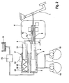
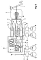
- a first embodiment of a brake system according to the invention is shown schematically.
- the brake system comprises a brake pedal 1 which is coupled to a pedal feel simulator (travel simulator) 2 via a first mechanical connecting means 8 transmitting actuating forces.
- the first mechanical connection 8 is designed as a push rod which connects the brake pedal 1 to the travel simulator 2.
- the pedal feel simulator 2 comprises at least one elastic element, for example a spring 30, and is intended to give the driver a pleasant brake pedal feel.
- the brake system comprises a master cylinder 3, in which at least one pressure piston 4 is displaceably guided, the piston 4 with the master cylinder 3, a pressure chamber 5 for generating a hydraulic brake pressure limited.
- Pressure chamber 5 of the master cylinder 3 is connected by means of brake line 7 with hydraulically actuated wheel brakes 10.
- the brake system comprises an electrically controllable drive device 6 for generating a foreign force for actuating the wheel brakes 10.
- the pressure piston 4 can be actuated via a second mechanical connection means 9 of the electromechanical Fremdkraftaktuator 6. Via the second mechanical connection 9 Actuator 6 can exert a force on the pressure piston 4 for actuating the master cylinder 3.
- Actuator 6 can be controlled in accordance with a brake pedal operation.
- Drive device 6 is arranged between the brake pedal 1 and the master cylinder 3 and between the brake pedal 1 and the travel simulator 2. Accordingly, brake pedal 1 on the one hand and travel simulator 2 and master cylinder 3 on the other hand on opposite sides of the actuator 6 are arranged. The first mechanical connection 8 passes through the actuator 6 accordingly.
- Path simulator 2 comprises, for example, a piston-cylinder arrangement, the simulator piston 31 is guided displaceably in cylinder 33. Simulator piston 31 and cylinder 33 define a space 32 in which spring 30 is arranged, via which simulator piston 31 is supported on cylinder 33. Simulator piston 31 is fixedly connected to the first mechanical connection means 8.
- Displacement simulator 2 and master cylinder 3 are spaced from each other, arranged substantially parallel to the axis side by side.
- pedal feel simulator 2 is arranged coaxially with the first mechanical link 8, which is being formed (e.g., as a push rod) (axial alignment of first mechanical linkage 8 and path simulator 2).
- the second mechanical connecting means 9 comprises a force deflection in order to be able to transmit the force applied by the drive device 6 to the master brake cylinder 3, which is offset radially relative to the displacement simulator 2.
- the second mechanical connection means 9 is designed in a region in and near the actuator 6 as a hollow body, for example as a cylindrical sleeve, and the first mechanical connection means 8 is arranged piecewise within the hollow body.
- the second mechanical connection 9 has, for example in the region of the force deflection, an opening region in the direction of the displacement simulator 2, on which the first mechanical connection 8 emerges from the interior of the hollow body.
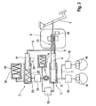
- a second embodiment of a brake system is shown schematically.
- the brake system comprises a brake pedal 1, which is coupled via a first mechanical connection 8 to a travel simulator 2, a master brake cylinder 3 with piston 4 and pressure chamber 5, to which wheel brakes 10 are connected, and an electrically controllable drive device (actuator). 6, which is coupled or coupled via a second mechanical connection 9 with the pressure piston 4.
- Brake pedal 1 on the one hand and travel simulator 2 and master cylinder 3 on the other hand are arranged on opposite sides of the actuator 6, wherein the displacement simulator 2 and master cylinder 3 are arranged side by side.
- the first mechanical connection 8 extends through the actuator 6.
- the second mechanical connection means 9 is designed substantially as a cylindrical hollow body and master cylinder 3 is arranged coaxially with the second mechanical connection means 9 (axial alignment of the second mechanical connection means 9 and master cylinder 3).
- the first mechanical connection 8 comprises a force deflection in order to be able to transmit the brake pedal actuation to the travel simulator 2, which is arranged offset radially to the master brake cylinder 3.
- the first mechanical connection 8 extends at least partially within the hollow body of the second connecting means 9.
- Connecting means 9 has an opening area perpendicular to the direction of the master cylinder axis / second mechanical connection, in which the first mechanical connection 8 emerges from the interior of the hollow body.
- the first 8 and the second 9 mechanical connection are formed such that upon a displacement of the first mechanical connection 8 relative to the second mechanical connection 9 (in the direction of a brake operation), which reaches a predetermined amount (distance d is overcome), the first mechanical connection 8 mechanically engages the second mechanical connection 9 or the piston 4, so that the force acting on the first mechanical connection 8 from a brake pedal operation is transmitted to the master cylinder 3.
- the first mechanical connecting means 8 is arranged on the first mechanical connecting means 8 a molding 11 which can engage with a arranged on the second mechanical connection means 9 stop 12, so that the actuating force from the first mechanical connection 8 on the second mechanical connection 9 and thus on the master cylinder 3 is transmitted.
- the first mechanical connection 8 in the field of force deflection (when reaching the end of the opening in the second mechanical connection 9) come into contact with the pressure piston 4, ie piston 4 forms a stop 12 for the connection 8. Accordingly, the actuating force in the mechanical fallback mode of the first mechanical connection 8 can be transmitted directly to the master cylinder 3.
- the second mechanical connection 9 in the region of the actuator 6 is fixedly connected thereto, i. in the case of blocking of the actuator 6, the second mechanical connection 9 is prevented by actuator 6 from moving.
- the force acting on the brake pedal 1 in the fallback plane via the first mechanical connection 8 can be transmitted to the master cylinder 3, the second mechanical connection 9 according to the first embodiment ( Fig. 1 ) formed in two parts.
- the first part of the second mechanical connection 9, which is fixedly connected to the actuator 6, is prevented by the actuator 6 from moving, whereas the second part of the second mechanical connection 9, which is fixedly connected to the piston 4, via the molding 11th the first mechanical connection 8 can be moved in the direction of the master cylinder 3.
- the second mechanical connection 9 is divided into two parts in the region of the stop 12.
- the stop 12 is arranged on the second part of the second mechanical connection 9.
- the second mechanical connection 9 is integrally formed and firmly connected to the actuator 6, but not firmly connected to the piston 4. Accordingly, piston 4 can be actuated by the first mechanical connection 8 in the brake actuation direction, with piston 4 moving away from connection 9.
- the pressure chamber 5 of the master cylinder 3 via an electrically controllable, eg normally closed, exhaust valve 15 with a pressure fluid reservoir 14 is connectable.
- Pressure medium tank 14 has a low pressure level and is designed, for example, as a low-pressure accumulator or a pressure medium reservoir (atmospheric pressure). The operation of the exhaust valve 15 will be explained below.
- Actuator 6 is driven accordingly, so that pressure piston 4 can retreat (against the brake actuation direction) and the brake pressure in the wheel brakes 10 is reduced in accordance with the brake pedal operation. At a similar shift Thus, there is no contact with stop 12 of the first 8 and second 9 mechanical connecting means.
- the master cylinder 3 can be actuated via the second mechanical connection 9 of the actuator 6.
- the first 8 and the second 9 are mechanical connection, e.g. in terms of lengths and relative arrangement of force deflection, opening area, etc., designed such that a displacement of the second mechanical connection 9 (in the brake actuation direction) relative to the first mechanical connection 8 over a predetermined length 13 is possible without it to a force-transmitting connection ( a stop) and thus comes to a reaction to the brake pedal 1.
- the second mechanical connection 9 can be moved over the length 13 in the brake actuation direction before the second mechanical connection 9 comes into contact with the simulator piston 31 of the travel simulator 2 in the opening region and causes a further movement of the simulator piston 31, which causes a reaction to the brake pedal 1 leads.
- the second mechanical connection 9 can be moved in the brake actuation direction over the length 13 before the second mechanical connection 9 comes into contact with the first mechanical connection 8 with the end of the opening region facing the brake pedal 1.
- a driving of the first mechanical connection 8 is effected in the brake actuation direction, which leads to an entrainment of the brake pedal 1.
- the second mechanical connection 9 is moved by the actuator 6 against the brake actuation direction. If the brake pedal operation by the driver and thus the position of the first mechanical connection 8 remains unchanged, it may come to a contact on the stop 12, ie there would be a force on the first mechanical connection 8. Such a reaction would be for the driver on the brake pedal 1 felt and would be distracting.
- an approach of the stop 12 to the first mechanical connection 8, 11 is advantageously based on a sensor device 34, which the position / position of a component of the path simulator 2 (eg the piston 31) or the position / position of the first mechanical connection 8, and a sensor device 35, which detects the position / position of a component of the actuator 6, and thus the second mechanical connection 9, or the piston 4 of the master cylinder 3, detected and monitored. If the distance between the stop 12 and the first mechanical connection 8, 11 drops below a threshold, then the normally closed valve 15 is opened and thus pressure chamber 5 of the master cylinder 3 is connected to pressure medium container 14, whereby a reduction of the system pressure, and thus possibly in the wheel brakes 10th , is achieved. Further return of the second mechanical connection 9 against the brake actuation direction by the actuator 6 is then no longer necessary.
- a sensor device 34 which the position / position of a component of the path simulator 2 (eg the piston 31) or the position / position of the first mechanical connection 8, and a sensor device 35, which detects the position /
- the brake system according to the invention is advantageously used in motor vehicles, which can be braked by means of generator operation of an electric drive motor (also called regenerative braking or recuperation braking).
- an electric drive motor also called regenerative braking or recuperation braking.
- the friction brakes 10 should not be operated or possibly only supportive in general to achieve the highest possible energy yield of the recuperation. Accordingly, during recuperation braking, brake pedal operation by the driver (i.e., displacement of the first mechanical link 8, 11 in the brake actuation direction) should not result in (significant) brake pressure build-up in the wheel brakes 10.
- the normally closed valve 15 can therefore be opened in the brake systems according to the invention and the pressure chamber 5 of the master cylinder 3 are connected to pressure fluid reservoir 14 so that in the case of actuation of the master cylinder 3 by the first mechanical connection means (via stop 12) pressure medium in the pressure fluid reservoir 14 can drain.
- actuator 6 can be actuated in order to actuate master brake cylinder 3 via second mechanical connection means 9.
- a critical approach of the first mechanical connection 8, 11 to the stop 12 can, as already explained above, be recognized on the basis of the sensor devices 34, 35.
- Displacement simulator 2 is advantageously designed switchable.
- path simulator 2 and its shutdown is designed such that in case of failure of the brake system, for example in a power failure, no or low power loss remains effective.
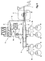
- a third embodiment of a brake system according to the invention is shown schematically.
- the second mechanical connection means 9 is designed substantially as a cylindrical hollow body and master cylinder 3 is arranged coaxially with the second mechanical connection means 9.
- the first mechanical connection 8 comprises a force deflection in order to be able to transmit the brake pedal actuation to the displacement simulator 2 arranged radially offset from the master brake cylinder 3, and extends at least partially within the hollow body of the second connection means 9 and extends through the actuator 6.
- the displacement simulator 2 according to the third embodiment is designed hydraulically.
- Displacement simulator 2 comprises a piston-cylinder arrangement whose simulator piston 31 is displaceably guided in cylinder 33 and which comprises a hydraulic space 32 '. Simulator piston 31 is actuated by the first mechanical connection means 8 and fixedly connected thereto.
- path simulator 2 comprises a further simulator arrangement 36, which is hydraulically connected to the hydraulic space 32 'of the piston-cylinder arrangement 31, 33.
- the hydraulic chamber 32 'of the travel simulator 2 is connected via an electrically controllable, eg normally open, valve 16 with a pressure medium container 14 to allow a shutdown of the simulator 2 (eg in the fallback mode).
- the pressure medium container 14 is executed, for example, as a low-pressure accumulator, but may also be designed as a pressure medium reservoir.
- the hydraulic space 32 'of the travel simulator 2 and the pressure chamber 5 of the master cylinder 3 with the same pressure fluid reservoir 14 are connected, as Fig. 3 refer to is. However, it can also be two pressure fluid containers.
- valve 16 In normal operation of the brake system (operating mode "brake-by-wire") valve 16 is closed (energized according to the example) and the hydraulic chamber 32 'of the simulator 2 is separated from the pressure fluid reservoir 14.
- the brake master cylinder 3 of the brake system is designed such that with a pedal actuation force of 500N, a vehicle deceleration of at least 0.5 g (g: acceleration due to gravity) can be achieved.
- the brake system advantageously comprises a filling device, with which a pre-filling of the wheel brakes 10 can be performed.
- the filling device comprises, for example, a cylinder-piston arrangement with a hydraulic chamber whose piston can be actuated by the first mechanical connection 8.
- the hydraulic space of the filling device is connected to the wheel brakes 10 or the pressure chamber 5 of the master cylinder 3.
- the wheel brakes 10 can be filled up to a predetermined pressure.
- the predetermined pressure is adjustable / specifiable eg by a pressure relief valve or by the bias of a low-pressure accumulator spring.
- the piston of the filling device Upon actuation of the brake pedal 1, the piston of the filling device is actuated by the first mechanical connection 8 and so the wheel brakes 10 filled from the filling until a predetermined by the pressure relief valve or the bias of the spring of the low pressure accumulator pressure value is reached.
- the displacement simulator 2 or its cylinder-piston arrangement 31, 32 ', 33 is used as a filling device.
- the hydraulic chamber 32 'of the travel simulator 2 via a check valve 17 to the master cylinder 3 and thus the wheel brakes 10 is connected.
- the bias of the spring of the low-pressure accumulator 14 limits the filling pressure.
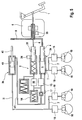
- Fig. 4 is a fourth embodiment of a brake system according to the invention shown schematically, in which the master cylinder is designed as a tandem master cylinder 3 (in axial construction).
- the primary piston 4 of the tandem master cylinder 3 is actuated via the second mechanical connection means 9 of the electromechanical Fremdkraftaktuator 6.
- the primary piston circuit I and the floating piston circuit II are each connected to two wheel brakes 10.
- an electrically controllable, eg normally open, valve 18 per wheel brake 10 is arranged in the brake lines 7 to the wheel brakes 10.
- a brake pressure modulation can be carried out by means of the (reversing) actuator 6 in a multiplex process.
- the other components of the brake system and their arrangement essentially correspond to those of the third embodiment.
- Fig. 5 is a fifth embodiment of a brake system according to the invention with a tandem master cylinder 3a, 3b in a dissolved design shown schematically.
- Displacement simulator 2 is arranged coaxially with the first mechanical connection means 8.
- the tandem master cylinder 3 comprises two cylinder-piston assemblies, wherein the cylinder-piston assembly 3a of the primary piston circuit is formed parallel to the cylinder-piston assembly 3b of the floating piston circuit.
- the pressure piston 4 of the cylinder-piston assembly 3a is (about the mechanical connecting means 9) is mechanically coupled to the drive device 6 and the piston 40 of the cylinder-piston assembly 3b is hydraulically coupled via a line 41 to the piston 4.
- Both cylinder-piston assemblies 3a, 3b are arranged parallel to the travel simulator 2, wherein the cylinder-piston assemblies 3a, 3b are arranged on opposite sides of the travel simulator 2.
- the second mechanical connection 9 is advantageously designed such that the piston 40 of the floating piston circle can also be actuated mechanically by means of the second mechanical connection means 9 (eg in the event of a failure of the primary piston circuit).
- the piston 40 of the floating piston circuit is actuated only from a predetermined displacement of the second mechanical connection 9 in the brake actuation direction.
- Fig. 6 shows a sixth embodiment of a brake system according to the invention.
- the master cylinder 3 is designed as a tandem master cylinder in dissolved construction.
- the primary piston circuit and the floating piston circle are each formed by two cylinder-piston assemblies 3a and 3b, wherein the piston surface of a piston each half is large as piston area of the corresponding pressure piston per circle of the fifth embodiment.
- the pressure chambers of the two cylinder-piston assemblies of a circle are connected to each other via a hydraulic line (eg line 43 for cylinder-piston assemblies 3a).
- the two cylinder-piston assemblies 3a and 3b of a circle I and II are respectively arranged parallel to the displacement simulator 2, on opposite sides of the displacement simulator 2 and symmetrical to the axis of the first mechanical connection means 8.
- This division into two cylinder-piston assemblies (each circle) and their symmetrical arrangement allows torque-free force introduction by the actuator 6.
- the two piston assemblies 3b of the floating piston circuit are rotated by 90 degrees against each other the two piston assemblies 3a of the primary piston circuit , Therefore, in Fig. 6 only the primary piston circuit (piston assemblies 3a) shown, the piston assemblies 3b are arranged rotated by 90 degrees and not shown for the sake of clarity.
- Fig. 6 only the primary piston circuit (piston assemblies 3a) shown, the piston assemblies 3b are arranged rotated by 90 degrees and not shown for the sake of clarity.
- Fig. 6 only the primary piston circuit (piston assemblies 3a) shown, the piston assemblies 3b are arranged rotated by 90 degrees and not shown for the sake of clarity.
- Displacement simulator 2 comprises two piston-cylinder assemblies 2a, 2b, whose simulator pistons 31a, 31b are actuated jointly by the first mechanical connection means 8, which comprises two force deflections.
- the two piston-cylinder assemblies 2 a, 2 b are arranged symmetrically on opposite sides of the master cylinder 3. As a result, a torque-free operation of the brake pedal 1 via the first mechanical connection 8 is possible.
- the brake system according to the seventh embodiment includes one wheel brake 10, for example, without power open, valve 18, which uses the actuator 6 for brake pressure modulation in the multiplex process.
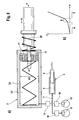
- Fig. 8a shows schematically a section of an eighth embodiment of a brake system according to the invention.
- Pressure chamber 5 of the master cylinder 3 is connected by means of brake line 7 with hydraulically actuated wheel brakes 10.
- Pedal feel simulator 2 is designed hydraulically and comprises a cylinder-piston arrangement with a hydraulic chamber 32 ', which is connectable to the wheel brakes 10.
- a hydraulic chamber 32 ' which is connectable to the wheel brakes 10.
- an electrically controllable for example, normally open, separating valve 19 is arranged.
- the pedal feel simulator 2 is additionally designed, for example, in such a way that the pressure feedback (eg from the wheel brakes 10) is reduced in a lower pressure range.
- the pedal feel simulator 2 comprises two different active surfaces A1, A2 and optionally a spring 20.
- the hydraulic chamber 32 ' is bounded by a first piston 21 with active surface A1 and a second piston 31 with a smaller effective area A2 which extends through the first piston 21, piston 31 is actuated by the first mechanical connecting means 8 and is supported in the brake actuating direction via spring 20 on the piston 21.
- the active surfaces A1, A2 of the travel simulator 2 are acted upon by the pressure of the wheel brakes 10 and by the structure of the simulator 2 (two offset effective piston surfaces A1, A2 different size, slow transition by spring 20), the pressure feedback is reduced in a lower pressure range ( so-called Springer function).
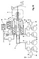
- a ninth embodiment of a brake system according to the invention is shown schematically.
- the displacement simulator 2 is designed in two stages, wherein the first stage is carried out according to the eighth embodiment.
- Displacement simulator 2 comprises a piston-cylinder arrangement with two successively arranged hydraulic chambers 32 'and 26, which are separated by a floating piston.
- piston 31 By means of the first mechanical connection means 8 piston 31 is actuated.
- Each of the hydraulic chambers 32 ', 26 of the travel simulator 2 is connected to a brake circuit I, II, each with two wheel brakes 10, wherein each wheel brake is connected upstream of a normally open valve 18 for braking pressure modulation.
- Per brake circuit I, II is a normally open release valve 19 for preventing pressure interactions in a brake pressure modulation between the hydraulic chamber 32 ', 26 and wheel brakes 10 is arranged.
- Master cylinder 3 is designed as a tandem master cylinder in dissolved construction, the primary piston and the floating piston circuit are each formed by two cylinder-piston assemblies 3a and 3b, which arranged for torque-free force introduction by the actuator 6 symmetrical to the axis of the first mechanical connection 8 are (on opposite longitudinal sides of the path simulator 2).
- the two cylinder-piston assemblies 3b of the floating piston circuit are arranged rotated by 90 degrees relative to the two cylinder-piston assemblies 3a of the primary piston circuit, which is why only the primary piston circuit in Fig. 9 is shown.
- the displacement simulator 2 is used as a filling device (principle of the volume amplifier).
- the hydraulic space 32 'of the travel simulator 2 with the brake circuit I and thus the corresponding wheel brakes 10 is connected.
- the hydraulic space 32 ' is electrically controllable, e.g. normally closed, valve 15 connected to a low pressure accumulator 14. The bias of the spring of the low-pressure accumulator 14 limits the filling pressure.
- the sensor device 34 which detects the state of the travel simulator 2 is designed as a travel sensor 34 for sensing the position / displacement of the piston 31 of the travel simulator 2 or a component connected thereto.
- the brake system comprises, for example, a Pressure sensor 22 for measuring the pressure of the primary piston circuit.
- Fig. 9 can be removed, the hydraulic components of the brake system, in particular travel simulator 2, master cylinder 3 and the valves 15, 18, 19, and optionally also the sensor devices, such as sensor devices 34, 22, advantageously arranged in a housing 23.
- Housing 23 can be easily arranged on the brake pedal 1 side facing away from the drive device 6. Only the two mechanical connecting means 8 and 9 thus extend from the housing of the drive device 6 to the housing 23.
- route simulator 2 is advantageously connected to the wheel brakes 10 via one or more normally open isolation valves 19 (see FIG Fig. 8 and 9 ).
- the multiplex valves 18 are closed to prevent pressure build-up in the wheel brakes 10.
- the volume displaced by the driver in the travel simulator 2 is discharged via valve 15 into a low-pressure accumulator 14.
- the back pressure in the travel simulator 2 is simulated by suitable activation of the actuator 6.
- a tenth embodiment of a brake system according to the invention is shown schematically. This embodiment largely corresponds to the seventh embodiment.
- the brake system additionally comprises one or more, eg all, wheel brake circuits electrically controllable, eg normally closed, valves 24, by means of which a connection to a low Pressure level 25
- pressure medium reservoir (atmospheric pressure) or low pressure accumulator) can be produced.
- two of the wheel brakes 10 are additionally connectable via valves 24 with a low pressure level 25, whereby a rapid brake pressure reduction in these wheel brakes is possible. This provides a possibility to improve the speed of the brake pressure modulation in the case of a simultaneous need for a pressure reduction at a wheel brake and a pressure build-up on another wheel brake.
- the electrically controllable electromechanical drive device 6 of the embodiments includes e.g. an electric motor and a rotation-translation gear, e.g. a ball screw, to implement a rotary motion of the electric motor in a linear motion.
- the drive device 6 is arranged in a housing, wherein the first mechanical connecting means 8 humiliatrecht the housing therethrough.
- a brake system comprises a sensor device 34 for detecting the state of the travel simulator 2, eg for detecting the position of a component of the travel simulator (eg a piston 31) or for detecting the position / position of the first mechanical connection means 8, as well as a sensor device 35 for detecting the state of the master cylinder 3, for example for detecting the position / position of a piston 4 of the master cylinder 3 or the position / position of the second mechanical connection means 9 or the position / position of a component of the actuator 6 (eg the rotor position of the electric motor or the position a spindle of a rotation-translation gear).
- a sensor device 34 for detecting the state of the travel simulator 2, eg for detecting the position of a component of the travel simulator (eg a piston 31) or for detecting the position / position of the first mechanical connection means 8, as well as a sensor device 35 for detecting the state of the master cylinder 3, for example for detecting the position / position of a piston 4 of the master cylinder 3 or
- a brake system advantageously comprises a sensor device 22 for detecting a pressure in the master cylinder 3 and / or in a wheel brake 10 and / or a sensor device for detecting a pressure in the travel simulator 2.
Landscapes
- Engineering & Computer Science (AREA)
- Transportation (AREA)
- Mechanical Engineering (AREA)
- Physics & Mathematics (AREA)
- Fluid Mechanics (AREA)
- Regulating Braking Force (AREA)
Claims (15)
- Système de freinage pour véhicules automobiles, ledit système pouvant être commandé, dans un mode de fonctionnement de type à commande électronique, tant par le conducteur du véhicule qu'indépendamment du conducteur du véhicule, ledit système étant de préférence entraîné dans un mode de fonctionnement de type à commande électronique et pouvant être entraîné dans un mode de fonctionnement de relâchement dans lequel seul l'actionnement par le conducteur du véhicule est possible ; avec :- une pédale de frein (1) ;- un simulateur de course (2) couplé à la pédale de frein (1) via un premier moyen de liaison mécanique (8) transmettant les forces d'actionnement et donnant au conducteur du véhicule une sensation de pédale de frein agréable dans le mode de fonctionnement à commande électronique ;- un maître-cylindre de frein (3) comportant au moins une chambre de pression (5) et un piston (4), la chambre de pression (5) dudit maître-cylindre de frein étant reliée ou pouvant être reliée à au moins un frein de roue (10) pouvant être actionné hydrauliquement via une conduite de pression (7) ; et- un dispositif d'entraînement électromécanique (6) à commande électrique à l'aide duquel le piston (4) du maître-cylindre de frein (3) peut être actionné via un deuxième moyen de liaison mécanique (9) et à l'aide duquel le maître-cylindre de frein (3) est actionné dans le mode de fonctionnement à commande électronique ;caractérisé en ce que le dispositif d'entraînement électromécanique (6) est disposé entre :- la pédale de frein (1) d'une part ; et- le maître-cylindre de frein (3) et le simulateur de course (2) d'autre part, le premier moyen de liaison mécanique (8) s'étendant de la pédale de frein (1) jusqu'au simulateur de course (2) en passant au travers du dispositif d'entraînement (6).
- Système de freinage selon la revendication 1, caractérisé en ce qu'un des moyens de liaison mécanique (9), notamment le deuxième moyen de liaison mécanique est réalisé au moins en partie sous la forme d'un corps creux et que l'autre moyen de liaison mécanique (8), notamment le premier moyen de liaison mécanique, est disposé au moins en partie à l'intérieur du corps creux.
- Système de freinage selon la revendication 1 ou 2, caractérisé en ce que le simulateur de course (2) comprend au moins un agencement piston-cylindre dont le piston de simulateur (31) est relié au premier moyen de liaison mécanique (8).
- Système de freinage selon la revendication 3, caractérisé en ce que le piston de simulateur (31) délimite une chambre hydraulique (32').
- Système de freinage selon la revendication 4, caractérisé en ce que la chambre hydraulique (32') est reliée ou peut être reliée à au moins un frein de roue (10).
- Système de freinage selon la revendication 4 ou 5, caractérisé en ce que la chambre hydraulique (32') est reliée à un accumulateur de basse pression (14) via une soupape (16) à commande électrique.
- Système de freinage selon l'une quelconque des revendications 4 à 6, caractérisé en ce que le simulateur de course (2) comprend en sus du piston de simulateur (31) un piston (21) supplémentaire et un ressort (20), le piston de simulateur (31) possédant une surface active de piston (A1) plus petite que celle du piston (A2) supplémentaire, le piston de simulateur étant guidé de façon mobile dans le piston (21) supplémentaire et s'appuyant contre le piston (21) supplémentaire à l'aide du ressort (20).
- Système de freinage selon l'une quelconque des revendications 4 à 7, caractérisé en ce qu'une soupape de séparation (19) ouverte sans courant et à commande électrique est disposée entre la chambre hydraulique (32') du simulateur de course (2) et le frein de roue (10).
- Système de freinage selon l'une quelconque des revendications 4 à 6, caractérisé en ce que la chambre hydraulique (32') est reliée au maître-cylindre de frein (3) via une soupape de retenue (17), elle-même reliée à au moins un frein de roue (10).
- Système de freinage selon l'une quelconque des revendications 3 à 9, caractérisé en ce que l'agencement piston-cylindre du simulateur de course (2) et du maître-cylindre de frein (3) sont disposés côte à côte pour l'essentiel parallèlement à l'axe et en ce qu'au moins le premier ou le deuxième moyen de liaison mécanique (8, 9) comprend un moyen de déviation de force.
- Système de freinage selon l'une quelconque des revendications 1 à 10, caractérisé en ce que le premier (8) et le deuxième (9) moyen de liaison mécanique sont réalisés de telle sorte (11, 12) qu'ils permettent l'actionnement du maître-cylindre de frein (3) dans la direction d'actionnement de frein à l'aide du premier moyen de liaison mécanique (8), par le biais d'un contact (12) mécanique entre le premier moyen de liaison mécanique (8) et le maître-cylindre de frein (3) ou le premier moyen de liaison mécanique (8, 11) et le deuxième moyen de liaison mécanique (9).
- Système de freinage selon l'une quelconque des revendications 1 à 11, caractérisé en ce que celui-ci comprend au moins un dispositif de détection (34, 35) à l'aide duquel la position relative du premier (8) par rapport au deuxième (9) moyen de liaison mécanique est définie.
- Système de freinage selon l'une quelconque des revendications 1 à 12, caractérisé en ce que la chambre de pression (5) du maître-cylindre de frein (3) peut être reliée à un bac de moyen de pression (14) via une soupape (15) à commande électrique.
- Système de freinage selon l'une quelconque des revendications 1 à 13, caractérisé en ce que le deuxième moyen de liaison mécanique (9) est réalisé de telle sorte, notamment en deux parties, ou que le couplage entre le piston (4) du maître-cylindre de frein (3) et le deuxième moyen de liaison mécanique (9) est réalisé de telle sorte, notamment de façon amovible, que le piston (4) du maître-cylindre de frein (3) peut être actionné à l'aide du premier moyen de liaison mécanique (8), également lorsque le dispositif d'entraînement (6) est bloqué.
- Système de freinage selon l'une quelconque des revendications 1 à 14, caractérisé en ce que le premier moyen de liaison mécanique (8) et le deuxième moyen de liaison mécanique (9) sont réalisés de telle sorte que le deuxième moyen de liaison mécanique (9) peut être déplacé par le dispositif d'entraînement (6) sur une course (13) prédéfinie dans la direction d'actionnement de frein, par rapport au premier moyen de liaison mécanique (8), sans qu'un engrenage ou une rétroaction se produisent sur la pédale de frein (1).
Applications Claiming Priority (3)
| Application Number | Priority Date | Filing Date | Title |
|---|---|---|---|
| DE102010028399 | 2010-04-30 | ||
| DE102011007353A DE102011007353A1 (de) | 2010-04-30 | 2011-04-14 | Bremsanlage für Kraftfahrzeuge |
| PCT/EP2011/056209 WO2011134841A1 (fr) | 2010-04-30 | 2011-04-19 | Système de freinage pour véhicules automobiles |
Publications (2)
| Publication Number | Publication Date |
|---|---|
| EP2563630A1 EP2563630A1 (fr) | 2013-03-06 |
| EP2563630B1 true EP2563630B1 (fr) | 2016-06-29 |
Family
ID=44227906
Family Applications (1)
| Application Number | Title | Priority Date | Filing Date |
|---|---|---|---|
| EP11715529.1A Not-in-force EP2563630B1 (fr) | 2010-04-30 | 2011-04-19 | Système de freinage pour véhicules automobiles |
Country Status (5)
| Country | Link |
|---|---|
| US (1) | US9174617B2 (fr) |
| EP (1) | EP2563630B1 (fr) |
| CN (1) | CN102869552B (fr) |
| DE (1) | DE102011007353A1 (fr) |
| WO (1) | WO2011134841A1 (fr) |
Families Citing this family (15)
| Publication number | Priority date | Publication date | Assignee | Title |
|---|---|---|---|---|
| FR2979089B1 (fr) * | 2011-08-19 | 2014-02-14 | Bosch Gmbh Robert | Systeme de freins dynamique electro-hydraulique et procede de commande |
| DE102012025247B4 (de) * | 2012-12-21 | 2025-04-17 | Zf Active Safety Gmbh | Elektrohydraulische Fahrzeug-Bremsanlage und Verfahren zum Betreiben derselben |
| US9340191B2 (en) * | 2013-03-13 | 2016-05-17 | Autoliv Asp, Inc. | Braking system for a vehicle |
| CN110576840B (zh) * | 2013-09-16 | 2022-02-01 | 爱皮加特股份公司 | 制动设备和用于制动设备的运行的方法 |
| KR102115716B1 (ko) * | 2013-10-07 | 2020-05-27 | 현대모비스 주식회사 | 전자식 유압 브레이크장치 |
| CN103909916A (zh) * | 2014-01-08 | 2014-07-09 | 同济大学 | 一种电子液压制动系统的轮缸液压力控制系统及方法 |
| DE102014011598B3 (de) * | 2014-08-01 | 2015-11-19 | Audi Ag | Blendingfähiges Bremssystem |
| CN104309599A (zh) * | 2014-09-26 | 2015-01-28 | 同济大学 | 一种电子液压制动系统 |
| CN108263362B (zh) * | 2016-12-30 | 2022-04-01 | 罗伯特·博世有限公司 | 车辆及其液压制动联合系统 |
| KR102356584B1 (ko) | 2017-05-17 | 2022-01-28 | 주식회사 만도 | 전자식 브레이크 시스템 |
| US10800389B2 (en) | 2018-08-31 | 2020-10-13 | Robert Bosch Gmbh | Haptic feedback for decoupled brake system |
| DE102018221077A1 (de) * | 2018-12-06 | 2020-06-10 | Robert Bosch Gmbh | Verfahren zur Steuerung eines elektronisch schlupfregelbaren Bremssystems für ein Kraftfahrzeug |
| KR102671510B1 (ko) * | 2019-05-02 | 2024-06-03 | 에이치엘만도 주식회사 | 액압 공급장치 |
| DE102021119443A1 (de) * | 2021-07-27 | 2023-02-02 | Zf Active Safety Gmbh | Bremspedalmodul |
| CN116620228B (zh) * | 2023-06-25 | 2026-01-09 | 浙江极氪智能科技有限公司 | 制动踏板系统及车辆 |
Family Cites Families (18)
| Publication number | Priority date | Publication date | Assignee | Title |
|---|---|---|---|---|
| DE3131095A1 (de) * | 1981-08-06 | 1983-02-24 | Alfred Teves Gmbh, 6000 Frankfurt | Hilfskraftunterstuetzte hauptzylinderanordnung fuer eine fahrzeugbremsanlage |
| DE3409290A1 (de) * | 1984-03-14 | 1985-09-19 | Robert Bosch Gmbh, 7000 Stuttgart | Hydraulischer bremsverstaerker |
| DE3445566C2 (de) * | 1984-12-14 | 1997-05-22 | Teves Gmbh Alfred | Bremskraftverstärker für eine hydraulische Fahrzeugbremsanlage |
| DE4430168B4 (de) * | 1994-08-25 | 2004-12-02 | Robert Bosch Gmbh | Fahrzeugbremsanlage |
| DE19640767A1 (de) * | 1996-10-02 | 1998-04-09 | Teves Gmbh Alfred | Einrichtung zur Betätigung einer Kraftfahrzeug-Bremsanlage |
| JP2002321611A (ja) * | 2001-04-26 | 2002-11-05 | Bosch Braking Systems Co Ltd | 電動式ブレーキ倍力装置 |
| WO2004005095A1 (fr) * | 2002-07-09 | 2004-01-15 | Continental Teves Ag & Co. Ohg | Dispositif d'actionnement de frein par cable |
| US20060186735A1 (en) * | 2003-07-08 | 2006-08-24 | Continental Teves Ag & Co., Ohg | Method for monitoring a hydro-electrical brake system |
| EP1538049B1 (fr) * | 2003-12-05 | 2006-11-29 | Nissin Kogyo Co., Ltd. | Système de freinage d'un véhicule |
| DE102005036638A1 (de) * | 2004-10-15 | 2006-04-27 | Continental Teves Ag & Co. Ohg | Bremsanlage für Kraftfahrzeuge |
| DE102005017958A1 (de) * | 2004-10-15 | 2006-04-27 | Continental Teves Ag & Co. Ohg | Bremsanlage für Kraftfahrzeuge |
| DE102005018649B4 (de) * | 2005-04-21 | 2018-10-31 | Ipgate Ag | Bremssystem mit elektromotorisch angetriebenem Kolben-Zylinder-System |
| US7367187B2 (en) | 2005-06-30 | 2008-05-06 | Hitachi, Ltd. | Electrically actuated brake booster |
| WO2007034961A1 (fr) * | 2005-09-26 | 2007-03-29 | Hitachi, Ltd. | Dispositif d’assistance électrique motorisé |
| WO2007138012A1 (fr) * | 2006-06-01 | 2007-12-06 | Continental Teves Ag & Co. Ohg | Unité d'actionnement de frein |
| DE102007016864B4 (de) | 2007-04-10 | 2024-11-14 | Robert Bosch Gmbh | Bremssystem für ein Fahrzeug |
| JP4449067B2 (ja) * | 2007-04-11 | 2010-04-14 | 功 松野 | 車両用ブレーキ装置 |
| KR101107510B1 (ko) * | 2008-01-10 | 2012-02-06 | 주식회사 만도 | 전자유압브레이크시스템의 제동장치 |
-
2011
- 2011-04-14 DE DE102011007353A patent/DE102011007353A1/de not_active Withdrawn
- 2011-04-19 WO PCT/EP2011/056209 patent/WO2011134841A1/fr not_active Ceased
- 2011-04-19 CN CN201180021867.XA patent/CN102869552B/zh not_active Expired - Fee Related
- 2011-04-19 EP EP11715529.1A patent/EP2563630B1/fr not_active Not-in-force
- 2011-04-19 US US13/695,179 patent/US9174617B2/en not_active Expired - Fee Related
Non-Patent Citations (1)
| Title |
|---|
| None * |
Also Published As
| Publication number | Publication date |
|---|---|
| US9174617B2 (en) | 2015-11-03 |
| WO2011134841A1 (fr) | 2011-11-03 |
| CN102869552B (zh) | 2015-04-08 |
| DE102011007353A1 (de) | 2011-12-22 |
| US20130043718A1 (en) | 2013-02-21 |
| CN102869552A (zh) | 2013-01-09 |
| EP2563630A1 (fr) | 2013-03-06 |
Similar Documents
| Publication | Publication Date | Title |
|---|---|---|
| EP2563630B1 (fr) | Système de freinage pour véhicules automobiles | |
| DE112011106127B3 (de) | Betätigungsvorrichtung für eine Kraftfahrzeug-Bremsanlage | |
| DE102011101066B4 (de) | Hydraulische Fahrzeug-Bremsanlage mit elektromechanischem Aktuator | |
| EP3074285B1 (fr) | Système de freinage électrohydraulique d'un véhicule automobile | |
| EP3116758B1 (fr) | Procédé d'étalonnage d'un système de freinage électrohydraulique de véhicule automobile et dispositif d'étalonnage | |
| EP2744692B1 (fr) | Mechanisme de freinage electromechanique | |
| EP2934961B1 (fr) | Système de freinage électrohydraulique pour véhicule et procédé de fonctionnement | |
| WO2013030113A1 (fr) | Systèmes d'actionnement pour systèmes de freinage de véhicule à moteur et procédé de fonctionnement d'un système d'actionnement pour un frein de véhicule | |
| EP2934973B1 (fr) | Système de freinage électrohydraulique pour véhicule et procédé de fonctionnement | |
| DE102010045617A1 (de) | Betätigungsvorrichtung für eine Kraftfahrzeug-Bremsanlage | |
| DE102009033499A1 (de) | Bremsanlage für Kraftfahrzeuge | |
| WO2012059175A1 (fr) | Dispositif d'actionnement, en particulier pour un système de freinage de véhicule | |
| DE102015006853A1 (de) | Elektrohydraulische Kraftfahrzeug-Bremsanlage | |
| DE102011085986A1 (de) | Bremsanlage | |
| EP2635471B1 (fr) | Servofrein et son procédé de fonctionnement | |
| DE102011084391A1 (de) | Bremsanlage für Kraftfahrzeuge und Verfahren zu deren Betrieb | |
| WO2016184609A1 (fr) | Dispositif de production de force de freinage électrohydraulique pour un système de freinage électrohydraulique de véhicule à moteur | |
| EP2635470A1 (fr) | Servofrein et son procédé de production | |
| DE102006059840A1 (de) | Adaptive Leerwegreduzierung | |
| DE102015103859A1 (de) | Hydraulische Einrichtung, insbesondere Bremseinrichtung für Kraftfahrzeuge | |
| DE102011116167A1 (de) | Elektrohydraulische Betätigungsbaugruppe für eine Fahrzeug-Bremsanlage | |
| EP2414202B1 (fr) | Actionneur de frein pour systeme de freinage de vehichule de type "brake-by-wire" | |
| DE102012002117A1 (de) | Bremsvorrichtung für Kraftfahrzeuge | |
| DE102015217708A1 (de) | Bremsanlage für Kraftfahrzeuge | |
| DE102014202373A1 (de) | Hydraulische Kraftfahrzeugbremsanlage |
Legal Events
| Date | Code | Title | Description |
|---|---|---|---|
| PUAI | Public reference made under article 153(3) epc to a published international application that has entered the european phase |
Free format text: ORIGINAL CODE: 0009012 |
|
| 17P | Request for examination filed |
Effective date: 20121130 |
|
| AK | Designated contracting states |
Kind code of ref document: A1 Designated state(s): AL AT BE BG CH CY CZ DE DK EE ES FI FR GB GR HR HU IE IS IT LI LT LU LV MC MK MT NL NO PL PT RO RS SE SI SK SM TR |
|
| DAX | Request for extension of the european patent (deleted) | ||
| 17Q | First examination report despatched |
Effective date: 20150415 |
|
| GRAP | Despatch of communication of intention to grant a patent |
Free format text: ORIGINAL CODE: EPIDOSNIGR1 |
|
| INTG | Intention to grant announced |
Effective date: 20160318 |
|
| GRAS | Grant fee paid |
Free format text: ORIGINAL CODE: EPIDOSNIGR3 |
|
| GRAA | (expected) grant |
Free format text: ORIGINAL CODE: 0009210 |
|
| AK | Designated contracting states |
Kind code of ref document: B1 Designated state(s): AL AT BE BG CH CY CZ DE DK EE ES FI FR GB GR HR HU IE IS IT LI LT LU LV MC MK MT NL NO PL PT RO RS SE SI SK SM TR |
|
| REG | Reference to a national code |
Ref country code: GB Ref legal event code: FG4D Free format text: NOT ENGLISH |
|
| REG | Reference to a national code |
Ref country code: CH Ref legal event code: EP |
|
| REG | Reference to a national code |
Ref country code: AT Ref legal event code: REF Ref document number: 808838 Country of ref document: AT Kind code of ref document: T Effective date: 20160715 |
|
| REG | Reference to a national code |
Ref country code: IE Ref legal event code: FG4D Free format text: LANGUAGE OF EP DOCUMENT: GERMAN |
|
| REG | Reference to a national code |
Ref country code: DE Ref legal event code: R096 Ref document number: 502011010045 Country of ref document: DE |
|
| REG | Reference to a national code |
Ref country code: SE Ref legal event code: TRGR |
|
| REG | Reference to a national code |
Ref country code: LT Ref legal event code: MG4D |
|
| PG25 | Lapsed in a contracting state [announced via postgrant information from national office to epo] |
Ref country code: NO Free format text: LAPSE BECAUSE OF FAILURE TO SUBMIT A TRANSLATION OF THE DESCRIPTION OR TO PAY THE FEE WITHIN THE PRESCRIBED TIME-LIMIT Effective date: 20160929 Ref country code: FI Free format text: LAPSE BECAUSE OF FAILURE TO SUBMIT A TRANSLATION OF THE DESCRIPTION OR TO PAY THE FEE WITHIN THE PRESCRIBED TIME-LIMIT Effective date: 20160629 Ref country code: LT Free format text: LAPSE BECAUSE OF FAILURE TO SUBMIT A TRANSLATION OF THE DESCRIPTION OR TO PAY THE FEE WITHIN THE PRESCRIBED TIME-LIMIT Effective date: 20160629 |
|
| REG | Reference to a national code |
Ref country code: NL Ref legal event code: MP Effective date: 20160629 |
|
| PG25 | Lapsed in a contracting state [announced via postgrant information from national office to epo] |
Ref country code: RS Free format text: LAPSE BECAUSE OF FAILURE TO SUBMIT A TRANSLATION OF THE DESCRIPTION OR TO PAY THE FEE WITHIN THE PRESCRIBED TIME-LIMIT Effective date: 20160629 Ref country code: HR Free format text: LAPSE BECAUSE OF FAILURE TO SUBMIT A TRANSLATION OF THE DESCRIPTION OR TO PAY THE FEE WITHIN THE PRESCRIBED TIME-LIMIT Effective date: 20160629 Ref country code: LV Free format text: LAPSE BECAUSE OF FAILURE TO SUBMIT A TRANSLATION OF THE DESCRIPTION OR TO PAY THE FEE WITHIN THE PRESCRIBED TIME-LIMIT Effective date: 20160629 Ref country code: NL Free format text: LAPSE BECAUSE OF FAILURE TO SUBMIT A TRANSLATION OF THE DESCRIPTION OR TO PAY THE FEE WITHIN THE PRESCRIBED TIME-LIMIT Effective date: 20160629 Ref country code: GR Free format text: LAPSE BECAUSE OF FAILURE TO SUBMIT A TRANSLATION OF THE DESCRIPTION OR TO PAY THE FEE WITHIN THE PRESCRIBED TIME-LIMIT Effective date: 20160930 |
|
| PG25 | Lapsed in a contracting state [announced via postgrant information from national office to epo] |
Ref country code: CZ Free format text: LAPSE BECAUSE OF FAILURE TO SUBMIT A TRANSLATION OF THE DESCRIPTION OR TO PAY THE FEE WITHIN THE PRESCRIBED TIME-LIMIT Effective date: 20160629 Ref country code: IS Free format text: LAPSE BECAUSE OF FAILURE TO SUBMIT A TRANSLATION OF THE DESCRIPTION OR TO PAY THE FEE WITHIN THE PRESCRIBED TIME-LIMIT Effective date: 20161029 Ref country code: EE Free format text: LAPSE BECAUSE OF FAILURE TO SUBMIT A TRANSLATION OF THE DESCRIPTION OR TO PAY THE FEE WITHIN THE PRESCRIBED TIME-LIMIT Effective date: 20160629 Ref country code: RO Free format text: LAPSE BECAUSE OF FAILURE TO SUBMIT A TRANSLATION OF THE DESCRIPTION OR TO PAY THE FEE WITHIN THE PRESCRIBED TIME-LIMIT Effective date: 20160629 Ref country code: SK Free format text: LAPSE BECAUSE OF FAILURE TO SUBMIT A TRANSLATION OF THE DESCRIPTION OR TO PAY THE FEE WITHIN THE PRESCRIBED TIME-LIMIT Effective date: 20160629 |
|
| PG25 | Lapsed in a contracting state [announced via postgrant information from national office to epo] |
Ref country code: ES Free format text: LAPSE BECAUSE OF FAILURE TO SUBMIT A TRANSLATION OF THE DESCRIPTION OR TO PAY THE FEE WITHIN THE PRESCRIBED TIME-LIMIT Effective date: 20160629 Ref country code: SM Free format text: LAPSE BECAUSE OF FAILURE TO SUBMIT A TRANSLATION OF THE DESCRIPTION OR TO PAY THE FEE WITHIN THE PRESCRIBED TIME-LIMIT Effective date: 20160629 Ref country code: PT Free format text: LAPSE BECAUSE OF FAILURE TO SUBMIT A TRANSLATION OF THE DESCRIPTION OR TO PAY THE FEE WITHIN THE PRESCRIBED TIME-LIMIT Effective date: 20161031 Ref country code: PL Free format text: LAPSE BECAUSE OF FAILURE TO SUBMIT A TRANSLATION OF THE DESCRIPTION OR TO PAY THE FEE WITHIN THE PRESCRIBED TIME-LIMIT Effective date: 20160629 |
|
| REG | Reference to a national code |
Ref country code: DE Ref legal event code: R097 Ref document number: 502011010045 Country of ref document: DE |
|
| REG | Reference to a national code |
Ref country code: FR Ref legal event code: PLFP Year of fee payment: 7 |
|
| PLBE | No opposition filed within time limit |
Free format text: ORIGINAL CODE: 0009261 |
|
| STAA | Information on the status of an ep patent application or granted ep patent |
Free format text: STATUS: NO OPPOSITION FILED WITHIN TIME LIMIT |
|
| PG25 | Lapsed in a contracting state [announced via postgrant information from national office to epo] |
Ref country code: DK Free format text: LAPSE BECAUSE OF FAILURE TO SUBMIT A TRANSLATION OF THE DESCRIPTION OR TO PAY THE FEE WITHIN THE PRESCRIBED TIME-LIMIT Effective date: 20160629 |
|
| 26N | No opposition filed |
Effective date: 20170330 |
|
| PG25 | Lapsed in a contracting state [announced via postgrant information from national office to epo] |
Ref country code: SI Free format text: LAPSE BECAUSE OF FAILURE TO SUBMIT A TRANSLATION OF THE DESCRIPTION OR TO PAY THE FEE WITHIN THE PRESCRIBED TIME-LIMIT Effective date: 20160629 Ref country code: BG Free format text: LAPSE BECAUSE OF FAILURE TO SUBMIT A TRANSLATION OF THE DESCRIPTION OR TO PAY THE FEE WITHIN THE PRESCRIBED TIME-LIMIT Effective date: 20160929 |
|
| REG | Reference to a national code |
Ref country code: CH Ref legal event code: PL |
|
| REG | Reference to a national code |
Ref country code: IE Ref legal event code: MM4A |
|
| PG25 | Lapsed in a contracting state [announced via postgrant information from national office to epo] |
Ref country code: MC Free format text: LAPSE BECAUSE OF FAILURE TO SUBMIT A TRANSLATION OF THE DESCRIPTION OR TO PAY THE FEE WITHIN THE PRESCRIBED TIME-LIMIT Effective date: 20160629 |
|
| PG25 | Lapsed in a contracting state [announced via postgrant information from national office to epo] |
Ref country code: LU Free format text: LAPSE BECAUSE OF NON-PAYMENT OF DUE FEES Effective date: 20170419 Ref country code: CH Free format text: LAPSE BECAUSE OF NON-PAYMENT OF DUE FEES Effective date: 20170430 Ref country code: LI Free format text: LAPSE BECAUSE OF NON-PAYMENT OF DUE FEES Effective date: 20170430 |
|
| REG | Reference to a national code |
Ref country code: BE Ref legal event code: MM Effective date: 20170430 |
|
| REG | Reference to a national code |
Ref country code: FR Ref legal event code: PLFP Year of fee payment: 8 |
|
| PG25 | Lapsed in a contracting state [announced via postgrant information from national office to epo] |
Ref country code: IE Free format text: LAPSE BECAUSE OF NON-PAYMENT OF DUE FEES Effective date: 20170419 |
|
| PG25 | Lapsed in a contracting state [announced via postgrant information from national office to epo] |
Ref country code: BE Free format text: LAPSE BECAUSE OF NON-PAYMENT OF DUE FEES Effective date: 20170430 |
|
| REG | Reference to a national code |
Ref country code: AT Ref legal event code: MM01 Ref document number: 808838 Country of ref document: AT Kind code of ref document: T Effective date: 20170419 |
|
| PG25 | Lapsed in a contracting state [announced via postgrant information from national office to epo] |
Ref country code: AT Free format text: LAPSE BECAUSE OF NON-PAYMENT OF DUE FEES Effective date: 20170419 |
|
| PG25 | Lapsed in a contracting state [announced via postgrant information from national office to epo] |
Ref country code: MT Free format text: LAPSE BECAUSE OF FAILURE TO SUBMIT A TRANSLATION OF THE DESCRIPTION OR TO PAY THE FEE WITHIN THE PRESCRIBED TIME-LIMIT Effective date: 20160629 |
|
| PG25 | Lapsed in a contracting state [announced via postgrant information from national office to epo] |
Ref country code: AL Free format text: LAPSE BECAUSE OF FAILURE TO SUBMIT A TRANSLATION OF THE DESCRIPTION OR TO PAY THE FEE WITHIN THE PRESCRIBED TIME-LIMIT Effective date: 20160629 |
|
| PG25 | Lapsed in a contracting state [announced via postgrant information from national office to epo] |
Ref country code: HU Free format text: LAPSE BECAUSE OF FAILURE TO SUBMIT A TRANSLATION OF THE DESCRIPTION OR TO PAY THE FEE WITHIN THE PRESCRIBED TIME-LIMIT; INVALID AB INITIO Effective date: 20110419 |
|
| PG25 | Lapsed in a contracting state [announced via postgrant information from national office to epo] |
Ref country code: CY Free format text: LAPSE BECAUSE OF NON-PAYMENT OF DUE FEES Effective date: 20160629 |
|
| PG25 | Lapsed in a contracting state [announced via postgrant information from national office to epo] |
Ref country code: MK Free format text: LAPSE BECAUSE OF FAILURE TO SUBMIT A TRANSLATION OF THE DESCRIPTION OR TO PAY THE FEE WITHIN THE PRESCRIBED TIME-LIMIT Effective date: 20160629 |
|
| PG25 | Lapsed in a contracting state [announced via postgrant information from national office to epo] |
Ref country code: TR Free format text: LAPSE BECAUSE OF FAILURE TO SUBMIT A TRANSLATION OF THE DESCRIPTION OR TO PAY THE FEE WITHIN THE PRESCRIBED TIME-LIMIT Effective date: 20160629 |
|
| PGFP | Annual fee paid to national office [announced via postgrant information from national office to epo] |
Ref country code: FR Payment date: 20200420 Year of fee payment: 10 |
|
| PGFP | Annual fee paid to national office [announced via postgrant information from national office to epo] |
Ref country code: GB Payment date: 20200427 Year of fee payment: 10 Ref country code: SE Payment date: 20200427 Year of fee payment: 10 Ref country code: IT Payment date: 20200428 Year of fee payment: 10 |
|
| PGFP | Annual fee paid to national office [announced via postgrant information from national office to epo] |
Ref country code: DE Payment date: 20210430 Year of fee payment: 11 |
|
| REG | Reference to a national code |
Ref country code: SE Ref legal event code: EUG |
|
| GBPC | Gb: european patent ceased through non-payment of renewal fee |
Effective date: 20210419 |
|
| PG25 | Lapsed in a contracting state [announced via postgrant information from national office to epo] |
Ref country code: GB Free format text: LAPSE BECAUSE OF NON-PAYMENT OF DUE FEES Effective date: 20210419 Ref country code: FR Free format text: LAPSE BECAUSE OF NON-PAYMENT OF DUE FEES Effective date: 20210430 Ref country code: SE Free format text: LAPSE BECAUSE OF NON-PAYMENT OF DUE FEES Effective date: 20210420 |
|
| REG | Reference to a national code |
Ref country code: DE Ref legal event code: R081 Ref document number: 502011010045 Country of ref document: DE Owner name: CONTINENTAL AUTOMOTIVE TECHNOLOGIES GMBH, DE Free format text: FORMER OWNER: CONTINENTAL TEVES AG & CO. OHG, 60488 FRANKFURT, DE |
|
| REG | Reference to a national code |
Ref country code: DE Ref legal event code: R119 Ref document number: 502011010045 Country of ref document: DE |
|
| PG25 | Lapsed in a contracting state [announced via postgrant information from national office to epo] |
Ref country code: DE Free format text: LAPSE BECAUSE OF NON-PAYMENT OF DUE FEES Effective date: 20221103 |
|
| PG25 | Lapsed in a contracting state [announced via postgrant information from national office to epo] |
Ref country code: IT Free format text: LAPSE BECAUSE OF NON-PAYMENT OF DUE FEES Effective date: 20200419 |
|
| PG25 | Lapsed in a contracting state [announced via postgrant information from national office to epo] |
Ref country code: IT Free format text: LAPSE BECAUSE OF NON-PAYMENT OF DUE FEES Effective date: 20210419 |