EP2563696B1 - Dispositif de saisie de couches et dispositif de manipulation - Google Patents
Dispositif de saisie de couches et dispositif de manipulation Download PDFInfo
- Publication number
- EP2563696B1 EP2563696B1 EP11718973.8A EP11718973A EP2563696B1 EP 2563696 B1 EP2563696 B1 EP 2563696B1 EP 11718973 A EP11718973 A EP 11718973A EP 2563696 B1 EP2563696 B1 EP 2563696B1
- Authority
- EP
- European Patent Office
- Prior art keywords
- layer
- hood
- goods
- suction
- suction cup
- Prior art date
- Legal status (The legal status is an assumption and is not a legal conclusion. Google has not performed a legal analysis and makes no representation as to the accuracy of the status listed.)
- Not-in-force
Links
- 239000000969 carrier Substances 0.000 claims description 14
- 238000000034 method Methods 0.000 claims description 7
- 239000004033 plastic Substances 0.000 claims description 7
- 229920003023 plastic Polymers 0.000 claims description 7
- 238000000605 extraction Methods 0.000 claims description 3
- 238000009434 installation Methods 0.000 claims 25
- 239000004744 fabric Substances 0.000 description 49
- 239000000047 product Substances 0.000 description 10
- 230000032258 transport Effects 0.000 description 10
- 230000008901 benefit Effects 0.000 description 9
- 229920000139 polyethylene terephthalate Polymers 0.000 description 6
- 239000005020 polyethylene terephthalate Substances 0.000 description 6
- 239000000463 material Substances 0.000 description 4
- 238000012986 modification Methods 0.000 description 4
- 230000004048 modification Effects 0.000 description 4
- 230000001105 regulatory effect Effects 0.000 description 4
- 238000003860 storage Methods 0.000 description 4
- 238000012546 transfer Methods 0.000 description 4
- 241000196324 Embryophyta Species 0.000 description 3
- 230000015572 biosynthetic process Effects 0.000 description 3
- 230000003139 buffering effect Effects 0.000 description 3
- 238000013461 design Methods 0.000 description 3
- 239000011521 glass Substances 0.000 description 3
- 238000005259 measurement Methods 0.000 description 3
- 239000002184 metal Substances 0.000 description 3
- -1 polyethylene terephthalate Polymers 0.000 description 3
- 238000000926 separation method Methods 0.000 description 3
- 239000011111 cardboard Substances 0.000 description 2
- 238000006243 chemical reaction Methods 0.000 description 2
- 238000005516 engineering process Methods 0.000 description 2
- 230000002349 favourable effect Effects 0.000 description 2
- 238000007726 management method Methods 0.000 description 2
- 238000004519 manufacturing process Methods 0.000 description 2
- 210000003739 neck Anatomy 0.000 description 2
- 238000004806 packaging method and process Methods 0.000 description 2
- 230000002093 peripheral effect Effects 0.000 description 2
- 230000008569 process Effects 0.000 description 2
- 238000007789 sealing Methods 0.000 description 2
- 238000012549 training Methods 0.000 description 2
- 239000004698 Polyethylene Substances 0.000 description 1
- 241000722921 Tulipa gesneriana Species 0.000 description 1
- 230000009471 action Effects 0.000 description 1
- 230000006978 adaptation Effects 0.000 description 1
- 230000002411 adverse Effects 0.000 description 1
- 230000009286 beneficial effect Effects 0.000 description 1
- 238000009530 blood pressure measurement Methods 0.000 description 1
- 238000000071 blow moulding Methods 0.000 description 1
- 239000002800 charge carrier Substances 0.000 description 1
- 238000004891 communication Methods 0.000 description 1
- 239000002131 composite material Substances 0.000 description 1
- 238000000151 deposition Methods 0.000 description 1
- 238000001514 detection method Methods 0.000 description 1
- 230000000694 effects Effects 0.000 description 1
- 238000007667 floating Methods 0.000 description 1
- 239000012530 fluid Substances 0.000 description 1
- 239000011159 matrix material Substances 0.000 description 1
- 238000005192 partition Methods 0.000 description 1
- 230000005043 peripheral vision Effects 0.000 description 1
- 229920000573 polyethylene Polymers 0.000 description 1
- 238000003825 pressing Methods 0.000 description 1
- 230000037452 priming Effects 0.000 description 1
- 238000012545 processing Methods 0.000 description 1
- 238000004064 recycling Methods 0.000 description 1
- 230000009467 reduction Effects 0.000 description 1
- 230000000717 retained effect Effects 0.000 description 1
- 239000007787 solid Substances 0.000 description 1
- 125000006850 spacer group Chemical group 0.000 description 1
- 239000006228 supernatant Substances 0.000 description 1
- 239000013589 supplement Substances 0.000 description 1
- 230000003319 supportive effect Effects 0.000 description 1
Images


Classifications
-
- B—PERFORMING OPERATIONS; TRANSPORTING
- B65—CONVEYING; PACKING; STORING; HANDLING THIN OR FILAMENTARY MATERIAL
- B65G—TRANSPORT OR STORAGE DEVICES, e.g. CONVEYORS FOR LOADING OR TIPPING, SHOP CONVEYOR SYSTEMS OR PNEUMATIC TUBE CONVEYORS
- B65G59/00—De-stacking of articles
- B65G59/02—De-stacking from the top of the stack
- B65G59/04—De-stacking from the top of the stack by suction or magnetic devices
-
- B—PERFORMING OPERATIONS; TRANSPORTING
- B65—CONVEYING; PACKING; STORING; HANDLING THIN OR FILAMENTARY MATERIAL
- B65G—TRANSPORT OR STORAGE DEVICES, e.g. CONVEYORS FOR LOADING OR TIPPING, SHOP CONVEYOR SYSTEMS OR PNEUMATIC TUBE CONVEYORS
- B65G47/00—Article or material-handling devices associated with conveyors; Methods employing such devices
- B65G47/74—Feeding, transfer, or discharging devices of particular kinds or types
- B65G47/90—Devices for picking-up and depositing articles or materials
- B65G47/91—Devices for picking-up and depositing articles or materials incorporating pneumatic, e.g. suction, grippers
-
- B—PERFORMING OPERATIONS; TRANSPORTING
- B65—CONVEYING; PACKING; STORING; HANDLING THIN OR FILAMENTARY MATERIAL
- B65G—TRANSPORT OR STORAGE DEVICES, e.g. CONVEYORS FOR LOADING OR TIPPING, SHOP CONVEYOR SYSTEMS OR PNEUMATIC TUBE CONVEYORS
- B65G59/00—De-stacking of articles
- B65G59/005—De-stacking of articles by using insertions or spacers between the stacked layers
Definitions
- the invention relates to a sheet gripping device and a handling device for goods, in particular bottles, having the features in the preambles of the independent claims.
- Such a layer gripping device is from the US 2008/0193272 A1 known. It has a suction cup with a hood with deformable or pivotable side walls, which can be applied tightly and possibly with clamping force laterally to a goods location.
- the hood opening is smaller than a floor or intermediate layer, which protrudes on the outside over the hood edges.
- a sealing contact of the lower hood edge is made with the protruding bottom or intermediate layer, which is sucked by the negative pressure to the hood edge and applied outside.
- a lid is lowered and placed on the goods. The air from the largely tight hood can be sucked to generate a vacuum in a manner not described.
- the clamping hood and the outside of the hood sucked bottom or intermediate layer form a closed tight vacuum chamber for the transport of goods.
- the US 2010 / 0034633A1 shows a similar sheet gripping device with a vacuum hood, which has movable and tightly pressable to a fabric layer side walls and a perforated top plate on the fabric layer and which is connected to an external suction device. About the top plate, the air is sucked out of the hood interior, in which case a laterally projecting bottom or Liner is sucked in the hood edge to form a closed dense vacuum chamber for a product layer. In the top plate raised and lowered individual sucker are arranged to grab and transport individual floor or intermediate layers without goods. The vacuum hood can thereby have an additional function as a depositor for floor or intermediate layers on a palletizer.
- hoodless ply grippers with individual suction heads, e.g. Suction tulips, for the individual goods within a series of goods or goods.
- a handling device is from the WO 99/55604 A1 known. It has a plurality of movable carriers for receiving one bottle layer each.
- the bottles are placed in rows by a converter with a mechanical row gripper on the carrier and stand on the bottom of the carrier. Through several rows, the bottle layer is formed.
- the carrier can be stored temporarily.
- the bottle layer can be palletized and packed on a palletizer.
- the palletizer in this case has a layer gripper with the aforementioned suction or clamping heads for single recording or continuous recording of the bottles.
- EP0 084479 A1 describes a generic layer gripping device.
- the invention solves this problem with the features in the independent claims.
- the claimed layer gripping device has advantages for the secure detection, transporting and handling of goods, in particular goods, with negative pressure to the environment.
- the hood of the suction cup has excess over the fabric and a bottom or intermediate layer and / or a cover layer and can suck it together through the hood opening and lift up to the bottle or goods system on a hood-headboard or a stop.
- the hood edge projecting downwards can function as a guiding and centering device when the layer is dispensed. By sucking a height adjustment can take place, for different levels of goods, the same suction cup can be used.
- the hood guides the fabric layer and the intermediate bottom or the intermediate layer laterally and stabilizes them.
- a positioning or centering device and, if necessary, a sensor system can be arranged inside the hood, wherein the latter has the internal pressure of the hood, e.g. measures in the layer receiving space and a control or regulation of the suction device or the vacuum generator allows.
- the claimed layer gripping device has a wide range of use and can grip, transport or handle a fabric layer common with one or more layer covers on the top and / or bottom, in particular with a top layer or with a bottom layer or liner or with a top layer and with a Ground layer or intermediate layer. This can simplify and speed up a palletizing or depalletizing process.
- the fabric layer can be sucked together with a top layer and / or with a bottom layer or intermediate layer in the hood interior and recorded with the suction cup.
- the claimed layer gripping device can be used as a palletizer and / or as a depalletizer. It can also act as a sliding device, which in particular in connection with a Depaletti für Has advantages.
- depalletizing the intermediate layers can be gripped together with the goods and removed from the pallet stack.
- a sliding device can then be carried out a separation of the fabric layer of the intermediate layer, wherein the suction cup can have the additional function of a ply slide.
- depalletizing can be faster, easier and safer, separating and reusing liners.
- the intermediate layers can be converted in a cycle and used for palletizing and depalletizing. You can also be returned to the aforementioned carrier.
- the layer gripping device makes the handling technology of goods, in particular bottles, more flexible in a bottle treatment plant and can be used in multifunctional handling devices.
- the rapid and reliable handling of bottle layers in particular palletizing and depalletizing, in conjunction with a converter and a feeder, permits palletizing for delivery purposes, but also for buffering purposes and also depalletizing for the introduction or return of supplied or buffered bottles into the treatment circuit.
- the use of carriers and their conveyors is advantageous.
- the layer gripping technique with suction of a bottom layer or intermediate layer together with the material layer parked thereon has advantages for the safe handling of the goods. Particular advantages arise for bottles, in particular for empty plastic bottles, which consist for example of polyethylene terephthalate, polyethylene or the like and which have a limited mechanical stability.
- the fabric layer and in particular the bottle layer can be gently between the bottom or intermediate layer and a suction cup of the layer gripping device, in particular a local Headstock, clamped and held. Through a suction cup, a substantially equal pressure can be generated inside hollow bottles and in the external environment, which prevents deformations of the bottles.
- the arrangement of a releasable intermediate floor in a carrier and the parking of a fabric layer, especially a bottle layer, on this shelf in the carrier has the advantage that the fabric can be handled and handled quickly, gently and accurately with a suction cup, the false floor is taken and serves to support the goods position down inside the suction cup.
- the intermediate floor can then form an intermediate layer in the pallet stack in case of palletizing.
- a carrier facilitates the guiding and picking of the goods or bottles and can also serve for storage purposes. Storage or buffering of goods or bottles can alternatively be done by palletizing and stowing multiple pallets.
- the suction and the generation of negative pressure in a layer receiving space in the hood for sucking and holding the fabric layer, etc. can be done in various ways. This can be done from above and additionally or alternatively from the side through a suction opening in the lateral hood wall. For this purpose, a lateral external or internal bypass is provided according to the invention.
- the soabsaugung is particularly favorable when there is a ply cover on the fabric, both of which can be safely sucked in and held.
- the side extraction but also has advantages for the management of goods in the warehouse. It secures the layer network and avoids an uncontrolled jump up of individual goods, especially bottles, in the goods situation.
- the invention relates to a layer grasping device (23) for handling goods (3), in particular bottles.
- the invention further relates to a handling device (2) for goods (3).
- the invention relates to the respectively associated handling methods and to a handling device (2) equipped system (1).
- the goods (3) form the Lagengut and can be of any kind, number and size. They are preferably bottles or other hollow bodies. These can be empty or filled bottles.
- the bottles may also be made of any suitable material, e.g. Glass, plastic or composite materials.
- empty plastic bottles are handled, e.g. of polyethylene terephthalate (hereinafter abbreviated to PET) and have a thin, mechanically labile wall.
- PET bottles are e.g. for single use and are recycled.
- the PET bottles (3) may have a thicker wall and be provided as returnable bottles for multiple use.
- the goods (3) may be other, in particular parallelepipedic, e.g. Boxes, cans or the like. From cardboard, metal or the like. Be.
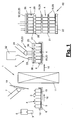
- FIG. 1 shows a schematic representation of a handling device (2) in a system (1).
- the plant (1) can be, for example, a bottle treatment plant in which new plastic bottles (3), in particular PET bottles, are produced and packaged.
- the empty bottles can also be filled and labeled with fluids, eg drinks.
- the bottle treatment plant (1) on the input side to a bottle maker, which is not shown for clarity.
- the bottles are transported via a suitable conveying means, eg an air conveyor, to a schematically indicated converter (6) which grips the bottles (3) individually or in rows and converts them to a carrier (8) of the handling device (2).
- the bottle maker, the converter (6) and the carrier (8) can, for example, according to the WO 99/55604 A1 or even the WO 00/69760 A1 be educated.
- the converter (6) may alternatively be an unpacker.
- the layer gripping device (23) described below may alternatively be designed as a row gripper and used as a converter (6).
- the carrier (8) has e.g. a trough shape and consists of a support bottom (9) and a side wall (10) on a plurality of carrier sides, wherein the side wall (10) is preferably arranged circumferentially.
- the carrier (8) can be arranged a conveyor (16) for its transport. If necessary, the carriers (8) can circulate in the system (1) or be reversibly moved.
- Part of the system (1) and possibly the handling device (2) can also be a bearing (11) for a plurality of carriers (8).
- the carriers (8) can circulate within the system (1) or the handling device (2).
- the bearing (11) can serve as a buffer point for the short-term inclusion of multiple carriers or trays (8). It can also be designed as a shelf storage or the like. With higher capacity. in the Bearing (11), which may be present several times, empty and / or filled bottles (3) can be stored.
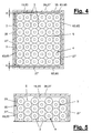
- FIGS. 4 and 5 show in a plan view different layer patterns.
- the rows of bottles are arranged in a regular matrix with straight rows in several rows along and across each other.
- the rows of bottles are mutually gaped and vernestet, with one bottle (3) in each of the two bottles (3) formed in the other row gusset dips.
- gaps (5) can arise between the bottles (3).
- These intermediate spaces (5) may be advantageous for the handling of the bottle layer (4) described below with a layer grasping device (23) and may be at least partially retained.
- guide means possibly entrained, e.g. a grid or the like are used for the bottles (3) in the intermediate spaces (5), but these are preferably not completely filled.
- the bottles (3) may be densely packed in the ply (4), the interspaces (5) being reduced in size.
- a movable and from the support (8) releasable intermediate bottom (19) may be arranged which rests flat or in places on the support base (9) and on which the fabric layer (4) is arranged.
- the area size of the intermediate bottom (19) essentially corresponds to the area size of the goods or bottle layer (4) and can be completed with the projected envelope edge of the bottle layer (4).
- the intermediate bottom (19) can also be slightly larger be and at one or more edges, preferably circumferentially, project laterally beyond the bottle layer (4).
- the handling device (2) has at least one layer grasping device (23) with which a bottle layer (4) is gripped and handled. This handling can be done in different ways.
- the layer gripping device (23) is designed and used as a palletizer (12).
- FIGS. 6 and 7 show a variant in which the layer gripping device (23) as Depalettierer (13) and possibly as a sliding device (14) is formed and used.
- the filled carriers (8) are unloaded with the palletizer (12) or the layer gripping device (23), the goods layer (4) together with the intermediate bottom (19) being gripped and palletized.
- a pallet stack (21) of a plurality of stacked goods or bottle layers (4) together with shelves (19) is formed on a pallet base (22).
- the pallet stack (21) is also referred to in short form as a pallet.
- the intermediate floors (19) form the usual pallets (21) intermediate layers (20).
- an intermediate bottom (19) which is also referred to as a bottom layer and which rests on the pallet base (22).
- the floor or intermediate layers (20) may have a uniform design and size. Subsequently, they are uniformly addressed as intermediate layers (20).
- the handling device (2) can have an insert (7) which can be placed in a suitable position, e.g. on the converter (6), is arranged and in the empty carrier (8) inserts an intermediate bottom (19).
- the shelves (19) or intermediate layers (20) may consist of any suitable material and may have any suitable shape. In the illustrated embodiment, they are formed as a flat plate in a rectangular shape and can be made of cardboard, plastic, metal or the like. Alternatively, they may have contoured surfaces, e.g. recessed receptacles for the bottoms and necks of bottles (3) or other parts of other goods (3).
- the intermediate floors (19) or intermediate layers (20) may alternatively or additionally have edge-side folds for position guidance. You can also have a substantially U- or H-shaped cross-section.
- the intermediate floors (19) or intermediate layers (20) can be largely rigid and wear the fabric layer (4) and support.
- the layer gripping device (23) has in each case a layer gripper (25) and a manipulator (24) for guiding it in the various exemplary embodiments.
- the manipulator (24) can have a plurality of rotary and / or translatory axes in any number and arrangement. It can be designed, for example, as a gantry robot with a plurality of linear axes or as an articulated-arm robot with a plurality of rotary axes.
- a support arm of the manipulator (24) is shown in each case schematically, which at the free end has a rigid or rotatable about at least one axis of rotation hand, which is suitably fixed or detachably connected to the sheet gripper (25).
- the layer gripper (25) is designed as a suction cup.
- the suction bell (25) engages in the various embodiments in each case the goods layer (4) together with the intermediate bottom (19) under the action of a vacuum formed in the interior of the suction bell (25).
- a suction device (32) is provided for its production. It has e.g. a possibly external and stationary vacuum generator, which is connected by means of flexible lines with a connection (33) on the suction bell (25) and which sucks the air located in the bell interior air.
- the vacuum generator (32) can also be arranged on the suction cup (25) and moved along.
- hood which may have a dome in the head area and in the lower region, for example, a circumferentially closed lateral hood wall (27), which leaves a hood opening (28) down.
- the hood wall (27) is formed by a plurality of side walls (27 ').
- the side walls (27 ') are dimensionally stable and consist of a suitably suitable material, for example plastic or metal.
- the dimensional stability can be so great that the side walls (27 ') do not deform or at least do not significantly deform by the negative pressure formed in the hood or bell interior and bulge inwards in contact with the fabric layer (4).
- the side walls (27 ') may be wholly or partially rigid and connected to a frame-like hood wall (27). Alternatively, they can be movable relative to one another, in particular displaceable and / or pivotable, in order to be able to adjust to different hood formats, in particular area sizes and shapes of the hood opening (28) with corresponding setting and control means.
- the side walls (27 ') are preferably airtight and prevent or at least minimize access of outside air through the wall into the hood interior. But it can alternatively also lateral openings, eg in a corner area, be present. In the simple embodiment shown, the side walls (27 ') are rigid and interconnected. They form at the bottom of a same height encircling hood edge (29).
- the suction bell (25) also has an internal and in the hood (26) arranged transversely lying head plate (31) which engages over the fabric layer (4).
- a layer receiving space (44) with the fabric layer (4) is formed below the top plate (31).
- the side hood wall (26) surrounds the layer receiving space (44).
- the suction cup (25) has an exhaust (39), which can be designed differently.
- a suction chamber (43) is formed above the top plate (31) .
- the suction (39) evacuates the layer receiving space (44) and generates here a negative pressure with which the fabric layer (4) and the intermediate bottom (19) or the intermediate layer (20) are sucked in and lifted.
- the head plate (31) can be permeable to air.
- the top plate (31) is e.g. formed as a grid or as a perforated plate with suction openings (40) and can flow the sucked air flow from the layer receiving space (44) to the suction chamber (43) and further to the terminal (33).
- the suction openings (40) can be the same size. Their size may alternatively vary as a whole or locally to realize different suction effects, which may also be locally different.
- the top plate (31) is in the embodiment of Figure 2,3 and 10.11 rigidly arranged in the hood (26). It covers the fabric layer (4) and the layer receiving space (44) and can reach up to the lateral hood wall (27).
- the head plate (31) arranged vertically adjustable and can be raised and lowered in the hood interior with a corresponding adjusting device (not shown), which has a controlled drive. This flexibility is indicated by arrows in FIG. 9 symbolizes.
- the suction cup (25) engages the fabric layer (4) together with an underlying movable bottom (19,20) with a negative pressure generated by suction, which is lower than the external ambient pressure.
- the fabric layer or bottle layer (4) between the sucked bottom (19,20) and the top plate (31) is held and clamped.
- the suction cup (25) holds the bottom (19,20) with negative pressure, with this also a clamping force for the bottle layer (4) can be created.
- the intermediate bottom (19) or the intermediate layer (20) together with the fabric layer (4) is sucked into the hood interior and raised, wherein the goods or bottle layer (4) abuts on the top plate on the top plate (31).
- the hood opening (28) is larger in this embodiment in its opening area than the area size of the fabric layer (4) and also larger than the area size of the intermediate bottom (19) and the intermediate layer (20).
- Between the hood edge (29) or the side walls (27 ') and the edges of the intermediate bottom (19,20) may be a free space (30) through which air is sucked from the outside, if necessary.
- This gap (30) can be kept so small be that the leakage air does not adversely affect the negative pressure or suction pressure in the hood interior.
- the vacuum generator (32) can be designed for a correspondingly large air flow. In this case, the intake airflows large volume and the pressure difference to the ambient pressure and the power consumption and the size of the vacuum generator (32) may be correspondingly low.
- the side walls (27 ') in the illustrated embodiment of FIGS. 2 and 3 smaller than the opening width of the carrier (8), so that the side walls (27 ') between the fabric layer (4) and the bottom (19) and the lateral support walls (10) can dip.
- Such a training is recommended if the lateral support walls (10) have a significant height.
- the hood (26) can also be placed on the support walls (10) with the insides of the side walls (27 ') and the side support walls (10) substantially in alignment.
- a centering aid can be supportive.
- FIG. 3 shows this intake position.
- the fabric layer (4) has in the layer receiving space on all sides a lateral distance from the hood wall (27), which forms a free space.
- a positioning or centering device (35) can be arranged, for example, on one or more side walls (27 ') and arranged with a suitable 'movable and eg strip-shaped actuator (63,64) laterally against one or more, in particular opposite Pressing edges of the fabric layer (4) and the fabric layer (4) within the hood (26) positioned, eg centered.
- FIG. 4 shows such a centering arrangement.
- the two lateral adjusting or centering elements (63) are extended and laterally guide the fabric layer (4).
- a hood (26) can also be adapted to different formats of product layers (4).
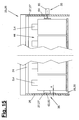
- FIG. 15 illustrates various embodiments of a positioning or centering device (35) in the broken half-section through a suction cup (25) or hood (26).
- the positioning or centering device (35) may consist, for example, according to the left half of the picture of one or more expandable control elements (63), which are designed for example as inflatable tubes.
- FIG. 15 shows the expanded working position with solid lines and the unpressurised or unloaded rest position in dashed form, wherein the distance (a) is shown.
- An expansion and / or increase in volume of variable-shape control elements (63) is also possible in other ways, for example by magnetic forces or electrostatic forces with changeable polarity.
- a continuous or interrupted bar can be arranged with a magnetic or electrostatic polarity and cooperate with an actuator (65), for example, as a generator of an electric or magnetic field with changeable polarity and optionally adjustable field strength or force, eg as a controllable electromagnet, can be formed and the force acting on the bar repulsive forces and possibly attracting forces generated.
- an actuator for example, as a generator of an electric or magnetic field with changeable polarity and optionally adjustable field strength or force, eg as a controllable electromagnet, can be formed and the force acting on the bar repulsive forces and possibly attracting forces generated.
- the positioning or centering device (35) may alternatively have inwardly movable strip-shaped adjusting elements (64) with a suitable mechanical actuator (65).
- the right half of FIG. 15 shows this arrangement.
- the adjusting elements (64) can be, for example, rigid or at least locally deformable clamping bars or the like.
- An actuator (65) may be formed, for example, as a cylinder, as an electric spindle, rack or scissor drive or the like.
- the positioning or centering device (35), in particular its (e) actuator (s) (65) can be controlled or regulated.
- Control is e.g. over the way and / or over the force, in particular the reaction force generated by the fabric layer (4) upon contact, possible.
- a measured value acquisition of a suitable control variable is e.g. by means of a pressure measurement, force measurement, distance or distance measurement, current or charge measurement or the like. Possible.
- a sensor (34) can be arranged in the hood interior or layer receiving space (44), which measures the pressure prevailing in the hood interior and which can be in communication with a control of the suction device (32).
- the controller may have a regulation for the vacuum generator (32), so that the hood internal pressure can be set to default values and optionally regulated.
- the hood internal pressure can be controlled or regulated to different values.
- the hood internal pressure is compared with the ambient pressure in a predetermined course, e.g. in a ramp, reduced, so that the suction and lifting of the bottle layer (4) and the bottom (19,20) takes place in a smooth movement.
- sucking air is sucked not only from the interior of the empty bottles (3), but also from the spaces (5), wherein on the bottles (3) inside and outside substantially the same pressure is applied and the bottle walls retain their shape.
- the inner pressure of the hood (26) can be gradually increased again, the fabric layer (4) and the bottom (19,20) turn in a smooth movement be lowered.
- the soft movements prevent negative mechanical influences on the fabric layer (4) and the bottles (3), which thereby retain their predetermined position and prevented from falling over or other undesirable changes in position.
- the centering device (35) can be loosened or possibly also deactivated.
- the suction cup (25) can transport the sucked product layer (4) and deliver it again at any point. During transport, the centering device (35) can be activated.
- a delivery of the goods or bottle layer (4) can eg FIG. 1 take place at a palletizing station (60).
- the hood edge (29) projects downwards a little above the sucked bottom (19,20).
- This supernatant can be used as a centering and also serves when slipping over the pallet base (22) or on an already palletized layer (4) as a limitation for sucked air leakage.
- the intermediate bottom (19) or the intermediate layer (20) can be placed directly on the bottom goods or bottle layer (4) in the stack (21). be put on.
- the floor (19, 20) can be kept floating at some distance above the already palletized fabric layer (4) by means of the suction bell (25), the vacuum in the hood (26) subsequently being gradually reduced, whereby the floor (19, FIG. 20) and the goods or bottle layer (4) is lowered until it rests on the palletizing stack (21).
- the suction cup (25) can be lifted from the settled goods or bottle layer (4) and moved to the loading point for receiving a new product layer (4).
- Figure 8,9 show a variant of Saugglöcke (25), in the hood opening is greater than the base of the goods or bottle layer (4) and can overlap this laterally.
- the intermediate bottom (19) or the intermediate layer (20) in the surface is larger than the hood opening (28), so that here again inserted between the side support walls (10) Habe (26) with its lower hood edge (29 ) gets up on the laterally over the layer (4) protruding bottom edge regions.
- negative pressure in the hood (26) of the bottom (19,20) against the hood edge (29) is pressed and held.
- the top plate (31) is lowered in this case.
- the lowering can be done so far until the top plate (31) rests on the top layer, here the bottle necks. In this position, the top plate (31) is fixed.
- the negative pressure applied holds the fabric layer (4), which is held by the bottom sucked on the bottom (19,20) down and clamped upwards from the top plate (31).
- a positioning and centering device (35) and a sensor (34) in the hood (26) may be arranged.
- the floor (19, 20) may be placed in the aforementioned manner on a ground, e.g. the top of the top pallet layer, be placed directly. It can alternatively be kept at a small vertical distance and lowered by gradual reduction of the hood vacuum together with the position (4).
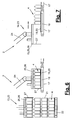
- FIGS. 6 and 7 show a Depalettierer (13), with a pallet stack (21) is dismantled and unloaded.
- the suction cup (25) may have the same configuration as in the embodiments described above and is put over the top layer (4) for depalletizing, wherein it can overlap the intermediate layer (20) or can stand up on the intermediate layer (20).
- FIG. 6 shows an embodiment of the above-described design of FIGS. 2 and 3 equivalent.
- the layer gripping device (23) sucks the goods or bottle layer (4) together with the intermediate layer (20) and transports them, while maintaining the suction pressure or negative pressure, up to a stationary or non-stationary delivery point, e.g. may be formed on a conveyor (17). These are e.g. around an intermittent conveyor, e.g. a belt conveyor.
- the goods or bottle layer (4) is deposited in the manner described above together with the intermediate layer (20) on the conveyor (17) and can then be transported on.
- FIGS. 6 and 7 illustrate a further variant in which the layer gripping device (23) is also designed as a sliding device (14), which allows separation of the goods or bottle layer (4) of the intermediate layer (20) at the delivery point.
- a holding device (18) is arranged at the delivery point, which is arranged below the conveyor (17), for example.
- the holding device (18) acts on the intermediate layer (20) and hold on to it.
- the holding device (18) can be designed for this purpose in any suitable manner, for example as a suction device.
- the suction cup (25) can have an additional function as a layer slide (15). If it is released after pressure equalization from the settled position (4), it can according to FIG. 7 moved behind the layer (4) and lowered again, wherein in a subsequent forward movement, the layer (4) through the rigid side walls (27 ') of the hood (26) from the detained bottom (19,20) deported and discharged, for example a subsequent further conveyor (17) for removing the layer (4).
- a separation of the layer (4) into individual rows or individual bottles or goods (3) take place.
- the empty intermediate floor (19) or the intermediate layer (20) can be disposed of in a suitable manner, for example, it is again taken up with the suction cup (25) and transported away. It can be dispensed on a stack or the like. It can alternatively be put back in a standing support (8).
- the suction cup (25) engages in each case a complete goods or bottle layer (4), wherein also the intermediate bottom (19) or the intermediate layer (20) receives a complete bottle position.
- the layer size may correspond to the receiving surface of a carrier (8) or a pallet stack (21).
- the above-described layer (4) may be a partial layer.
- the area size of a partial layer corresponds to the size of a pallet layer, wherein the carrier (8) has an oversize and can accommodate two or more such partial layers side by side. Accordingly, each partial layer also has its own intermediate bottom (19) or its intermediate layer (20).
- the carrier size is smaller than a pallet layer and insofar forms a partial position.
- Several such partial layers can be assembled side by side to form a pallet and palletized.
- depalletizing works in the same way.
- the floor size is adapted to the partial layer size.
- the term used in the embodiments of the product layer (4) also refers to such partial layers.
- mixed containers are produced in the pallet.
- This is e.g. for display pallets of advantage, which should present in each of their piled layers (4) one or more goods, especially bottles (3) of different varieties, such as different drinks, for sale and direct removal for customers.
- Such display pallets form at the point of sale, e.g. in a supermarket, the sales pile and replace a shelf.
- Such mixed containers in the pallet layers are also referred to as Rainbow containers.
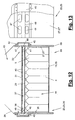
- FIGS. 12 and 13 show a variant of the layer gripping device (23) and the layer gripper or the suction cup (25) and the suction (39).
- This variant is eg able to receive a layer cover (37) in addition to the goods or bottle layer (4) and the optionally existing intermediate bottom (19, 20) and to form a gripping device (36) for this purpose.
- the hood opening (28) is also larger than the layer cover (37).
- the layer cover (37) may consist, for example, of an intermediate layer (20) and a cover (38) arranged thereon and lies on the fabric layer (4).
- the lid (38) may be formed as a top frame and as a narrow peripheral frame, which can serve to support a Stapelumreifung and the outside flush with the pallet contour. In the middle of the top frame (38) has a large opening, which may optionally be arranged stiffening struts.
- the shown layer gripping device (23) can also be used without such or other layer cover (37). It can also be used with a layer cover (37) and without a bottom or intermediate layer (19,20).
- the suction bell (25) can be formed as in the embodiments described above and be provided with a top plate (31) which has one or more suction openings (40) at least in the interior for the passage of air from the layer receiving space (44) into the suction chamber (43). having.
- the connection (33) for the vacuum generator (32) can also be arranged here on the dome or on the suction chamber (43) of the hood (26).
- the size adjustments of the hood opening (28) on the size of the layer (4) and the intermediate bottom (19) can be the same as in the variants of Figure 2,3 and 8.9 be.
- the suction (39) of the gripping device (36) or sheet gripping device (23) in FIGS. 12 and 13 a suction opening (41) in the lateral hood wall (27), which is located in the region of the layer receiving space (44) and opens here and can be acted upon from the outside with negative pressure.
- the suction opening (41) can be present multiple times and can be located on one or more side walls (27 '). Air can also be sucked out of the layer receiving space (44) via the suction opening (s) (41) and the layer receiving space (44) evacuated.
- the suction channel (46) starts from the suction opening or openings (41), leading out of the hood interior, out past a wall area (48) of the hood wall (27) and then to the suction space (43) with a mouth (47) ) connected.
- the suction channel (46) is formed, for example, by a convex cap (45) placed on the outside, which covers the wall openings (41, 47) and is connected, for example screwed, to the hood wall (27).
- the lateral bypass (42) on the hood (26) may be disposed on one or more side walls (27 '). In particular, it can surround the hood (26) in an annular manner.
- the suction opening (s) (41) and the mouth openings (47) can lie one above the other and be distanced from the web-like wall area (48). They can each lie in at least one row at a distance in Hauben peripheral vision in a row and can in particular have an elongated shape.
- a lying on the bottle layer (4) layer cover (37) comes when priming the fabric layer (4) into abutment with the here preferably stationary top plate (31) and covers the suction openings (40) down from.
- the one or more suction openings (41) lie at such a distance below the cover plate (31) that they are free when the sheet cover (37) is sucked in.
- the negative pressure prevailing in the suction chamber (43) acts on the bypass (42) further in the layer receiving space (44) and sucks the air located here, whereby the bottle layer (4) and possibly the intermediate bottom (19,20) sucked and in the contact position held on the sheet cover (37).
- the cover plate (31) is located in the height of the wall region (48) and can be fixed here if necessary.
- the top plate (31) solid and impermeable to air, wherein the layer receiving space (44) is evacuated via the bypass (42).
- Another variant provides, instead of or in addition to the top plate (31) a in FIG. 12 dashed lines indicated edge-like abutment stop (49) on the inside of the hood wall (27) to provide against which the ply cover (37) sets.
- the suction (39) shown by arranging a connection (33) on the suction opening (s) (41) in the hood wall (27) and thereby replacing a bypass (42) or possibly to complete.
- the suction opening (s) (41) can be connected to the existing or to an additional vacuum generator (32).
- in such a side suction (39) via one or more suction opening (s) (41) of the suction chamber (43) omitted.
- the bypass (42) may vary and may be disposed within the hood (26), for example.
- a bypass (not shown) can be formed, for example, in the edge region of an air-permeable top plate (31) reaching up to the hood wall (27).
- the top plate (31) may be larger than the suitably centered ply cover (37) on one or more sides, thereby forming one or more peripheral suction areas or suction gaps, where air is blown out of the ply space (44) adjacent the ply cover (37) ) can be sucked.
- the suction openings (40) in the cover plate (31) may be larger than in their inner region.
- An interrupted or otherwise air-permeable stop (49) can also form edge-side suction regions or suction gaps on the hood wall (27).
- FIG. 14 shows a variant of the bottle treatment plant (1) and the handling device (2) of FIG. 1 ,
- the handling device (2) here has a palletizer (12) and / or depalletizer (13), which is designed as a palletizing robot (58).
- the manipulator (24) is designed as a linear robot with multiple linear axes and carries the layer gripping device (23).
- the conveyors (16) are formed in the embodiment shown as reversing conveyors and extend with their preferably linear movement or conveyor track (52) transversely to the longitudinal axis of the palletizing robot (58) and its portal.
- the conveyor (16) can be single-storey or multi-storey, wherein trays (8) are arranged on several floors above one another and movable.
- the conveyor (16) may be structurally designed as a shuttle car.
- each tray conveyor (16) is here associated with a transfer robot (56), which in each case has a gantry robot with several linear axes and a multiaxially movable row gripper (57).
- the one or more Umsetzroboter (56) each extend over one or more conveyor tracks (52) of the tray conveyor (16) in the area of Umsetzroboters (56) have a working and positioning for a carrier (8).
- an insert (7) is arranged, which is designed as a loading robot (54) and which can also operate one or more tray conveyors (16), which have corresponding supply positions for a tray (8) in the robot working area.
- the infeed robot (54) is likewise embodied as a gantry robot with linear axes and has a multiaxially movable gripping tool (55) with which intermediate shelves (19) and / or intermediate layers or cover layers (20) are gripped by a provision and brought to the trays (8) can be.
- the inlay robot (54) can also pick up lids or top frames (38) from a stack and bring them to the carriers (8) and the product layers (4) there.
- the bottles (4) are fed by a conveyor (50) in one or more rows of the handling device (2).
- the transfer robot (56) takes over one or more rows with its row gripper (57) and places them on a provided support (8) into which the deposit robot (54) previously laid an intermediate floor (19).
- the carrier (8) moves into the ready position on the palletizing robot (58), which with its layer gripping device (23) picks up the goods or bottle layer (4) with the intermediate bottom (19) and to the palletizing station (60) transported and there the palette (21) builds.
- the empty carrier (8) moves back to the delivery position on the infeed robot (54) and picks up a new intermediate layer (19), after which it is moved to the ready position on the transfer robot (56) and loaded again with a bottle layer (4).
- the cycle then starts again.
- the tray first moves back to the depositing robot (54), which has a cover layer (20) and possibly a lid or lid Top Frame (38) hangs up. Only then is the tray (8) transported to the palletizing robot (58) and removed from this added to the completion of the pallet stack (21).
- the palletizing robot (58) can operate a plurality of tray conveyors (16) or trays (8) and several palletizing places (60), so that the processing times can be overlapped. If a tray (8) is being loaded with a bottle layer (4), the palletizing robot (58) can unload a meanwhile available other carrier (8) and form a pallet stack (21). A corresponding function results for the converter (6) and the insert (7).
- the pallet shelves (22) are provided by a pallet feeder (59) and brought to the palletizing places (60). This is followed by a conveyor (51) for the pallets (21). This can accommodate several loaded pallets (21) and can also have several possibly interconnected conveyor strands. An intermediate store or buffer (53) for palletized bottles (3) or other goods can hereby be formed on the conveyor (51).
- the handling device (2) can also be used as a depalletizer (13) in the manner described above, with which the returned pallets (21) are depalletized again, the bottles (3) being converted in rows by the converter onto the conveyor device (50).
- the pallet store (53) can be the tray warehouse (11) of FIG. 1 replace or may supplement such a tray warehouse (11) if necessary.
- a buffering or storage function is useful when a bottle maker located in plant 1, eg a blow molding machine (not shown), has a higher production capacity than a filling device (not shown) or has other process times.
- handling device (2) can also otherwise produced bottles (3), eg glass or new glass, supplied in palletized form and depalletized for subsequent filling and separated.
- bottles (3) eg glass or new glass
- an unpacking device (62) can be connected to the pallet conveyor (51).
- filled bottles can be palletized with the handling device (2) shown and stored or transported away after passing through a schematically indicated packaging device (61).
- the suction cup (25) may include other means, e.g. Sealing lips or the like. It can also be changeable to adapt to different shapes and sizes of the product layers (4). It can alternatively be adjustable in itself. For this purpose, for example, in the hood (26) partitions or the like. Be arranged to form smaller hood areas for partial layers. The hood areas can also be sealed off from one another by suction technology and can be individually controlled or regulated.
- the layer gripping device (23) can in a modification of FIG. 1 for unloading the carriers (8) and for delivering the layers (4) to a conveyor or a stationary delivery point. It forms an unloading device. Alternatively, it can also be used for loading carriers (8) with goods or bottle layers (4).
- the layer gripping device (23) can be used to any charge carriers, in particular boxes, lattice boxes, etc. with goods layers (4) together with intermediate layers (20) and possibly a layer cover (37), eg also a box or Box lid, to load and unload.
- a layer cover eg also a box or Box lid
- several product layers (4) can be stacked on top of each other.
- a carrier (8) may have one or more movable side walls (10) facilitating unloading and delivery of the suction cup (25).
- the carrier (8) can in the arrangement of Figure 2,3 and 8.9 for an external air access to the hood edge (29) and under the intermediate floor (19,20) are taken care of.
- the support bottom (9) can also be designed such that outside air can flow in under the intermediate bottom (19, 20) during lifting, for example by the support base (9) having a raised base, spacer ribs, knobs or the like.
- the suction cup (25) can also be held with a small distance above the support bottom (9). It can also have height-adjustable and, for example, telescopic side walls (27 ').
- hood adaptation to different heights of the fabric layer (4).
- hood edge (29) may be arranged a flexible element which deforms during suction to the intermediate bottom (19,20) out and closes the free space (3) and largely seals.
- the handling device (2) shown with the multi-axis converter (6) for row-wise gripping and defined transfer of bottles (3) on the carrier (8) and back has special advantages for the safe handling and management of the bottles (3).
- a carrier transport between a palletizer / depalletizer (12,13), a converter (6) and a depositor (7) the operation can be optimized.
- the layer gripping device (23) can also be used in conjunction with a conventional palletizer or depalletizer without a carrier.
- the goods, in particular bottles (3) can in the usual way be pushed over a row conveyor on a prepared intermediate layer (20) or brought in some other way, wherein gradually the layer (4) is formed.
- a conventional palletizing the use of the gripping device (36) according to the invention of FIGS. 12 and 13 for the common inclusion of a fabric layer (4) with intermediate layer (20) and layer cover (37) of advantage.
- a layer gripper or a suction cup (25) in the execution of FIGS. 2 and 3 in which the hood opening (28) is larger than the goods layer (4) and the intermediate layer (20), wherein the intermediate layer (20) is also imbibed into the hood interior or layer receiving space (44).
- the layer gripper (23) may be designed and arranged independently in their training as a palletizer (12) or as depalletizer (13) or as a sliding device (15) and also as a loader / unloader. It does not have to be part of the handling device (2) or the system (1) described at the beginning.
- the formation of the layer gripping device (23) has an independent inventive meaning.
- the layer gripping device (23) can grasp, transport and handle fabric layers (4) even without bottom or intermediate layer (20).
- the lateral hood wall (27) can also have a shortened height and does not have to extend to the bottom of the fabric layer (4).
- the layer gripping device (23) can also be used for the independent transport of an intermediate layer or bottom layer (20) and / or a layer cover (37) without a fabric layer (4). In this way, for palletizing a bottom layer (20) on the pallet base (22) placed first and then a sheet cover (37) gripped and immediately followed by a product layer (4) without bottom or intermediate layer (20) are picked and palletized. The same applies to depalletizing. On shelves (19) or intermediate layers (20) in carriers (8) and on an insert (7) for this can be dispensed with.
- the positioning or centering device (35) has independent inventive meaning and can also in other layer gripping means (23) with hood undersize compared to a bottom or intermediate layer (20) according to the embodiment of FIGS. 8 and 9 be used.
- the positioning or centering device (35) can also be used in conventional sheet gripping devices with suction cup, for example according to the US documents mentioned above.
- the handling device (2) with supports (8) and a layer gripping means (23) according to the embodiment of FIGS. 8 and 9 with the bottom or intermediate layer (19, 20) which can be sucked onto the hood edge (28), has independent inventive significance.
- a height-adjustable head plate (31) may be present.
Landscapes
- Engineering & Computer Science (AREA)
- Mechanical Engineering (AREA)
- De-Stacking Of Articles (AREA)
Claims (14)
- Dispositif de saisie de couche pour des couches de produits (4) composées de produits respectivement juxtaposés (3), en particulier de bouteilles, avec une cloche aspirante (25) pouvant coiffer une couche de produits (4), qui présente une hotte ouverte (26) avec une ouverture de hotte (28) et une aspiration (39), dans lequel la hotte (26) présente une chambre de réception de couche (44), une paroi de hotte (27) de forme stable entourant latéralement la chambre de réception de couche (44) et une ouverture de hotte (28) disposée sur le côté inférieur de la hotte, qui est plus grande que la couche de produits (4), caractérisé en ce que l'ouverture de hotte (28) est plus grande qu'une couche de base ou intermédiaire (20) se trouvant en dessous et/ou au-dessus de la couche de produits (4) et/ou qu'un recouvrement de couche (37), dans lequel la cloche aspirante (25) présente sur la paroi latérale de hotte (27) une dérivation (42), qui relie la chambre de réception de couche (44) en dessous d'une plaque de tête (31) ou d'une butée (49) de la cloche aspirante (25) avec une chambre d'aspiration (43) se trouvant au-dessus de celle-ci.
- Dispositif de saisie de couche selon la revendication 1, caractérisé en ce que le dispositif de saisie de couche (23) est réalisé sous forme de dispositif de saisie (36) pour une couche de produits (4) avec une couche de base ou une couche intermédiaire (20) et/ou un recouvrement de couche (37), dans lequel, lors de l'application d'une dépression dans la hotte (26), la couche de produits (4) et la couche de base ou la couche intermédiaire (20) et/ou le recouvrement de couche (37) sont aspirés dans la hotte (26).
- Dispositif de saisie de couche selon la revendication 1 ou 2, caractérisé en ce que le dispositif de saisie de couche (23) présente un générateur de dépression (32) réglable (33) raccordé à la hotte (26), en particulier disposé sur la cloche aspirante (25) et mobile avec elle, qui est relié à un capteur (34) dans la hotte (26) pour la détermination de la pression dans la hotte.
- Dispositif de saisie de couche selon l'une quelconque des revendications précédentes, caractérisé en ce que la cloche aspirante (25) présente une plaque de tête (31) interne à la hotte, saisissant la couche de produits reprise (4) et perméable à l'air et/ou une butée (49) interne à la hotte, saisissant en forme de cadre la couche de produits (4) et perméable à l'air.
- Dispositif de saisie de couche selon l'une quelconque des revendications précédentes, caractérisé en ce qu'une plaque de tête (31) interne à la hotte est réglable en hauteur.
- Dispositif de saisie de couche selon l'une quelconque des revendications précédentes, caractérisé en ce que la paroi latérale de hotte (27) présente plusieurs parois latérales (27') rigides ou mobiles, en particulier réglables.
- Dispositif de saisie de couche selon l'une quelconque des revendications précédentes, caractérisé en ce qu'un dispositif de positionnement ou de centrage (35) est disposé dans la hotte (26).
- Dispositif de saisie de couche selon la revendication 7, caractérisé en ce que le dispositif de positionnement ou de centrage (35) présente un ou plusieurs élément(s) de réglage (63, 64) mobile(s) et applicable(s) à une couche de produits reprise (4) avec un entraînement de réglage (65), dans lequel les éléments de réglage mobiles (63, 64) sont disposés, en particulier l'un en face de l'autre, sur le côté intérieur d'une ou de plusieurs paroi (s) latérale (s) (27).
- Dispositif de saisie de couche selon l'une quelconque des revendications 7 ou 8, caractérisé en ce que le dispositif de positionnement et de centrage (35) peut être commandé ou réglé, en particulier en ce qui concerne la course et/ou la force.
- Dispositif de saisie de couche selon l'une quelconque des revendications précédentes, caractérisé en ce que le dispositif de saisie de couche (23) présente un manipulateur (24) mobile suivant plusieurs axes et est réalisé sous forme de palettiseur (12) et/ou de dépalettiseur (13).
- Dispositif de saisie de couche selon l'une quelconque des revendications précédentes, caractérisé en ce que le dispositif de saisie de couche (23) est configuré pour des bouteilles vides (3), en particulier des bouteilles en plastique, ou pour des récipients parallélépipédiques.
- Dispositif de manipulation pour des produits (3), en particulier des bouteilles, avec un ou plusieurs support(s) (8) pour recevoir une couche de produits (4), caractérisé en ce que le dispositif de manipulation (2) présente un dispositif de saisie de couche (23) selon au moins une des revendications 1 à 11.
- Dispositif de manipulation selon la revendication 12, caractérisé en ce qu'un fond intermédiaire séparable (19) est disposé dans le support (8) en dessous de la couche de produits (4), dans lequel le dispositif de saisie de couche (23) saisit sous dépression la couche de produits (4) avec le fond intermédiaire (19) et le fond intermédiaire (19) est prévu comme couche intermédiaire (20) dans la pile de palettes (21).
- Procédé de manipulation de couches de produits (4) composées de produits respectivement juxtaposés (3), en particulier de bouteilles, avec un dispositif de saisie de couche (23), qui présente une cloche aspirante (25) avec une hotte ouverte (26) et une aspiration (39), qui coiffe la couche de produits (4) avec une ouverture de hotte (28) et qui maintient la couche de produits (4) avec une dépression, dans lequel la hotte (26) présente une chambre de réception de couche (44), une paroi de hotte (27) de forme stable, entourant latéralement la chambre de réception de couche (44) et une ouverture de hotte (28) disposée sur le côté inférieur de la hotte, qui est plus grande que la couche de produits (4), caractérisé en ce que l'ouverture de hotte (28) est plus grande qu'une couche de base ou intermédiaire (20) se trouvant en dessous et/ou au-dessus de la couche de produits (4) et/ou qu'un recouvrement de couche (37), dans lequel, lors de l'application d'une dépression dans la hotte (26), la couche de produits (4) et la couche de base ou intermédiaire (20) et/ou le recouvrement de couche (37) sont aspirés dans la hotte (26), et dans lequel la cloche aspirante (25) présente sur la paroi latérale de hotte (27) une dérivation (42), qui relie la chambre de réception de couche (44) en dessous d'une plaque de tête (31) ou d'une butée (49) de la cloche aspirante (25) avec une chambre d'aspiration (43) se trouvant au-dessus de celle-ci.
Applications Claiming Priority (3)
| Application Number | Priority Date | Filing Date | Title |
|---|---|---|---|
| DE202010005319 | 2010-04-28 | ||
| DE201020008173 DE202010008173U1 (de) | 2010-04-28 | 2010-07-28 | Handhabungseinrichtung |
| PCT/EP2011/056752 WO2011135031A1 (fr) | 2010-04-28 | 2011-04-28 | Dispositif de saisie de couches et dispositif de manipulation |
Publications (2)
| Publication Number | Publication Date |
|---|---|
| EP2563696A1 EP2563696A1 (fr) | 2013-03-06 |
| EP2563696B1 true EP2563696B1 (fr) | 2016-10-05 |
Family
ID=44310370
Family Applications (1)
| Application Number | Title | Priority Date | Filing Date |
|---|---|---|---|
| EP11718973.8A Not-in-force EP2563696B1 (fr) | 2010-04-28 | 2011-04-28 | Dispositif de saisie de couches et dispositif de manipulation |
Country Status (3)
| Country | Link |
|---|---|
| EP (1) | EP2563696B1 (fr) |
| DE (1) | DE202010008173U1 (fr) |
| WO (1) | WO2011135031A1 (fr) |
Cited By (1)
| Publication number | Priority date | Publication date | Assignee | Title |
|---|---|---|---|---|
| DE102021125893A1 (de) | 2021-10-06 | 2023-04-06 | Krones Aktiengesellschaft | Vorrichtung zum Depalletieren von Behältnislagen, Verwendung einer Vorrichtung zum Depalletieren von Behältnislagen und Verfahren zum Depalletieren von Behältnislagen |
Families Citing this family (8)
| Publication number | Priority date | Publication date | Assignee | Title |
|---|---|---|---|---|
| FR2983462B1 (fr) * | 2011-12-06 | 2015-08-07 | Packetis | Manipulation d'un ensemble compact d'une pluralite d'objets comme des produits de cartonnerie tels que des flans ou des boitages plies sur eux-memes. |
| DE102016107384B4 (de) | 2016-04-21 | 2019-11-21 | Martinmechanic Friedrich Martin Gmbh & Co. Kg | Entstapeleinrichtung zum lageweisen Entstapeln von Transportpaletten mit durch oder ohne durch Zwischenlagen getrennten Stapellagen |
| IT201700101371A1 (it) * | 2017-09-11 | 2019-03-11 | Ocme Srl | Organo di presa di uno strato di prodotti. |
| US11629009B2 (en) * | 2021-07-14 | 2023-04-18 | Newteq Holding B.V. | Automated warehouse systems, assemblies, apparatuses, and methods for assembling mixed pallets and facilitating order picking |
| DE102021132816A1 (de) | 2021-12-13 | 2023-06-15 | Krones Aktiengesellschaft | Vorrichtung zum Handhaben von Leerdosenlagen und Verfahren zum Handhaben von Leerdosenlagen |
| IT202200012140A1 (it) * | 2022-06-08 | 2023-12-08 | Flexlink Systems S P A | Dispositivo per il prelievo di prodotti impilati e metodo per prelevare prodotti impilati su pallet |
| DE102022131001A1 (de) * | 2022-11-23 | 2024-05-23 | Syntegon Technology Gmbh | Vorrichtung zum Entnehmen von pharmazeutischen Einzelbehältnissen aus einem wannenförmigen Transportbehälter, ein System umfassend eine entsprechende Vorrichtung und ein Verfahren zum Entnehmen von pharmazeutischen Einzelbehältnissen aus einem wannenförmigen Transportbehälter |
| DE102024116612A1 (de) * | 2024-06-13 | 2025-12-18 | Focke & Co. (Gmbh & Co. Kg) | Verfahren und Anlage zum Befüllen von Kartonpackungen und Anordnen auf einer Palette |
Family Cites Families (20)
| Publication number | Priority date | Publication date | Assignee | Title |
|---|---|---|---|---|
| GB1164766A (en) * | 1968-04-01 | 1969-09-24 | Alvey Conveyor Mfg Company | Pallet loading and unloading apparatus |
| FR2166242B1 (fr) * | 1972-01-03 | 1976-01-16 | Applic Procedes Electriq Fr | |
| DE2330204A1 (de) * | 1973-06-14 | 1975-01-09 | Thermak Gmbh & Co Kg | Foerdervorrichtung fuer plattenfoermiges gut |
| DE2338574A1 (de) | 1973-07-30 | 1975-02-20 | Allg Strassenbaubedarfs Gmbh | Verfahren und vorrichtung zum abfoerdern und lagern von insbesondere betonsteinen aus einer steinformmaschine |
| DE3009361A1 (de) | 1980-03-12 | 1981-09-24 | Nütro Patentverwertungs- u. Maschinen-Handels-Gesellschaft mbH, 8500 Nürnberg | Vorrichtung zum palettieren |
| FR2519619B1 (fr) * | 1982-01-11 | 1986-02-21 | Carnaud Emballage Sa | Procede et dispositif de prehension par aspiration |
| IT1176164B (it) * | 1984-05-22 | 1987-08-18 | Bini & C Srl | Procedimento ed apparecchiatura per il sollevamento ed il trasporto di oggetti sistemati su supporti a vassoio o simili |
| FR2579190B1 (fr) * | 1985-03-21 | 1988-10-14 | Thibault Jacques | Dispositif de levage de charges en couches formees d'objets independants les uns des autres et disposes cote a cote |
| EP0269566B1 (fr) * | 1986-11-10 | 1990-06-13 | Haas-Laser Systems AG | Dispositif de transport pour objets plats perforés |
| US4753564A (en) * | 1987-01-23 | 1988-06-28 | Goldco Industries, Inc. | Apparatus and method for effecting movement of selected tiers of stacked articles using pressure differentials |
| US5727832A (en) * | 1995-12-12 | 1998-03-17 | Abb Flexible Automation, Inc. | End effector for transferring articles |
| US5733100A (en) * | 1996-10-09 | 1998-03-31 | Plastipak Packaging, Inc. | Cylindrical object palletizer |
| EP1073598B1 (fr) | 1998-04-23 | 2001-09-05 | Certus Maschinenbau GmbH | Dispositif pour le traitement de bouteilles |
| DE29908766U1 (de) | 1999-05-18 | 2000-09-28 | Certus Maschinenbau GmbH, 86316 Friedberg | Vorrichtung zum Behandeln von Flaschen |
| DE20021874U1 (de) | 2000-12-29 | 2002-07-04 | KRONES AG, 93073 Neutraubling | Vorrichtung zum schichtenweisen Be- und Entpalettieren von Paletten mit Artikeln |
| US7481472B2 (en) * | 2005-03-15 | 2009-01-27 | Sage Automation, Inc. | Layer picking end effector system, apparatus and method |
| DE102006053694A1 (de) * | 2006-11-13 | 2008-05-15 | Müller, Hermann | Vorrichtung zum Palettieren und Depalettieren von Waren mit einem Palettiergreifer |
| US20080193272A1 (en) | 2007-02-08 | 2008-08-14 | Sage Automation, Inc. | Process for depalletizing goods |
| DE102008020486B4 (de) | 2008-04-23 | 2018-08-09 | Krones Aktiengesellschaft | Vorrichtung und Verfahren zum Palettieren von Stückgutzusammenstellungen |
| US9469490B2 (en) | 2008-08-06 | 2016-10-18 | Dyco, Inc. | Apparatus and method of palletizing loose-piece articles |
-
2010
- 2010-07-28 DE DE201020008173 patent/DE202010008173U1/de not_active Expired - Lifetime
-
2011
- 2011-04-28 WO PCT/EP2011/056752 patent/WO2011135031A1/fr not_active Ceased
- 2011-04-28 EP EP11718973.8A patent/EP2563696B1/fr not_active Not-in-force
Cited By (1)
| Publication number | Priority date | Publication date | Assignee | Title |
|---|---|---|---|---|
| DE102021125893A1 (de) | 2021-10-06 | 2023-04-06 | Krones Aktiengesellschaft | Vorrichtung zum Depalletieren von Behältnislagen, Verwendung einer Vorrichtung zum Depalletieren von Behältnislagen und Verfahren zum Depalletieren von Behältnislagen |
Also Published As
| Publication number | Publication date |
|---|---|
| EP2563696A1 (fr) | 2013-03-06 |
| WO2011135031A1 (fr) | 2011-11-03 |
| DE202010008173U1 (de) | 2011-11-14 |
Similar Documents
| Publication | Publication Date | Title |
|---|---|---|
| EP2563696B1 (fr) | Dispositif de saisie de couches et dispositif de manipulation | |
| AT522558B1 (de) | Depalettieranordnung mit einer Vorrichtung zum Depalettieren von stapelbaren Stückgutgebinden und Verfahren zum Depalettieren von stapelbaren Stückgutgebinden | |
| EP2330060B1 (fr) | Procédé et dispositif destinés au commissionnement automatisé de groupe de produits | |
| EP2144831B1 (fr) | Procédé pour charger et décharger une palette et palettiseuse correspondante | |
| EP3110731B1 (fr) | Procédé d'empilage | |
| DE102007016727B4 (de) | Verfahren zum mehrlagigen Bestapeln eines Trägers | |
| DE102013021533B4 (de) | Vorrichtung zum Beladen eines Ladungsträgers wie Palette oder dergleichen | |
| EP2125587B1 (fr) | Dispositif et procede de transfert de marchandises de detail | |
| WO2020094336A1 (fr) | Système de stockage et de récupération automatisé | |
| DE102008046325A1 (de) | Verfahren und Vorrichtung zum mannlosen, vollautomatisierten Kommissionieren von Artikeln in Auftragsladehilfsmittel | |
| US12246933B2 (en) | Stacking apparatus and stacking method | |
| EP2762428B1 (fr) | Procédé et dispositif de palettisation de couches de produits, d'articles et/ou de récipients | |
| DE202013103400U1 (de) | Handlingeinrichtung | |
| DE102011088849A1 (de) | Verfahren und Vorrichtung zum Palettieren von Artikellagen auf einem Stapelplatz | |
| EP2953873A1 (fr) | Système de palettisation | |
| EP1620338B1 (fr) | Procede et dispositif pour manoeuvrer des objets en forme de tiges | |
| DE102020112865A1 (de) | Einrichtung, System und Verfahren zur Lagerung und Kommissionierung von Gegenständen | |
| DE202008010273U1 (de) | Behälter und Verpackungseinrichtung | |
| DE102023102493A1 (de) | Stapeleinrichtung und Stapelverfahren | |
| EP4282794B1 (fr) | Dispositif et procédé d'empilement | |
| EP4527570A1 (fr) | Tête de préhension comprenant plusieurs pinces d'aspiration, ensemble de levage comprenant une telle tête de préhension et procédé de détection d'unités d'emballage | |
| DE29807325U1 (de) | Vorrichtung zum Sammeln und Palettieren von Flaschen |
Legal Events
| Date | Code | Title | Description |
|---|---|---|---|
| PUAI | Public reference made under article 153(3) epc to a published international application that has entered the european phase |
Free format text: ORIGINAL CODE: 0009012 |
|
| 17P | Request for examination filed |
Effective date: 20121128 |
|
| AK | Designated contracting states |
Kind code of ref document: A1 Designated state(s): AL AT BE BG CH CY CZ DE DK EE ES FI FR GB GR HR HU IE IS IT LI LT LU LV MC MK MT NL NO PL PT RO RS SE SI SK SM TR |
|
| DAX | Request for extension of the european patent (deleted) | ||
| 17Q | First examination report despatched |
Effective date: 20140313 |
|
| GRAP | Despatch of communication of intention to grant a patent |
Free format text: ORIGINAL CODE: EPIDOSNIGR1 |
|
| INTG | Intention to grant announced |
Effective date: 20160512 |
|
| GRAS | Grant fee paid |
Free format text: ORIGINAL CODE: EPIDOSNIGR3 |
|
| GRAA | (expected) grant |
Free format text: ORIGINAL CODE: 0009210 |
|
| AK | Designated contracting states |
Kind code of ref document: B1 Designated state(s): AL AT BE BG CH CY CZ DE DK EE ES FI FR GB GR HR HU IE IS IT LI LT LU LV MC MK MT NL NO PL PT RO RS SE SI SK SM TR |
|
| REG | Reference to a national code |
Ref country code: GB Ref legal event code: FG4D Free format text: NOT ENGLISH |
|
| REG | Reference to a national code |
Ref country code: CH Ref legal event code: EP |
|
| REG | Reference to a national code |
Ref country code: AT Ref legal event code: REF Ref document number: 834441 Country of ref document: AT Kind code of ref document: T Effective date: 20161015 |
|
| REG | Reference to a national code |
Ref country code: IE Ref legal event code: FG4D Free format text: LANGUAGE OF EP DOCUMENT: GERMAN |
|
| REG | Reference to a national code |
Ref country code: DE Ref legal event code: R096 Ref document number: 502011010836 Country of ref document: DE |
|
| REG | Reference to a national code |
Ref country code: NL Ref legal event code: MP Effective date: 20161005 |
|
| REG | Reference to a national code |
Ref country code: LT Ref legal event code: MG4D |
|
| PG25 | Lapsed in a contracting state [announced via postgrant information from national office to epo] |
Ref country code: LV Free format text: LAPSE BECAUSE OF FAILURE TO SUBMIT A TRANSLATION OF THE DESCRIPTION OR TO PAY THE FEE WITHIN THE PRESCRIBED TIME-LIMIT Effective date: 20161005 |
|
| REG | Reference to a national code |
Ref country code: FR Ref legal event code: PLFP Year of fee payment: 7 |
|
| PG25 | Lapsed in a contracting state [announced via postgrant information from national office to epo] |
Ref country code: SE Free format text: LAPSE BECAUSE OF FAILURE TO SUBMIT A TRANSLATION OF THE DESCRIPTION OR TO PAY THE FEE WITHIN THE PRESCRIBED TIME-LIMIT Effective date: 20161005 Ref country code: GR Free format text: LAPSE BECAUSE OF FAILURE TO SUBMIT A TRANSLATION OF THE DESCRIPTION OR TO PAY THE FEE WITHIN THE PRESCRIBED TIME-LIMIT Effective date: 20170106 Ref country code: NO Free format text: LAPSE BECAUSE OF FAILURE TO SUBMIT A TRANSLATION OF THE DESCRIPTION OR TO PAY THE FEE WITHIN THE PRESCRIBED TIME-LIMIT Effective date: 20170105 Ref country code: LT Free format text: LAPSE BECAUSE OF FAILURE TO SUBMIT A TRANSLATION OF THE DESCRIPTION OR TO PAY THE FEE WITHIN THE PRESCRIBED TIME-LIMIT Effective date: 20161005 |
|
| PG25 | Lapsed in a contracting state [announced via postgrant information from national office to epo] |
Ref country code: PT Free format text: LAPSE BECAUSE OF FAILURE TO SUBMIT A TRANSLATION OF THE DESCRIPTION OR TO PAY THE FEE WITHIN THE PRESCRIBED TIME-LIMIT Effective date: 20170206 Ref country code: IS Free format text: LAPSE BECAUSE OF FAILURE TO SUBMIT A TRANSLATION OF THE DESCRIPTION OR TO PAY THE FEE WITHIN THE PRESCRIBED TIME-LIMIT Effective date: 20170205 Ref country code: RS Free format text: LAPSE BECAUSE OF FAILURE TO SUBMIT A TRANSLATION OF THE DESCRIPTION OR TO PAY THE FEE WITHIN THE PRESCRIBED TIME-LIMIT Effective date: 20161005 Ref country code: NL Free format text: LAPSE BECAUSE OF FAILURE TO SUBMIT A TRANSLATION OF THE DESCRIPTION OR TO PAY THE FEE WITHIN THE PRESCRIBED TIME-LIMIT Effective date: 20161005 Ref country code: ES Free format text: LAPSE BECAUSE OF FAILURE TO SUBMIT A TRANSLATION OF THE DESCRIPTION OR TO PAY THE FEE WITHIN THE PRESCRIBED TIME-LIMIT Effective date: 20161005 Ref country code: PL Free format text: LAPSE BECAUSE OF FAILURE TO SUBMIT A TRANSLATION OF THE DESCRIPTION OR TO PAY THE FEE WITHIN THE PRESCRIBED TIME-LIMIT Effective date: 20161005 Ref country code: FI Free format text: LAPSE BECAUSE OF FAILURE TO SUBMIT A TRANSLATION OF THE DESCRIPTION OR TO PAY THE FEE WITHIN THE PRESCRIBED TIME-LIMIT Effective date: 20161005 Ref country code: HR Free format text: LAPSE BECAUSE OF FAILURE TO SUBMIT A TRANSLATION OF THE DESCRIPTION OR TO PAY THE FEE WITHIN THE PRESCRIBED TIME-LIMIT Effective date: 20161005 |
|
| REG | Reference to a national code |
Ref country code: DE Ref legal event code: R097 Ref document number: 502011010836 Country of ref document: DE |
|
| PG25 | Lapsed in a contracting state [announced via postgrant information from national office to epo] |
Ref country code: CZ Free format text: LAPSE BECAUSE OF FAILURE TO SUBMIT A TRANSLATION OF THE DESCRIPTION OR TO PAY THE FEE WITHIN THE PRESCRIBED TIME-LIMIT Effective date: 20161005 Ref country code: EE Free format text: LAPSE BECAUSE OF FAILURE TO SUBMIT A TRANSLATION OF THE DESCRIPTION OR TO PAY THE FEE WITHIN THE PRESCRIBED TIME-LIMIT Effective date: 20161005 Ref country code: DK Free format text: LAPSE BECAUSE OF FAILURE TO SUBMIT A TRANSLATION OF THE DESCRIPTION OR TO PAY THE FEE WITHIN THE PRESCRIBED TIME-LIMIT Effective date: 20161005 Ref country code: SK Free format text: LAPSE BECAUSE OF FAILURE TO SUBMIT A TRANSLATION OF THE DESCRIPTION OR TO PAY THE FEE WITHIN THE PRESCRIBED TIME-LIMIT Effective date: 20161005 Ref country code: RO Free format text: LAPSE BECAUSE OF FAILURE TO SUBMIT A TRANSLATION OF THE DESCRIPTION OR TO PAY THE FEE WITHIN THE PRESCRIBED TIME-LIMIT Effective date: 20161005 |
|
| PLBE | No opposition filed within time limit |
Free format text: ORIGINAL CODE: 0009261 |
|
| STAA | Information on the status of an ep patent application or granted ep patent |
Free format text: STATUS: NO OPPOSITION FILED WITHIN TIME LIMIT |
|
| PG25 | Lapsed in a contracting state [announced via postgrant information from national office to epo] |
Ref country code: IT Free format text: LAPSE BECAUSE OF FAILURE TO SUBMIT A TRANSLATION OF THE DESCRIPTION OR TO PAY THE FEE WITHIN THE PRESCRIBED TIME-LIMIT Effective date: 20161005 Ref country code: SM Free format text: LAPSE BECAUSE OF FAILURE TO SUBMIT A TRANSLATION OF THE DESCRIPTION OR TO PAY THE FEE WITHIN THE PRESCRIBED TIME-LIMIT Effective date: 20161005 Ref country code: BG Free format text: LAPSE BECAUSE OF FAILURE TO SUBMIT A TRANSLATION OF THE DESCRIPTION OR TO PAY THE FEE WITHIN THE PRESCRIBED TIME-LIMIT Effective date: 20170105 |
|
| 26N | No opposition filed |
Effective date: 20170706 |
|
| PG25 | Lapsed in a contracting state [announced via postgrant information from national office to epo] |
Ref country code: SI Free format text: LAPSE BECAUSE OF FAILURE TO SUBMIT A TRANSLATION OF THE DESCRIPTION OR TO PAY THE FEE WITHIN THE PRESCRIBED TIME-LIMIT Effective date: 20161005 |
|
| REG | Reference to a national code |
Ref country code: CH Ref legal event code: PL |
|
| REG | Reference to a national code |
Ref country code: IE Ref legal event code: MM4A |
|
| PG25 | Lapsed in a contracting state [announced via postgrant information from national office to epo] |
Ref country code: MC Free format text: LAPSE BECAUSE OF FAILURE TO SUBMIT A TRANSLATION OF THE DESCRIPTION OR TO PAY THE FEE WITHIN THE PRESCRIBED TIME-LIMIT Effective date: 20161005 |
|
| PG25 | Lapsed in a contracting state [announced via postgrant information from national office to epo] |
Ref country code: LI Free format text: LAPSE BECAUSE OF NON-PAYMENT OF DUE FEES Effective date: 20170430 Ref country code: LU Free format text: LAPSE BECAUSE OF NON-PAYMENT OF DUE FEES Effective date: 20170428 Ref country code: CH Free format text: LAPSE BECAUSE OF NON-PAYMENT OF DUE FEES Effective date: 20170430 |
|
| REG | Reference to a national code |
Ref country code: BE Ref legal event code: MM Effective date: 20170430 |
|
| REG | Reference to a national code |
Ref country code: FR Ref legal event code: PLFP Year of fee payment: 8 |
|
| PG25 | Lapsed in a contracting state [announced via postgrant information from national office to epo] |
Ref country code: IE Free format text: LAPSE BECAUSE OF NON-PAYMENT OF DUE FEES Effective date: 20170428 |
|
| PG25 | Lapsed in a contracting state [announced via postgrant information from national office to epo] |
Ref country code: BE Free format text: LAPSE BECAUSE OF NON-PAYMENT OF DUE FEES Effective date: 20170430 |
|
| REG | Reference to a national code |
Ref country code: AT Ref legal event code: MM01 Ref document number: 834441 Country of ref document: AT Kind code of ref document: T Effective date: 20170428 |
|
| PG25 | Lapsed in a contracting state [announced via postgrant information from national office to epo] |
Ref country code: AT Free format text: LAPSE BECAUSE OF NON-PAYMENT OF DUE FEES Effective date: 20170428 |
|
| PG25 | Lapsed in a contracting state [announced via postgrant information from national office to epo] |
Ref country code: MT Free format text: LAPSE BECAUSE OF FAILURE TO SUBMIT A TRANSLATION OF THE DESCRIPTION OR TO PAY THE FEE WITHIN THE PRESCRIBED TIME-LIMIT Effective date: 20161005 |
|
| PG25 | Lapsed in a contracting state [announced via postgrant information from national office to epo] |
Ref country code: HU Free format text: LAPSE BECAUSE OF FAILURE TO SUBMIT A TRANSLATION OF THE DESCRIPTION OR TO PAY THE FEE WITHIN THE PRESCRIBED TIME-LIMIT; INVALID AB INITIO Effective date: 20110428 |
|
| PG25 | Lapsed in a contracting state [announced via postgrant information from national office to epo] |
Ref country code: CY Free format text: LAPSE BECAUSE OF NON-PAYMENT OF DUE FEES Effective date: 20161005 |
|
| PG25 | Lapsed in a contracting state [announced via postgrant information from national office to epo] |
Ref country code: MK Free format text: LAPSE BECAUSE OF FAILURE TO SUBMIT A TRANSLATION OF THE DESCRIPTION OR TO PAY THE FEE WITHIN THE PRESCRIBED TIME-LIMIT Effective date: 20161005 |
|
| PG25 | Lapsed in a contracting state [announced via postgrant information from national office to epo] |
Ref country code: TR Free format text: LAPSE BECAUSE OF FAILURE TO SUBMIT A TRANSLATION OF THE DESCRIPTION OR TO PAY THE FEE WITHIN THE PRESCRIBED TIME-LIMIT Effective date: 20161005 |
|
| PG25 | Lapsed in a contracting state [announced via postgrant information from national office to epo] |
Ref country code: AL Free format text: LAPSE BECAUSE OF FAILURE TO SUBMIT A TRANSLATION OF THE DESCRIPTION OR TO PAY THE FEE WITHIN THE PRESCRIBED TIME-LIMIT Effective date: 20161005 |
|
| PGFP | Annual fee paid to national office [announced via postgrant information from national office to epo] |
Ref country code: GB Payment date: 20220425 Year of fee payment: 12 Ref country code: FR Payment date: 20220421 Year of fee payment: 12 Ref country code: DE Payment date: 20220516 Year of fee payment: 12 |
|
| REG | Reference to a national code |
Ref country code: DE Ref legal event code: R119 Ref document number: 502011010836 Country of ref document: DE |
|
| GBPC | Gb: european patent ceased through non-payment of renewal fee |
Effective date: 20230428 |
|
| PG25 | Lapsed in a contracting state [announced via postgrant information from national office to epo] |
Ref country code: GB Free format text: LAPSE BECAUSE OF NON-PAYMENT OF DUE FEES Effective date: 20230428 |
|
| PG25 | Lapsed in a contracting state [announced via postgrant information from national office to epo] |
Ref country code: GB Free format text: LAPSE BECAUSE OF NON-PAYMENT OF DUE FEES Effective date: 20230428 Ref country code: FR Free format text: LAPSE BECAUSE OF NON-PAYMENT OF DUE FEES Effective date: 20230430 Ref country code: DE Free format text: LAPSE BECAUSE OF NON-PAYMENT OF DUE FEES Effective date: 20231103 |