EP2563714B1 - Zapfkopf für ein getränkeausgabesystem unter druck - Google Patents
Zapfkopf für ein getränkeausgabesystem unter druck Download PDFInfo
- Publication number
- EP2563714B1 EP2563714B1 EP11716921.9A EP11716921A EP2563714B1 EP 2563714 B1 EP2563714 B1 EP 2563714B1 EP 11716921 A EP11716921 A EP 11716921A EP 2563714 B1 EP2563714 B1 EP 2563714B1
- Authority
- EP
- European Patent Office
- Prior art keywords
- dispense head
- piston
- beverage container
- sealing
- spear
- Prior art date
- Legal status (The legal status is an assumption and is not a legal conclusion. Google has not performed a legal analysis and makes no representation as to the accuracy of the status listed.)
- Not-in-force
Links
- 235000013361 beverage Nutrition 0.000 title claims description 88
- 238000007789 sealing Methods 0.000 claims description 63
- 230000004913 activation Effects 0.000 claims description 17
- 239000012530 fluid Substances 0.000 claims description 16
- 239000013013 elastic material Substances 0.000 claims description 4
- 238000006073 displacement reaction Methods 0.000 description 4
- 238000005187 foaming Methods 0.000 description 2
- 239000000463 material Substances 0.000 description 2
- 239000002184 metal Substances 0.000 description 2
- 208000003443 Unconsciousness Diseases 0.000 description 1
- 238000001816 cooling Methods 0.000 description 1
- 230000002498 deadly effect Effects 0.000 description 1
- 231100001261 hazardous Toxicity 0.000 description 1
- 238000004519 manufacturing process Methods 0.000 description 1
- 238000012986 modification Methods 0.000 description 1
- 230000004048 modification Effects 0.000 description 1
- 230000002265 prevention Effects 0.000 description 1
- 230000029058 respiratory gaseous exchange Effects 0.000 description 1
Images










Classifications
-
- B—PERFORMING OPERATIONS; TRANSPORTING
- B67—OPENING, CLOSING OR CLEANING BOTTLES, JARS OR SIMILAR CONTAINERS; LIQUID HANDLING
- B67D—DISPENSING, DELIVERING OR TRANSFERRING LIQUIDS, NOT OTHERWISE PROVIDED FOR
- B67D1/00—Apparatus or devices for dispensing beverages on draught
- B67D1/08—Details
- B67D1/0829—Keg connection means
- B67D1/0831—Keg connection means combined with valves
-
- B—PERFORMING OPERATIONS; TRANSPORTING
- B67—OPENING, CLOSING OR CLEANING BOTTLES, JARS OR SIMILAR CONTAINERS; LIQUID HANDLING
- B67D—DISPENSING, DELIVERING OR TRANSFERRING LIQUIDS, NOT OTHERWISE PROVIDED FOR
- B67D1/00—Apparatus or devices for dispensing beverages on draught
- B67D1/08—Details
-
- B—PERFORMING OPERATIONS; TRANSPORTING
- B67—OPENING, CLOSING OR CLEANING BOTTLES, JARS OR SIMILAR CONTAINERS; LIQUID HANDLING
- B67D—DISPENSING, DELIVERING OR TRANSFERRING LIQUIDS, NOT OTHERWISE PROVIDED FOR
- B67D1/00—Apparatus or devices for dispensing beverages on draught
- B67D1/08—Details
- B67D1/12—Flow or pressure control devices or systems, e.g. valves, gas pressure control, level control in storage containers
- B67D1/125—Safety means, e.g. over-pressure valves
Definitions
- the present invention relates to a dispense head adapted to be coupled to a beverage container above a spear arranged in the beverage container in a dispensing system, the dispense head comprising a piston arranged axially displaceable within a housing, the piston being connected to a handle so that upon activation of the handle, the piston will be displaced axially towards the spear, whereby a top part of the spear will be forced downwards, causing it to open the beverage container, a gas inlet arranged in the housing, which is in fluid communication with a space extending along the piston, the space being sealed at least at a top end with a first sealing and at a bottom end with a second sealing.
- the present invention also relates to a dispensing system.
- the beverage is stored in a container, such as a keg, which is connected to a dispensing system during use.
- the beverage flows from the container through a dispensing line which is typically connected to a dispensing tap where the beverage is dispensed.
- the flow of beverage may for instance be achieved by a higher than atmospheric pressure inside the container, forcing the beverage into the dispensing line.
- pressure is usually continuously applied to the inside of the container by means of a pressure medium. It is common to use CO2 as the pressure medium.
- the pressure medium is usually supplied to the beverage container from a gas cylinder via a dispense head. Also, it is common that the dispense head connects to the beverage outlet of the container, whereby it serves to supply pressure medium, such as CO2, to the beverage container and beverage to the dispensing system.
- pressure medium such as CO2
- the pressure medium flow is connected to the dispense head first, and subsequently the beverage flow is connected.
- One drawback of this is that it entails a risk of foaming once the beverage flow is connected, which is at best messy and at worst dangerous for the user if the pressure is high enough to cause equipment failure.
- a dispense head which is inexpensive to manufacture and simple yet provides a satisfactory prevention of pressure medium leakage and foaming.
- CO2 is a hazardous gas if the total content of gas in a room becomes too high. Normal concentration of CO2 in the atmosphere is 0.03 Vol.-%. If the amount of CO2 reaches a level of 2 to 3 Vol.-%, the people in the room will experience higher respiration and higher pulse frequency. This will increase with the increasing level of CO2 and end up in unconsciousness. If the level exceeds 10 Vol.-%, it is deadly, even if the people in the room are exposed for only a short period of time.
- CO2 is an expensive gas, and thus, leakage of the gas may also be a costly affair.
- a dispense head according to the preamble of claim 1 is known from US-A-4 450 853 .
- the dispense head comprising a piston arranged axially displaceable within a housing, the piston being connected to a handle so that upon activation of the handle, the piston will be displaced axially towards the spear, whereby a top part of the spear will be forced downwards, causing it to open the beverage container, a gas inlet arranged in the housing, which is in fluid communication with a space, which space is extending along the piston, the space being sealed at least at a top end with a first sealing and at a bottom end with a second sealing, wherein positioning means is arranged in connection with the piston, enabling the first sealing and the second sealing to be placed in sealing positions during unintended activation of the handle when the dispense head is disconnected from the beverage container.
- the piston When the handle is activated, the piston is displaced downwards inside the housing. During this displacement, the sealings follow the piston by means of the positioning means so that the space being in fluid connection with the gas inlet is sealed off, whereby gas, i.e. CO2, is unable to escape and leak unintendedly.
- gas i.e. CO2
- the positioning means secures that the dispense head is not able to leak CO2 even when it is activated and in a dismounted state.
- the piston When the dispense head is coupled to the beverage container above the spear and the handle is activated, the piston is displaced downwards inside the housing. During this displacement, the sealings follow the piston by means of the positioning means so that the space being in fluid connection with the gas inlet is sealed off until the piston displaces the top of the spear and thereby opens the beverage container.
- the internal spring of the spear has more power, i.e. spring force, than the inherent force of the positioning means, meaning that when the dispense head is in the mounted and activated state, the piston will be pressed slightly upwards by the internal spring, or the internal spring of the spear stops the piston in displacing it further downwards during activation so that the gas inlet is in fluid communication with the beverage container.
- the positioning means may be a resilient element, such as a spring, or may be made of an elastic material.
- the positioning means may have a predetermined spring force.
- the positioning means may be arranged above the first sealing.
- the space may be an annulus extending along the piston.
- the space may be arranged between an exterior of the piston and the housing, or is arranged within the piston.
- sealings may be arranged so that they seal radially against a projection either on the housing or within the piston.
- sealings may be O-rings or other sealing elements.
- the piston may have an axial bore adapted for a beverage to be led through the dispense head during dispensing.
- the present invention also relates to a dispense head adapted to be coupled to a beverage container above a spear arranged in the beverage container in a dispensing system, the dispense head comprising:
- a helically spring may be arranged above the sleeve and adapted to force the sleeve downwards against a main gasket, which may be adapted to force the sleeve upwards when the dispense head is mounted and activated on the beverage container.
- a sealing e.g. an o-ring, may be arranged between the sleeve and the piston for avoiding unintended gas leak.
- an additional sealing may be arranged below the opening of the bore for sealing between the sleeve and the bore, when the sleeve is in its lowest position.
- the present invention further relates to a dispense head adapted to be coupled to a beverage container above a spear arranged in the beverage container in a dispensing system, the dispense head comprising:
- a helically spring may be arranged above the sleeve for forcing the sleeve downwards.
- the channel may be arranged within the wall of the sleeve or it may be an axial groove arranged at the inside of the sleeve.
- the sleeve may comprise a radial flange, which is adapted to abut a main gasket, which may force the sleeve upwards when the dispense head is mounted and activated on the beverage container.
- a sealing e.g. an O-ring, may be arranged below the opening for sealing between the sleeve and the opening, when the sleeve is in its lowest position.
- the housing may comprise an upper sealing and a lower sealing arranged with a mutual distance between them.
- the sealings may be arranged in their own recesses in an interior wall of the housing and may preferably be O-rings.
- the sealings may be arranged so that they are positioned on each side of the gas inlet.
- the sleeve may be made of metal or plastic material, or a combination thereof.
- the present invention also relates to a dispensing system for dispensing beverage, the system comprising a beverage container, which comprises a spear arranged in an opening of the beverage container adapted to function as a valve, the spear having an internal spring having a spring force so that the opening to the beverage container can be kept closed, a gas supply, a dispensing tap, and a dispense head according to any of the above-mentioned technical features.
- the spring force of the spring element may be smaller than the spring force of the internal spring.
- Fig. 1 shows a dispensing system 1 according to the invention.
- the dispensing system 1 comprises a beverage container 2, such as a keg.
- the beverage container 2 comprises a spear 3 arranged in an opening (not shown) of the beverage container 2 adapted to function as a valve, the spear 3 having an internal spring (not shown) having a spring force enabling the opening to the beverage container 2 to be kept closed.
- the dispensing system 1 also comprises a gas supply 4.
- the gas supply 4 may be a CO2 container and may be connected to a dispense head 5 according to the invention.
- the dispense head 5 will be described in more detail below.
- a dispensing tap 6 is connected to the dispense head 5 via a dispensing line 7.
- a cooling device 8 is arranged between the dispensing tap 6 and the dispense head 5 to cool the beverage before dispensing.
- the gas supply 4 supplies pressurised gas, such as CO2 or other suitable gasses, via the dispense head 5 to the top of the beverage container 2 in order to displace the beverage.
- pressurised gas such as CO2 or other suitable gasses
- the dispense head 5 according to the invention is shown in an outside view.
- the dispense head 5 comprises a housing 13 and a handle 9 which is adapted to activate the dispense head 5 while being mounted on the beverage container (not shown).
- the dispense head 5 also comprises a gas inlet 10 and a beverage outlet 11.
- the dispense head 5 comprises a mechanical connection means 12 which is adapted to engage with a flange on the spear 3 arranged in the beverage container 2.
- a dispense head 5 is shown in a cross-sectional view.
- the dispense head 5 is not mounted on the beverage container 2, however, the dispense head 5 is activated since the handle 9 is in its lowest position.
- the dispense head 5 also comprises a piston 14 which is arranged axially displaceable within the housing 13.
- the piston 14 is connected to the handle 9 so that, upon activation of the handle 9, the piston 14 will be displaced axially towards the spear (not shown), whereby a top part of the spear (not shown) will be forced downwards, causing it to open the beverage container (not shown). From Fig. 3 , it is easily deduced that the lower part 15 of the piston 14 is displaced downwards in relation to the housing 13.
- the gas inlet 10 is arranged in the housing 13 and is in fluid communication with a space 16.
- the space 16 extends along the piston 14 and is in this embodiment positioned within the piston 14.
- the gas inlet 10 is in fluid communication with the space 16 via one or more openings 17 in the piston wall.
- the space 16 is sealed at least at a top end with a first sealing 18 and at a bottom end with a second sealing 19.
- a positioning means 20 is arranged in connection with the piston 14, enabling the first sealing 18 and second sealing 19 to be placed in sealing positions when the handle 9 is activated unintendedly during axial displacement of the piston when the dispense head 5 is dismounted from the beverage container 2.
- Fig. 4 is an enlarged cross-sectional view of the dispense head of Fig. 3 , wherein the second sealing 19 is in a sealing position even though the dispense head 5 has been activated unintendedly.
- the sealings 18, 19 are O-rings made of an elastic material. These O-rings extend around an inner piston part 21 and are securely placed in recesses of the inner piston part 21 so that they not are displaceable in an axial direction of the inner piston part 21.
- projections 22 are arranged on the inner side of piston wall 23 so that the sealings 18, 19 are slightly deformed when being placed opposite the projections 22. In this way, the space 16 is sealed off radially, meaning that no CO2 will leak into the surroundings even though the dispense head 5 has been activated unintendedly.
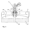
- the dispense head 5 is mounted onto the spear 3 in the beverage container 2.
- the dispense head 5 is not activated in Fig. 5 .
- the spear 3 comprises an extractor part 24 extending from the opening downwards to the bottom of the beverage container 2.
- an internal spring 25 is arranged which with a predetermined upward spring force closes off the beverage container via a closure 26 and related sealing elements.
- the beverage 27 in the beverage container 2 may be forced out of the container at the bottom via the extractor part 24 of the spear 3 when the pressurised gas, i.e. CO2, is supplied to the area 28 above the beverage 27.
- the pressurised gas i.e. CO2
- Fig. 6 shows the dispense head 5 of Fig. 5 , mounted on the spear 3, however, the beverage container 2 is not shown in this figure.
- the piston 14 comprises a turnable upper piston part 29, an upper piston part 30, an internal lower piston part 31, and a lower piston 32.
- the space 16 is in this embodiment arranged between the upper piston part 30 and the internal lower piston part 31, and openings 17 provide access and thereby fluid communication to the space 16.
- the space 16 is in this embodiment an annulus.
- the positioning means 20 is arranged between the turnable upper piston part 29 and the upper piston part 30, and above the first sealing 18.
- the positioning means 20 is in this embodiment an internal spring having a predetermined spring force, however, in other embodiments, the positioning means may also be a resilient element made of some kind of elastic material.
- a sealing device 33 for instance an elastic O-ring, may be arranged between the turnable upper piston part 29 and the upper piston part 30 to avoid leakage out of the dispense head 5 and to ensure that no dirt etc. enters the dispense head 5 unintendedly.
- Several other sealing devices may be arranged within the dispense head 5 to ensure that no unintended leakage occurs.
- the piston 14 may have an axially extending bore adapted for a beverage to be led through the dispense head 5 during dispensing.
- Fig. 7 the handle 9 has been moved downwards, thereby performing an axial displacement of the piston 14, which is also indicated by the lower piston 32 being displaced downwards and displacing the gasket around the closure 26 of the spear 3.
- the positioning means 20 secures that the space 16 is sealed off at this stage. In other embodiments it may be the closure which is displaced.
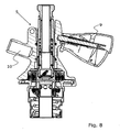
- Fig. 8 the handle 9 is in its lower position, whereby the dispense head 5 is activated and the gas inlet 10 is in fluid communication with the interior of the beverage container (not shown).
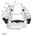
- FIG. 9 an enlarged cross-sectional view shows how the piston 14 has been forced slightly upwards so that the second sealing 19 is no longer placed opposite the projection 22. This creates a passage 35 through which the pressurised gas, i.e. CO2, may flow, continuing further down into the beverage container 2 via a gas channel.
- the pressurised gas i.e. CO2
- the internal spring 25 of the spear 3 has more power, i.e. spring force, than the inherent spring force of the positioning means 20, meaning that when the dispense head 5 is in a mounted and activated state, the piston will be pressed slightly upwards by the internal spring 25, or the internal spring of the spear 3 will stop the piston from displacing it further downwards during activation ensuring that the gas inlet 10 is in fluid communication with the beverage container 2.
- Fig. 10 another dispense head 51 is shown in a cross-sectional view.
- the handle 9 is in a lower position in Fig. 10 , whereby the dispense head 51 is activated.
- the dispense head 51 comprises a housing 13 and a piston 14, which is arranged axially displaceable within the housing 13.
- the piston 14 is connected to the handle 9 so that, upon activation of the handle 9, the piston 14 will be displaced axially towards the spear (not shown), whereby a top part of the spear (not shown) will be forced downwards, causing it to open the beverage container (not shown). From Fig. 10 , it is easily deduced that the lower part 15 of the piston 14 is displaced downwards in relation to the housing 13.
- the gas inlet 10 is arranged in the housing 13 and is in fluid communication with a channel 52.
- the channel 52 is arranged in the wall of the piston 14 and extends axially within the wall of the piston 14 between two radially arranged bores 53, 54.
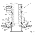
- Fig. 11 an enlarged cross-sectional view of the dispense head 51 of Fig. 10 is shown.
- the dispense head 51 is in this figure activated and gas may flow from the gas inlet 10 via the bore 53, the channel 52, the bore 54 and the opening 55 into the beverage container (not shown).
- the dispense head 51 also comprises a spring-loaded sleeve 56, which is arranged around the piston 14.
- the sleeve 56 is axially moveable in relation to the piston 14 and is arranged so that it may slide opposite the opening of the bore 54.
- the sleeve 56 may thereby open or close for the gas flow in the bore 54, and thereby avoiding unintended gas leakage.
- a helically spring 57 forces the sleeve 56 downwards.
- the sleeve abuts the main gasket 58, which forces the sleeve 56 upwards when the dispense head 51 is mounted and activated on the beverage container (not shown) in the same manner as described above.
- Fig. 12 shows a cross-sectional view of the dispense head 51 of Fig. 10 , wherein the dispense head 51 has been activated, i.e. the handle 9 is in its lowest position in a dismounted stage.
- the unintended gas leakage which may occur during activation of the handle 9 in circumstances where the dispense head is not mounted on a beverage container, is avoided.
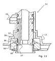
- Fig. 13 an enlarged cross-sectional view of the dispense head 51 of Fig. 12 is shown.
- the sleeve 56 is forced downwards by means of the spring 57 into its lowest position, wherein it closes off the opening of the bore 54 so that no gas may leak unintentionally.
- the main gasket 58 is also forced downwards by the activation of the handle (in Fig. 13 it is projecting below the housing 13 of the dispense head 51), and thereby it does not force the sleeve 56 upwards.
- the spring force of the spring 57 is then sufficient for forcing the sleeve 56 down in the position wherein it closes off the bore 54.
- a sealing 59 e.g. an o-ring, may be arranged between the sleeve 56 and the piston 14 for avoiding unintended gas leak.
- An additional sealing 60 may as well be arranged just below the opening of the bore 54 for sealing between the sleeve 56 and the bore 54, when the sleeve 56 is in its lowest position.
- FIG. 14 a cross-sectional view of the dispense head 51 of Fig. 10 is shown in an inactive and dismounted stage, where the handle 9 is not activated.
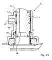
- FIG. 15 shows an enlarged cross-sectional view of the dispense head 51 of Fig. 14 , wherein the piston 14 is in its uppermost position.
- the piston 14 comprises an upper sealing and a lower sealing 62 arranged with a mutual distance between them.
- the sealings 61, 62 are arranged in their own recesses in the exterior wall of the piston 14 and may preferably be O-rings.
- the sealings 61, 62 are arranged so that they are positioned on each side of the gas inlet 10 when the piston are in the uppermost position, as shown in Figs. 14 and 15 .
- the sleeve 56 also closes off the bore 54 in this position, thereby providing an additional security of unintended gas leakage.
- Fig. 16 yet another dispense head 71 is shown in a cross-sectional view.
- the handle 9 is in Fig. 16 in a lower position, whereby the dispense head 71 is activated.
- the dispense head 71 comprises a housing 13 and a piston 14, which is arranged axially displaceable within the housing 13.
- the piston 14 is connected to the handle 9 so that, upon activation of the handle 9, the piston 14 will be displaced axially towards the spear (not shown), whereby a top part of the spear (not shown) will be forced downwards, causing it to open the beverage container (not shown). From Fig. 16 , it is easily deduced that the lower part 15 of the piston 14 is displaced downwards in relation to the housing 13.
- the gas inlet 10 is arranged in the housing 13 and is in fluid communication with a channel 72 arranged in a sleeve 73.
- the sleeve 73 is arranged in an exterior recess in the piston 14 and extends axially along the piston 14.
- the gas channel 72 may be arranged within the wall of the sleeve or it may be an axial groove arranged at the inside of the sleeve 73.
- a helically spring 74 is arranged above sleeve 73 for forcing the sleeve 73 downwards.
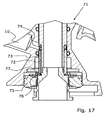
- Fig. 17 an enlarged cross-sectional view of the dispense head 71 of Fig. 16 is shown.
- the dispense head 71 is in this figure activated and gas may flow from the gas inlet 10 via the channel 72, the opening 76, passing the main gasket 75 into the beverage container (not shown).
- the dispense head 71 comprises a spring-loaded sleeve 73, which is arranged around the piston 14.
- the sleeve 73 is axially moveable in relation to the piston 14 and is arranged so that it may slide opposite the opening 76.
- the sleeve 73 may thereby open or close for the gas flow in the opening 76, and thereby avoiding unintended gas leakage.
- a helically spring 74 forces the sleeve 73 downwards.
- the sleeve 73 abuts the main gasket 75 via the radial flange 77, and in the same manner as described in connection with Figs. 10 to 15 , the main gasket forces the sleeve 73 upwards when the dispense head 71 is mounted and activated on the beverage container (not shown) in the same manner as described above.
- Fig. 18 shows a cross-sectional view of the dispense head 71 of Fig. 16 , wherein the dispense head 71 has been activated, i.e. the handle 9 is in its lowest position in a dismounted stage.
- the unintended gas leakage which may occur during activation of the handle 9 in circumstances where the dispense head is not mounted on a beverage container, is avoided.
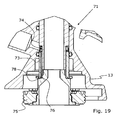
- Fig. 19 an enlarged cross-sectional view of the dispense head 71 of Fig. 18 is shown.
- the sleeve 73 is forced downwards by means of the spring 74 into its lowest position, wherein it closes off the opening 76 so that no gas may leak unintentionally.
- the main gasket 75 is also forced downwards by the activation of the handle (in Fig. 19 it is projecting below the housing 13 of the dispense head 71), and thereby it does not force the sleeve 73 upwards.
- the spring force of the spring 74 is then sufficient for forcing the sleeve 73 down in the position wherein it closes off the opening 76.
- a sealing 78 e.g. an O-ring, may be arranged just below the opening 76 for sealing between the sleeve 73 and the opening 76, when the sleeve 73 is in its lowest position (as shown in Fig. 19 ).
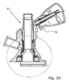
- FIG. 20 a cross-sectional view of the dispense head 71 of Fig. 16 in an inactive and dismounted stage, where the handle 9 is not activated, is shown.
- Fig. 21 shows an enlarged cross-sectional view of the dispense head 71 of Fig. 20 , wherein the piston 14 is in its uppermost position.
- the housing 13 comprises an upper sealing 79 and a lower sealing 80 arranged with a mutual distance between them.
- the sealings 79, 80 are arranged in their own recesses in the interior wall of the housing 13 and may preferably be o-rings.
- the sealings 79, 80 are arranged so that they are positioned on each side of the gas inlet 10.
- the sleeve 73 is moved upwards so that it is placed opposite the gas inlet 10. Thereby, the sleeve 73 and the two sealings 79, 80 avoid unintended gas leak from the gas inlet 10. Furthermore, the sleeve 73 also closes off the opening 76 in this position, thereby providing an additional security of unintended gas leakage.
- the sleeve 73 may be made of metal or plastic material, or a combination thereof.
Landscapes
- Devices For Dispensing Beverages (AREA)
Claims (10)
- Abgabekopf (5), der ausgelegt ist, um an einen Getränkebehälter (2) gekoppelt zu werden, oberhalb eines Stechrohrs (spear 3), das in dem Getränkebehälter (2) angeordnet ist, in einem Abgabesystem (1), wobei der Abgabekopf (5) umfasst:ein Gehäuse (13), eine Handhabe (9), einen Kolben (14), der axial versetzbar innerhalb des Gehäuses (13) angeordnet ist, wobei der Kolben (14) mit der Handhabe (9) verbunden ist, so dass bei Aktivierung der Handhabe (9) der Kolben (14) axial zu dem Stechrohr (3) versetzt wird, wobei dadurch ein oberer Teil des Stechrohrs nach unten gezwungen wird, was es dazu bringt, den Getränkebehälter (2) zu öffnen, einen Gaseinlass (10), der in dem Gehäuse (13) angeordnet ist, der ausgelegt ist, um in einer Fluidverbindung mit einem Raum (16) zu stehen, der sich entlang des Kolbens (14) erstreckt, wobei der Raum (16) wenigstens an einem oberen Ende mit einer ersten Dichtung (18) und an einem unteren Ende mit einer zweiten Dichtung (19) abgedichtet ist,dadurch gekennzeichnet, dass der Abgabekopf (5) weiter umfasst:einen Vorsprung (22) entweder an dem Gehäuse (13) oder innerhalb des Kolbens (14),ein Positioniermittel (20), das in Verbindung mit dem Kolben (14) angeordnet ist, was es der ersten Dichtung (18) und der zweiten Dichtung (19) ermöglicht, in Abdichtpositionen angeordnet zu werden, so dass diese radial gegen den Vorsprung (22) abdichten, wobei dadurch bei einer unbeabsichtigten Aktivierung der Handhabe (9), wenn der Abgabekopf (5) vom Getränkebehälter (2) getrennt ist, kein CO2 in die Umgebung entweichen wird.
- Abgabekopf (5) gemäß Anspruch 1, bei dem das Positioniermittel (20) als ein nachgiebiges Element ausgebildet ist, wie zum Beispiel eine Feder, oder aus einem elastischen Material hergestellt ist.
- Abgabekopf (5) gemäß Anspruch 2, bei dem das Positioniermittel (20) eine Federkraft aufweist.
- Abgabekopf (5) gemäß Anspruch 1, bei dem das Positioniermittel (20) oberhalb der ersten Dichtung (18) angeordnet ist.
- Abgabekopf (5) gemäß Anspruch 1, bei dem der Raum (16) als ein Ringraum ausgebildet ist, der sich entlang des Kolbens (14) erstreckt.
- Abgabekopf (5) gemäß Anspruch 1, bei dem der Raum (16) zwischen einer Außenseite des Kolbens (14) und dem Gehäuse (13) angeordnet ist oder innerhalb des Kolbens (14) angeordnet ist.
- Abgabekopf (5) gemäß Anspruch 1, bei dem die Dichtungen (18, 19) als O-Ringe ausgebildet sind.
- Abgabekopf (5) gemäß Anspruch 1, bei dem der Kolben (14) eine axiale Bohrung aufweist, die ausgelegt ist, um ein Getränk durch den Abgabekopf während der Abgabe zu leiten.
- Abgabesystem (1) zur Abgabe von Getränken, wobei das System einen Getränkebehälter (2) mit einem Stechrohr (3) umfasst, das in einer Öffnung des Getränkebehälters (2) angeordnet ist, das ausgelegt ist, um als Ventil zu fungieren, wobei das Stechrohr (3) aufweist eine innere Feder (25) mit einer Federkraft, die es der Öffnung des Getränkebehälters ermöglicht, geschlossen gehalten zu werden, eine Gaszufuhr (4), ein Abgabehahn (6), und einen Abgabekopf (5) gemäß einem der Ansprüche 1 bis 8.
- Abgabesystem (1) gemäß Anspruch 9, bei dem die Federkraft des Positioniermittels (20) geringer als die Federkraft der inneren Feder (25) ausgebildet ist.
Applications Claiming Priority (2)
| Application Number | Priority Date | Filing Date | Title |
|---|---|---|---|
| DKPA201070182 | 2010-04-29 | ||
| PCT/EP2011/056821 WO2011135066A1 (en) | 2010-04-29 | 2011-04-29 | Dispense head for a draft beverage dispensing system |
Publications (2)
| Publication Number | Publication Date |
|---|---|
| EP2563714A1 EP2563714A1 (de) | 2013-03-06 |
| EP2563714B1 true EP2563714B1 (de) | 2015-02-11 |
Family
ID=44064650
Family Applications (1)
| Application Number | Title | Priority Date | Filing Date |
|---|---|---|---|
| EP11716921.9A Not-in-force EP2563714B1 (de) | 2010-04-29 | 2011-04-29 | Zapfkopf für ein getränkeausgabesystem unter druck |
Country Status (2)
| Country | Link |
|---|---|
| EP (1) | EP2563714B1 (de) |
| WO (1) | WO2011135066A1 (de) |
Families Citing this family (4)
| Publication number | Priority date | Publication date | Assignee | Title |
|---|---|---|---|---|
| CN105036046B (zh) * | 2015-08-11 | 2018-05-18 | 塔罗斯控股有限公司 | 一种分配器手柄 |
| CN105110268B (zh) * | 2015-08-11 | 2017-06-06 | 塔罗斯控股有限公司 | 一种分配器 |
| CN105036044B (zh) * | 2015-08-11 | 2018-09-21 | 塔罗斯控股有限公司 | 一种分配器手柄 |
| CN105000523B (zh) * | 2015-08-11 | 2017-07-04 | 塔罗斯控股有限公司 | 一种分配器 |
Family Cites Families (2)
| Publication number | Priority date | Publication date | Assignee | Title |
|---|---|---|---|---|
| US4450853A (en) * | 1981-07-21 | 1984-05-29 | Robert Dessenoix | Assembly for drawing off a liquid by means of a gas under pressure |
| JP2010538926A (ja) * | 2007-09-20 | 2010-12-16 | マイクロ・マティック・エー/エス | 飲料容器に搭載された抽出装置と接続するためのディスペンサーヘッド |
-
2011
- 2011-04-29 EP EP11716921.9A patent/EP2563714B1/de not_active Not-in-force
- 2011-04-29 WO PCT/EP2011/056821 patent/WO2011135066A1/en not_active Ceased
Also Published As
| Publication number | Publication date |
|---|---|
| EP2563714A1 (de) | 2013-03-06 |
| WO2011135066A1 (en) | 2011-11-03 |
Similar Documents
| Publication | Publication Date | Title |
|---|---|---|
| EP2625133B1 (de) | Dispensierkopf für ein abgabesystem | |
| US20230303312A1 (en) | Beverage container having a pressure-relief device and a method of manufacturing a beverage container having a pressure-relief device | |
| CN101185043B (zh) | 用于可固定在容器盖下面的压力气体储罐的具有刺穿机构的减压和调压阀 | |
| EP3569921B1 (de) | Pneumatisches tellerventil für ein aufblassystem | |
| US3361152A (en) | Keg valve | |
| EP3527870B1 (de) | Druckabgabesystem | |
| US11402069B2 (en) | Valve assembly | |
| US20130299500A1 (en) | Commercial fueling system with vapor capture | |
| US20160137478A1 (en) | Overpressure valve of a spear tube valve | |
| EP2563714A1 (de) | Spenderkopf für ein system zur ausgabe von schankgetränken | |
| US4450853A (en) | Assembly for drawing off a liquid by means of a gas under pressure | |
| EP3145855B1 (de) | Getränkeausgabeanordnung mit flexiblem ventil | |
| AU2018220011A1 (en) | Spill-resistant vacuum breaker valve | |
| CN103836220A (zh) | 自密封滑阀 | |
| CN203823104U (zh) | 自密封滑阀 | |
| JP2010526263A (ja) | Co2圧縮ガス源と超過圧力保護手段とを有する容器 | |
| EP2540660B1 (de) | Getränkeausgabesystem | |
| US10829360B2 (en) | Dispense head with pressure equalising valve | |
| KR20050094642A (ko) | 자기 폐쇄 기능을 구비한 엘피지 용기용 밸브 | |
| US6659127B2 (en) | Relief valve | |
| EP2572761A2 (de) | Verbessertes Dosierventil für einen Feuerlöscher | |
| WO2020099287A1 (en) | Beer tap with foam control | |
| US20130015212A1 (en) | Dispensing unit for liquid containers | |
| US11835143B2 (en) | Filling valve | |
| CN116635654A (zh) | 带有集成截止阀的除气器 |
Legal Events
| Date | Code | Title | Description |
|---|---|---|---|
| PUAI | Public reference made under article 153(3) epc to a published international application that has entered the european phase |
Free format text: ORIGINAL CODE: 0009012 |
|
| 17P | Request for examination filed |
Effective date: 20121105 |
|
| AK | Designated contracting states |
Kind code of ref document: A1 Designated state(s): AL AT BE BG CH CY CZ DE DK EE ES FI FR GB GR HR HU IE IS IT LI LT LU LV MC MK MT NL NO PL PT RO RS SE SI SK SM TR |
|
| DAX | Request for extension of the european patent (deleted) | ||
| GRAP | Despatch of communication of intention to grant a patent |
Free format text: ORIGINAL CODE: EPIDOSNIGR1 |
|
| INTG | Intention to grant announced |
Effective date: 20140910 |
|
| GRAS | Grant fee paid |
Free format text: ORIGINAL CODE: EPIDOSNIGR3 |
|
| GRAP | Despatch of communication of intention to grant a patent |
Free format text: ORIGINAL CODE: EPIDOSNIGR1 |
|
| GRAA | (expected) grant |
Free format text: ORIGINAL CODE: 0009210 |
|
| INTG | Intention to grant announced |
Effective date: 20141222 |
|
| AK | Designated contracting states |
Kind code of ref document: B1 Designated state(s): AL AT BE BG CH CY CZ DE DK EE ES FI FR GB GR HR HU IE IS IT LI LT LU LV MC MK MT NL NO PL PT RO RS SE SI SK SM TR |
|
| REG | Reference to a national code |
Ref country code: GB Ref legal event code: FG4D |
|
| REG | Reference to a national code |
Ref country code: CH Ref legal event code: EP |
|
| REG | Reference to a national code |
Ref country code: IE Ref legal event code: FG4D |
|
| REG | Reference to a national code |
Ref country code: AT Ref legal event code: REF Ref document number: 709854 Country of ref document: AT Kind code of ref document: T Effective date: 20150315 |
|
| REG | Reference to a national code |
Ref country code: DE Ref legal event code: R096 Ref document number: 602011013630 Country of ref document: DE Effective date: 20150319 |
|
| REG | Reference to a national code |
Ref country code: NL Ref legal event code: VDEP Effective date: 20150211 |
|
| REG | Reference to a national code |
Ref country code: AT Ref legal event code: MK05 Ref document number: 709854 Country of ref document: AT Kind code of ref document: T Effective date: 20150211 |
|
| REG | Reference to a national code |
Ref country code: LT Ref legal event code: MG4D |
|
| PG25 | Lapsed in a contracting state [announced via postgrant information from national office to epo] |
Ref country code: ES Free format text: LAPSE BECAUSE OF FAILURE TO SUBMIT A TRANSLATION OF THE DESCRIPTION OR TO PAY THE FEE WITHIN THE PRESCRIBED TIME-LIMIT Effective date: 20150211 Ref country code: SE Free format text: LAPSE BECAUSE OF FAILURE TO SUBMIT A TRANSLATION OF THE DESCRIPTION OR TO PAY THE FEE WITHIN THE PRESCRIBED TIME-LIMIT Effective date: 20150211 Ref country code: HR Free format text: LAPSE BECAUSE OF FAILURE TO SUBMIT A TRANSLATION OF THE DESCRIPTION OR TO PAY THE FEE WITHIN THE PRESCRIBED TIME-LIMIT Effective date: 20150211 Ref country code: FI Free format text: LAPSE BECAUSE OF FAILURE TO SUBMIT A TRANSLATION OF THE DESCRIPTION OR TO PAY THE FEE WITHIN THE PRESCRIBED TIME-LIMIT Effective date: 20150211 Ref country code: NO Free format text: LAPSE BECAUSE OF FAILURE TO SUBMIT A TRANSLATION OF THE DESCRIPTION OR TO PAY THE FEE WITHIN THE PRESCRIBED TIME-LIMIT Effective date: 20150511 Ref country code: LT Free format text: LAPSE BECAUSE OF FAILURE TO SUBMIT A TRANSLATION OF THE DESCRIPTION OR TO PAY THE FEE WITHIN THE PRESCRIBED TIME-LIMIT Effective date: 20150211 |
|
| PG25 | Lapsed in a contracting state [announced via postgrant information from national office to epo] |
Ref country code: RS Free format text: LAPSE BECAUSE OF FAILURE TO SUBMIT A TRANSLATION OF THE DESCRIPTION OR TO PAY THE FEE WITHIN THE PRESCRIBED TIME-LIMIT Effective date: 20150211 Ref country code: LV Free format text: LAPSE BECAUSE OF FAILURE TO SUBMIT A TRANSLATION OF THE DESCRIPTION OR TO PAY THE FEE WITHIN THE PRESCRIBED TIME-LIMIT Effective date: 20150211 Ref country code: GR Free format text: LAPSE BECAUSE OF FAILURE TO SUBMIT A TRANSLATION OF THE DESCRIPTION OR TO PAY THE FEE WITHIN THE PRESCRIBED TIME-LIMIT Effective date: 20150512 Ref country code: AT Free format text: LAPSE BECAUSE OF FAILURE TO SUBMIT A TRANSLATION OF THE DESCRIPTION OR TO PAY THE FEE WITHIN THE PRESCRIBED TIME-LIMIT Effective date: 20150211 Ref country code: IS Free format text: LAPSE BECAUSE OF FAILURE TO SUBMIT A TRANSLATION OF THE DESCRIPTION OR TO PAY THE FEE WITHIN THE PRESCRIBED TIME-LIMIT Effective date: 20150611 Ref country code: NL Free format text: LAPSE BECAUSE OF FAILURE TO SUBMIT A TRANSLATION OF THE DESCRIPTION OR TO PAY THE FEE WITHIN THE PRESCRIBED TIME-LIMIT Effective date: 20150211 |
|
| PG25 | Lapsed in a contracting state [announced via postgrant information from national office to epo] |
Ref country code: EE Free format text: LAPSE BECAUSE OF FAILURE TO SUBMIT A TRANSLATION OF THE DESCRIPTION OR TO PAY THE FEE WITHIN THE PRESCRIBED TIME-LIMIT Effective date: 20150211 Ref country code: CZ Free format text: LAPSE BECAUSE OF FAILURE TO SUBMIT A TRANSLATION OF THE DESCRIPTION OR TO PAY THE FEE WITHIN THE PRESCRIBED TIME-LIMIT Effective date: 20150211 Ref country code: RO Free format text: LAPSE BECAUSE OF FAILURE TO SUBMIT A TRANSLATION OF THE DESCRIPTION OR TO PAY THE FEE WITHIN THE PRESCRIBED TIME-LIMIT Effective date: 20150211 Ref country code: SK Free format text: LAPSE BECAUSE OF FAILURE TO SUBMIT A TRANSLATION OF THE DESCRIPTION OR TO PAY THE FEE WITHIN THE PRESCRIBED TIME-LIMIT Effective date: 20150211 Ref country code: DK Free format text: LAPSE BECAUSE OF FAILURE TO SUBMIT A TRANSLATION OF THE DESCRIPTION OR TO PAY THE FEE WITHIN THE PRESCRIBED TIME-LIMIT Effective date: 20150211 |
|
| REG | Reference to a national code |
Ref country code: DE Ref legal event code: R097 Ref document number: 602011013630 Country of ref document: DE |
|
| PG25 | Lapsed in a contracting state [announced via postgrant information from national office to epo] |
Ref country code: PL Free format text: LAPSE BECAUSE OF FAILURE TO SUBMIT A TRANSLATION OF THE DESCRIPTION OR TO PAY THE FEE WITHIN THE PRESCRIBED TIME-LIMIT Effective date: 20150211 Ref country code: LU Free format text: LAPSE BECAUSE OF FAILURE TO SUBMIT A TRANSLATION OF THE DESCRIPTION OR TO PAY THE FEE WITHIN THE PRESCRIBED TIME-LIMIT Effective date: 20150429 Ref country code: MC Free format text: LAPSE BECAUSE OF FAILURE TO SUBMIT A TRANSLATION OF THE DESCRIPTION OR TO PAY THE FEE WITHIN THE PRESCRIBED TIME-LIMIT Effective date: 20150211 |
|
| REG | Reference to a national code |
Ref country code: CH Ref legal event code: PL |
|
| PLBE | No opposition filed within time limit |
Free format text: ORIGINAL CODE: 0009261 |
|
| STAA | Information on the status of an ep patent application or granted ep patent |
Free format text: STATUS: NO OPPOSITION FILED WITHIN TIME LIMIT |
|
| PG25 | Lapsed in a contracting state [announced via postgrant information from national office to epo] |
Ref country code: IT Free format text: LAPSE BECAUSE OF FAILURE TO SUBMIT A TRANSLATION OF THE DESCRIPTION OR TO PAY THE FEE WITHIN THE PRESCRIBED TIME-LIMIT Effective date: 20150211 |
|
| 26N | No opposition filed |
Effective date: 20151112 |
|
| GBPC | Gb: european patent ceased through non-payment of renewal fee |
Effective date: 20150511 |
|
| REG | Reference to a national code |
Ref country code: IE Ref legal event code: MM4A |
|
| PG25 | Lapsed in a contracting state [announced via postgrant information from national office to epo] |
Ref country code: CH Free format text: LAPSE BECAUSE OF NON-PAYMENT OF DUE FEES Effective date: 20150430 Ref country code: LI Free format text: LAPSE BECAUSE OF NON-PAYMENT OF DUE FEES Effective date: 20150430 |
|
| REG | Reference to a national code |
Ref country code: FR Ref legal event code: ST Effective date: 20151231 |
|
| PG25 | Lapsed in a contracting state [announced via postgrant information from national office to epo] |
Ref country code: SI Free format text: LAPSE BECAUSE OF FAILURE TO SUBMIT A TRANSLATION OF THE DESCRIPTION OR TO PAY THE FEE WITHIN THE PRESCRIBED TIME-LIMIT Effective date: 20150211 Ref country code: FR Free format text: LAPSE BECAUSE OF NON-PAYMENT OF DUE FEES Effective date: 20150430 |
|
| PG25 | Lapsed in a contracting state [announced via postgrant information from national office to epo] |
Ref country code: GB Free format text: LAPSE BECAUSE OF NON-PAYMENT OF DUE FEES Effective date: 20150511 Ref country code: IE Free format text: LAPSE BECAUSE OF NON-PAYMENT OF DUE FEES Effective date: 20150429 |
|
| PG25 | Lapsed in a contracting state [announced via postgrant information from national office to epo] |
Ref country code: BE Free format text: LAPSE BECAUSE OF FAILURE TO SUBMIT A TRANSLATION OF THE DESCRIPTION OR TO PAY THE FEE WITHIN THE PRESCRIBED TIME-LIMIT Effective date: 20150211 |
|
| PG25 | Lapsed in a contracting state [announced via postgrant information from national office to epo] |
Ref country code: MT Free format text: LAPSE BECAUSE OF FAILURE TO SUBMIT A TRANSLATION OF THE DESCRIPTION OR TO PAY THE FEE WITHIN THE PRESCRIBED TIME-LIMIT Effective date: 20150211 |
|
| PG25 | Lapsed in a contracting state [announced via postgrant information from national office to epo] |
Ref country code: HU Free format text: LAPSE BECAUSE OF FAILURE TO SUBMIT A TRANSLATION OF THE DESCRIPTION OR TO PAY THE FEE WITHIN THE PRESCRIBED TIME-LIMIT; INVALID AB INITIO Effective date: 20110429 Ref country code: SM Free format text: LAPSE BECAUSE OF FAILURE TO SUBMIT A TRANSLATION OF THE DESCRIPTION OR TO PAY THE FEE WITHIN THE PRESCRIBED TIME-LIMIT Effective date: 20150211 Ref country code: BG Free format text: LAPSE BECAUSE OF FAILURE TO SUBMIT A TRANSLATION OF THE DESCRIPTION OR TO PAY THE FEE WITHIN THE PRESCRIBED TIME-LIMIT Effective date: 20150211 |
|
| PG25 | Lapsed in a contracting state [announced via postgrant information from national office to epo] |
Ref country code: CY Free format text: LAPSE BECAUSE OF FAILURE TO SUBMIT A TRANSLATION OF THE DESCRIPTION OR TO PAY THE FEE WITHIN THE PRESCRIBED TIME-LIMIT Effective date: 20150211 |
|
| PG25 | Lapsed in a contracting state [announced via postgrant information from national office to epo] |
Ref country code: PT Free format text: LAPSE BECAUSE OF FAILURE TO SUBMIT A TRANSLATION OF THE DESCRIPTION OR TO PAY THE FEE WITHIN THE PRESCRIBED TIME-LIMIT Effective date: 20150611 |
|
| PG25 | Lapsed in a contracting state [announced via postgrant information from national office to epo] |
Ref country code: TR Free format text: LAPSE BECAUSE OF FAILURE TO SUBMIT A TRANSLATION OF THE DESCRIPTION OR TO PAY THE FEE WITHIN THE PRESCRIBED TIME-LIMIT Effective date: 20150211 |
|
| PG25 | Lapsed in a contracting state [announced via postgrant information from national office to epo] |
Ref country code: MK Free format text: LAPSE BECAUSE OF FAILURE TO SUBMIT A TRANSLATION OF THE DESCRIPTION OR TO PAY THE FEE WITHIN THE PRESCRIBED TIME-LIMIT Effective date: 20150211 |
|
| PG25 | Lapsed in a contracting state [announced via postgrant information from national office to epo] |
Ref country code: AL Free format text: LAPSE BECAUSE OF FAILURE TO SUBMIT A TRANSLATION OF THE DESCRIPTION OR TO PAY THE FEE WITHIN THE PRESCRIBED TIME-LIMIT Effective date: 20150211 |
|
| PGFP | Annual fee paid to national office [announced via postgrant information from national office to epo] |
Ref country code: DE Payment date: 20200420 Year of fee payment: 10 |
|
| REG | Reference to a national code |
Ref country code: DE Ref legal event code: R119 Ref document number: 602011013630 Country of ref document: DE |
|
| PG25 | Lapsed in a contracting state [announced via postgrant information from national office to epo] |
Ref country code: DE Free format text: LAPSE BECAUSE OF NON-PAYMENT OF DUE FEES Effective date: 20211103 |