EP2564084B1 - Système de palier à roulement à capteur d'angle - Google Patents
Système de palier à roulement à capteur d'angle Download PDFInfo
- Publication number
- EP2564084B1 EP2564084B1 EP11719503.2A EP11719503A EP2564084B1 EP 2564084 B1 EP2564084 B1 EP 2564084B1 EP 11719503 A EP11719503 A EP 11719503A EP 2564084 B1 EP2564084 B1 EP 2564084B1
- Authority
- EP
- European Patent Office
- Prior art keywords
- ring
- roller bearing
- coils
- pot core
- sensor
- Prior art date
- Legal status (The legal status is an assumption and is not a legal conclusion. Google has not performed a legal analysis and makes no representation as to the accuracy of the status listed.)
- Not-in-force
Links
Images



Classifications
-
- G—PHYSICS
- G01—MEASURING; TESTING
- G01B—MEASURING LENGTH, THICKNESS OR SIMILAR LINEAR DIMENSIONS; MEASURING ANGLES; MEASURING AREAS; MEASURING IRREGULARITIES OF SURFACES OR CONTOURS
- G01B7/00—Measuring arrangements characterised by the use of electric or magnetic techniques
- G01B7/30—Measuring arrangements characterised by the use of electric or magnetic techniques for measuring angles or tapers; for testing the alignment of axes
-
- F—MECHANICAL ENGINEERING; LIGHTING; HEATING; WEAPONS; BLASTING
- F16—ENGINEERING ELEMENTS AND UNITS; GENERAL MEASURES FOR PRODUCING AND MAINTAINING EFFECTIVE FUNCTIONING OF MACHINES OR INSTALLATIONS; THERMAL INSULATION IN GENERAL
- F16C—SHAFTS; FLEXIBLE SHAFTS; ELEMENTS OR CRANKSHAFT MECHANISMS; ROTARY BODIES OTHER THAN GEARING ELEMENTS; BEARINGS
- F16C41/00—Other accessories, e.g. devices integrated in the bearing not relating to the bearing function as such
-
- F—MECHANICAL ENGINEERING; LIGHTING; HEATING; WEAPONS; BLASTING
- F16—ENGINEERING ELEMENTS AND UNITS; GENERAL MEASURES FOR PRODUCING AND MAINTAINING EFFECTIVE FUNCTIONING OF MACHINES OR INSTALLATIONS; THERMAL INSULATION IN GENERAL
- F16C—SHAFTS; FLEXIBLE SHAFTS; ELEMENTS OR CRANKSHAFT MECHANISMS; ROTARY BODIES OTHER THAN GEARING ELEMENTS; BEARINGS
- F16C19/00—Bearings with rolling contact, for exclusively rotary movement
- F16C19/02—Bearings with rolling contact, for exclusively rotary movement with bearing balls essentially of the same size in one or more circular rows
- F16C19/04—Bearings with rolling contact, for exclusively rotary movement with bearing balls essentially of the same size in one or more circular rows for radial load mainly
- F16C19/06—Bearings with rolling contact, for exclusively rotary movement with bearing balls essentially of the same size in one or more circular rows for radial load mainly with a single row or balls
-
- G—PHYSICS
- G01—MEASURING; TESTING
- G01M—TESTING STATIC OR DYNAMIC BALANCE OF MACHINES OR STRUCTURES; TESTING OF STRUCTURES OR APPARATUS, NOT OTHERWISE PROVIDED FOR
- G01M1/00—Testing static or dynamic balance of machines or structures
-
- G—PHYSICS
- G06—COMPUTING OR CALCULATING; COUNTING
- G06F—ELECTRIC DIGITAL DATA PROCESSING
- G06F1/00—Details not covered by groups G06F3/00 - G06F13/00 and G06F21/00
-
- G—PHYSICS
- G06—COMPUTING OR CALCULATING; COUNTING
- G06F—ELECTRIC DIGITAL DATA PROCESSING
- G06F2200/00—Indexing scheme relating to G06F1/04 - G06F1/32
Definitions
- the invention relates to a rolling bearing assembly with an angle sensor according to the preamble of claim 1 and a method for mounting such a rolling bearing assembly with an angle sensor.
- a generic arrangement which comprises a rolling bearing and a designated as resolver, designed as an absolute value encoder angle sensor is, for example, from US 2006/0087315 A1 known.
- the angle sensor has a stator connected to the outer ring of the rolling bearing, as well as a cooperating with the stator rotor, which is formed as eccentric ring and formed by the inner ring of the rolling bearing.
- micro-transmitting and micro-receiving coils of the sensor are arranged on a carrier, namely a substrate of a printed circuit.
- carrier Processing circuit containing an oscillator and phase demodulators.
- the invention has for its object to provide a particular arrangement for smaller rolling bearing types, for example deep groove ball bearings with less than 40 mm outer diameter, suitable arrangement of storage and angle sensor, which is characterized both by a small footprint and by a very simple mounting option. Furthermore, it is an object of the invention to provide a manufacturing technology advantageous angle sensor, which is usable without assembly with a rolling bearing.
- the material measure which serves to close the magnetic circuit, is preferably arranged on the rotating ring, in the case of a bearing arrangement with a rotating shaft, ie on the inner ring. In the case of a stationary inner ring and rotating outer ring, the material measure is accordingly connected to the outer ring.
- At least one coil, preferably each coil, of the sensor ring is designed as a printed circuit.
- different receiving coils namely sinusoidal and cosine coils formed by a plurality of turns, are provided, wherein the turns of the sine or cosine coils are arranged alternately on superimposed layers of a printed circuit designed as a multi-layer printed circuit board.
- two turns of a sine coil or two turns of a cosine coil are preferably arranged on each layer.
- the rolling bearing is designed as a radial bearing, for example deep groove ball bearings, wherein the sensor ring with the outer ring as the first bearing ring and the material measure in the form of an eccentric to the bearing axis ring, preferably doppelelexzentrischen ring with the inner ring as the second Bearing ring is connected.
- Deviating from an eccentric or doppelelexzentrischen design of acting as a measuring scale ring embodiments are also feasible, in which the ring is arranged centrally to the axis of rotation and - in the axial direction - exclusively circular contours, but has a varying thickness along the circumference. In both embodiments, an angle-dependent air gap between the scale and shell core is given.
- the holding structure preferably comprises a holding element designed as a plastic injection-molded part, which is fastened directly to the outer ring and is surrounded radially by a metal support ring which contacts an end face of the outer ring.
- a holding element designed as a plastic injection-molded part, which is fastened directly to the outer ring and is surrounded radially by a metal support ring which contacts an end face of the outer ring.
- the support ring projects beyond the shell core in the axial direction, the support ring according to a first variant having in its shell projecting region a fastening lug which bends radially inward from its circumference for holding a cable connected to the sensor ring.
- the support ring has only a recess on its circumference, which is provided for the passage of a cable.
- This cable is preferably formed in this area as a flexible circuit board and secured to a strip-shaped holder, which is integrally formed with the shell core and merges into the orthogonal to the axis of rotation of the angle sensor and the entire rolling bearing assembly U-base of the shell core.
- an iron powder core In the shell core is optionally provided an iron powder core. This combines good magnetic properties advantageously with low electrical conductivity and low eddy currents.
- the material measure can be formed by a component having iron powder.
- a particularly good space utilization is given in a preferred embodiment in which the radially outer U-legs of the shell core is arranged radially outside the inner ring and the radially inner U-legs of the shell core radially within the raceway formed by the inner race of the rolling elements.
- the radius of the circle described by the outer U-leg, symmetrical to the axis of rotation is preferably smaller than the inner radius of the outer ring.
- the advantage of the invention is in particular that with the U-shaped shell core, in which there is a single transmitting coil - without iron core - is a very space-saving, among other suitable for the commutation of electric motors Resolver is provided, which is suitable for small rolling bearing types, such as deep groove ball bearings with 15 mm inner diameter and 35 mm outer diameter, temperatures up to 150 ° C, as well as strong shock and vibration loads.
- the inner U-leg of the shell core has an inner diameter which is slightly larger than the inner diameter of the inner ring.
- an inner support sleeve is pushed onto the shaft surrounded by the inner ring of the rolling bearing in the region of the radially inwardly disposed U-leg of the shell core, abutting against the end face of the inner ring.
- rolling bearing assembly is composed of a rolling bearing 2, namely a deep groove ball bearing, and an angle sensor 3.
- a rolling bearing 2 As components of the rolling bearing 2 are in Fig. 3 an inner ring 4, an outer ring 5, rolling elements 6, namely balls, a leading cage this 7, and a sealing disc 8 at a first end face of the rolling bearing 2 to recognize.
- the coupled with the rolling bearing 2 angle sensor 3 has a sensor ring 9 which is rotatably connected to the outer ring 5, and a material measure 10, which is formed as relative to the axis of rotation R of the rolling bearing 2 eccentric metal ring and rotatably connected to the inner ring 4.
- the sensor ring 9 As a metallic component, the sensor ring 9 an annular, concentric with the axis of rotation R of the rolling bearing 2, in cross-section U-shaped shell core 11.
- the U-profile of the shell core 11 is open to the sealing disc 8 facing away from the end of the rolling bearing 2, wherein an outer U-leg 12 is located on the surface of an imaginary cylinder whose axis of symmetry with the axis of rotation R is identical, and whose radius is greater than that Outer radius of the inner ring 4, but smaller than the inner radius of the outer ring 5 is.
- a holding element 17 is provided made of plastic, which is fixed in a circumferential groove 18 in the outer ring 5.
- a support ring 19 made of sheet metal, which abuts against the end face of the outer ring 5 and serves as an assembly aid, and a mechanical protection of the angle sensor. 3 represents.
- annular space 20 Between the inner circumferential surface of the support ring 19 and the holding element 17th is an annular space 20, that is, an annular gap, formed in the finished mounted rolling bearing assembly 1 (FIG. Fig. 1-3 ) is filled with components of the sensor ring 9 described in more detail below.
- the sensor ring 9 has a transmitting coil 21, which is arranged concentrically to the axis of rotation R, that is substantially in a plane parallel to the end face of the rolling bearing 2, completely within the U-profile of the shell core 11.
- the average diameter of the transmitting coil 21 is about as large as the diameter of the raceway 15 on the inner ring 4.
- the transmitting coil 21 is designed as a 12-layer multilayer printed circuit board. With the transmission coil 21, which is acted upon by a signal having a frequency of, for example, 4000 Hz, different reception coils 22, 23 cooperate with a coupling in the manner of a transformer.
- Each of the receiving coils 22,23 is partially disposed within the U-profile of the shell core 11 and partially outside this U-profile.
- the corresponding printed circuit board 24, on which the receiving coils 22, 23 designed analogously to the transmitting coil 21 are arranged as a printed circuit, has a plurality of segment-like openings 25 describing individual sections of an annular space.
- 25 portions of the retaining element 17 protrude into these openings; on the other hand remain slotted 26 directly on the support member 17 plugged circuit board slots 26 within the holding element 17 through which portions of the outer U-leg 12 of the shell core 11 are inserted in the fully assembled state.
- These sections of the outer U-leg 12 protrude in the axial direction - with respect to the axis of rotation R - further to the rolling elements 6, even beyond the angle sensor 3 facing end face of the rolling bearing 2, as the inner U-leg 14th
- the material measure 10 Radial within the rolling bearing 2 facing the end of the outer U-leg 12 is the material measure 10, wherein between the said components 12,10 of the magnetic circuit used for measuring the angle, a variable, angle-dependent gap is formed.
- the gap width dependent magnetic resistance are as receiving coils 22,23 different sine coils 22 and in FIG. 4 merely indicated cosine coils 23 are provided.
- the circuit board 24 there are located on a single layer 27, that is, on a single layer, the circuit board 24 either two turns 28 of the sine-coil 22 or two windings 29 of the cosine coils 23, wherein the windings 28 of the sine-coil 22 with respect to the windings 29th the cosine coils 23 are rotated by 90 °.
- the windings 28 of the sine-wave coils 22 and the windings 29 of the cosine-coils 23 are arranged alternately on different layers 27, that is to say on a layer 27 with turns 28 of the sine-wave coils 22 is another layer 27 with turns 29 of the cosine coils. Coils 23 placed, then again a sinusoidal coil 22 belonging layer 27 and so on. Overall, the circuit board 24 is composed of 11 layers 27 of the sine coils 22 and the cosine coils 23 together.
- the electrical signal supplied by the angle sensor 3 is transmitted via a cable 30 connected to the coils 21, 22, 23 to a control and evaluation unit 31 spatially separated from the angle sensor 3. Due to the spatial separation between the angle sensor 3 and any electronic components, the rolling bearing assembly 1 including angle sensor 3 is particularly suitable for high operating temperatures of, for example, up to 155 ° C.
- the cable 30 is held on a fastening tab 31, which kinks inwardly from an area of the support ring 19 that projects beyond the shell core 11 in the axial direction.
- the holder of the sensor ring 9 serving holding member 17 is in the embodiment according to Fig. 5 in comparison to the embodiment of the FIGS. 1 to 4 in the axial direction, with respect to the axis of rotation R, less expanded and adjacent to an end face of the circuit board 24.
- the support ring 19 in the exemplary embodiment Fig. 5 a smaller axial extent, whereby the rolling bearing assembly 1 overall space-saving design is. This is made possible by an extremely narrow construction of electrical and mechanical connection components:
- the U-base 13 of the shell core 11 is integrally connected to a projecting through a recess 33 of the support ring 19, radially outwardly directed, strip-shaped cable holder 34.
- the cable 30 which is formed in this case as a flexible circuit board attached.
- the board which merges integrally into the flat cable 30, reinforced by an additional, firmer layer.
- the metallic cable holder 34 fulfills three functions, namely a strain relief, the angle adjustment of the sensor ring 9, as well as a potential equalization to ambient components. As far as the angular position of the sensor ring 9 is concerned, the angular relationship between the shell core 11 and an ambient component, in particular the motor housing of an electric motor, is decisive for the function of the angle sensor 3.
- both support rings 19,35 have the same axial extent and slightly above the U-base 13 of the shell core 11 also protrude.
- the inner support ring 35, as well as the outer support ring 19, allows the transmission of axial forces through the rolling bearing assembly 1 and provides a mechanical protection of the angle sensor 3 and also provides for improved sealing of the rolling bearing assembly first
- a measuring scale 10 ring which in Fig. 5 can be seen in cross section.
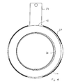
- Fig. 6 This ring, that is, the material measure 10 of the angle sensor 3, shown in plan view.
- the double eccentric shape of the material measure 10 is well visible: both an inner contour 36 and an outer contour 37 of the material measure 10 is formed eccentrically.
- the assembly of the rolling bearing assembly 1 according to Fig. 5 begins, for example, with the impressions of the shell core 11 in the annular circuit board 24. Subsequently, a non-magnetic spacer 38 is inserted into the shell core 11, which has the task to ensure an exactly constant distance between the U-legs 12,14. For the same purpose is in the finished assembled rolling bearing assembly 1, as in Fig. 5 shown, radially outside the shell core 11, between the Holding element 17 and the outer support ring 19, a spring element 39 is provided, which presses the outer U-leg 12 against the U-base 13 parallel spacer 38.
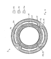
- FIGS. 7 and 8 Different variants of each of a layer 27 of the sensor ring 9 are shown, which for both the embodiment of the FIGS. 1 to 4 as well as for the embodiment according to the Figures 5 and 6 are suitable. While in the example after FIG. 7 , as in the example after Fig. 4 , only either two sine coils 22 or two cosine coils 23 are arranged on the layer 27, the layer 27 after Fig. 8 four coils, namely two sine coils 22 and two cosine coils 23, each of these receiving coils 22,23 extending over approximately 90 °. All layers 27 of the circuit board 24 after FIG. 8 are congruent, that is, without rotation to each other, arranged.
Landscapes
- Engineering & Computer Science (AREA)
- General Engineering & Computer Science (AREA)
- Mechanical Engineering (AREA)
- Physics & Mathematics (AREA)
- General Physics & Mathematics (AREA)
- Rolling Contact Bearings (AREA)
- Transmission And Conversion Of Sensor Element Output (AREA)
Claims (22)
- Ensemble (1) de palier de roulement doté d'un capteur (3) d'angle et comprenant :un palier de roulement (2) présentant deux bagues de palier (4, 5) concentriques par rapport à un axe de rotation (R), à savoir une bague intérieure (4) et une bague extérieure (5), des corps de roulement (6) étant disposés entre les bagues de palier (4, 5),un capteur (3) d'angle raccordé au palier de roulement (2) et prévu pour détecter la position angulaire de la première bague de palier (4) par rapport à la deuxième bague de palier (5) et qui présente une bague de capteur (9) raccordée à l'une des bagues de palier (4, 5) et un ensemble de mesure (10) raccordé à rotation solidaire à la deuxième bague de palier (5, 4),des bobines (21, 22, 23), à savoir au moins une bobine émettrice (21) et au moins une bobine réceptrice (22, 23) étant disposées sur la bague de palier (9), un signal pouvant être transmis par l'intermédiaire d'un circuit magnétique entre la bobine émettrice (21) et la bobine réceptrice (22, 23), l'ensemble de mesure (10) définissant une réductance variable dans le circuit magnétique,
caractérisé en ce quela bobine émettrice (21) entoure l'axe de rotation (R) et est disposée dans une âme de coquille (11) raccordée à l'une des bagues de palier (4, 5), formant une partie de circuit magnétique, présentant une section transversale en forme de U, annulaire et concentrique par rapport à l'axe de rotation (R),en ce que l'ensemble de mesure (10) est configuré comme bague qui forme une liaison magnétiquement conductrice entre les branches (12, 14) de l'âme de coquille (11) en forme de U eten ce qu'une bobine réceptrice (22, 23) est disposée en partie à l'intérieur et en partie à l'extérieur de l'âme de coquille (11). - Ensemble (1) de palier de roulement selon la revendication 1, caractérisé en ce qu'au moins une bobine (21, 22, 23) est configurée comme circuit imprimé.
- Ensemble (1) de palier de roulement selon la revendication 2, caractérisé en ce que différentes bobines réceptrices (22, 23) sont prévues, à savoir des bobines sinusoïdales (22) et des bobines cosinusoïdales (23) formées par plusieurs enroulements (28, 29), les enroulements (28) des bobines sinusoïdales (22) et les enroulements (29) des bobines cosinusoïdales (23) étant disposés en alternance sur des couches superposées (27) d'un circuit imprimé configuré comme carte de circuit (24) multicouche.
- Ensemble (1) de palier de roulement selon la revendication 3, caractérisé en ce que deux ensembles d'enroulement d'une bobine sinusoïdale (22), constitués chacun de plusieurs enroulements (28) disposés les uns à l'intérieur des autres et deux ensembles d'enroulement d'une bobine cosinusoïdale (23), constitués de plusieurs enroulements (29) situés les uns à l'intérieur des autres, sont disposés sur chaque couche (27).
- Ensemble (1) de palier de roulement selon la revendication 2, caractérisé en ce que différentes bobines réceptrices (22, 23) sont prévues, à savoir des bobines sinusoïdales (22) et des bobines cosinusoïdales (23) formées par plusieurs enroulements (28, 29), les enroulements (28) des bobines sinusoïdales (22) et les enroulements (29) des bobines cosinusoïdales (23) étant disposés sur une couche commune (27) d'un circuit imprimé configuré comme carte de circuit (24) multicouche.
- Ensemble (1) de palier de roulement selon la revendication 5, caractérisé en ce que deux enroulements (28) d'une bobine sinusoïdale (22) et deux enroulements (29) d'une bobine cosinusoïdale (23) sont disposés sur une couche (27).
- Ensemble (1) de palier de roulement selon la revendication 1, caractérisé par une unité de commande et d'évaluation (31) raccordée aux bobines (21, 22, 23) et disposée à l'extérieur du capteur (3) d'angle.
- Ensemble (1) de palier de roulement selon la revendication 1, caractérisé en ce que le palier de roulement (2) est configuré comme palier radial, la bague de capteur (9) étant raccordée à la bague extérieure (5) formant une première bague de palier et l'ensemble de mesure (10) présentant la forme d'une bague décentrée par rapport à l'axe de rotation (R) étant raccordée à la bague intérieure (4) formant une deuxième bague de palier.
- Ensemble (1) de palier de roulement selon la revendication 1, caractérisé en ce que le palier de roulement (2) est configuré comme palier radial, la bague de capteur (9) étant raccordée à la bague extérieure (5) formant une première bague de palier et l'ensemble de mesure (10) qui présente la forme d'une bague présentant des surfaces de recouvrement non parallèles et concentriques par rapport à l'axe de rotation (R) est reliée à la bague intérieure (4) formant la deuxième bague de palier.
- Ensemble (1) de palier de roulement selon la revendication 8, caractérisé en ce que la bague de capteur (9) présente un contour décentré tant sur son côté radialement intérieur que son côté radialement extérieur.
- Ensemble (1) de palier de roulement selon l'une des revendications 8 à 10, caractérisé en ce que l'âme de coquille (11) est traversée plusieurs fois sur la branche radialement extérieure (12) du U.
- Ensemble (1) de palier de roulement selon l'une des revendications 8 à 11, caractérisé en ce que l'âme de coquille (11) est entourée radialement par un élément de maintien (17) fixé sur la bague extérieure (5).
- Ensemble (1) de palier de roulement selon la revendication 12, caractérisé en ce que l'élément de maintien (17) est configuré sous la forme d'une pièce en matière synthétique moulée par injection.
- Ensemble (1) de palier de roulement selon les revendications 12 ou 13, caractérisé en ce que l'élément de maintien (17) est entouré radialement par une bague de soutien (19) en métal qui est en contact avec un côté frontal de la bague extérieure (5).
- Ensemble (1) de palier de roulement selon la revendication 14, caractérisé en ce que la bague de soutien (19) déborde de l'âme de coquille (11) dans la direction axiale, la bague de soutien (19) présentant sur sa partie qui déborde de l'âme de coquille (11) une patte de fixation (32) coudée radialement vers l'intérieur sur sa périphérie pour le maintien d'un câble (30) raccordé à la bague de capteur (9).
- Ensemble (1) de palier de roulement selon la revendication 14, caractérisé en ce que la bague de soutien (19) déborde de l'âme de coquille (11) dans la direction axiale, la bague de soutien (19) présentant à sa périphérie une découpe (33) par laquelle un support (34) de câble, en forme de ruban et formé d'un seul tenant avec l'âme de coquille (11) déborde radialement vers l'extérieur.
- Ensemble (1) de palier de roulement selon les revendications 8 ou 9, caractérisé en ce que la branche radialement extérieure (12) du U de l'âme de coquille (11) est disposée radialement à l'extérieure de la bague intérieure (4) et la branche radialement intérieure (14) du U de l'âme de coquille (11) est disposée radialement à l'intérieur de la piste de déplacement (15) des corps de roulement (6) formée par la bague intérieure (4).
- Ensemble (1) de palier de roulement selon les revendications 8 ou 9, caractérisé en ce qu'un interstice d'étanchéité (16) est formé entre la branche radialement intérieure (14) du U de l'âme de coquille (11) et le côté frontal de la bague intérieure (4).
- Ensemble (1) de palier de roulement selon la revendication 1, caractérisé par un disque d'écartement (38) disposé entre les branches (12, 14) de l'âme de coquille (11) en forme de U, en matériau non magnétique.
- Ensemble (1) de palier de roulement selon la revendication 19, caractérisé par un élément élastique (39) disposé à l'extérieur de l'âme de coquille (11) et repoussant la branche extérieure (12) du U contre le disque d'écartement (38).
- Ensemble de capteur doté d'un capteur (3) d'angle, et comportant une bague de capteur (9) qui entoure un axe de rotation (R) et un ensemble de mesure (10) apte à tourner par rapport à la bague de capteur,
des bobines (21, 22, 23), à savoir au moins une bobine émettrice (21) et au moins une bobine réceptrice (22, 23) sont disposées sur la bague de capteur (9), un signal pouvant être transmis par l'intermédiaire d'un circuit magnétique entre la bobine émettrice (21) et la bobine réceptrice (22, 23) et une réductance variable étant définie dans le circuit magnétique par l'ensemble de mesure (10),
la bobine émettrice (21) étant disposée dans une âme de coquille (11) formant une partie du circuit magnétique, présentant une section transversale en forme de U, annulaire et concentrique par rapport à l'axe de rotation (R),
l'ensemble de mesure (10) étant configuré comme bague qui ferme le circuit magnétique entre les branches (12, 14) de l'âme de coquille (11) en forme de U et
une bobine réceptrice (22, 23) étant disposée en partie à l'intérieur de l'âme de coquille (11). - Procédé de montage d'un ensemble de palier de roulement (1) doté d'un capteur (3) d'angle, le procédé présentant les étapes suivantes :un palier de rotation (2) configuré comme palier radial et doté de deux bagues de palier (4, 5), à savoir une bague intérieure (4) et une bague extérieure (5), une rainure (18) périphérique, adjacente à une piste de déplacement (15) des corps de roulement, étant formée dans chaque bague de palier (4, 5), est formé,une bague décentrée par rapport à l'axe de rotation (R) du palier de roulement (2) et fonctionnant comme ensemble de mesure (10) est encliquetée dans la rainure périphérique (18) de la bague intérieure (4),un élément de maintien (17) configuré comme pièce en matière synthétique moulée par injection est inséré dans une bague de soutien (19) en métal dont le diamètre extérieur correspond au plus au diamètre extérieur de la bague extérieure (5) du palier de roulement (2),l'élément de maintien (17) est encliqueté dans la rainure périphérique (18) de la bague extérieure (5), la bague de soutien (19) venant buter contre un côté frontal de la bague extérieure (5),une bague de capteur (9) configurée comme circuit imprimé et prévue pour exécuter une mesure d'angle selon le principe de la réductance variable et sur laquelle des bobines (21, 22, 23), à savoir au moins une bobine émettrice (21) et au moins une bobine réceptrice (22, 23) sont disposées, est enfichée sur l'élément de maintien (17) de telle sorte qu'elle soit située en partie dans un interstice (20) de forme annulaire, voisin de l'élément de maintien (17), radialement directement à l'intérieur de la bague de soutien (19) et en partie radialement à l'intérieur de l'élément de maintien (17), des parties d'une fente (26) qui décrit un espace annulaire restant entre la périphérique intérieure de l'élément de maintien (17) et les parties de la bague de capteur (9) disposée radialement à l'intérieur de l'élément de maintien (17),une âme de coquille (11), annulaire, de section transversale en forme de U et ouverte en direction du côté frontal du palier de roulement (2), en un matériau ferromagnétique, qui forme de même que la bague décentrée (10) en composant d'un circuit magnétique,
est enfichée dans la direction axiale sur l'ensemble constitué de l'élément de maintien (17), de la bague de soutien (19) et de la bague de capteur (9) et est encliquetée sur cet ensemble, une branche disposée radialement à l'extérieur (12) du U de l'âme de coquille (11), qui repose contre la périphérie intérieure de l'élément de maintien (17), s'engageant dans la fente (26) adjacente à ce dernier tandis qu'une branche intérieure (14) du U de l'âme de coquille (11) est entièrement disposée radialement à l'intérieur de la bague de capteur (9).
Applications Claiming Priority (2)
| Application Number | Priority Date | Filing Date | Title |
|---|---|---|---|
| DE102010018207 | 2010-04-26 | ||
| PCT/EP2011/056567 WO2011134955A2 (fr) | 2010-04-26 | 2011-04-26 | Système de palier à roulement à capteur d'angle |
Publications (2)
| Publication Number | Publication Date |
|---|---|
| EP2564084A2 EP2564084A2 (fr) | 2013-03-06 |
| EP2564084B1 true EP2564084B1 (fr) | 2014-12-31 |
Family
ID=44626343
Family Applications (1)
| Application Number | Title | Priority Date | Filing Date |
|---|---|---|---|
| EP11719503.2A Not-in-force EP2564084B1 (fr) | 2010-04-26 | 2011-04-26 | Système de palier à roulement à capteur d'angle |
Country Status (4)
| Country | Link |
|---|---|
| US (1) | US9329022B2 (fr) |
| EP (1) | EP2564084B1 (fr) |
| CN (1) | CN102859218B (fr) |
| WO (1) | WO2011134955A2 (fr) |
Families Citing this family (28)
| Publication number | Priority date | Publication date | Assignee | Title |
|---|---|---|---|---|
| IT1396964B1 (it) * | 2009-11-12 | 2012-12-20 | Bortolin Kemo Spa | Macchina per la depallettizzazione di un carico multistrato. |
| DE102010027900A1 (de) * | 2010-04-19 | 2011-10-20 | Dr. Johannes Heidenhain Gmbh | Baueinheit für eine Winkelmesseinrichtung |
| US20140269240A1 (en) * | 2011-10-25 | 2014-09-18 | Hewlett-Packard Development Company, L.P. | Drive carrier substrate |
| CN102699238A (zh) * | 2012-05-28 | 2012-10-03 | 欣灵电气股份有限公司 | 钢筋折弯机的角度传感器装置 |
| DE102012223942A1 (de) * | 2012-12-20 | 2014-06-26 | Schaeffler Technologies Gmbh & Co. Kg | Sensoranordnung mit einem Winkelsensor sowie Wälzlageranordnung |
| DE102013207621B4 (de) | 2013-04-26 | 2015-04-09 | Schaeffler Technologies AG & Co. KG | Winkelmessung, insbesondere berührungslos, mit Einzelsensoren |
| US9638595B2 (en) * | 2013-11-21 | 2017-05-02 | Nsk Ltd. | Torque measuring unit for electric power steering device and method of assembling the same |
| DE102014210013A1 (de) | 2014-05-26 | 2015-11-26 | Schaeffler Technologies AG & Co. KG | Magnetische Platine und Verfahren zu deren Herstellung |
| DE102014210014A1 (de) * | 2014-05-26 | 2015-11-26 | Schaeffler Technologies AG & Co. KG | Resolverlager, Resolverstator und Verfahren zu dessen Herstellung |
| CN103982556B (zh) * | 2014-05-28 | 2016-05-04 | 浙江师范大学 | 一种用于风力发电机的转速自监测的球轴承 |
| CN103982557B (zh) * | 2014-05-28 | 2016-05-11 | 浙江师范大学 | 一种具有自测量系统的球轴承 |
| CN103994142B (zh) * | 2014-05-28 | 2016-05-04 | 浙江师范大学 | 一种用于电力设施的大尺度球轴承组件 |
| DE102014212124B3 (de) * | 2014-06-24 | 2015-05-21 | Schaeffler Technologies AG & Co. KG | Übertrager, Verfahren zu dessen Herstellung und Wälzlager mit integriertem Übertrager |
| DE102014212319A1 (de) | 2014-06-26 | 2015-12-31 | Schaeffler Technologies AG & Co. KG | Nockenwellenversteller und Verfahren zur Bestimmung der Einstellung eines Nockenwellenverstellers |
| DE102015208838B4 (de) | 2015-05-13 | 2020-07-09 | Schaeffler Technologies AG & Co. KG | Wälzlageranordnung |
| DE102015208837B4 (de) * | 2015-05-13 | 2017-03-30 | Schaeffler Technologies AG & Co. KG | Sensoranordnung mit einem Winkelsensor sowie Wälzlageranordnung mit Sensoranordnung |
| CN106438685A (zh) * | 2016-09-30 | 2017-02-22 | 江苏磊源智能科技有限公司 | 内芯平面设有齿轮或叶轮的轴承 |
| DE102017103414B3 (de) * | 2017-02-20 | 2018-02-15 | Schaeffler Technologies AG & Co. KG | Resolverlageranordnung |
| JP6361769B1 (ja) * | 2017-03-28 | 2018-07-25 | Tdk株式会社 | 位置予測装置及び位置検出装置 |
| US20190113086A1 (en) * | 2017-10-15 | 2019-04-18 | Roy Rosser | Reciprocating Action Drive with Magnetically Hinged Overrunning Clutch |
| DE102017130335B3 (de) * | 2017-12-18 | 2018-12-27 | Schaeffler Technologies AG & Co. KG | Lageranordnungen und Modulträger für diese |
| DE102017130644A1 (de) | 2017-12-20 | 2019-06-27 | Schaeffler Technologies AG & Co. KG | Lagereinheit mit einem Lager und einer Sensorik zur Erfassung der Drehzahl und Drehrichtung einer elektrischen Maschine |
| DE102018117314A1 (de) * | 2018-07-18 | 2020-01-23 | Schaeffler Technologies AG & Co. KG | Sensoreinheit und Lageranordnung mit einer derartigen Sensoreinheit |
| US10927896B2 (en) | 2019-07-15 | 2021-02-23 | Schaeffler Tehnologies AG & Co. KG | Motor assembly and method of assembling motor |
| DE102019125801B4 (de) * | 2019-09-25 | 2025-07-03 | Dr. Ing. H.C. F. Porsche Aktiengesellschaft | Wälzlager mit Sensor und Antriebseinheit |
| DE102021105566A1 (de) | 2020-03-24 | 2021-09-30 | Honeywell International Inc. | Drehgeber |
| WO2022132229A1 (fr) * | 2020-12-14 | 2022-06-23 | Microchip Technology Inc. | Capteur inductif angulaire haute résolution et procédé d'utilisation associé |
| DE102021201679A1 (de) * | 2021-02-23 | 2022-08-25 | Dr. Johannes Heidenhain Gmbh | Winkelmesssystem |
Family Cites Families (13)
| Publication number | Priority date | Publication date | Assignee | Title |
|---|---|---|---|---|
| US3587325A (en) * | 1969-04-07 | 1971-06-28 | Hunter Eng Co | Control for dynamic wheel alignnment apparatus |
| US3678493A (en) * | 1970-09-21 | 1972-07-18 | Borg Warner | Machinery shaft radial position monitor/alarm system |
| FR2678691B1 (fr) | 1991-07-05 | 1995-04-21 | Skf France | Dispositif de capteur de vitesse de rotation pour roulements et roulement equipe d'un tel dispositif. |
| FR2833663B1 (fr) * | 2001-12-19 | 2004-02-27 | Roulements Soc Nouvelle | Roulement comprenant un ensemble de transmission d'informations sans fil |
| FR2841990B1 (fr) | 2002-07-02 | 2005-07-29 | Skf Ab | Dispositif de palier a roulement instrumente et moteur electrique ainsi equipe |
| EP1574823A4 (fr) | 2002-12-20 | 2008-06-11 | Jtekt Corp | Unite de roulement a rouleaux equipee d'un capteur |
| JP2005061943A (ja) | 2003-08-11 | 2005-03-10 | Minebea Co Ltd | バリアブルリラクタンス型レゾルバ |
| US8212551B2 (en) * | 2004-08-03 | 2012-07-03 | Ntn Corporation | Bearing with absolute angle sensor |
| US7100434B2 (en) * | 2004-10-07 | 2006-09-05 | Ford Global Technologies, Llc | Devices and methods for simulating tire non-uniformity forces for vehicle vibration sensitivity measurements and tuning |
| DE102005059393A1 (de) * | 2005-12-13 | 2007-06-14 | Schaeffler Kg | Radlager mit Sensor |
| CN200944044Y (zh) * | 2006-09-15 | 2007-09-05 | 上海联合滚动轴承有限公司 | 轴承内圈挡边角度测量装置 |
| JP4987031B2 (ja) * | 2009-04-27 | 2012-07-25 | 日立オートモティブシステムズ株式会社 | 内燃機関のバルブタイミング制御装置 |
| US20110207578A1 (en) * | 2010-02-23 | 2011-08-25 | Avago Technologies Ecbu (Singapore) Pte, Ltd. | Harmonic Gear Multi-Turn Encoder |
-
2011
- 2011-04-26 WO PCT/EP2011/056567 patent/WO2011134955A2/fr not_active Ceased
- 2011-04-26 EP EP11719503.2A patent/EP2564084B1/fr not_active Not-in-force
- 2011-04-26 US US13/643,465 patent/US9329022B2/en not_active Expired - Fee Related
- 2011-04-26 CN CN201180021309.3A patent/CN102859218B/zh not_active Expired - Fee Related
Also Published As
| Publication number | Publication date |
|---|---|
| US9329022B2 (en) | 2016-05-03 |
| CN102859218A (zh) | 2013-01-02 |
| US20130113470A1 (en) | 2013-05-09 |
| WO2011134955A2 (fr) | 2011-11-03 |
| WO2011134955A3 (fr) | 2011-12-29 |
| EP2564084A2 (fr) | 2013-03-06 |
| CN102859218B (zh) | 2015-05-20 |
Similar Documents
| Publication | Publication Date | Title |
|---|---|---|
| EP2564084B1 (fr) | Système de palier à roulement à capteur d'angle | |
| EP2743662B1 (fr) | Dispositif comprenant une installation de capteurs de couple et en option une installation de capteurs d'angle de direction pour un véhicule automobile | |
| EP2449276B1 (fr) | Palier à unité de production d'énergie | |
| EP1464935B1 (fr) | Appareil pour détecter le couple de rotation d'un arbre rotatif | |
| DE69412735T2 (de) | Aufnehmer zur berührungsfreien Bestimmung der Drehung eines rotierenden Elementes | |
| WO2007079996A1 (fr) | Unite a aimant destinee a etre fixee sur un arbre | |
| WO2012152538A1 (fr) | Palier comprenant une unité génératrice d'énergie, en particulier un palier à rotule pour le support d'un rouleau | |
| WO2015180711A1 (fr) | Palier de résolveur, stator de résolveur et procédé de fabrication | |
| EP2631608B1 (fr) | Encodeur | |
| EP3683551A1 (fr) | Unité de balayage pour un dispositif de mesure d'angle | |
| DE102004056049A1 (de) | Sensor und Verfahren zur Herstellung eines Sensors | |
| WO2012152537A1 (fr) | Palier à roulement, en particulier palier à roulement à deux rangées, comprenant une unité génératrice d'énergie, en particulier pour le support d'un rouleau | |
| WO2016180411A1 (fr) | Ensemble capteur comprenant un capteur angulaire et ensemble palier à roulement comprenant un ensemble capteur | |
| DE19651660A1 (de) | Mikroelektromotor | |
| EP2644921A1 (fr) | Ensemble de roulement avec capteur et codeur fixé à la bague rotative d'un roulement incorporé dans un logement de roulement | |
| EP1895277A1 (fr) | Codeur rotatif avec aide de montage | |
| DE102008013377A1 (de) | Winkelmesssystem und Verfahren zur Herstellung eines Winkelmesssystems | |
| EP0998658A1 (fr) | Capteur de position magnetique | |
| EP2232678A2 (fr) | Micromoteur électrique à bobine intégrée | |
| DE20305732U1 (de) | Vorrichtung zum Bestimmen eines auf eine Welle ausgeübten Drehmoments | |
| DE102019007681A1 (de) | Abtasteinheit für eine Winkelmesseinrichtung | |
| EP1424544B1 (fr) | Appareil pour détecter le couple de rotation d'un arbre rotatif | |
| EP2257768B1 (fr) | Système de mesure angulaire | |
| DE102012223942A1 (de) | Sensoranordnung mit einem Winkelsensor sowie Wälzlageranordnung | |
| DE112019005594T5 (de) | Vorrichtung zur bestimmung der winkelposition des rotors einer drehenden elektrischen maschine |
Legal Events
| Date | Code | Title | Description |
|---|---|---|---|
| PUAI | Public reference made under article 153(3) epc to a published international application that has entered the european phase |
Free format text: ORIGINAL CODE: 0009012 |
|
| 17P | Request for examination filed |
Effective date: 20121126 |
|
| AK | Designated contracting states |
Kind code of ref document: A2 Designated state(s): AL AT BE BG CH CY CZ DE DK EE ES FI FR GB GR HR HU IE IS IT LI LT LU LV MC MK MT NL NO PL PT RO RS SE SI SK SM TR |
|
| DAX | Request for extension of the european patent (deleted) | ||
| RAP1 | Party data changed (applicant data changed or rights of an application transferred) |
Owner name: SCHAEFFLER TECHNOLOGIES GMBH & CO. KG |
|
| REG | Reference to a national code |
Ref country code: DE Ref legal event code: R079 Ref document number: 502011005480 Country of ref document: DE Free format text: PREVIOUS MAIN CLASS: F16C0041000000 Ipc: G01B0007300000 |
|
| GRAP | Despatch of communication of intention to grant a patent |
Free format text: ORIGINAL CODE: EPIDOSNIGR1 |
|
| RIC1 | Information provided on ipc code assigned before grant |
Ipc: G01B 7/30 20060101AFI20140627BHEP |
|
| INTG | Intention to grant announced |
Effective date: 20140715 |
|
| GRAS | Grant fee paid |
Free format text: ORIGINAL CODE: EPIDOSNIGR3 |
|
| GRAA | (expected) grant |
Free format text: ORIGINAL CODE: 0009210 |
|
| AK | Designated contracting states |
Kind code of ref document: B1 Designated state(s): AL AT BE BG CH CY CZ DE DK EE ES FI FR GB GR HR HU IE IS IT LI LT LU LV MC MK MT NL NO PL PT RO RS SE SI SK SM TR |
|
| REG | Reference to a national code |
Ref country code: CH Ref legal event code: EP Ref country code: GB Ref legal event code: FG4D Free format text: NOT ENGLISH |
|
| REG | Reference to a national code |
Ref country code: IE Ref legal event code: FG4D Free format text: LANGUAGE OF EP DOCUMENT: GERMAN |
|
| REG | Reference to a national code |
Ref country code: AT Ref legal event code: REF Ref document number: 704665 Country of ref document: AT Kind code of ref document: T Effective date: 20150215 |
|
| REG | Reference to a national code |
Ref country code: DE Ref legal event code: R096 Ref document number: 502011005480 Country of ref document: DE Effective date: 20150226 |
|
| RAP2 | Party data changed (patent owner data changed or rights of a patent transferred) |
Owner name: SCHAEFFLER TECHNOLOGIES AG & CO. KG |
|
| REG | Reference to a national code |
Ref country code: DE Ref legal event code: R081 Ref document number: 502011005480 Country of ref document: DE Owner name: SCHAEFFLER TECHNOLOGIES AG & CO. KG, DE Free format text: FORMER OWNER: SCHAEFFLER TECHNOLOGIES GMBH & CO. KG, 91074 HERZOGENAURACH, DE Effective date: 20150122 |
|
| PG25 | Lapsed in a contracting state [announced via postgrant information from national office to epo] |
Ref country code: NO Free format text: LAPSE BECAUSE OF FAILURE TO SUBMIT A TRANSLATION OF THE DESCRIPTION OR TO PAY THE FEE WITHIN THE PRESCRIBED TIME-LIMIT Effective date: 20150331 Ref country code: FI Free format text: LAPSE BECAUSE OF FAILURE TO SUBMIT A TRANSLATION OF THE DESCRIPTION OR TO PAY THE FEE WITHIN THE PRESCRIBED TIME-LIMIT Effective date: 20141231 Ref country code: LT Free format text: LAPSE BECAUSE OF FAILURE TO SUBMIT A TRANSLATION OF THE DESCRIPTION OR TO PAY THE FEE WITHIN THE PRESCRIBED TIME-LIMIT Effective date: 20141231 |
|
| REG | Reference to a national code |
Ref country code: NL Ref legal event code: VDEP Effective date: 20141231 |
|
| REG | Reference to a national code |
Ref country code: LT Ref legal event code: MG4D |
|
| PG25 | Lapsed in a contracting state [announced via postgrant information from national office to epo] |
Ref country code: GR Free format text: LAPSE BECAUSE OF FAILURE TO SUBMIT A TRANSLATION OF THE DESCRIPTION OR TO PAY THE FEE WITHIN THE PRESCRIBED TIME-LIMIT Effective date: 20150401 Ref country code: SE Free format text: LAPSE BECAUSE OF FAILURE TO SUBMIT A TRANSLATION OF THE DESCRIPTION OR TO PAY THE FEE WITHIN THE PRESCRIBED TIME-LIMIT Effective date: 20141231 Ref country code: RS Free format text: LAPSE BECAUSE OF FAILURE TO SUBMIT A TRANSLATION OF THE DESCRIPTION OR TO PAY THE FEE WITHIN THE PRESCRIBED TIME-LIMIT Effective date: 20141231 Ref country code: HR Free format text: LAPSE BECAUSE OF FAILURE TO SUBMIT A TRANSLATION OF THE DESCRIPTION OR TO PAY THE FEE WITHIN THE PRESCRIBED TIME-LIMIT Effective date: 20141231 Ref country code: LV Free format text: LAPSE BECAUSE OF FAILURE TO SUBMIT A TRANSLATION OF THE DESCRIPTION OR TO PAY THE FEE WITHIN THE PRESCRIBED TIME-LIMIT Effective date: 20141231 |
|
| PG25 | Lapsed in a contracting state [announced via postgrant information from national office to epo] |
Ref country code: NL Free format text: LAPSE BECAUSE OF FAILURE TO SUBMIT A TRANSLATION OF THE DESCRIPTION OR TO PAY THE FEE WITHIN THE PRESCRIBED TIME-LIMIT Effective date: 20141231 |
|
| PG25 | Lapsed in a contracting state [announced via postgrant information from national office to epo] |
Ref country code: ES Free format text: LAPSE BECAUSE OF FAILURE TO SUBMIT A TRANSLATION OF THE DESCRIPTION OR TO PAY THE FEE WITHIN THE PRESCRIBED TIME-LIMIT Effective date: 20141231 Ref country code: RO Free format text: LAPSE BECAUSE OF FAILURE TO SUBMIT A TRANSLATION OF THE DESCRIPTION OR TO PAY THE FEE WITHIN THE PRESCRIBED TIME-LIMIT Effective date: 20141231 Ref country code: SK Free format text: LAPSE BECAUSE OF FAILURE TO SUBMIT A TRANSLATION OF THE DESCRIPTION OR TO PAY THE FEE WITHIN THE PRESCRIBED TIME-LIMIT Effective date: 20141231 Ref country code: CZ Free format text: LAPSE BECAUSE OF FAILURE TO SUBMIT A TRANSLATION OF THE DESCRIPTION OR TO PAY THE FEE WITHIN THE PRESCRIBED TIME-LIMIT Effective date: 20141231 |
|
| PG25 | Lapsed in a contracting state [announced via postgrant information from national office to epo] |
Ref country code: IS Free format text: LAPSE BECAUSE OF FAILURE TO SUBMIT A TRANSLATION OF THE DESCRIPTION OR TO PAY THE FEE WITHIN THE PRESCRIBED TIME-LIMIT Effective date: 20150430 Ref country code: PL Free format text: LAPSE BECAUSE OF FAILURE TO SUBMIT A TRANSLATION OF THE DESCRIPTION OR TO PAY THE FEE WITHIN THE PRESCRIBED TIME-LIMIT Effective date: 20141231 |
|
| REG | Reference to a national code |
Ref country code: DE Ref legal event code: R097 Ref document number: 502011005480 Country of ref document: DE |
|
| PG25 | Lapsed in a contracting state [announced via postgrant information from national office to epo] |
Ref country code: DK Free format text: LAPSE BECAUSE OF FAILURE TO SUBMIT A TRANSLATION OF THE DESCRIPTION OR TO PAY THE FEE WITHIN THE PRESCRIBED TIME-LIMIT Effective date: 20141231 Ref country code: EE Free format text: LAPSE BECAUSE OF FAILURE TO SUBMIT A TRANSLATION OF THE DESCRIPTION OR TO PAY THE FEE WITHIN THE PRESCRIBED TIME-LIMIT Effective date: 20141231 |
|
| PLBE | No opposition filed within time limit |
Free format text: ORIGINAL CODE: 0009261 |
|
| STAA | Information on the status of an ep patent application or granted ep patent |
Free format text: STATUS: NO OPPOSITION FILED WITHIN TIME LIMIT |
|
| PG25 | Lapsed in a contracting state [announced via postgrant information from national office to epo] |
Ref country code: MC Free format text: LAPSE BECAUSE OF FAILURE TO SUBMIT A TRANSLATION OF THE DESCRIPTION OR TO PAY THE FEE WITHIN THE PRESCRIBED TIME-LIMIT Effective date: 20141231 Ref country code: LU Free format text: LAPSE BECAUSE OF FAILURE TO SUBMIT A TRANSLATION OF THE DESCRIPTION OR TO PAY THE FEE WITHIN THE PRESCRIBED TIME-LIMIT Effective date: 20150426 |
|
| REG | Reference to a national code |
Ref country code: CH Ref legal event code: PL |
|
| 26N | No opposition filed |
Effective date: 20151001 |
|
| GBPC | Gb: european patent ceased through non-payment of renewal fee |
Effective date: 20150426 |
|
| REG | Reference to a national code |
Ref country code: IE Ref legal event code: MM4A |
|
| PG25 | Lapsed in a contracting state [announced via postgrant information from national office to epo] |
Ref country code: GB Free format text: LAPSE BECAUSE OF NON-PAYMENT OF DUE FEES Effective date: 20150426 Ref country code: LI Free format text: LAPSE BECAUSE OF NON-PAYMENT OF DUE FEES Effective date: 20150430 Ref country code: CH Free format text: LAPSE BECAUSE OF NON-PAYMENT OF DUE FEES Effective date: 20150430 |
|
| PG25 | Lapsed in a contracting state [announced via postgrant information from national office to epo] |
Ref country code: SI Free format text: LAPSE BECAUSE OF FAILURE TO SUBMIT A TRANSLATION OF THE DESCRIPTION OR TO PAY THE FEE WITHIN THE PRESCRIBED TIME-LIMIT Effective date: 20141231 |
|
| REG | Reference to a national code |
Ref country code: FR Ref legal event code: PLFP Year of fee payment: 6 |
|
| PG25 | Lapsed in a contracting state [announced via postgrant information from national office to epo] |
Ref country code: IE Free format text: LAPSE BECAUSE OF NON-PAYMENT OF DUE FEES Effective date: 20150426 |
|
| PG25 | Lapsed in a contracting state [announced via postgrant information from national office to epo] |
Ref country code: MT Free format text: LAPSE BECAUSE OF FAILURE TO SUBMIT A TRANSLATION OF THE DESCRIPTION OR TO PAY THE FEE WITHIN THE PRESCRIBED TIME-LIMIT Effective date: 20141231 |
|
| REG | Reference to a national code |
Ref country code: FR Ref legal event code: PLFP Year of fee payment: 7 |
|
| PG25 | Lapsed in a contracting state [announced via postgrant information from national office to epo] |
Ref country code: HU Free format text: LAPSE BECAUSE OF FAILURE TO SUBMIT A TRANSLATION OF THE DESCRIPTION OR TO PAY THE FEE WITHIN THE PRESCRIBED TIME-LIMIT; INVALID AB INITIO Effective date: 20110426 Ref country code: SM Free format text: LAPSE BECAUSE OF FAILURE TO SUBMIT A TRANSLATION OF THE DESCRIPTION OR TO PAY THE FEE WITHIN THE PRESCRIBED TIME-LIMIT Effective date: 20141231 Ref country code: BG Free format text: LAPSE BECAUSE OF FAILURE TO SUBMIT A TRANSLATION OF THE DESCRIPTION OR TO PAY THE FEE WITHIN THE PRESCRIBED TIME-LIMIT Effective date: 20141231 |
|
| REG | Reference to a national code |
Ref country code: AT Ref legal event code: MM01 Ref document number: 704665 Country of ref document: AT Kind code of ref document: T Effective date: 20160426 |
|
| PG25 | Lapsed in a contracting state [announced via postgrant information from national office to epo] |
Ref country code: CY Free format text: LAPSE BECAUSE OF FAILURE TO SUBMIT A TRANSLATION OF THE DESCRIPTION OR TO PAY THE FEE WITHIN THE PRESCRIBED TIME-LIMIT Effective date: 20141231 |
|
| PG25 | Lapsed in a contracting state [announced via postgrant information from national office to epo] |
Ref country code: BE Free format text: LAPSE BECAUSE OF NON-PAYMENT OF DUE FEES Effective date: 20150430 Ref country code: PT Free format text: LAPSE BECAUSE OF FAILURE TO SUBMIT A TRANSLATION OF THE DESCRIPTION OR TO PAY THE FEE WITHIN THE PRESCRIBED TIME-LIMIT Effective date: 20150501 |
|
| PG25 | Lapsed in a contracting state [announced via postgrant information from national office to epo] |
Ref country code: AT Free format text: LAPSE BECAUSE OF NON-PAYMENT OF DUE FEES Effective date: 20160426 Ref country code: TR Free format text: LAPSE BECAUSE OF FAILURE TO SUBMIT A TRANSLATION OF THE DESCRIPTION OR TO PAY THE FEE WITHIN THE PRESCRIBED TIME-LIMIT Effective date: 20141231 |
|
| REG | Reference to a national code |
Ref country code: FR Ref legal event code: PLFP Year of fee payment: 8 |
|
| PG25 | Lapsed in a contracting state [announced via postgrant information from national office to epo] |
Ref country code: MK Free format text: LAPSE BECAUSE OF FAILURE TO SUBMIT A TRANSLATION OF THE DESCRIPTION OR TO PAY THE FEE WITHIN THE PRESCRIBED TIME-LIMIT Effective date: 20141231 |
|
| PG25 | Lapsed in a contracting state [announced via postgrant information from national office to epo] |
Ref country code: AL Free format text: LAPSE BECAUSE OF FAILURE TO SUBMIT A TRANSLATION OF THE DESCRIPTION OR TO PAY THE FEE WITHIN THE PRESCRIBED TIME-LIMIT Effective date: 20141231 |
|
| PGFP | Annual fee paid to national office [announced via postgrant information from national office to epo] |
Ref country code: ES Payment date: 20190701 Year of fee payment: 9 |
|
| PGFP | Annual fee paid to national office [announced via postgrant information from national office to epo] |
Ref country code: FR Payment date: 20200429 Year of fee payment: 10 |
|
| PGFP | Annual fee paid to national office [announced via postgrant information from national office to epo] |
Ref country code: IT Payment date: 20200424 Year of fee payment: 10 |
|
| REG | Reference to a national code |
Ref country code: DE Ref legal event code: R119 Ref document number: 502011005480 Country of ref document: DE |
|
| PG25 | Lapsed in a contracting state [announced via postgrant information from national office to epo] |
Ref country code: DE Free format text: LAPSE BECAUSE OF NON-PAYMENT OF DUE FEES Effective date: 20201103 |
|
| PG25 | Lapsed in a contracting state [announced via postgrant information from national office to epo] |
Ref country code: FR Free format text: LAPSE BECAUSE OF NON-PAYMENT OF DUE FEES Effective date: 20210430 |
|
| PG25 | Lapsed in a contracting state [announced via postgrant information from national office to epo] |
Ref country code: IT Free format text: LAPSE BECAUSE OF NON-PAYMENT OF DUE FEES Effective date: 20200426 |
|
| P01 | Opt-out of the competence of the unified patent court (upc) registered |
Effective date: 20230522 |
|
| PG25 | Lapsed in a contracting state [announced via postgrant information from national office to epo] |
Ref country code: IT Free format text: LAPSE BECAUSE OF NON-PAYMENT OF DUE FEES Effective date: 20210426 |