EP2564207B1 - Dispositif microfluidique centrifuge et procédé d'immuno-analyse - Google Patents
Dispositif microfluidique centrifuge et procédé d'immuno-analyse Download PDFInfo
- Publication number
- EP2564207B1 EP2564207B1 EP11775191.7A EP11775191A EP2564207B1 EP 2564207 B1 EP2564207 B1 EP 2564207B1 EP 11775191 A EP11775191 A EP 11775191A EP 2564207 B1 EP2564207 B1 EP 2564207B1
- Authority
- EP
- European Patent Office
- Prior art keywords
- chamber
- micro
- analyte
- reaction chamber
- labeling conjugate
- Prior art date
- Legal status (The legal status is an assumption and is not a legal conclusion. Google has not performed a legal analysis and makes no representation as to the accuracy of the status listed.)
- Active
Links
Images


Classifications
-
- G—PHYSICS
- G01—MEASURING; TESTING
- G01N—INVESTIGATING OR ANALYSING MATERIALS BY DETERMINING THEIR CHEMICAL OR PHYSICAL PROPERTIES
- G01N21/00—Investigating or analysing materials by the use of optical means, i.e. using sub-millimetre waves, infrared, visible or ultraviolet light
- G01N21/01—Arrangements or apparatus for facilitating the optical investigation
- G01N21/03—Cuvette constructions
- G01N21/07—Centrifugal type cuvettes
-
- B—PERFORMING OPERATIONS; TRANSPORTING
- B82—NANOTECHNOLOGY
- B82Y—SPECIFIC USES OR APPLICATIONS OF NANOSTRUCTURES; MEASUREMENT OR ANALYSIS OF NANOSTRUCTURES; MANUFACTURE OR TREATMENT OF NANOSTRUCTURES
- B82Y15/00—Nanotechnology for interacting, sensing or actuating, e.g. quantum dots as markers in protein assays or molecular motors
-
- G—PHYSICS
- G01—MEASURING; TESTING
- G01N—INVESTIGATING OR ANALYSING MATERIALS BY DETERMINING THEIR CHEMICAL OR PHYSICAL PROPERTIES
- G01N21/00—Investigating or analysing materials by the use of optical means, i.e. using sub-millimetre waves, infrared, visible or ultraviolet light
- G01N21/62—Systems in which the material investigated is excited whereby it emits light or causes a change in wavelength of the incident light
- G01N21/63—Systems in which the material investigated is excited whereby it emits light or causes a change in wavelength of the incident light optically excited
- G01N21/64—Fluorescence; Phosphorescence
- G01N21/6428—Measuring fluorescence of fluorescent products of reactions or of fluorochrome labelled reactive substances, e.g. measuring quenching effects, using measuring "optrodes"
-
- G—PHYSICS
- G01—MEASURING; TESTING
- G01N—INVESTIGATING OR ANALYSING MATERIALS BY DETERMINING THEIR CHEMICAL OR PHYSICAL PROPERTIES
- G01N33/00—Investigating or analysing materials by specific methods not covered by groups G01N1/00 - G01N31/00
- G01N33/48—Biological material, e.g. blood, urine; Haemocytometers
- G01N33/50—Chemical analysis of biological material, e.g. blood, urine; Testing involving biospecific ligand binding methods; Immunological testing
- G01N33/53—Immunoassay; Biospecific binding assay; Materials therefor
- G01N33/543—Immunoassay; Biospecific binding assay; Materials therefor with an insoluble carrier for immobilising immunochemicals
- G01N33/54366—Apparatus specially adapted for solid-phase testing
Definitions
- Apparatuses and methods consistent with embodiments relate generally to a centrifugal micro-fluidic device and an immunoassay method using the same and, more particularly, to a micro-fluidic device for detection of analytes in a fluid sample using fluorescent nanoparticles, as well as an immunoassay method using the same.
- a micro-fluidic device refers to a device used for conducting biological or chemical reactions using a small amount of fluid.
- a micro-fluidic structure of a micro-fluidic device has at least one independent function and includes a chamber containing a fluid therein, a channel through which the fluid flows and a valve for controlling fluid flow.
- the micro-fluidic structure may be fabricated by combining these components in different ways.
- a device referred to as a "lab-on-a-chip” includes a micro-fluidic structure mounted on a substrate in a chip-like platform. With the lab-on-a-chip, some experiments involving biological or chemical reaction can be conducted on a small chip in order to execute several experimental processes and/or operations on the structure. In order to move a fluid within the micro-fluidic structure, a driving pressure is generally required.
- the driving pressure may be a capillary pressure or pressure generated using an additional pump.
- a disc-type micro-fluidic device referred to as a "Lab CD” (compact disc) or "lab-on-a-disc,” has been proposed.
- the lab-on-a-disc includes a micro-fluidic structure mounted on a disc-type rotational platform which uses centrifugal force to move a fluid in the micro-fluidic structure in order to execute a series of tasks.
- Efforts are ongoing to develop a variety of disc-type micro-fluidic devices capable of rapidly and precisely conducting desired operations in disc-type platforms using centrifugal force.
- US2006/0211055 discloses a microfluidic device which can be incorporated in a rotor.
- a ternary complex comprising a capture moiety, an analyte and a labeling moiety is formed in a binding channel, the complex is released through a separation channel and detected.
- Exemplary embodiments provide a micro-fluidic device for detection of analytes in a fluid sample, such as a liquid specimen. using fluorescent nanoparticles, as well as an immunoassay method using the same.
- a centrifugal micro-fluidic device comprising at least one micro-fluidic structure, the micro-fluidic structure comprising: a sample chamber having a cross-section diameter increasing from a sample introduction inlet toward an outlet for receiving a fluid sample; a separation chamber connected to the sample chamber for centrifugation of the fluid sample for separation of a supernatant containing an analyte from the fluid sample; a first reaction chamber which is connected with the separation chamber and contains at least one labeling conjugate comprising a label and a binder, wherein the hinder specifically binds to the analyte in the supernatant; a second reaction chamber which is connected with the first reaction chamber and contains a capture binder selected from a group comprising: antibody, antigen, receptor, ligand, oligonucleotide, hapten or aptamer; a buffer chamber which is connected with the second reaction chamber and contains an elution buffer, wherein the elution buffer dissociates an
- the labeling conjugate may include at least one label selected from a group including: lanthanide (III) chelates or nanoparticles containing lanthanide (III) chelates; colored polymeric nanoparticles; fluorescent materials or nanoparticles containing the same; phosphorescent materials or nanoparticles containing the same; dye-containing liposomes; enzymes (HRP, ALP, etc.); super para-magnetic materials or nanoparticles containing the same; metal nanoparticles; carbon nanoparticles, etc.
- lanthanide (III) chelates or nanoparticles containing lanthanide (III) chelates colored polymeric nanoparticles; fluorescent materials or nanoparticles containing the same; phosphorescent materials or nanoparticles containing the same; dye-containing liposomes; enzymes (HRP, ALP, etc.); super para-magnetic materials or nanoparticles containing the same; metal nanoparticles; carbon nanoparticles, etc.
- the labeling conjugate may be in a dried solid state.
- the labeling conjugate may include a label causing expression of optical signals of the analyte in the fluid sample, and wherein the label is combined with the analyte.
- the labeling conjugate may contain at least one of various labeling conjugates having individual label substances.
- the labeling conjugate includes a binder and a label, wherein the binder is selected from a group including: an antibody, antigen, receptor, ligand, oligonucleotide, hapten or aptamer.
- the capture binder may be bonded to a reaction site of the analyte different from another reaction site where the labeling conjugate reacts with the analyte.
- the capture binder is selected from a group including: an antibody, antigen, receptor, ligand, oligonucleotide, hapten or aptamer.
- the second reaction chamber may have a detection region in which the capture binder is fixed thereto.
- the micro-fluidic device has a separation chamber connected with the first reaction chamber, wherein the separation chamber separates a supernatant containing an analyte from the fluid sample.
- a detection unit may be positioned outside the micro-fluidic structure, wherein the detection unit includes: a light emission unit emitting light to the detection chamber of the micro-fluidic structure; a light receiving unit receiving the light emitted from the light emitting unit which passed through the detection chamber; and an analysis unit analyzing at least one optical feature of the light received by the light receiving unit and calculating a concentration of at least one analyte in the fluid sample.
- an immunoassay method using the above centrifugal micro-fluidic device including the steps of: injecting a fluid sample into the micro-fluidic device, centrifuging the fluid sample to obtain a supernatant, and transferring the supernatant into a first reaction chamber; combining an analyte contained in the supernatant with a labeling conjugate contained in the first reaction chamber, in order to form a first immune complex, wherein the binder specifically binds to the analyte in the supernatant ; combining the first immune complex with a capture binder selected from a group comprising: antibody, antigen, receptor, ligand, oligonucleotide, hapten or aptamer contained in a second reaction chamber to form a second immune complex ; transferring un-reacted labeling conjugate as well as reaction residues to a waste chamber together with a washing solution fed from a washer chamber; disassociating the labeling
- the labeling conjugate may include at least one label selected from a group including: lanthanide (III) chelates or nanoparticles containing lanthanide (III) chelates; colored polymeric nanoparticles; fluorescent materials or nanoparticles containing the same; phosphorescent materials or nanoparticles containing the same; dye-containing liposomes; enzymes (HRP, ALP, etc.); super para-magnetic materials or nanoparticles containing the same; metal nanoparticles; carbon nanoparticles, etc.
- lanthanide (III) chelates or nanoparticles containing lanthanide (III) chelates colored polymeric nanoparticles; fluorescent materials or nanoparticles containing the same; phosphorescent materials or nanoparticles containing the same; dye-containing liposomes; enzymes (HRP, ALP, etc.); super para-magnetic materials or nanoparticles containing the same; metal nanoparticles; carbon nanoparticles, etc.
- the labeling conjugate may be in a dried solid state.
- the labeling conjugate may include a label causing expression of optical signals of the analyte in the fluid sample, and wherein the label is specifically combined with the analyte.
- the labeling conjugate may be at least one of various labeling conjugates having individual label substances.
- the labeling conjugate includes a binder and a label, wherein the binder is selected from a group including: an antibody, antigen, receptor, ligand, oligonucleotide, hapten or aptamer.
- the capture binder may be bonded to a reaction site of the analyte different from another reaction site where the labeling conjugate reacts with the analyte.
- the capture binder is selected from a group including: an antibody, antigen, receptor, ligand, oligonucleotide, hapten or aptamer.
- the second reaction chamber may further include a detection region in which the capture binder is fixed thereto.
- the fluid sample, supernatant or buffer is transferred by a driving pressure, such as centrifugal force generated by rotation of the micro-fluidic structure.
- Determination of fluorescence of the labeling conjugate may be performed by time-resolved fluorescence measurement that enables fine division (that is, resolution) of time, and which measures fluorescence of light received by a light receiving unit during a resolved time.
- Fluorescence of the light received by the light receiving unit is measured after a pre-determined time delay.
- the micro-fluidic device and the immunoassay method have characteristics in that: i) multiple labeling conjugates containing individual label substances may be at the same time, in turn enabling simultaneous detection of multiple analytes; ii) the labeling conjugate is used in a dried solid state and can be stored at room temperature instead of cold storage, thus improving applicability to actual clinical environments; iii) the number of washing and the numbers of buffers and valves used for opening and closing the channels are decreased, thus being simpler than conventional test procedures; iv) lanthanide (III) chelate-containing nanoparticles with considerable difference between excitation wavelength and emission wavelength are used as the label substance, and fluorescence of the emitted light is determined by time-resolved fluorescence measurement, thereby remarkably enhancing accuracy and sensitivity in fluorescence measurement of the label substance. Therefore, the micro-fluidic device and the immunoassay method using the same according to exemplary embodiments may be used as a rapid on-site inspection technology.
- FIG. 1 is a schematic view illustrating the construction of a micro-fluidic structure, according to an exemplary embodiment.
- a centrifugal micro-fluidic device including: a rotational body 900 and at least one micro-fluidic structure 1000.
- the at least one micro-fluidic structure 1000 further includes a sample chamber 100 for receiving a fluid sample; a separation chamber 200 for centrifugation of the fluid sample to separate a supernatant containing an analyte; a first reaction chamber 300 containing at least one labeling conjugate; a second reaction chamber 400 containing a capture binder; a buffer chamber 500 containing an elution buffer; a waste chamber 600 for receiving impurities including an excess of a first immune complex as well as the analyte; a washer chamber 700 containing a washing solution; and a detection chamber 800 for ultimately receiving the labeling conjugate.
- the micro-fluidic structure also includes a plurality of channels 120 through which the multiple chambers are interconnected; at least one valve (not shown) for opening and closing the plurality of channels; and at least one detection unit 10
- the rotational body 900 used in the exemplary embodiment may include a circular disc-type platform.
- a shape of the platform is not particularly limited to such circular disc form. That is, the rotational body may be a complete circular shape capable of rotating by itself or a rotatable sector shape placed on a rotational frame.
- the platform may be formed using acryl or other plastic materials, each of which is easily formed and has a biologically inactive surface.
- a raw material for fabrication of the rotational body is not particularly limited and may include any materials with chemical or biological stability, optical transparency and/or mechanical workability.
- the platform may be fabricated using at least one material selected from a variety of materials, such as plastic, polymethylmethacrylate (PMMA), glass, mica, silica, or a silica wafer material.
- the plastic material may be chosen in view of its economical merits or simple workability. Commonly available plastic materials include polypropylene, polyacrylate, polyvinylalcohol, polyethylene, PMMA, polycarbonate, etc.
- One or more micro-fluidic structures may be provided on the platform. For instance, after partitioning the platform into several sections, individual micro-fluidic structures may be placed independently of one another on the sections, respectively.
- the platform may include multiple layers of plates (not shown). If a relief structure corresponding to a chamber or a channel is formed on a side at which two plates face each other and two or more relief structures are combined, an empty space and/or channel may be provided inside the platform. Such combination of plates may be achieved using an adhesive, two-sided adhesive tape, ultrasonic welding, etc.
- micro-fluidic structure refers to a general structure which consists of a plurality of chambers, channels and valves designed to induce a fluid flow, as opposed to a particular structural substance. Therefore, the "micro-fluidic structure” may form a specific unit with different functions or performances according to features provided by the arrangement of chambers, channels and/or valves, and/or kinds of materials contained in the structure.
- the micro-fluidic device has a wide variety of applications, such as detection of various chemical compounds, environmentally harmful substances, blood analysis, urine testing, antigen-antibody response-based immunoassay, novel drug candidate searches based on ligand-receptor binding, DNA/RNA analysis, and so forth. Further, the micro-fluidic device may simultaneously detect and analyze at least two analytes.
- a fluid sample such as a blood sample, a supernatant of the fluid sample, a buffer solution, etc. may be transported into separate chambers using centrifugal force generated by rotation of the rotational body 900 as a driving pressure.
- the fluid sample When the fluid sample is fed into the micro-fluidic structure 1000 through a sample introduction inlet 110, the fluid sample is substantially received by the sample chamber 100.
- the sample chamber 100 may offer an empty space in which a fluid sample such as a blood sample is contained.
- the sample chamber 100 has the sample introduction inlet 110 through which the sample is provided to the micro-fluidic structure 1000, and a sample receiving part (not shown).
- the sample receiving part also has an outlet connected to the separation chamber 200.
- the outlet may have a desired shape designed to create capillary pressure that prevents the fluid sample from moving toward the separation chamber 200 when centrifugal force is not being applied.
- the outlet may have a valve mounted thereon in order to control a flow of the fluid sample.
- the sample chamber 100 is fabricated to have a cross-section diameter increasing from the sample introduction inlet 100 toward the outlet, enabling the sample contained in the sample receiving part to easily flow toward the separation chamber 200 by centrifugal force.
- an alternative structure to generate capillary pressure may be placed between the sample introduction inlet 110 and the sample receiving part.
- the alternative structure may be a capillary valve-type structure which passes the sample through the same only when a desired pressure is applied, and it may also serve to block reverse flow of the sample from the sample receiving part toward the sample introduction inlet 110.
- the fluid sample is delivered toward the separation chamber 200 using centrifugal force generated by rotation of the rotational body 900 as a driving pressure.
- the separation chamber 200 is located radially outward from the sample chamber 100; that is, further from a center 160 of the rotational body 900 than the sample chamber 100.
- the sample separation chamber 200 may enable centrifugation of the fluid sample into a supernatant (serum, plasma, etc.) and a precipitate (blood cells).
- the fluid sample in the separation chamber 200 is separated using centrifugal force into a supernatant containing analytes and a precipitate containing other materials.
- the separation chamber 200 for centrifugation of the fluid sample may be configured in different forms.
- the separation chamber 200 may include a supernatant collector (not shown) and a precipitate collector (not shown) as a space being formed at an end of the supernatant collector to collect a precipitate with relatively high specific gravity.
- the supernatant collector has a channel for dispensing the centrifuged supernatant into the first reaction chamber 300.
- a valve may control flow of the sample through the channel.
- Such a valve may be any type of valve selected from different types of micro-fluidic valves.
- the valve may include a so-called "normally closed valve" wherein a channel in which the valve is located is closed to prevent a fluid from flowing unless the valve opens by external power.
- a supernatant metering chamber (not shown) may be placed on the separation chamber 200 to measure an amount of the supernatant.
- the supernatant metering chamber may be designed with a volume sufficient to carry an amount of the supernatant required for testing.
- the supernatant containing the analyte may be transported from the separation chamber 200 to the first reaction chamber 300 through a channel 150 using centrifugal force generated by rotation of the rotational body 900 as a driving pressure.
- the first reaction chamber 300 contains a labeling conjugate, as illustrated by the conceptual exploded view 310 of the first reaction chamber 300 in FIG. 2 and described further below.
- the first reaction chamber 300 is a structure for detecting specific protein, glucose, cholesterol, uric acid, creatinine, alcohol, etc., contained in the supernatant. The detection may be accomplished by antigen-antibody response, ligand-receptor binding, and so forth.
- the labeling conjugate consists of a label and a binder.
- Labels of the labeling conjugate may include, for example, latex beads; metal colloids such as gold colloids, silver colloids, etc.; enzymes (enzyme, HRP, ALP, etc.); colored materials; fluorescent materials or nanoparticles containing the same; phosphorescent materials or nanoparticles containing the same; luminous materials; light emitting materials; dye-containing liposomes; metal nanoparticles; carbon nanoparticles; colored polymeric nanoparticles; super para-magnetic materials or nanoparticles containing the same; lanthanide (III) chelates or nanoparticles containing the same; radioactive isotopes; etc.
- the labels are not particularly limited thereto.
- lanthanide (III) chelate-containing nanoparticles are used as a label substance.
- Non-limiting examples of lanthanide (III) chelates may include europium (Eu), samarium (Sm), dysprosium (Dy), terbium (Tb), etc.
- the binder may include an antibody, antigen, ligand, receptor, oligonucleotide, hapten or aptamer; each of which can be specifically bonded to the analyte in the supernatant.
- the first reaction chamber 300 of the micro-fluidic device may contain a single labeling conjugate containing one kind of label substance in order to detect one analyte; however, the first reaction chamber 300 may also contain several labeling conjugates containing different label substances in order to simultaneously detect plural analytes. For instance, in order to detect four types of distinct analytes at the same time, four types of labeling conjugates containing four different lanthanide (III) chelates as separate label substances, such as Eu, Sm, Dy and Tb, may be contained together in the first reaction chamber 300.
- III lanthanide
- the above configuration may have advantages in that a single micro-fluidic structure 1000 may be used to detect multiple analytes. Multiple analytes may also be detected at the same time by using only one micro-fluidic device having several micro-fluidic structures built therein. This configuration is advantageous when compared to conventional micro-fluidic devices required for detection of multiple analytes.
- the micro-fluidic device may simultaneously detect plural analytes which provides for rapid inspection and economical merits, and is therefore applicable to situations where rapid on-site inspection is desired.
- the labeling conjugate may be present in a liquid or a dried solid phase. Since a liquid phase of the labeling conjugate requires cold transportation and storage in order to retain stability thereof, these requirements make the liquid labeling conjugate less available in practical clinical environments. Therefore, the labeling conjugate is preferably present in a dried solid phase.
- the labeling conjugate in a solid phase When the labeling conjugate in a solid phase is present in the reaction chamber 300, the labeling conjugate may be temporarily fixed to an inner wall of the reaction chamber 300 or a porous support therein (not shown).
- the labeling conjugate fixed to the reaction chamber 300 is lysed by penetration of the supernatant, after which the lysed conjugate is combined with an analyte contained in the supernatant to form a first immune complex 170, as illustrated in FIG. 2 .
- the first immune complex 170 becomes a movable product.
- the rotational body 900 may be preferably shaken several times to the right and left.
- Centrifugal force generated by rotation of the rotational body 900 is used as a driving pressure to transport the supernatant containing the first immune complex 170 toward the second reaction chamber 400 through a channel 150.
- the second reaction chamber 400 is a structure for detecting some materials contained in the supernatant including, for example, specific protein, glucose, cholesterol, uric acid, creatinine, alcohol, etc.
- the materials may be detected using antigen-antibody response or ligand-receptor binding, and so forth.
- the second reaction chamber 400 may contain the capture binder fixed in a detection region, wherein the capture binder is specifically combined with the analyte contained in the supernatant fed from the first reaction chamber 300.
- the first immune complex in the transported supernatant from the first reaction chamber 300 is combined with the capture binder placed in the detection region to form a second immune complex 180, as illustrated by the conceptual exploded view 410 of the second reaction chamber 400 in FIG. 3 .
- the rotational body 900 may be shaken several times to the right and left. Un-reacted labeling conjugate in the reactive solution as well as reaction residues are transferred to the waste chamber 600 together with a washing solution fed from the washer chamber 700, while the second immune complex 180 remains in the second reaction chamber 400, as illustrated by the conceptual exploded view 410 of the second reaction chamber in FIG. 4 .
- an elution buffer is delivered from the buffer chamber 500 located above the second reaction chamber 400 to the second reaction chamber 400 by centrifugal force as a driving pressure.
- the delivered elution buffer dissociates antigen-antibody bonds or ligand-receptor bonds of the second immune complex fixed to the detection region in the second reaction chamber 400, in turn enabling dissociation (or degradation) of the labeling conjugate and the analytes from the fixed capture binder.
- both the labeling conjugate and the capture binder are dissociated with reference to the analytes, as illustrated by the conceptual exploded view 410 of the second reaction chamber in FIG. 5 .
- Conventional technologies generally i) directly determine optical features of a label substance without alternative dissociation of the labeling conjugate from the immune complex; or ii) measure fluorescence of the label substance after dissociating the label substance.
- the exemplary embodiments described herein provide dissociation of the label substance and the capture binder from the second immune complex using the elution buffer from the buffer chamber 500, with reference to the analyte in the second immune complex (see FIG. 5 ).
- Such procedures proposed by the exemplary embodiments herein may improve sensitivity and accuracy in measurement of label substances.
- Other methods for dissociation of a label substance generally include attachment of at least one chemical material corresponding to the label substance to a labeling conjugate and dissociation thereof. These procedures may experience technical difficulties and may not improve accuracy and sensitivity in measurement of the label substance as compared to measurement of a group of various label substances.
- a method for determining optical features of a label substance in a labeling conjugate after dissociation of the labeling conjugate and capture binder from the analyte may be easily embodied compared to conventional processes.
- the label substance may include lanthanide (III) chelate (i.e., Eu) containing nanoparticles as a label substance.
- the method may attain improvements in accuracy and sensitivity in measurement.
- the supernatant containing the labeling conjugate dissociated from the second immune complex is transported into the detection chamber 800 below the second reaction chamber 400 using centrifugal force generated by rotation of the rotational body 900 as a driving pressure.
- optical features are determined by the detection unit 10 (see FIG. 7 ) placed outside the micro-fluidic structure 1000. This process will be more apparent from the following description for a method for immunoassay using the micro-fluidic device according to an exemplary embodiment.
- FIG. 6 is a flowchart illustrating an immunoassay method using the micro-fluidic device according to an exemplary embodiment.
- a process for blood analysis is exemplified.
- whole blood is injected into a sample chamber 100 (S10), and a micro-fluidic structure is rotated to deliver the whole blood toward a separation chamber 200.
- the whole blood is transported from the sample chamber 100 to the separation chamber 200 using centrifugal force generated by rotation of a rotational body 900 as a driving pressure.
- the whole blood fed into the separation chamber 200 is separated by high speed revolution (S20) into a supernatant containing a serum or plasma and precipitate containing blood cells.
- S20 high speed revolution
- blood cells thicker (or heavier) than the serum or plasma may precipitate and move to a precipitate collector, while the supernatant, which is lighter than the blood cells, remains in the supernatant collector.
- the separated supernatant is delivered to a first reaction chamber 300 through a channel by a driving pressure, that is, centrifugal force generated by rotation of the rotational body 900.
- the labeling conjugate is in a dried solid state, is contained in the first reaction chamber 300 and is re-dissolved by inflow of the supernatant and specifically combined with the analyte contained in the supernatant to form a first immune complex (S30).
- the rotational body 900 may be shaken several times to the right and left.
- the supernatant containing the first immune complex is delivered to a second reaction chamber 400 using centrifugal force generated by rotation of the rotational body 900 as a driving pressure.
- the capture binder is contained within the second reaction chamber 400 and may be fixed to the detection region of the second reaction chamber 400.
- the capture binder is specifically combined with the analyte to form a second immune complex (S40).
- the rotational body 900 may be shaken several times to the right and left.
- a valve connected to a washer chamber 700 upstream of the second reaction chamber 400 is opened, and a washing solution is fed into the second reaction chamber 400 through a channel using centrifugal force generated by rotation of the rotational body 900 as a driving pressure (S50).
- a buffer chamber 500 located upstream of the second reaction chamber 400 is opened, and an elution buffer of the buffer chamber is fed into the second reaction chamber 400 through a channel, using centrifugal force generated by rotation of the rotational body 900 as a driving pressure.
- the elution buffer allows the dissociation of the labeling conjugate from the second immune complex, with reference to analytes contained in the second immune complex (S60).
- a valve is opened and the supernatant containing the labeling conjugate is transported into the detection chamber 800 through a channel using centrifugal force generated by rotation of the rotational body 900 as a driving pressure (S70).
- the detection unit 10 placed outside the micro-fluidic structure 1000 starts measurement and analysis of optical features of the label substance of the labeling conjugate (S80).
- Such measurement and analysis of optical features of the label substance may be performed by irradiating the label substance with light at a desired wavelength range, measuring fluorescence of the light emitted from the label substance at a specific wavelength range, analyzing the measured value, and calculating a concentration of an analyte based on the analyzed result.
- Measurement and analysis of optical features of the label substance may be conducted using the detection unit 10 placed outside the micro-fluidic structure 1000, as illustrated in FIG. 7 .
- the detection unit 10 is substantially placed outside the micro-fluidic structure 1000, and multiple units may be present.
- a detection unit may include a light emission unit 11 to radiate light to the detection chamber 800 of the micro-fluidic structure 1000, a light receiving unit 12 to receive light emitted from the detection chamber 800 which absorbs the light emitted from the light receiving part 12, and an analysis part to analyze optical features of the light received by the light receiving part 12 and calculate a concentration of an analyte based on the analyzed result.
- the light emission part 11 may be a light source flashing at a specific frequency including, for example, a semiconductor light emitting device such as an LED or a laser diode (LD), a gas discharge lamp such as a halogen lamp or a xenon lamp, etc.
- a semiconductor light emitting device such as an LED or a laser diode (LD)
- a gas discharge lamp such as a halogen lamp or a xenon lamp, etc.
- the light receiving part 12 generates electrical signals according to an intensity of the light emitted from the detection chamber 800 and may include, for example, a depletion layer photodiode, avalanche photodiode (APD), photomultiplier tube (PMT), etc.
- a depletion layer photodiode avalanche photodiode (APD), photomultiplier tube (PMT), etc.
- APD avalanche photodiode
- PMT photomultiplier tube
- the light emission part 11 is located above the micro-fluidic structure 1000 while the light receiving part 12 is positioned below the micro-fluidic structure 1000, however, the positions of these parts may be switched. Also, a light path may be adjusted using a reflecting mirror or a light guide member.
- the analysis part 13 determines fluorescence of the light received by the light receiving part and calculates a concentration of an analyte using a pre-determined standard curve identifying the determined fluorescence of the received light,.
- lanthanide (III) chelate containing nanoparticles are used as a label substance.
- the following description will be given of using Eu as an example of the lanthanide (III) chelate.
- Eu exhibits a specific optical feature of providing a considerable difference between excitation wavelength and emission wavelength, as illustrated in the graph in FIG. 8 .
- Such an optical feature of Eu that is excited by light at a specific wavelength and discharges light at another wavelength considerably different from the excitation wavelength may remarkably improve accuracy in measurement of fluorescence of the emitting light.
- the optical feature of Eu that is, emission of light at a wavelength considerably different from a wavelength of the incident light may prevent interference of the foreign materials to the emitting light in measurement of the light emitted from the label substance.
- fluorescence of the light emitted from the label substance may be more precisely determined.
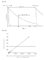
- 'time-resolved fluorescence measurement refers to a method of finely resolving a constant period of time for measurement and measuring fluorescence per resolved time. For instance, as to measurement of fluorescence of the light emitted for 1 second, the fluorescence may be measured at every ms. Therefore, the same cycle may be repeated 1000 times per second (see FIG. 9 ).
- fluorescence measurement is executed in the range of 400 microseconds ( ⁇ s) to 800 ⁇ s. That is, fluorescence measurement is performed after a constant delay time, instead of direct measurement. Indeed, since the detection chamber 800 containing the label substance and/or foreign materials possibly fed into the detection chamber 800, other than the label substance, may also absorb the incident light and emit the absorbed light, the foregoing delay time is required to eliminate influence of the foreign materials and/or the detection chamber.
- Exemplary embodiments propose a method of noticeably improving accuracy and sensitivity in measurement of fluorescence of a label substance by: i) using lanthanide (III) chelate containing nanoparticles (i.e., Eu) as the label substance; and ii) applying time-resolved fluorescence measurement.
- an exemplary embodiment describes an immunoassay method of analytes with superior accuracy and sensitivity by combination of the foregoing procedures, compared to conventional methods for measurement of analytes in fluid specimens.
- a concentration of an analyte may be calculated using a pre-determined standard curve that shows a concentration of the analyte relative to fluorescence of the label substance, as illustrated in FIG. 10 .
Landscapes
- Health & Medical Sciences (AREA)
- Immunology (AREA)
- Life Sciences & Earth Sciences (AREA)
- Chemical & Material Sciences (AREA)
- Engineering & Computer Science (AREA)
- Physics & Mathematics (AREA)
- General Health & Medical Sciences (AREA)
- General Physics & Mathematics (AREA)
- Biochemistry (AREA)
- Pathology (AREA)
- Molecular Biology (AREA)
- Analytical Chemistry (AREA)
- Urology & Nephrology (AREA)
- Hematology (AREA)
- Nanotechnology (AREA)
- Biomedical Technology (AREA)
- Nuclear Medicine, Radiotherapy & Molecular Imaging (AREA)
- Crystallography & Structural Chemistry (AREA)
- Biotechnology (AREA)
- Cell Biology (AREA)
- Optics & Photonics (AREA)
- Microbiology (AREA)
- Chemical Kinetics & Catalysis (AREA)
- Food Science & Technology (AREA)
- Medicinal Chemistry (AREA)
- Investigating, Analyzing Materials By Fluorescence Or Luminescence (AREA)
- Automatic Analysis And Handling Materials Therefor (AREA)
Claims (15)
- Dispositif microfluidique centrifuge comprenant au moins une structure microfluidique, la structure microfluidique comprenant:une chambre à échantillon destinée à recevoir un échantillon fluide et présentant un diamètre de section transversale croissant entre une entrée d'introduction d'échantillon et une sortie;une chambre de séparation reliée à la chambre à échantillon, destinée à la centrifugation de l'échantillon fluide afin de séparer de l'échantillon fluide un surnageant contenant un analyte;une première chambre de réaction qui est reliée à la chambre de séparation et contient au moins un conjugué de marquage comprenant un marqueur et un liant, le liant se liant spécifiquement à l'analyte du surnageant;une seconde chambre de réaction qui est reliée à la première chambre de réaction et contient un liant de capture choisi dans le groupe comprenant: anticorps, antigène, récepteur, ligand, oligonucléotide, haptène ou aptamère;une chambre de tampon qui est reliée à la seconde chambre de réaction et contient un tampon d'élution, le tampon d'élution permettant la dissociation d'un complexe immun en l'au moins un conjugué de marquage, l'analyte et le liant de capture;une chambre de décharge reliée à la seconde chambre de réaction, en aval de celle-ci, et destinée à recevoir des impuretés comportant un excédent d'un premier complexe immun ainsi que l'analyte;une chambre de lavage reliée à la seconde chambre de réaction, en amont de celle-ci, et contenant une solution de lavage destinée à l'élimination du conjugué de marquage n'ayant pas réagi et des résidus réactionnels;une chambre de détection qui est reliée à la seconde chambre de réaction pour recevoir l'au moins un conjugué de marquage dissocié;une pluralité de canaux grâce auxquels la première chambre de réaction, la seconde chambre de réaction, la chambre de tampon et la chambre de détection sont reliées entre elles; et au moins une vanne qui est située dans au moins un des canaux de la pluralité de canaux, et qui ouvre et ferme ce canal.
- Dispositif microfluidique selon la revendication 1, dans lequel le conjugué de marquage comprend au moins un marqueur choisi dans le groupe comprenant: des chélates de lanthanides (III) ou des nanoparticules en contenant; des nanoparticules polymères colorées; des matières fluorescentes ou des nanoparticules en contenant; des matières phosphorescentes ou des nanoparticules en contenant; des liposomes contenant des colorants; des enzymes; des matières super-paramagnétiques ou des nanoparticules en contenant; des nanoparticules métalliques; et des nanoparticules de carbone.
- Dispositif microfluidique selon la revendication 1 ou 2, dans lequel le conjugué de marquage comprend un marqueur entraînant l'expression de signaux optiques de l'analyte de l'échantillon fluide, et le marqueur est combiné à l'analyte.
- Dispositif microfluidique selon l'une quelconque des revendications 1 à 3, dans lequel le conjugué de marquage est au moins un conjugué parmi divers conjugués de marquage contenant des substances de marquage distinctes.
- Dispositif microfluidique selon l'une quelconque des revendications 1 à 4, dans lequel le liant est choisi dans le groupe comprenant: anticorps, antigène, récepteur, ligand, oligonucléotide, haptène et aptamère.
- Dispositif microfluidique selon l'une quelconque des revendications 1 à 5, dans lequel le liant de capture est lié à un site de réaction d'un analyte de l'échantillon fluide qui est différent d'un autre site de réaction auquel le conjugué de marquage réagit avec l'analyte.
- Dispositif microfluidique selon l'une quelconque des revendications 1 à 6, dans lequel la seconde chambre de réaction comprend une zone de détection dans laquelle le liant de capture est fixé à ladite chambre de réaction.
- Dispositif microfluidique selon l'une quelconque des revendications 1 à 7, comprenant en outre une unité de détection placée en dehors de la structure microfluidique, l'unité de détection comprenant:une unité d'émission de lumière émettant de la lumière en direction de la chambre de détection de la structure microfluidique;une unité de réception de lumière recevant la lumière émise par l'unité d'émission de lumière et ayant traversé la chambre de détection; etune unité d'analyse analysant au moins une caractéristique optique de la lumière reçue par l'unité de réception de lumière et calculant la concentration de l'analyte de l'échantillon fluide.
- Procédé d'immunoanalyse faisant appel à un dispositif microfluidique centrifuge selon l'une quelconque des revendications 1 à 8, le procédé d'immunoanalyse comprenant:l'injection d'un échantillon fluide dans le dispositif microfluidique, la centrifugation de l'échantillon fluide afin de produire un surnageant, et le transfert du surnageant dans une première chambre de réaction du dispositif microfluidique;la combinaison d'un analyte contenu dans le surnageant à un conjugué de marquage, comprenant un marqueur et un liant, contenu dans la première chambre de réaction afin de former un premier complexe immun, le liant se liant spécifiquement à l'analyte du surnageant;la combinaison du premier complexe immun à un liant de capture choisi dans le groupe comprenant: anticorps, antigène, récepteur, ligand, oligonucléotide, haptène ou aptamère, contenu dans une seconde chambre de réaction afin de former un second complexe immun;le transfert du conjugué de marquage n'ayant pas réagi, ainsi que des résidus réactionnels, vers une chambre de décharge conjointement à une solution de lavage provenant d'une chambre de lavage;la dissociation du conjugué de marquage d'avec le second complexe immun dans la seconde chambre de réaction au moyen d'un tampon d'élution provenant d'une chambre de tampon du dispositif microfluidique;le transfert du conjugué de marquage dissocié vers une chambre de détection du dispositif microfluidique; etla mesure et l'analyse des caractéristiques optiques du marqueur du conjugué de marquage dissocié dans la chambre de détection.
- Procédé d'immunoanalyse selon la revendication 9, dans lequel le conjugué de marquage comporte au moins un marqueur choisi dans le groupe comprenant: des chélates de lanthanides (III) ou des nanoparticules en contenant; des nanoparticules polymères colorées; des matières fluorescentes ou des nanoparticules en contenant; des matières phosphorescentes ou des nanoparticules en contenant; des liposomes contenant des colorants; des enzymes; des matières super-paramagnétiques ou des nanoparticules en contenant; des nanoparticules métalliques; et des nanoparticules de carbone.
- Procédé d'immunoanalyse selon la revendication 9 ou 10, dans lequel le conjugué de marquage est au moins un conjugué de marquage parmi divers conjugués de marquage contenant des substances de marquage distinctes.
- Procédé d'immunoanalyse selon la revendication 9, 10 ou 11, dans lequel le liant est choisi dans le groupe comprenant: anticorps, antigène, récepteur, ligand, oligonucléotide, haptène ou aptamère.
- Procédé d'immunoanalyse selon l'une quelconque des revendications 9 à 12, dans lequel le liant de capture est lié à un site de réaction de l'analyte qui est différent d'un autre site de réaction auquel le conjugué de marquage réagit avec l'analyte.
- Procédé d'immunoanalyse selon l'une quelconque des revendications 9 à 13, dans lequel la seconde chambre de réaction comprend une zone de détection dans laquelle le liant de capture est fixé à ladite chambre de réaction.
- Procédé d'immunoanalyse selon l'une quelconque des revendications 9 à 14, comprenant en outre la détermination de la fluorescence du conjugué de marquage au moyen d'une mesure de la fluorescence à résolution temporelle qui mesure la fluorescence de la lumière reçue par une unité de réception de lumière de l'unité de détection pendant un temps résolu, la fluorescence de la lumière reçue par l'unité de réception de lumière étant mesurée après un décalage de temps prédéterminé.
Applications Claiming Priority (2)
| Application Number | Priority Date | Filing Date | Title |
|---|---|---|---|
| KR1020100040370A KR101519379B1 (ko) | 2010-04-29 | 2010-04-29 | 원심력 기반의 미세유동장치 및 이를 이용한 면역분석방법 |
| PCT/KR2011/002563 WO2011136485A2 (fr) | 2010-04-29 | 2011-04-12 | Dispositif microfluidique centrifuge et procédé d'immuno-analyse |
Publications (3)
| Publication Number | Publication Date |
|---|---|
| EP2564207A2 EP2564207A2 (fr) | 2013-03-06 |
| EP2564207A4 EP2564207A4 (fr) | 2014-01-01 |
| EP2564207B1 true EP2564207B1 (fr) | 2016-10-12 |
Family
ID=44858524
Family Applications (1)
| Application Number | Title | Priority Date | Filing Date |
|---|---|---|---|
| EP11775191.7A Active EP2564207B1 (fr) | 2010-04-29 | 2011-04-12 | Dispositif microfluidique centrifuge et procédé d'immuno-analyse |
Country Status (8)
| Country | Link |
|---|---|
| US (1) | US20110269151A1 (fr) |
| EP (1) | EP2564207B1 (fr) |
| KR (1) | KR101519379B1 (fr) |
| CN (1) | CN102933968B (fr) |
| MY (1) | MY170587A (fr) |
| PH (1) | PH12012502151A1 (fr) |
| SG (1) | SG185078A1 (fr) |
| WO (1) | WO2011136485A2 (fr) |
Cited By (1)
| Publication number | Priority date | Publication date | Assignee | Title |
|---|---|---|---|---|
| US10816550B2 (en) | 2012-10-15 | 2020-10-27 | Nanocellect Biomedical, Inc. | Systems, apparatus, and methods for sorting particles |
Families Citing this family (20)
| Publication number | Priority date | Publication date | Assignee | Title |
|---|---|---|---|---|
| CA3043100C (fr) | 2011-03-08 | 2022-03-01 | Universite Laval | Dispositif centripete fluidique |
| KR101257700B1 (ko) * | 2011-12-05 | 2013-04-24 | 삼성전자주식회사 | 미세유동장치 및 이를 포함하는 미세유동시스템 |
| AU2013277946B2 (en) | 2012-06-22 | 2018-07-12 | Macquarie University | Multiplex suspension assay/array using lifetime coding |
| KR101398764B1 (ko) * | 2013-08-29 | 2014-05-27 | 강릉원주대학교산학협력단 | 입자의 이동에 의해 분석물질을 검출하는 장치 및 방법 |
| KR102228913B1 (ko) * | 2013-12-10 | 2021-03-17 | 삼성전자주식회사 | 미세유동장치 및 검사장치 |
| KR20150101307A (ko) | 2014-02-26 | 2015-09-03 | 삼성전자주식회사 | 미세유동장치 |
| JP6760845B2 (ja) * | 2014-05-16 | 2020-09-23 | クヴェッラ コーポレーション | 自動式遠心分離を行うための装置、システム、および方法 |
| CN105628909B (zh) * | 2014-11-04 | 2017-09-05 | 东莞博识生物科技有限公司 | 分散有干燥磁颗粒的膜及包含有该膜的测试盒 |
| EP3292410A1 (fr) * | 2015-05-06 | 2018-03-14 | POC Medical Systems Inc. | Dispositifs et procédés permettant une détection de biomarqueurs |
| CA2986057A1 (fr) * | 2015-06-23 | 2016-12-29 | Poc Medical Systems, Inc. | Dispositif et procedes destines a detecter des biomarqueurs a l'aide d'oligonucleotides |
| USD799715S1 (en) | 2015-10-23 | 2017-10-10 | Gene POC, Inc. | Fluidic centripetal device |
| US10065187B2 (en) * | 2016-02-12 | 2018-09-04 | Schlumberger Technology Corporation | Centrifugal platform and device for rapid analysis of oilfield fluids |
| JP6635897B2 (ja) * | 2016-08-30 | 2020-01-29 | シスメックス株式会社 | 試料分析用カートリッジ及びその製造方法、並びにその利用 |
| CN107102131B (zh) * | 2017-07-03 | 2019-02-05 | 沈阳微流控生物科技有限公司 | 一种全自动微流控芯片荧光免疫检测系统及其检测方法 |
| CN107870244B (zh) * | 2017-11-02 | 2020-05-05 | 蔡慧娜 | 一种用于蛋白质超敏检测的免疫脂质体lamp方法 |
| CN108277149B (zh) * | 2018-06-04 | 2018-09-25 | 上海速创诊断产品有限公司 | 核酸检测装置、方法及系统 |
| CN109917123B (zh) * | 2019-04-19 | 2024-02-13 | 广州安诺科技股份有限公司 | 一种基于delfia的农残检测装置及检测方法 |
| US20230143974A1 (en) * | 2020-11-11 | 2023-05-11 | Rhazes S.R.L. | Portable device for detecting and quantifying a concentration of a marker present in a sample of biological fluid |
| CN114733587B (zh) * | 2022-04-01 | 2024-02-20 | 合肥诺迈基生物科技有限公司 | 荧光检测芯片、荧光检测系统、荧光检测方法及其应用 |
| USD1116151S1 (en) | 2023-05-03 | 2026-03-03 | Truvian Sciences, Inc. | Monolayer |
Family Cites Families (21)
| Publication number | Priority date | Publication date | Assignee | Title |
|---|---|---|---|---|
| US7459127B2 (en) * | 2002-02-26 | 2008-12-02 | Siemens Healthcare Diagnostics Inc. | Method and apparatus for precise transfer and manipulation of fluids by centrifugal and/or capillary forces |
| US20040018611A1 (en) * | 2002-07-23 | 2004-01-29 | Ward Michael Dennis | Microfluidic devices for high gradient magnetic separation |
| US20060211055A1 (en) * | 2002-11-12 | 2006-09-21 | Caliper Life Sciences, Inc. | Capture and release assay system and method |
| US8263386B2 (en) * | 2005-05-06 | 2012-09-11 | Samsung Electronics Co., Ltd. | Digital bio disc (DBD), DBD driver apparatus, and assay method using the same |
| US20060263818A1 (en) * | 2005-05-23 | 2006-11-23 | Axel Scherer | High throughput multi-antigen microfluidic fluorescence immunoassays |
| CN100420947C (zh) * | 2005-05-30 | 2008-09-24 | 孙东旭 | 用单一捕获剂定量检测特异性分析物的方法及其试剂盒 |
| US20090148348A1 (en) * | 2005-08-11 | 2009-06-11 | Eksigent Technologies, Llc | Plastic surfaces and apparatuses for reduced adsorption of solutes and methods of preparing the same |
| EP2002240A1 (fr) * | 2006-03-07 | 2008-12-17 | Nanyang Technological University | Dispositif de dosage immunologique microfluidique |
| ES2393758T3 (es) * | 2006-03-15 | 2012-12-27 | Micronics, Inc. | Ensayos integrados de ácidos nucleicos |
| US8137626B2 (en) * | 2006-05-19 | 2012-03-20 | California Institute Of Technology | Fluorescence detector, filter device and related methods |
| AU2007265628B2 (en) * | 2006-06-23 | 2012-12-06 | Revvity Health Sciences, Inc. | Methods and devices for microfluidic point-of-care immunoassays |
| KR100754409B1 (ko) * | 2006-08-30 | 2007-08-31 | 삼성전자주식회사 | 원심력을 이용한 자성비드 팩킹 유닛, 이를 구비한미세유동 장치 및 상기 미세유동 장치를 이용한 면역학적검정 방법 |
| KR100800436B1 (ko) * | 2006-12-27 | 2008-02-01 | 이금필 | 바이오 센서 |
| WO2008139697A1 (fr) * | 2007-05-10 | 2008-11-20 | Panasonic Corporation | Substrat comprenant une partie canal dotée d'une chambre, et dispositif d'alimentation de liquide à étages multiples comprenant ledit substrat |
| CN101358969A (zh) * | 2007-08-02 | 2009-02-04 | 孙东旭 | 用单一特异性捕获剂定量检测分析物的新方法 |
| KR101335727B1 (ko) * | 2007-08-22 | 2013-12-04 | 삼성전자주식회사 | 원심력 기반의 혈액 검사용 디스크형 미세유동장치 |
| JP5539889B2 (ja) * | 2007-10-23 | 2014-07-02 | アブクマー インコーポレイテッド | マイクロコイル磁気共鳴検出器 |
| US8008032B2 (en) * | 2008-02-25 | 2011-08-30 | Cellective Dx Corporation | Tagged ligands for enrichment of rare analytes from a mixed sample |
| WO2009117611A2 (fr) * | 2008-03-19 | 2009-09-24 | Cynvenio Biosystems, Llc | Système permettant de trier les cellules magnétiques piégées |
| EP2346607A2 (fr) * | 2008-10-10 | 2011-07-27 | Cnrs-Dae | Dispositif microfluidique intégré pour le traitement d échantillons |
| US20100261292A1 (en) * | 2009-04-10 | 2010-10-14 | Meso Scale Technologies, Llc | Methods for Conducting Assays |
-
2010
- 2010-04-29 KR KR1020100040370A patent/KR101519379B1/ko active Active
-
2011
- 2011-04-12 PH PH1/2012/502151A patent/PH12012502151A1/en unknown
- 2011-04-12 SG SG2012079851A patent/SG185078A1/en unknown
- 2011-04-12 MY MYPI2012004765A patent/MY170587A/en unknown
- 2011-04-12 CN CN201180026676.2A patent/CN102933968B/zh active Active
- 2011-04-12 WO PCT/KR2011/002563 patent/WO2011136485A2/fr not_active Ceased
- 2011-04-12 EP EP11775191.7A patent/EP2564207B1/fr active Active
- 2011-04-28 US US13/096,510 patent/US20110269151A1/en not_active Abandoned
Cited By (1)
| Publication number | Priority date | Publication date | Assignee | Title |
|---|---|---|---|---|
| US10816550B2 (en) | 2012-10-15 | 2020-10-27 | Nanocellect Biomedical, Inc. | Systems, apparatus, and methods for sorting particles |
Also Published As
| Publication number | Publication date |
|---|---|
| MY170587A (en) | 2019-08-19 |
| CN102933968A (zh) | 2013-02-13 |
| WO2011136485A3 (fr) | 2012-03-01 |
| SG185078A1 (en) | 2012-12-28 |
| EP2564207A4 (fr) | 2014-01-01 |
| WO2011136485A2 (fr) | 2011-11-03 |
| EP2564207A2 (fr) | 2013-03-06 |
| KR20110120790A (ko) | 2011-11-04 |
| US20110269151A1 (en) | 2011-11-03 |
| CN102933968B (zh) | 2016-07-06 |
| KR101519379B1 (ko) | 2015-05-12 |
| PH12012502151A1 (en) | 2017-05-31 |
Similar Documents
| Publication | Publication Date | Title |
|---|---|---|
| EP2564207B1 (fr) | Dispositif microfluidique centrifuge et procédé d'immuno-analyse | |
| CA2788344C (fr) | Dispositif microfluidique centrifuge et procede de detection de substances a analyser dans echantillon liquide | |
| US8900528B2 (en) | Disc-shaped analysis chip | |
| US20120178182A1 (en) | Microfluidic device and analyte detection method using the same | |
| CN112808336B (zh) | 微流控芯片 | |
| US9267940B2 (en) | Disc-like assay chip | |
| JP5728273B2 (ja) | 円盤型分析チップ | |
| JP2011080769A (ja) | 円盤型分析チップおよびそれを用いた測定システム | |
| CN112808337B (zh) | 微流控芯片 | |
| CN214974095U (zh) | 微流控芯片 | |
| CN112808338B (zh) | 微流控芯片 | |
| JP2004132820A (ja) | 分析装置及び分析方法 | |
| CN214916204U (zh) | 微流控芯片 | |
| CN214636503U (zh) | 微流控芯片 | |
| US20120015441A1 (en) | Apparatus for measuring cholesterol and method thereof | |
| US20260126435A1 (en) | Target substance detection method and reagent | |
| Tekin et al. | Microfluidic device for analysis of protein biomarkers using magnetic bead surface coverage detection |
Legal Events
| Date | Code | Title | Description |
|---|---|---|---|
| PUAI | Public reference made under article 153(3) epc to a published international application that has entered the european phase |
Free format text: ORIGINAL CODE: 0009012 |
|
| 17P | Request for examination filed |
Effective date: 20121122 |
|
| AK | Designated contracting states |
Kind code of ref document: A2 Designated state(s): AL AT BE BG CH CY CZ DE DK EE ES FI FR GB GR HR HU IE IS IT LI LT LU LV MC MK MT NL NO PL PT RO RS SE SI SK SM TR |
|
| DAX | Request for extension of the european patent (deleted) | ||
| REG | Reference to a national code |
Ref country code: DE Ref legal event code: R079 Ref document number: 602011031249 Country of ref document: DE Free format text: PREVIOUS MAIN CLASS: G01N0035020000 Ipc: G01N0033543000 |
|
| A4 | Supplementary search report drawn up and despatched |
Effective date: 20131204 |
|
| RIC1 | Information provided on ipc code assigned before grant |
Ipc: B82Y 15/00 20110101ALI20131128BHEP Ipc: G01N 21/64 20060101ALI20131128BHEP Ipc: G01N 33/543 20060101AFI20131128BHEP Ipc: G01N 21/07 20060101ALI20131128BHEP |
|
| 17Q | First examination report despatched |
Effective date: 20160113 |
|
| GRAP | Despatch of communication of intention to grant a patent |
Free format text: ORIGINAL CODE: EPIDOSNIGR1 |
|
| INTG | Intention to grant announced |
Effective date: 20160322 |
|
| GRAP | Despatch of communication of intention to grant a patent |
Free format text: ORIGINAL CODE: EPIDOSNIGR1 |
|
| INTG | Intention to grant announced |
Effective date: 20160510 |
|
| GRAS | Grant fee paid |
Free format text: ORIGINAL CODE: EPIDOSNIGR3 |
|
| GRAA | (expected) grant |
Free format text: ORIGINAL CODE: 0009210 |
|
| AK | Designated contracting states |
Kind code of ref document: B1 Designated state(s): AL AT BE BG CH CY CZ DE DK EE ES FI FR GB GR HR HU IE IS IT LI LT LU LV MC MK MT NL NO PL PT RO RS SE SI SK SM TR |
|
| REG | Reference to a national code |
Ref country code: GB Ref legal event code: FG4D |
|
| REG | Reference to a national code |
Ref country code: CH Ref legal event code: EP |
|
| REG | Reference to a national code |
Ref country code: AT Ref legal event code: REF Ref document number: 836977 Country of ref document: AT Kind code of ref document: T Effective date: 20161015 |
|
| REG | Reference to a national code |
Ref country code: IE Ref legal event code: FG4D |
|
| REG | Reference to a national code |
Ref country code: DE Ref legal event code: R096 Ref document number: 602011031249 Country of ref document: DE |
|
| REG | Reference to a national code |
Ref country code: LT Ref legal event code: MG4D |
|
| REG | Reference to a national code |
Ref country code: NL Ref legal event code: MP Effective date: 20161012 |
|
| PG25 | Lapsed in a contracting state [announced via postgrant information from national office to epo] |
Ref country code: LV Free format text: LAPSE BECAUSE OF FAILURE TO SUBMIT A TRANSLATION OF THE DESCRIPTION OR TO PAY THE FEE WITHIN THE PRESCRIBED TIME-LIMIT Effective date: 20161012 |
|
| REG | Reference to a national code |
Ref country code: AT Ref legal event code: MK05 Ref document number: 836977 Country of ref document: AT Kind code of ref document: T Effective date: 20161012 |
|
| PG25 | Lapsed in a contracting state [announced via postgrant information from national office to epo] |
Ref country code: SE Free format text: LAPSE BECAUSE OF FAILURE TO SUBMIT A TRANSLATION OF THE DESCRIPTION OR TO PAY THE FEE WITHIN THE PRESCRIBED TIME-LIMIT Effective date: 20161012 Ref country code: LT Free format text: LAPSE BECAUSE OF FAILURE TO SUBMIT A TRANSLATION OF THE DESCRIPTION OR TO PAY THE FEE WITHIN THE PRESCRIBED TIME-LIMIT Effective date: 20161012 Ref country code: GR Free format text: LAPSE BECAUSE OF FAILURE TO SUBMIT A TRANSLATION OF THE DESCRIPTION OR TO PAY THE FEE WITHIN THE PRESCRIBED TIME-LIMIT Effective date: 20170113 Ref country code: NO Free format text: LAPSE BECAUSE OF FAILURE TO SUBMIT A TRANSLATION OF THE DESCRIPTION OR TO PAY THE FEE WITHIN THE PRESCRIBED TIME-LIMIT Effective date: 20170112 |
|
| PG25 | Lapsed in a contracting state [announced via postgrant information from national office to epo] |
Ref country code: NL Free format text: LAPSE BECAUSE OF FAILURE TO SUBMIT A TRANSLATION OF THE DESCRIPTION OR TO PAY THE FEE WITHIN THE PRESCRIBED TIME-LIMIT Effective date: 20161012 Ref country code: AT Free format text: LAPSE BECAUSE OF FAILURE TO SUBMIT A TRANSLATION OF THE DESCRIPTION OR TO PAY THE FEE WITHIN THE PRESCRIBED TIME-LIMIT Effective date: 20161012 Ref country code: HR Free format text: LAPSE BECAUSE OF FAILURE TO SUBMIT A TRANSLATION OF THE DESCRIPTION OR TO PAY THE FEE WITHIN THE PRESCRIBED TIME-LIMIT Effective date: 20161012 Ref country code: PL Free format text: LAPSE BECAUSE OF FAILURE TO SUBMIT A TRANSLATION OF THE DESCRIPTION OR TO PAY THE FEE WITHIN THE PRESCRIBED TIME-LIMIT Effective date: 20161012 Ref country code: ES Free format text: LAPSE BECAUSE OF FAILURE TO SUBMIT A TRANSLATION OF THE DESCRIPTION OR TO PAY THE FEE WITHIN THE PRESCRIBED TIME-LIMIT Effective date: 20161012 Ref country code: RS Free format text: LAPSE BECAUSE OF FAILURE TO SUBMIT A TRANSLATION OF THE DESCRIPTION OR TO PAY THE FEE WITHIN THE PRESCRIBED TIME-LIMIT Effective date: 20161012 Ref country code: FI Free format text: LAPSE BECAUSE OF FAILURE TO SUBMIT A TRANSLATION OF THE DESCRIPTION OR TO PAY THE FEE WITHIN THE PRESCRIBED TIME-LIMIT Effective date: 20161012 Ref country code: IS Free format text: LAPSE BECAUSE OF FAILURE TO SUBMIT A TRANSLATION OF THE DESCRIPTION OR TO PAY THE FEE WITHIN THE PRESCRIBED TIME-LIMIT Effective date: 20170212 Ref country code: PT Free format text: LAPSE BECAUSE OF FAILURE TO SUBMIT A TRANSLATION OF THE DESCRIPTION OR TO PAY THE FEE WITHIN THE PRESCRIBED TIME-LIMIT Effective date: 20170213 Ref country code: BE Free format text: LAPSE BECAUSE OF FAILURE TO SUBMIT A TRANSLATION OF THE DESCRIPTION OR TO PAY THE FEE WITHIN THE PRESCRIBED TIME-LIMIT Effective date: 20161012 |
|
| REG | Reference to a national code |
Ref country code: DE Ref legal event code: R097 Ref document number: 602011031249 Country of ref document: DE |
|
| PG25 | Lapsed in a contracting state [announced via postgrant information from national office to epo] |
Ref country code: SK Free format text: LAPSE BECAUSE OF FAILURE TO SUBMIT A TRANSLATION OF THE DESCRIPTION OR TO PAY THE FEE WITHIN THE PRESCRIBED TIME-LIMIT Effective date: 20161012 Ref country code: CZ Free format text: LAPSE BECAUSE OF FAILURE TO SUBMIT A TRANSLATION OF THE DESCRIPTION OR TO PAY THE FEE WITHIN THE PRESCRIBED TIME-LIMIT Effective date: 20161012 Ref country code: DK Free format text: LAPSE BECAUSE OF FAILURE TO SUBMIT A TRANSLATION OF THE DESCRIPTION OR TO PAY THE FEE WITHIN THE PRESCRIBED TIME-LIMIT Effective date: 20161012 Ref country code: RO Free format text: LAPSE BECAUSE OF FAILURE TO SUBMIT A TRANSLATION OF THE DESCRIPTION OR TO PAY THE FEE WITHIN THE PRESCRIBED TIME-LIMIT Effective date: 20161012 Ref country code: EE Free format text: LAPSE BECAUSE OF FAILURE TO SUBMIT A TRANSLATION OF THE DESCRIPTION OR TO PAY THE FEE WITHIN THE PRESCRIBED TIME-LIMIT Effective date: 20161012 |
|
| PLBE | No opposition filed within time limit |
Free format text: ORIGINAL CODE: 0009261 |
|
| STAA | Information on the status of an ep patent application or granted ep patent |
Free format text: STATUS: NO OPPOSITION FILED WITHIN TIME LIMIT |
|
| PG25 | Lapsed in a contracting state [announced via postgrant information from national office to epo] |
Ref country code: IT Free format text: LAPSE BECAUSE OF FAILURE TO SUBMIT A TRANSLATION OF THE DESCRIPTION OR TO PAY THE FEE WITHIN THE PRESCRIBED TIME-LIMIT Effective date: 20161012 Ref country code: SM Free format text: LAPSE BECAUSE OF FAILURE TO SUBMIT A TRANSLATION OF THE DESCRIPTION OR TO PAY THE FEE WITHIN THE PRESCRIBED TIME-LIMIT Effective date: 20161012 Ref country code: BG Free format text: LAPSE BECAUSE OF FAILURE TO SUBMIT A TRANSLATION OF THE DESCRIPTION OR TO PAY THE FEE WITHIN THE PRESCRIBED TIME-LIMIT Effective date: 20170112 |
|
| 26N | No opposition filed |
Effective date: 20170713 |
|
| PG25 | Lapsed in a contracting state [announced via postgrant information from national office to epo] |
Ref country code: SI Free format text: LAPSE BECAUSE OF FAILURE TO SUBMIT A TRANSLATION OF THE DESCRIPTION OR TO PAY THE FEE WITHIN THE PRESCRIBED TIME-LIMIT Effective date: 20161012 |
|
| REG | Reference to a national code |
Ref country code: CH Ref legal event code: PL |
|
| GBPC | Gb: european patent ceased through non-payment of renewal fee |
Effective date: 20170412 |
|
| REG | Reference to a national code |
Ref country code: IE Ref legal event code: MM4A |
|
| REG | Reference to a national code |
Ref country code: FR Ref legal event code: ST Effective date: 20171229 |
|
| PG25 | Lapsed in a contracting state [announced via postgrant information from national office to epo] |
Ref country code: MC Free format text: LAPSE BECAUSE OF FAILURE TO SUBMIT A TRANSLATION OF THE DESCRIPTION OR TO PAY THE FEE WITHIN THE PRESCRIBED TIME-LIMIT Effective date: 20161012 Ref country code: FR Free format text: LAPSE BECAUSE OF NON-PAYMENT OF DUE FEES Effective date: 20170502 |
|
| PG25 | Lapsed in a contracting state [announced via postgrant information from national office to epo] |
Ref country code: GB Free format text: LAPSE BECAUSE OF NON-PAYMENT OF DUE FEES Effective date: 20170412 Ref country code: LU Free format text: LAPSE BECAUSE OF NON-PAYMENT OF DUE FEES Effective date: 20170412 Ref country code: LI Free format text: LAPSE BECAUSE OF NON-PAYMENT OF DUE FEES Effective date: 20170430 Ref country code: CH Free format text: LAPSE BECAUSE OF NON-PAYMENT OF DUE FEES Effective date: 20170430 |
|
| PG25 | Lapsed in a contracting state [announced via postgrant information from national office to epo] |
Ref country code: IE Free format text: LAPSE BECAUSE OF NON-PAYMENT OF DUE FEES Effective date: 20170412 |
|
| PG25 | Lapsed in a contracting state [announced via postgrant information from national office to epo] |
Ref country code: MT Free format text: LAPSE BECAUSE OF NON-PAYMENT OF DUE FEES Effective date: 20170412 |
|
| PG25 | Lapsed in a contracting state [announced via postgrant information from national office to epo] |
Ref country code: HU Free format text: LAPSE BECAUSE OF FAILURE TO SUBMIT A TRANSLATION OF THE DESCRIPTION OR TO PAY THE FEE WITHIN THE PRESCRIBED TIME-LIMIT; INVALID AB INITIO Effective date: 20110412 |
|
| PG25 | Lapsed in a contracting state [announced via postgrant information from national office to epo] |
Ref country code: CY Free format text: LAPSE BECAUSE OF NON-PAYMENT OF DUE FEES Effective date: 20161012 |
|
| PG25 | Lapsed in a contracting state [announced via postgrant information from national office to epo] |
Ref country code: MK Free format text: LAPSE BECAUSE OF FAILURE TO SUBMIT A TRANSLATION OF THE DESCRIPTION OR TO PAY THE FEE WITHIN THE PRESCRIBED TIME-LIMIT Effective date: 20161012 |
|
| PG25 | Lapsed in a contracting state [announced via postgrant information from national office to epo] |
Ref country code: TR Free format text: LAPSE BECAUSE OF FAILURE TO SUBMIT A TRANSLATION OF THE DESCRIPTION OR TO PAY THE FEE WITHIN THE PRESCRIBED TIME-LIMIT Effective date: 20161012 |
|
| PG25 | Lapsed in a contracting state [announced via postgrant information from national office to epo] |
Ref country code: AL Free format text: LAPSE BECAUSE OF FAILURE TO SUBMIT A TRANSLATION OF THE DESCRIPTION OR TO PAY THE FEE WITHIN THE PRESCRIBED TIME-LIMIT Effective date: 20161012 |
|
| REG | Reference to a national code |
Ref country code: DE Ref legal event code: R081 Ref document number: 602011031249 Country of ref document: DE Owner name: PRECISION BIOSENSOR INC., DAEJEON, KR Free format text: FORMER OWNER: SAMSUNG ELECTRONICS CO., LTD., SUWON-SI, GYEONGGI-DO, KR |
|
| PGFP | Annual fee paid to national office [announced via postgrant information from national office to epo] |
Ref country code: DE Payment date: 20250325 Year of fee payment: 15 |