EP2564485B1 - Detektionsverfahren und -systeme für das vorhandensein einer batterie - Google Patents
Detektionsverfahren und -systeme für das vorhandensein einer batterie Download PDFInfo
- Publication number
- EP2564485B1 EP2564485B1 EP11714965.8A EP11714965A EP2564485B1 EP 2564485 B1 EP2564485 B1 EP 2564485B1 EP 11714965 A EP11714965 A EP 11714965A EP 2564485 B1 EP2564485 B1 EP 2564485B1
- Authority
- EP
- European Patent Office
- Prior art keywords
- battery
- line
- terminal
- voltage
- detector
- Prior art date
- Legal status (The legal status is an assumption and is not a legal conclusion. Google has not performed a legal analysis and makes no representation as to the accuracy of the status listed.)
- Not-in-force
Links
Images



Classifications
-
- H—ELECTRICITY
- H03—ELECTRONIC CIRCUITRY
- H03K—PULSE TECHNIQUE
- H03K5/00—Manipulating of pulses not covered by one of the other main groups of this subclass
- H03K5/153—Arrangements in which a pulse is delivered at the instant when a predetermined characteristic of an input signal is present or at a fixed time interval after this instant
-
- G—PHYSICS
- G01—MEASURING; TESTING
- G01R—MEASURING ELECTRIC VARIABLES; MEASURING MAGNETIC VARIABLES
- G01R31/00—Arrangements for testing electric properties; Arrangements for locating electric faults; Arrangements for electrical testing characterised by what is being tested not provided for elsewhere
- G01R31/50—Testing of electric apparatus, lines, cables or components for short-circuits, continuity, leakage current or incorrect line connections
- G01R31/54—Testing for continuity
-
- G—PHYSICS
- G01—MEASURING; TESTING
- G01R—MEASURING ELECTRIC VARIABLES; MEASURING MAGNETIC VARIABLES
- G01R31/00—Arrangements for testing electric properties; Arrangements for locating electric faults; Arrangements for electrical testing characterised by what is being tested not provided for elsewhere
- G01R31/50—Testing of electric apparatus, lines, cables or components for short-circuits, continuity, leakage current or incorrect line connections
- G01R31/58—Testing of lines, cables or conductors
-
- H—ELECTRICITY
- H02—GENERATION; CONVERSION OR DISTRIBUTION OF ELECTRIC POWER
- H02J—ELECTRIC POWER NETWORKS; CIRCUIT ARRANGEMENTS OR SYSTEMS FOR SUPPLYING OR DISTRIBUTING ELECTRIC POWER; SYSTEMS FOR STORING ELECTRIC ENERGY
- H02J7/00—Circuit arrangements for charging or discharging batteries or for supplying loads from batteries
- H02J7/40—Circuit arrangements for charging or discharging batteries or for supplying loads from batteries characterised by the exchange of charge or discharge related data
- H02J7/443—Circuit arrangements for charging or discharging batteries or for supplying loads from batteries characterised by the exchange of charge or discharge related data using passive battery identification means, e.g. resistors or capacitors
- H02J7/445—Circuit arrangements for charging or discharging batteries or for supplying loads from batteries characterised by the exchange of charge or discharge related data using passive battery identification means, e.g. resistors or capacitors in response to measured battery parameters, e.g. voltage, current or temperature profile
-
- H—ELECTRICITY
- H02—GENERATION; CONVERSION OR DISTRIBUTION OF ELECTRIC POWER
- H02J—ELECTRIC POWER NETWORKS; CIRCUIT ARRANGEMENTS OR SYSTEMS FOR SUPPLYING OR DISTRIBUTING ELECTRIC POWER; SYSTEMS FOR STORING ELECTRIC ENERGY
- H02J7/00—Circuit arrangements for charging or discharging batteries or for supplying loads from batteries
- H02J7/485—Circuit arrangements for charging or discharging batteries or for supplying loads from batteries with provisions for charging different types of batteries
-
- H—ELECTRICITY
- H02—GENERATION; CONVERSION OR DISTRIBUTION OF ELECTRIC POWER
- H02J—ELECTRIC POWER NETWORKS; CIRCUIT ARRANGEMENTS OR SYSTEMS FOR SUPPLYING OR DISTRIBUTING ELECTRIC POWER; SYSTEMS FOR STORING ELECTRIC ENERGY
- H02J7/00—Circuit arrangements for charging or discharging batteries or for supplying loads from batteries
- H02J7/60—Circuit arrangements for charging or discharging batteries or for supplying loads from batteries including safety or protection arrangements
-
- H—ELECTRICITY
- H02—GENERATION; CONVERSION OR DISTRIBUTION OF ELECTRIC POWER
- H02J—ELECTRIC POWER NETWORKS; CIRCUIT ARRANGEMENTS OR SYSTEMS FOR SUPPLYING OR DISTRIBUTING ELECTRIC POWER; SYSTEMS FOR STORING ELECTRIC ENERGY
- H02J7/00—Circuit arrangements for charging or discharging batteries or for supplying loads from batteries
- H02J7/60—Circuit arrangements for charging or discharging batteries or for supplying loads from batteries including safety or protection arrangements
- H02J7/685—Circuit arrangements for charging or discharging batteries or for supplying loads from batteries including safety or protection arrangements using connection detecting circuits
-
- H—ELECTRICITY
- H02—GENERATION; CONVERSION OR DISTRIBUTION OF ELECTRIC POWER
- H02J—ELECTRIC POWER NETWORKS; CIRCUIT ARRANGEMENTS OR SYSTEMS FOR SUPPLYING OR DISTRIBUTING ELECTRIC POWER; SYSTEMS FOR STORING ELECTRIC ENERGY
- H02J7/00—Circuit arrangements for charging or discharging batteries or for supplying loads from batteries
- H02J7/80—Circuit arrangements for charging or discharging batteries or for supplying loads from batteries including monitoring or indicating arrangements
Definitions
- Embodiments of the subject matter disclosed herein generally relate to methods and systems for detecting battery disconnection from a device, thereby allowing the device to be shut down in a controlled manner.
- a device In order to shut down in a controlled manner upon an intentional or accidental disconnection of a battery, a device (e.g., a mobile terminal) needs to promptly receive an indication that the battery is physically disconnected. Shutting down in a controlled manner is important for preserving data integrity and security. For example, when an accidental disconnection of the battery from the mobile terminal occurs, it is important that any ongoing data exchange concludes in an orderly manner.
- a good battery presence detection system should have some or all of the following properties: a sufficiently short response time (e.g., typically less than 500 ⁇ s) in order to allow adequate time for the mobile terminal to shut down in a controlled manner, cost efficient reuse of existing hardware in the device, usable with batteries of various types, use as little power as possible in order to avoid using up the stored energy in the battery, useable long enough after the battery is disconnected to provide the indication needed to shut down the mobile terminal in a controlled manner, and be fault tolerant, so as not to indicate that minor glitches or noise are battery disconnections.
- a sufficiently short response time e.g., typically less than 500 ⁇ s
- a typical battery 100 has physical connectors 102 that are connectable to corresponding physical connectors of a corresponding, battery-powered device (e.g., a mobile terminal). At least three lines, a battery presence detection line (BDET) 104, a battery ground line (GND) 106 and a battery cell voltage line (VBAT) 108 are typically present in the battery and can be connected to the battery-powered device using the physical connectors 102.
- BDET battery presence detection line
- GND battery ground line
- VBAT battery cell voltage line
- the typical battery 100 usually includes a pull-down resistor 110 (RID) connected between the battery presence detection line 104 and the battery ground line 106.
- the pull-down resistor 110 has a value which typically is dependent on the battery type, but is typically not larger than 200 k ⁇ .
- the pull-down resistor 110 is temperature sensitive (or alternatively, the batteries include a resistive network including a temperature sensitive resistor) so that it can also be used to measure the temperature inside the battery 100.
- the battery 100 further includes a battery cell 112, which provides a battery voltage to the battery cell voltage line (VBAT) 108.
- the battery 100 also includes a safety integrated circuit 114 to protect the battery, for example, in case of overheating.
- a common battery presence detection system includes a pull-up resistor in the battery-powered device, which forms a voltage division configuration in combination with the pull-down resistor 110 in the battery 100.
- a voltage division value is monitored by a continuous time comparator in the mobile terminal to determine the presence or absence of the battery 100.
- the main drawback of the above-described battery presence detection system is that power is wasted by continuously feeding the voltage divider, the fed power being discharged to a ground line either via the pull-up resistor and the pull-down resistor when the battery is connected to the mobile terminal, or only via the pull-up resistor when the battery is not connected to the mobile terminal.
- An alternative method used with the above-described battery presence detection system does not continuously provide power to the voltage divider, but instead turns on the battery presence detection system only temporarily.
- This alternative method has the disadvantage that the turning on/off of the detection system may be relatively slow, for example, allowing detection of whether battery is connected only about once per second.
- Such a long reaction time of the battery presence detection system is substantially larger than a desirable reaction time which assures a controlled shutdown of the mobile terminal.
- this approach requires that some element of the detection system remain "awake" in order to turn on and off the rest of the detection system.
- a battery presence detection system of a device is connectable to a battery, which has a battery detection line connected to a battery ground line of the battery via a pull-down resistor.
- the device includes a terminal battery detection line configured to be connected to the battery detection line of the battery when the battery is connected to the device, and a terminal ground line configured to be connected to the battery ground line of the battery when the battery is connected to the device.
- the device further includes a terminal capacitance that is connected between the terminal battery detection line and the terminal ground line.
- the device also includes a pulse generator configured to generate a line charging pulse signal applied to the terminal battery detection line, and a detector configured to detect a presence of one of a line voltage edge and a line voltage level on the terminal battery detection line, and output an indication as to whether the battery is connected to the mobile terminal based on the presence of the one of the line voltage edge and the line voltage level on the terminal battery detection line.
- a device has a battery presence detection system.
- the device has a terminal communication line, a terminal ground line and a detector configured to detect a presence of one of a line voltage edge and a line voltage level on the terminal communication line, and to output an indication of whether a battery is connected to the device based on the detected presence.
- a method for detecting whether a battery is connected to a device includes applying a line charging pulse signal to a terminal battery detection line that is connected to a terminal ground line via a pull down resistor and a capacitance while the battery is connected to the device.
- the method further includes detecting whether one of a line voltage edge and a line voltage level of a voltage on the terminal battery detection line is present, and determining whether the battery is connected to the device based on the detecting.
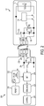
- FIG 2 is a schematic diagram of a mobile terminal 200 which has a battery presence detection system according to an embodiment.
- the mobile terminal 200 is connectable to a battery 101 similar to the battery illustrated in Figure 1 , and described in the background art section above.
- the battery 101 depicts a capacitance 116 Cbat that, in addition to capacitance in the mobile terminal 200, is exploited by the exemplary embodiments to detect presence or absence of the battery 101 as will be described in more detail below.
- This capacitance Cbat 116 may be physically present in the battery 100 of Figure 1 , but is not used by conventional battery presence detectors as part of the system for determining whether the battery is connected to a battery-powered device.
- FIG. 2 three pairs of physical connectors 150 are illustrated, but other pairs of physical connectors may exist. In each pair, one physical connector is on the battery side and another physical connector is on the mobile terminal side.
- the battery presence detection line (BDET) 104, the battery ground line (GND) 106 and the battery cell voltage line (VBAT) 108 in the battery are connected via respective pairs of physical connectors 150 to a corresponding terminal battery presence detection line (BDET) 204, a terminal ground line (GND) 206 and a battery cell voltage line (VBAT) 208 in the mobile terminal 200.
- BDET battery presence detection line
- GND battery ground line
- VBAT battery cell voltage line
- the battery presence detection line (BDET) 104 is connected to the battery ground line 104 via the resistor RID 110 and the capacitance Cbat 116.
- the battery detection line 204 is connected to the terminal ground line 206 via a capacitance Cterm 210.
- the capacitance Cterm 210 may include a parasitic capacitance associated with, for example, surge protection electronics of the mobile terminal or alternatively Cterm 210 may include a discrete capacitor component which is, e.g., used to perform filtering.
- the battery presence detection system inside the mobile terminal 200 includes, according to this exemplary embodiment, a pulse generator 212 that generates a pulse signal applied to the battery detection line (BDET) 204 inside the mobile terminal.
- This pulse signal has the effect of charging the line capacitance to a known value at regular intervals. The manner in which the known charge value is discharged is then monitored to determine whether the battery is connected or not as will now be discussed with respect to Figure 3 .
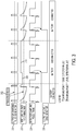
- Figure 3 illustrates exemplary waveforms (i.e., voltage values as a function of time) for voltages related to components of the embodiment of Figure 2 .
- the graph is separated into three time periods: in a first time period the battery is connected to the mobile terminal, in a second (middle) time period the battery is disconnected from the mobile terminal, and in a third (last) time period the battery is again connected to the mobile terminal.
- the pulse signal is, in this exemplary embodiment, periodical, and includes a first time interval during which the pulse signal has a constant high voltage (i.e., a pulse), and a second time interval during which the pulse signal has a low (zero) voltage, in each period.
- the pulse generator may be implemented in hardware, firmware, software or a combination thereof and may generate pulses periodically or irregularly.
- the pulse generator 212 In order to achieve a response time of less than, for example, 500 ⁇ s, the pulse generator 212 generates pulses at an operating frequency of at least a few KHz.
- the operating frequency of the pulse generator 212 can be chosen to be larger than 20 KHz, although this is not a requirement.
- a typical value of the operating frequency may also be chosen based upon the various oscillators which are already available in the battery-powered device in which the battery detection system according to these exemplary embodiments is being implemented, e.g., about 32 KHz in some mobile terminals.
- the capacitance Cterm 210 is charged, and the voltage on the battery detection line 204 is then equal to the high voltage of the applied pulse as seen in graph 302. If the battery 101 is connected to the mobile terminal 200, the capacitance Cbat 116 is also charged because the battery presence detection line (BDET) 104 inside the battery is connected to the battery presence detection line (BDET) 204 inside the terminal.
- BDET battery presence detection line
- Figure 3 illustrates the above-described exponential decrease of the voltage on the battery presence detection line (BDET) 204 inside the terminal while the battery 101 is connected to the mobile terminal.
- BDET battery presence detection line
- the battery detection system according to exemplary embodiments still functions.
- the capacitance 116 Cbat between the battery presence detection line 104 and the battery ground line 106 may include an unavoidable effect of the traces and dielectrics present in the device for other reasons, such as a parasitic capacity related to the surge protection electronics.
- batteries used for mobile terminals typically have an 8 KV galvanic surge protection and a 15 KV battery-to-air protection.
- a capacitance value of the parasitic capacity in either the mobile terminal or the battery is often on the order of tens of pF, frequently about 100 pF, but may be up to 300 pF.
- Either or both of the capacitances Cbat and Cterm may include parasitic capacitance and/or actual, discrete capacitors.
- the capacitance Cterm 210 ceases to discharge and maintains a voltage value as of the moment when the disconnection of the battery from the mobile terminal occurs, until a new pulse is applied.
- the portion 308 of waveform 302. When, after the disconnection, the new pulse is applied, the voltage on the battery presence detection line (BDET) 204 inside the terminal increases to a maximum value, i.e., the applied pulse voltage, which is then maintained since no further discharge occurs as long as the battery is disconnected. This can be seen by the portion 310 of the waveform 302.
- BDET battery presence detection line
- the battery presence detector system illustrated in Figure 2 uses less energy by applying pulse signals and not continuous signals. Moreover, having zero energy consumption at the time of battery disconnect allows more time for the rest of the system to perform a controlled shut down, since the detection system is still running from the charge that is left in VBAT line capacitance and/or other regulator capacitances.
- the battery presence detection system further includes a detector 214 configured to detect features of the voltage on the battery presence detection line (BDET) 204 inside the terminal 200.
- the detector 214 may, for example, be a level detector which detects when the voltage value on the battery presence detection line (BDET) 204 becomes higher than a reference voltage value (i.e., a trigger level 312), which value can be freely selected based upon, for example, the resistance and capacitance values described above associated with the particular device and peripheral of interest and the desired periodicity at which the detection system should check for disconnection.
- the detector 214 may be a rising edge detector which detects a rising voltage edge for the voltage on the battery presence detection line (BDET) 204. Note that in order to detect the rising voltage edge, the voltage must rise above a trigger voltage value.
- the detector 214 may be implemented in hardware, firmware, software or as a combination thereof.
- the detector 214 samples the voltage on the battery presence detection line (BDET) 204 at predetermined times according to, for example, a detector sampling pulse train 304 illustrated as the third (from top to bottom) voltage versus time graph in Figure 3 .
- the sampling points may vary depending on whether the detector 214 is a level detector or a rising edge detector as illustrated in Figure 3 .
- the pulse generator 212 and the detector 214 may be connected so that the pulse signal and the detector sampling pulse train are synchronized.
- the detector 214 outputs an indication that the battery is disconnected. For example, the detector 214 outputs a first voltage value if the line voltage edge or the line voltage level of the voltage on the battery presence detection line (BDET) 204 is detected at a preceding sampling time. Conversely, the detector 214 outputs a second voltage value if the line voltage edge or the line voltage level of the voltage on the battery presence detection line (BDET) 204 is not detected at the preceding sampling time.
- Such an output 306 of the detector 214 is illustrated in the fourth (bottom) voltage versus time graph in Figure 3 .
- the indication output by the detector 214 that the battery is disconnected may be received by a control unit 216 configured to shut down the mobile terminal 200 in a controlled manner.
- the control unit 216 may be implemented in hardware, firmware, software or as a combination thereof.
- the control unit 216 may shut down also the battery presence detection system (i.e., the detector 214 and the pulse generator 212. However if, prior to completing the shutting down of the mobile terminal 200, the battery presence detection system still operating determines that the battery is again connected, the control unit 216 may abort the shutting down of the mobile terminal. Alternatively, once the shut down process is initiated it can be completed regardless of whether the battery presence detection system determines that the battery is again connected during the shut down process.
- the battery presence detection system may further include a remnant power source 218 configured to provide power to the pulse generator 212 and the detector 214 even when the battery becomes disconnected.
- the remnant power source 218 may be a clock signal generating unit.
- the remnant power source 218 may also be a temporary power storage unit or element which stores electrical energy that is slowly discharged after the battery 101 becomes disconnected.
- a good battery presence detection system should be usable with batteries of various types. Different types of batteries may have different resistance values for the resistor RID 110 and different capacitance values for the capacitance Cbat 116.
- the values of the resistance and of the capacitance determine the time constant of the exponential decrease of the voltage on the battery presence detection line (BDET) 204 when the battery 101 is connected.
- BDET battery presence detection line
- the battery presence detection system may further include a battery type adjusting unit (e.g. included in the pulse generator 212) configured to adjust a pulse generator frequency according to values of the resistor RID 110 and the capacitance Cbat 116, thereby, allowing, for example, a longer interval during which the voltage on the battery presence detection line (BDET) 204 decreases.
- a battery type adjusting unit e.g. included in the pulse generator 212 configured to adjust a pulse generator frequency according to values of the resistor RID 110 and the capacitance Cbat 116, thereby, allowing, for example, a longer interval during which the voltage on the battery presence detection line (BDET) 204 decreases.
- BDET battery presence detection line
- the battery presence detection system may further include a battery type adjusting unit (e.g. included in the pulse generator 212) configured to adjust voltage reference levels used by the detector 214 to detect the presence of the line voltage edge or the line voltage level on the terminal battery detection line 204, according to values of the resistor RID 110 and the capacitance Cbat 116.
- a battery type adjusting unit e.g. included in the pulse generator 212 configured to adjust voltage reference levels used by the detector 214 to detect the presence of the line voltage edge or the line voltage level on the terminal battery detection line 204, according to values of the resistor RID 110 and the capacitance Cbat 116.
- the battery presence detection system may also include a digital debounce filter 220 connected to the pulse detector, in order to filter out spurious signals such as minor glitches or noise.
- a digital debounce filter 220 is fault tolerant. If, for example, a 32Khz clock is used in the system and a 500us minimum disconnection time is required to start the shutdown process, then about 16 consecutive missing pulses in the debounce filter 220 should be counted before releasing the shutdown alarm. This purely illustrative example provides a highly fault tolerant technique for determining disconnection of the peripheral device.
- the battery detection system omits the pulse generator 212 (but includes the other elements of Figure 2 ).
- An exemplary smart battery 500 is illustrated in Figure 5 , wherein the elements are the same as those described in Figure 2 for battery 101 except for the inclusion of the smart battery IC 502.
- a clock signal used in the digital communication between the smart battery and the mobile terminal is applied as the pulse signal to charge the terminal battery detection line.
- Digital communications can be performed, for example, between the clock signal pulses applied to the BDET line.
- a flow diagram of a method for detecting whether a battery is connected to a device is illustrated in Figure 4 .
- the method includes applying a pulsed signal to a terminal battery detection line, at S410.
- the method further includes detecting presence of one of a line voltage edge and a line voltage level on the terminal battery detection line, at S420.
- the method also includes determining whether the battery is connected to the device based on the detecting, at S430.
- the method may also include outputting a first voltage value if determined that the battery is connected at a preceding predetermined time, and a second voltage value if determined that the battery is disconnected.
- the method may also include shutting down the device in a controlled manner when the determining concludes that the battery is not connected to the device.
- the method may also include adjusting at least one of a pulse generator frequency of the pulse signal and voltage reference levels used to detect the presence of the one of the line voltage edge and the line voltage level on the terminal detection line, according to values of the pull-down resistor and the battery capacitance.
- the method may also include synchronizing a detector sampling pulse train used to select the predetermined time intervals with the pulse signal.
- the disclosed exemplary embodiments provide a system and a method for detecting battery presence in a device with a reduced consumption of energy and at a low cost. It should be understood that this description is not intended to limit the invention. On the contrary, the exemplary embodiments are intended to cover alternatives, modifications and equivalents, which are included in the spirit and scope of the invention as defined by the appended claims. For example, the afore-described exemplary embodiments could also be used also to detect the presence of peripheral devices other than batteries that have pull-down resistance. Furthermore, there could be alternatively be a pull-up resistor used in peripheral side (instead of a pull-down resistor) and therefore signaling polarities would be reversed but detection could otherwise be performed in the manner described above. Further, in the detailed description of the exemplary embodiments, numerous specific details are set forth in order to provide a comprehensive understanding of the claimed invention. However, one skilled in the art would understand that various embodiments may be practiced without such specific details.
Landscapes
- Engineering & Computer Science (AREA)
- Power Engineering (AREA)
- Physics & Mathematics (AREA)
- General Physics & Mathematics (AREA)
- Nonlinear Science (AREA)
- Charge And Discharge Circuits For Batteries Or The Like (AREA)
- Secondary Cells (AREA)
- Telephone Function (AREA)
Claims (20)
- Batterieanwesenheitsermittlungssystem einer Vorrichtung (200), wobei die Vorrichtung mit einer Batterie (101, 500) verbindbar ist und die Vorrichtung (200) eine Batterieermittlungsleitung (104), eine Batterieerdungsleitung (106) und eine Batteriezellenspannungsleitung (108) aufweist, wobei die Batterieermittlungsleitung (104) der Batterie (101, 500) mit der Batterieerdungsleitung (106) der Batterie (101, 500) über einen Pulldown-Widerstand (110) verbunden ist, wobei das Batterieanwesenheitsermittlungssystem gekennzeichnet ist durch
eine Endgerät-Batterieermittlungsleitung (204), die dazu konfiguriert ist, mit der Batterieermittlungsleitung (104) der Batterie (101, 500) verbunden zu werden, wenn die Batterie (101, 500) mit der Vorrichtung (200) verbunden ist,
eine Endgerät-Erdungsleitung (206), die dazu konfiguriert ist, mit der Batterieerdungsleitung (106) der Batterie (101, 500) verbunden zu werden, wenn die Batterie (101, 500) mit der Vorrichtung (200) verbunden ist,
eine Endgerät-Kapazität (210) zwischen der Endgerät-Batterieermittlungsleitung (204) und der Endgerät-Erdungsleitung (206);
einen Impulsgenerator (212), der dazu konfiguriert ist, ein Netzladeimpulssignal (300) zu erzeugen, das an die Endgerät-Batterieermittlungsleitung (204) angelegt wird; und
einen Detektor (214), der dazu konfiguriert ist, eine Anwesenheit von einem aus einer Netzspannungsflanke und einem Netzspannungspegel an der Endgerät-Batterieermittlungsleitung (204) zu ermitteln, und eine Anzeige darüber auszugeben, ob die Batterie (101, 500) mit der Vorrichtung (200) verbunden ist, basierend auf der Anwesenheit des einen aus der Netzspannungsflanke und dem Netzspannungspegel an der Endgerät-Batterieermittlungsleitung (204). - Batterieanwesenheitsermittlungssystem nach Anspruch 1, des Weiteren umfassend eine Steuereinheit (216), die dazu konfiguriert ist,
die Anzeige von dem Detektor (214) zu empfangen, und
die Vorrichtung (200) auf kontrollierte Weise abzuschalten, wenn die Anzeige ergibt, dass die Batterie (101, 500), nicht mit der Vorrichtung (200) verbunden ist. - Batterieanwesenheitsermittlungssystem nach Anspruch 2, wobei die Steuereinheit (216) dazu konfiguriert ist, den Detektor (214) beim Abschalten der Vorrichtung (200) auf kontrollierte Weise abzuschalten.
- Batterieanwesenheitsermittlungssystem nach Anspruch 1, wobei die Anzeige von dem Detektor (214) ein erster Spannungswert ist, wenn die Netzspannungsflanke oder der Netzspannungspegel der Spannung an der Endgerät-Batterieermittlungsleitung (204) zu einem vorgegebenen Zeitpunkt ermittelt wird, und ein zweiter Spannungswert, wenn die Netzspannungsflanke oder der Netzspannungspegel der Spannung an der Endgerät-Batterieermittlungsleitung (204) nicht zu dem vorgegebenen Zeitpunkt ermittelt wird.
- Batterieanwesenheitsermittlungssystem nach Anspruch 1, wobei der Detektor (214) ein Pegeldetektor ist, der zum Ermitteln eingerichtet ist, um eine Spannung an der Endgerät-Batterieermittlungsleitung (204) größer als ein vorgegebener Pegel wird.
- Batterieanwesenheitsermittlungssystem nach Anspruch 1, wobei der Detektor (214) ein Detektor für ansteigende Flanken ist, der zum Bestimmen eingerichtet ist, ob eine ansteigende Flanke einer Spannung der Endgerät-Batterieermittlungsleitung (204) vorhanden ist.
- Batterieanwesenheitsermittlungssystem nach Anspruch 1, umfassend eine Reststromquelle (218), die dazu eingerichtet ist, Strom für den Impulsgenerator (212) zu liefern, wenn die Batterie (101, 500) getrennt wird.
- Batterieanwesenheitsermittlungssystem nach Anspruch 7, wobei die Reststromquelle (218) eine Taktsignal-Erzeugungseinheit ist.
- Batterieanwesenheitsermittlungssystem nach Anspruch 7, wobei die Reststromquelle (218) eine temporäre Stromspeichereinheit ist, die entladen wird, nachdem die Batterie (101, 500) getrennt wurde.
- Batterieanwesenheitsermittlungssystem nach Anspruch 1, wobei ein Zeitintervall zwischen dem Zeitpunkt, an dem die Batterie (101, 500) getrennt wird, und dem Zeitpunkt, an dem der Detektor die Anzeige ausgibt, dass die Batterie (101, 500) getrennt wurde, weniger als 500 µs beträgt.
- Batterieanwesenheitsermittlungssystem nach Anspruch 10, wobei der Impulsgenerator (212) bei einer Frequenz von mindestens 20 kHz arbeitet.
- Batterieanwesenheitsermittlungssystem nach Anspruch 1, umfassend eine Batterietyp-Anpassungseinheit, die mindestens eines aus einer Impulsgeneratorfrequenz und Spannungreferenzpegeln, die von dem Detektor (214) zur Ermittlung der Anwesenheit des einen aus der Netzspannungsflanke und dem Netzspannungspegel verwendet werden, entsprechend Werten des Pulldown-Widerstands (110) und einer Kapazität (116) der Batterie (101, 500) zwischen der Endgerät-Batterieermittlungsleitung (204) und der Endgerät-Erdungsleitung (206) anpasst, wenn die Batterie (101, 500) angeschlossen ist.
- Batterieanwesenheitsermittlungssystem nach Anspruch 1, wobei der Impulsgenerator (212) mit dem Detektor (214) verbunden ist, um es zu ermöglichen, dass der Detektor (214) eine Detektor-Abtastimpulskette (304), die zum Auswählen der vorgegebenen Zeiten in dem Detektor (214) verwendet wird, mit dem Impulssignal (300) synchronisiert.
- Batterieanwesenheitsermittlungssystem nach Anspruch 1, umfassend einen digitalen Entprellfilter (220), der mit einem Ausgang des Detektors (214) verbunden ist.
- Vorrichtung (200) umfassend ein Batterieanwesenheitsermittlungssystem nach einem der Ansprüche 1 bis 14.
- Vorrichtung (200) nach Anspruch 15, wobei es sich um ein mobiles Endgerät handelt.
- Verfahren zum Ermitteln, ob eine Batterie (101, 500) mit einer Vorrichtung (200) verbunden ist, durch eine Endgerät-Batterieermittlungsleitung (204) der Vorrichtung (200) mit einer Endgerät-Batterieermittlungsleitung (104) der Batterie (101, 500), eine Endgerät-Erdungsleitung (206) der Vorrichtung (200) mit einer Endgerät-Erdungsleitung (106) der Batterie (101, 500) und eine Batteriezellenspannungsleitung (208) der Vorrichtung (200) mit einer Batteriezellenspannungsleitung (108) der Batterie (101, 500), wobei das Verfahren umfasst:Anlegen (S410) eines Netzladeimpulssignals (300) an die Endgerät-Batterieermittlungsleitung (204), die mit der Erdungsleitung (206) über einen Pulldown-Widerstand (110) und eine Kapazität (116) verbunden ist, während die Batterie (101, 500) mit der Vorrichtung (200) verbunden ist;Ermitteln (S420), ob eines aus einer Netzspannungsflanke und einem Netzspannungspegel einer Spannung an der Endgerät-Batterieermittlungsleitung (204) vorhanden ist; undBestimmen (S430), ob die Batterie (101, 500) mit der Vorrichtung (200 verbunden ist, basierend auf der Ermittlung.
- Verfahren nach Anspruch 17, des Weiteren umfassend:Ausgeben eines ersten Spannungswertes, wenn bestimmt wird, dass die Batterie (101, 500) mit der Vorrichtung (200) verbunden ist, und eines zweiten Spannungswertes, wenn bestimmt wird, dass die Batterie (101, 500) von der Vorrichtung (200) getrennt ist.
- Verfahren nach Anspruch 16, des Weiteren umfassend:Abschalten der Vorrichtung (200) auf kontrollierte Weise, wenn die Bestimmung ergibt, dass die Batterie (101, 500), nicht mit der Vorrichtung (200) verbunden ist.
- Verfahren nach Anspruch 17, des Weiteren umfassend:Anpassen von mindestens einem aus einer Impulsgeneratorfrequenz des Impulssignals (300) und aus Spannungsreferenzpegeln, die zum Ermitteln verwendet werden, ob das eine aus der Netzspannungsflanke und dem Netzspannungspegel an der Endgerät-Batterieermittlungsleitung (204) vorhanden ist, entsprechend Werten des Pulldown-Widerstands (110) und der Kapazität (116).
Applications Claiming Priority (2)
| Application Number | Priority Date | Filing Date | Title |
|---|---|---|---|
| US12/767,986 US8604748B2 (en) | 2010-04-27 | 2010-04-27 | Methods and systems for detecting battery presence |
| PCT/EP2011/055684 WO2011134781A2 (en) | 2010-04-27 | 2011-04-12 | Methods and systems for detecting battery presence |
Publications (2)
| Publication Number | Publication Date |
|---|---|
| EP2564485A2 EP2564485A2 (de) | 2013-03-06 |
| EP2564485B1 true EP2564485B1 (de) | 2017-10-11 |
Family
ID=44625896
Family Applications (1)
| Application Number | Title | Priority Date | Filing Date |
|---|---|---|---|
| EP11714965.8A Not-in-force EP2564485B1 (de) | 2010-04-27 | 2011-04-12 | Detektionsverfahren und -systeme für das vorhandensein einer batterie |
Country Status (3)
| Country | Link |
|---|---|
| US (1) | US8604748B2 (de) |
| EP (1) | EP2564485B1 (de) |
| WO (1) | WO2011134781A2 (de) |
Families Citing this family (16)
| Publication number | Priority date | Publication date | Assignee | Title |
|---|---|---|---|---|
| BRPI1010083A2 (pt) * | 2009-06-22 | 2016-03-15 | Koninkl Philips Electronics Nv | unidade de alimetação para alimentar um dispositivo operado eletricamente com energia elétrica e/ou sinal elétrico por meio de elementos conectores para um contato liberável de meios conectoresdedicados do dispositivo operado eletricamente, dispositivo operado eletricamente para cooperar com a unidade de alimentação, sistema elétrico e método para alimentar um dispositivo operado eletricamente com energia elétrica e/ou sinal elétrico por meio de elementos conctores para um contato liberável de meios conectores dedicados do dispositivo operado eletricamente |
| CA2802011A1 (en) * | 2010-06-11 | 2011-12-15 | Nokia Corporation | Method for battery removal detection |
| US9172120B2 (en) * | 2010-07-14 | 2015-10-27 | Sinoelectric Powertrain Corporation | Battery pack fault communication and handling |
| US8700934B2 (en) * | 2010-07-27 | 2014-04-15 | Blackberry Limited | System and method for dynamically configuring processing speeds in a wireless mobile telecommunications device |
| US9825475B2 (en) * | 2011-04-28 | 2017-11-21 | Zoll Circulation, Inc. | System and method for automated detection of battery insert |
| CN103797681B (zh) | 2011-04-28 | 2018-05-11 | 佐尔循环公司 | 跟踪并存档电池性能数据的系统和方法 |
| CN107257152B (zh) | 2011-04-28 | 2021-04-09 | 佐尔循环公司 | 用于更新数据、操作参数和/或软件的系统 |
| DE102011086060A1 (de) * | 2011-11-10 | 2013-05-16 | Sb Limotive Company Ltd. | Verfahren zur sicherheitsbedingten Abschaltung eines elektrischen Netzes und Sicherheitseinrichtung |
| DE102011089145A1 (de) * | 2011-12-20 | 2013-06-20 | Robert Bosch Gmbh | Schutzvorrichtung, Verfahren und Energieversorgungssystem |
| US20140143588A1 (en) * | 2012-11-21 | 2014-05-22 | Nokia Corporation | Instant Communication Error Indication From Slave |
| CN103545882B (zh) * | 2013-10-11 | 2015-07-22 | 华为技术有限公司 | 电池在位检测方法、装置及充电系统 |
| DE102014116800A1 (de) | 2014-11-17 | 2016-05-19 | Knorr-Bremse Systeme für Nutzfahrzeuge GmbH | Verfahren zur Erkennung einer Batterie sowie Spannungsversorgungssystem |
| US9897661B2 (en) | 2015-03-17 | 2018-02-20 | Microsoft Technology Licensing, Llc | Automatically determining a number of functioning batteries |
| CN109672249A (zh) * | 2019-01-22 | 2019-04-23 | 深圳流量链科技有限公司 | 一种电池管理保护装置 |
| US11777150B2 (en) | 2019-08-28 | 2023-10-03 | SparkCharge, Inc. | Battery module |
| DE102020209760A1 (de) | 2020-08-03 | 2022-02-03 | Fronius International Gmbh | Batterieladegerät |
Citations (2)
| Publication number | Priority date | Publication date | Assignee | Title |
|---|---|---|---|---|
| US20050075806A1 (en) * | 2003-10-01 | 2005-04-07 | General Electric Company | Method and system for testing battery connectivity |
| EP1523082A1 (de) * | 2003-10-08 | 2005-04-13 | BLACK & DECKER INC. | Batterieladegerät mit Anwesenheitsbestimmung der Batterie |
Family Cites Families (10)
| Publication number | Priority date | Publication date | Assignee | Title |
|---|---|---|---|---|
| JP2500088B2 (ja) | 1992-10-29 | 1996-05-29 | 日本電気株式会社 | 電池有無検出装置 |
| CN1119054A (zh) * | 1993-03-05 | 1996-03-20 | 摩托罗拉公司 | 具有存储器的存储充电过程的电池 |
| DE69840469D1 (de) | 1997-05-23 | 2009-03-05 | Sony Corp | Elektronisches gerät mit batteriesatz und mitteln zur detektion der batterieankopplung |
| US6340876B1 (en) * | 2000-09-18 | 2002-01-22 | Texas Instruments Incorporated | Method for detecting battery removal or absent battery condition in a constant current charger |
| US6822425B2 (en) * | 2002-01-25 | 2004-11-23 | Vector Products, Inc. | High frequency battery charger and method of operating same |
| JP4842531B2 (ja) | 2003-10-07 | 2011-12-21 | エーケージー アコースティックス ゲーエムベーハー | バッテリー駆動デバイス |
| JP4819037B2 (ja) * | 2004-05-04 | 2011-11-16 | オーツー マイクロ, インコーポレーテッド | 工具識別回路を備えるコードレス電動工具 |
| US7541776B2 (en) * | 2004-12-10 | 2009-06-02 | Apple Inc. | Method and system for operating a portable electronic device in a power-limited manner |
| KR100876776B1 (ko) * | 2007-04-17 | 2009-01-09 | 삼성전자주식회사 | 통신 시스템에서 gps 정보를 이용한 시간 동기화 방법및 장치 |
| US7755321B2 (en) | 2008-03-13 | 2010-07-13 | Sony Ericsson Mobile Communications Ab | Method and apparatus for battery removal detection |
-
2010
- 2010-04-27 US US12/767,986 patent/US8604748B2/en active Active
-
2011
- 2011-04-12 EP EP11714965.8A patent/EP2564485B1/de not_active Not-in-force
- 2011-04-12 WO PCT/EP2011/055684 patent/WO2011134781A2/en not_active Ceased
Patent Citations (2)
| Publication number | Priority date | Publication date | Assignee | Title |
|---|---|---|---|---|
| US20050075806A1 (en) * | 2003-10-01 | 2005-04-07 | General Electric Company | Method and system for testing battery connectivity |
| EP1523082A1 (de) * | 2003-10-08 | 2005-04-13 | BLACK & DECKER INC. | Batterieladegerät mit Anwesenheitsbestimmung der Batterie |
Also Published As
| Publication number | Publication date |
|---|---|
| US8604748B2 (en) | 2013-12-10 |
| EP2564485A2 (de) | 2013-03-06 |
| WO2011134781A3 (en) | 2012-07-05 |
| WO2011134781A2 (en) | 2011-11-03 |
| US20110260755A1 (en) | 2011-10-27 |
Similar Documents
| Publication | Publication Date | Title |
|---|---|---|
| EP2564485B1 (de) | Detektionsverfahren und -systeme für das vorhandensein einer batterie | |
| EP3327892B1 (de) | Lade- und entladesteuerschaltung und batteriepack | |
| US9673643B2 (en) | Battery presence detecting method, apparatus and charging system | |
| CN103703604B (zh) | 具有简化的监管的蓄电池的电池组的系统 | |
| CN109642919B (zh) | 接地检测装置以及蓄电系统 | |
| US9118202B2 (en) | Battery status detection method and apparatus for electronic device | |
| CN107167690B (zh) | 一种电池组电压采集系统断线检测装置和方法 | |
| CN106904091B (zh) | 一种电池充电方法、系统和车身控制器 | |
| EP4084311B1 (de) | Aufwachschaltung für laderegler, bordladegerät und fahrzeuge mit neuer energie | |
| CN102313873B (zh) | 电池节数检测电路及方法和监测系统 | |
| CN108732448A (zh) | 电池管理系统中的断线检测方法及断线解除检测方法 | |
| KR20090057876A (ko) | 배터리팩의 잔류용량 측정의 수정장치와 방법 | |
| CN102195299A (zh) | 电池充电系统及方法 | |
| CN108957196B (zh) | 一种电池包接入检测电路、方法及充电装置 | |
| EP2365602B1 (de) | Batteriepackladegerät | |
| EP4235196A1 (de) | Schaltererkennungsschaltung, verfahren und schalterdetektor | |
| CN105375544A (zh) | 一种低电量电池充电方法及电源管理集成电路 | |
| CN113541250B (zh) | 电池充电控制电路及电子设备 | |
| US7847516B2 (en) | Circuit and method for detecting absent battery condition in a linear charger | |
| CN109283445B (zh) | 一种储能式轨道车辆充电系统的绝缘检测方法及控制器 | |
| EP3521094B1 (de) | Verfahren und vorrichtung zum erhalten von innenseitigen, aussenseitigen isolationswiderständen eines relais und batteriemanagementsystem | |
| KR102471293B1 (ko) | 다수의 유사한 직렬 배터리 셀 모듈 간의 데이터 교환을 위한 통신 장치를 구비한 배터리 셀 모듈 | |
| CN105958569A (zh) | 脉冲充电方法、脉冲充电管理芯片及电池系统 | |
| US20090027003A1 (en) | Safety Circuit For Charging Devices | |
| US20180145524A1 (en) | Battery charging circuit and charging method thereof |
Legal Events
| Date | Code | Title | Description |
|---|---|---|---|
| PUAI | Public reference made under article 153(3) epc to a published international application that has entered the european phase |
Free format text: ORIGINAL CODE: 0009012 |
|
| 17P | Request for examination filed |
Effective date: 20121127 |
|
| AK | Designated contracting states |
Kind code of ref document: A2 Designated state(s): AL AT BE BG CH CY CZ DE DK EE ES FI FR GB GR HR HU IE IS IT LI LT LU LV MC MK MT NL NO PL PT RO RS SE SI SK SM TR |
|
| DAX | Request for extension of the european patent (deleted) | ||
| 17Q | First examination report despatched |
Effective date: 20150401 |
|
| RAP1 | Party data changed (applicant data changed or rights of an application transferred) |
Owner name: OCT CIRCUIT TECHNOLOGIES INTERNATIONAL LIMITED |
|
| REG | Reference to a national code |
Ref country code: DE Ref legal event code: R079 Ref document number: 602011042282 Country of ref document: DE Free format text: PREVIOUS MAIN CLASS: H02J0007000000 Ipc: H03K0005153000 |
|
| GRAP | Despatch of communication of intention to grant a patent |
Free format text: ORIGINAL CODE: EPIDOSNIGR1 |
|
| RIC1 | Information provided on ipc code assigned before grant |
Ipc: H03K 5/153 20060101AFI20170314BHEP Ipc: G01R 31/02 20060101ALI20170314BHEP Ipc: H02J 7/00 20060101ALI20170314BHEP |
|
| INTG | Intention to grant announced |
Effective date: 20170420 |
|
| GRAS | Grant fee paid |
Free format text: ORIGINAL CODE: EPIDOSNIGR3 |
|
| GRAA | (expected) grant |
Free format text: ORIGINAL CODE: 0009210 |
|
| AK | Designated contracting states |
Kind code of ref document: B1 Designated state(s): AL AT BE BG CH CY CZ DE DK EE ES FI FR GB GR HR HU IE IS IT LI LT LU LV MC MK MT NL NO PL PT RO RS SE SI SK SM TR |
|
| REG | Reference to a national code |
Ref country code: GB Ref legal event code: FG4D |
|
| REG | Reference to a national code |
Ref country code: CH Ref legal event code: EP |
|
| REG | Reference to a national code |
Ref country code: IE Ref legal event code: FG4D |
|
| REG | Reference to a national code |
Ref country code: AT Ref legal event code: REF Ref document number: 936857 Country of ref document: AT Kind code of ref document: T Effective date: 20171115 |
|
| REG | Reference to a national code |
Ref country code: DE Ref legal event code: R096 Ref document number: 602011042282 Country of ref document: DE |
|
| REG | Reference to a national code |
Ref country code: NL Ref legal event code: MP Effective date: 20171011 |
|
| REG | Reference to a national code |
Ref country code: LT Ref legal event code: MG4D |
|
| REG | Reference to a national code |
Ref country code: AT Ref legal event code: MK05 Ref document number: 936857 Country of ref document: AT Kind code of ref document: T Effective date: 20171011 |
|
| PG25 | Lapsed in a contracting state [announced via postgrant information from national office to epo] |
Ref country code: NL Free format text: LAPSE BECAUSE OF FAILURE TO SUBMIT A TRANSLATION OF THE DESCRIPTION OR TO PAY THE FEE WITHIN THE PRESCRIBED TIME-LIMIT Effective date: 20171011 |
|
| PG25 | Lapsed in a contracting state [announced via postgrant information from national office to epo] |
Ref country code: LT Free format text: LAPSE BECAUSE OF FAILURE TO SUBMIT A TRANSLATION OF THE DESCRIPTION OR TO PAY THE FEE WITHIN THE PRESCRIBED TIME-LIMIT Effective date: 20171011 Ref country code: SE Free format text: LAPSE BECAUSE OF FAILURE TO SUBMIT A TRANSLATION OF THE DESCRIPTION OR TO PAY THE FEE WITHIN THE PRESCRIBED TIME-LIMIT Effective date: 20171011 Ref country code: FI Free format text: LAPSE BECAUSE OF FAILURE TO SUBMIT A TRANSLATION OF THE DESCRIPTION OR TO PAY THE FEE WITHIN THE PRESCRIBED TIME-LIMIT Effective date: 20171011 Ref country code: ES Free format text: LAPSE BECAUSE OF FAILURE TO SUBMIT A TRANSLATION OF THE DESCRIPTION OR TO PAY THE FEE WITHIN THE PRESCRIBED TIME-LIMIT Effective date: 20171011 Ref country code: NO Free format text: LAPSE BECAUSE OF FAILURE TO SUBMIT A TRANSLATION OF THE DESCRIPTION OR TO PAY THE FEE WITHIN THE PRESCRIBED TIME-LIMIT Effective date: 20180111 |
|
| PG25 | Lapsed in a contracting state [announced via postgrant information from national office to epo] |
Ref country code: RS Free format text: LAPSE BECAUSE OF FAILURE TO SUBMIT A TRANSLATION OF THE DESCRIPTION OR TO PAY THE FEE WITHIN THE PRESCRIBED TIME-LIMIT Effective date: 20171011 Ref country code: HR Free format text: LAPSE BECAUSE OF FAILURE TO SUBMIT A TRANSLATION OF THE DESCRIPTION OR TO PAY THE FEE WITHIN THE PRESCRIBED TIME-LIMIT Effective date: 20171011 Ref country code: IS Free format text: LAPSE BECAUSE OF FAILURE TO SUBMIT A TRANSLATION OF THE DESCRIPTION OR TO PAY THE FEE WITHIN THE PRESCRIBED TIME-LIMIT Effective date: 20180211 Ref country code: GR Free format text: LAPSE BECAUSE OF FAILURE TO SUBMIT A TRANSLATION OF THE DESCRIPTION OR TO PAY THE FEE WITHIN THE PRESCRIBED TIME-LIMIT Effective date: 20180112 Ref country code: AT Free format text: LAPSE BECAUSE OF FAILURE TO SUBMIT A TRANSLATION OF THE DESCRIPTION OR TO PAY THE FEE WITHIN THE PRESCRIBED TIME-LIMIT Effective date: 20171011 Ref country code: LV Free format text: LAPSE BECAUSE OF FAILURE TO SUBMIT A TRANSLATION OF THE DESCRIPTION OR TO PAY THE FEE WITHIN THE PRESCRIBED TIME-LIMIT Effective date: 20171011 Ref country code: BG Free format text: LAPSE BECAUSE OF FAILURE TO SUBMIT A TRANSLATION OF THE DESCRIPTION OR TO PAY THE FEE WITHIN THE PRESCRIBED TIME-LIMIT Effective date: 20180111 |
|
| REG | Reference to a national code |
Ref country code: DE Ref legal event code: R097 Ref document number: 602011042282 Country of ref document: DE |
|
| PG25 | Lapsed in a contracting state [announced via postgrant information from national office to epo] |
Ref country code: DK Free format text: LAPSE BECAUSE OF FAILURE TO SUBMIT A TRANSLATION OF THE DESCRIPTION OR TO PAY THE FEE WITHIN THE PRESCRIBED TIME-LIMIT Effective date: 20171011 Ref country code: EE Free format text: LAPSE BECAUSE OF FAILURE TO SUBMIT A TRANSLATION OF THE DESCRIPTION OR TO PAY THE FEE WITHIN THE PRESCRIBED TIME-LIMIT Effective date: 20171011 Ref country code: SK Free format text: LAPSE BECAUSE OF FAILURE TO SUBMIT A TRANSLATION OF THE DESCRIPTION OR TO PAY THE FEE WITHIN THE PRESCRIBED TIME-LIMIT Effective date: 20171011 Ref country code: CZ Free format text: LAPSE BECAUSE OF FAILURE TO SUBMIT A TRANSLATION OF THE DESCRIPTION OR TO PAY THE FEE WITHIN THE PRESCRIBED TIME-LIMIT Effective date: 20171011 |
|
| PLBE | No opposition filed within time limit |
Free format text: ORIGINAL CODE: 0009261 |
|
| STAA | Information on the status of an ep patent application or granted ep patent |
Free format text: STATUS: NO OPPOSITION FILED WITHIN TIME LIMIT |
|
| PG25 | Lapsed in a contracting state [announced via postgrant information from national office to epo] |
Ref country code: SM Free format text: LAPSE BECAUSE OF FAILURE TO SUBMIT A TRANSLATION OF THE DESCRIPTION OR TO PAY THE FEE WITHIN THE PRESCRIBED TIME-LIMIT Effective date: 20171011 Ref country code: IT Free format text: LAPSE BECAUSE OF FAILURE TO SUBMIT A TRANSLATION OF THE DESCRIPTION OR TO PAY THE FEE WITHIN THE PRESCRIBED TIME-LIMIT Effective date: 20171011 Ref country code: RO Free format text: LAPSE BECAUSE OF FAILURE TO SUBMIT A TRANSLATION OF THE DESCRIPTION OR TO PAY THE FEE WITHIN THE PRESCRIBED TIME-LIMIT Effective date: 20171011 Ref country code: PL Free format text: LAPSE BECAUSE OF FAILURE TO SUBMIT A TRANSLATION OF THE DESCRIPTION OR TO PAY THE FEE WITHIN THE PRESCRIBED TIME-LIMIT Effective date: 20171011 |
|
| 26N | No opposition filed |
Effective date: 20180712 |
|
| REG | Reference to a national code |
Ref country code: DE Ref legal event code: R119 Ref document number: 602011042282 Country of ref document: DE |
|
| PG25 | Lapsed in a contracting state [announced via postgrant information from national office to epo] |
Ref country code: MC Free format text: LAPSE BECAUSE OF FAILURE TO SUBMIT A TRANSLATION OF THE DESCRIPTION OR TO PAY THE FEE WITHIN THE PRESCRIBED TIME-LIMIT Effective date: 20171011 Ref country code: SI Free format text: LAPSE BECAUSE OF FAILURE TO SUBMIT A TRANSLATION OF THE DESCRIPTION OR TO PAY THE FEE WITHIN THE PRESCRIBED TIME-LIMIT Effective date: 20171011 |
|
| REG | Reference to a national code |
Ref country code: CH Ref legal event code: PL |
|
| REG | Reference to a national code |
Ref country code: BE Ref legal event code: MM Effective date: 20180430 |
|
| GBPC | Gb: european patent ceased through non-payment of renewal fee |
Effective date: 20180412 |
|
| REG | Reference to a national code |
Ref country code: IE Ref legal event code: MM4A |
|
| PG25 | Lapsed in a contracting state [announced via postgrant information from national office to epo] |
Ref country code: DE Free format text: LAPSE BECAUSE OF NON-PAYMENT OF DUE FEES Effective date: 20181101 Ref country code: LU Free format text: LAPSE BECAUSE OF NON-PAYMENT OF DUE FEES Effective date: 20180412 |
|
| PG25 | Lapsed in a contracting state [announced via postgrant information from national office to epo] |
Ref country code: BE Free format text: LAPSE BECAUSE OF NON-PAYMENT OF DUE FEES Effective date: 20180430 Ref country code: GB Free format text: LAPSE BECAUSE OF NON-PAYMENT OF DUE FEES Effective date: 20180412 Ref country code: LI Free format text: LAPSE BECAUSE OF NON-PAYMENT OF DUE FEES Effective date: 20180430 Ref country code: CH Free format text: LAPSE BECAUSE OF NON-PAYMENT OF DUE FEES Effective date: 20180430 |
|
| PG25 | Lapsed in a contracting state [announced via postgrant information from national office to epo] |
Ref country code: FR Free format text: LAPSE BECAUSE OF NON-PAYMENT OF DUE FEES Effective date: 20180430 Ref country code: IE Free format text: LAPSE BECAUSE OF NON-PAYMENT OF DUE FEES Effective date: 20180412 |
|
| PG25 | Lapsed in a contracting state [announced via postgrant information from national office to epo] |
Ref country code: MT Free format text: LAPSE BECAUSE OF NON-PAYMENT OF DUE FEES Effective date: 20180412 |
|
| PG25 | Lapsed in a contracting state [announced via postgrant information from national office to epo] |
Ref country code: TR Free format text: LAPSE BECAUSE OF FAILURE TO SUBMIT A TRANSLATION OF THE DESCRIPTION OR TO PAY THE FEE WITHIN THE PRESCRIBED TIME-LIMIT Effective date: 20171011 |
|
| PG25 | Lapsed in a contracting state [announced via postgrant information from national office to epo] |
Ref country code: PT Free format text: LAPSE BECAUSE OF FAILURE TO SUBMIT A TRANSLATION OF THE DESCRIPTION OR TO PAY THE FEE WITHIN THE PRESCRIBED TIME-LIMIT Effective date: 20171011 Ref country code: HU Free format text: LAPSE BECAUSE OF FAILURE TO SUBMIT A TRANSLATION OF THE DESCRIPTION OR TO PAY THE FEE WITHIN THE PRESCRIBED TIME-LIMIT; INVALID AB INITIO Effective date: 20110412 |
|
| PG25 | Lapsed in a contracting state [announced via postgrant information from national office to epo] |
Ref country code: MK Free format text: LAPSE BECAUSE OF NON-PAYMENT OF DUE FEES Effective date: 20171011 Ref country code: CY Free format text: LAPSE BECAUSE OF FAILURE TO SUBMIT A TRANSLATION OF THE DESCRIPTION OR TO PAY THE FEE WITHIN THE PRESCRIBED TIME-LIMIT Effective date: 20171011 |
|
| PG25 | Lapsed in a contracting state [announced via postgrant information from national office to epo] |
Ref country code: AL Free format text: LAPSE BECAUSE OF FAILURE TO SUBMIT A TRANSLATION OF THE DESCRIPTION OR TO PAY THE FEE WITHIN THE PRESCRIBED TIME-LIMIT Effective date: 20171011 |