EP2564899A1 - Appareil médical et son procédé de commande - Google Patents
Appareil médical et son procédé de commande Download PDFInfo
- Publication number
- EP2564899A1 EP2564899A1 EP12180093A EP12180093A EP2564899A1 EP 2564899 A1 EP2564899 A1 EP 2564899A1 EP 12180093 A EP12180093 A EP 12180093A EP 12180093 A EP12180093 A EP 12180093A EP 2564899 A1 EP2564899 A1 EP 2564899A1
- Authority
- EP
- European Patent Office
- Prior art keywords
- ultrasound transducer
- ultrasound
- groups
- transducer elements
- signals
- Prior art date
- Legal status (The legal status is an assumption and is not a legal conclusion. Google has not performed a legal analysis and makes no representation as to the accuracy of the status listed.)
- Granted
Links
Images


Classifications
-
- A—HUMAN NECESSITIES
- A61—MEDICAL OR VETERINARY SCIENCE; HYGIENE
- A61N—ELECTROTHERAPY; MAGNETOTHERAPY; RADIATION THERAPY; ULTRASOUND THERAPY
- A61N7/00—Ultrasound therapy
-
- G—PHYSICS
- G10—MUSICAL INSTRUMENTS; ACOUSTICS
- G10K—SOUND-PRODUCING DEVICES; METHODS OR DEVICES FOR PROTECTING AGAINST, OR FOR DAMPING, NOISE OR OTHER ACOUSTIC WAVES IN GENERAL; ACOUSTICS NOT OTHERWISE PROVIDED FOR
- G10K11/00—Methods or devices for transmitting, conducting or directing sound in general; Methods or devices for protecting against, or for damping, noise or other acoustic waves in general
- G10K11/18—Methods or devices for transmitting, conducting or directing sound
- G10K11/26—Sound-focusing or directing, e.g. scanning
- G10K11/34—Sound-focusing or directing, e.g. scanning using electrical steering of transducer arrays, e.g. beam steering
- G10K11/341—Circuits therefor
- G10K11/346—Circuits therefor using phase variation
-
- A—HUMAN NECESSITIES
- A61—MEDICAL OR VETERINARY SCIENCE; HYGIENE
- A61B—DIAGNOSIS; SURGERY; IDENTIFICATION
- A61B18/00—Surgical instruments, devices or methods for transferring non-mechanical forms of energy to or from the body
-
- A—HUMAN NECESSITIES
- A61—MEDICAL OR VETERINARY SCIENCE; HYGIENE
- A61B—DIAGNOSIS; SURGERY; IDENTIFICATION
- A61B8/00—Diagnosis using ultrasonic, sonic or infrasonic waves
- A61B8/44—Constructional features of the ultrasonic, sonic or infrasonic diagnostic device
- A61B8/4483—Constructional features of the ultrasonic, sonic or infrasonic diagnostic device characterised by features of the ultrasound transducer
- A61B8/4494—Constructional features of the ultrasonic, sonic or infrasonic diagnostic device characterised by features of the ultrasound transducer characterised by the arrangement of the transducer elements
-
- A—HUMAN NECESSITIES
- A61—MEDICAL OR VETERINARY SCIENCE; HYGIENE
- A61N—ELECTROTHERAPY; MAGNETOTHERAPY; RADIATION THERAPY; ULTRASOUND THERAPY
- A61N7/00—Ultrasound therapy
- A61N7/02—Localised ultrasound hyperthermia
-
- A—HUMAN NECESSITIES
- A61—MEDICAL OR VETERINARY SCIENCE; HYGIENE
- A61B—DIAGNOSIS; SURGERY; IDENTIFICATION
- A61B8/00—Diagnosis using ultrasonic, sonic or infrasonic waves
- A61B8/08—Clinical applications
-
- A—HUMAN NECESSITIES
- A61—MEDICAL OR VETERINARY SCIENCE; HYGIENE
- A61N—ELECTROTHERAPY; MAGNETOTHERAPY; RADIATION THERAPY; ULTRASOUND THERAPY
- A61N7/00—Ultrasound therapy
- A61N2007/0052—Ultrasound therapy using the same transducer for therapy and imaging
-
- A—HUMAN NECESSITIES
- A61—MEDICAL OR VETERINARY SCIENCE; HYGIENE
- A61N—ELECTROTHERAPY; MAGNETOTHERAPY; RADIATION THERAPY; ULTRASOUND THERAPY
- A61N7/00—Ultrasound therapy
- A61N2007/0056—Beam shaping elements
- A61N2007/0065—Concave transducers
-
- A—HUMAN NECESSITIES
- A61—MEDICAL OR VETERINARY SCIENCE; HYGIENE
- A61N—ELECTROTHERAPY; MAGNETOTHERAPY; RADIATION THERAPY; ULTRASOUND THERAPY
- A61N7/00—Ultrasound therapy
- A61N2007/0086—Beam steering
- A61N2007/0095—Beam steering by modifying an excitation signal
-
- A—HUMAN NECESSITIES
- A61—MEDICAL OR VETERINARY SCIENCE; HYGIENE
- A61N—ELECTROTHERAPY; MAGNETOTHERAPY; RADIATION THERAPY; ULTRASOUND THERAPY
- A61N7/00—Ultrasound therapy
- A61N7/02—Localised ultrasound hyperthermia
- A61N2007/027—Localised ultrasound hyperthermia with multiple foci created simultaneously
Definitions
- the following description relates to a medical apparatus and a method of controlling a medical apparatus.
- HIFU high intensity focused ultrasound
- An intensity of the ultrasound used in the HIFU treatment is about a hundred thousand times greater than an intensity of ultrasound used for diagnosis.
- the ultrasound of the HIFU treatment is focused on and irradiated onto a lesion part to be treated, thereby causing focal destruction or necrosis of the lesion tissue. That is, energy of the ultrasound is focused on and irradiated onto a part of the lesion tissue of the human body and is transformed into thermal energy, thereby causing a temperature of the irradiated part to rise and resulting in coaguable necrosis of the lesion tissue.
- the temperature of the irradiated part rises instantaneously, heat may be prevented from being dispersed into a periphery of the irradiated part. As a result, only the irradiated part of the lesion tissue may be efficiently removed.
- An apparatus utilizing the HIFU treatment uses a transducer that generates and irradiates ultrasound for treatment in response to an electrical signal.
- a multielement ultrasound transducer may be used to achieve the effect of the HIFU treatment.
- a unit generating the input signals should have the same number of output channels as the number of elements of the multielement ultrasound transducer. Therefore, as ultrasound transducer elements are added to a HIFU treatment system, a method by which a signal of each transducer element may be controlled is subject to increased complexity.
- a medical apparatus in one general aspect, includes an ultrasound transducer unit including a plurality of ultrasound transducer elements, the ultrasound transducer elements being configured to transform signals into ultrasound and output the transformed ultrasound, a grouping unit configured to group the ultrasound transducer elements into a plurality of groups, and a signal generating unit configured to generate the signals to be transformed into the ultrasound and output the generated signals to the groups via a plurality of output channels respectively corresponding to the groups.
- the medical apparatus may include that the signal generating unit is further configured to output one or more common signals of the signals to be transformed into the ultrasound via one or more of the output channels, respectively, to respective ones of the groups comprising two or more of the ultrasound transducer elements.
- the medical apparatus may include a channel selection unit configured to select two or more of the output channels via which the signals to be transformed into the ultrasound are to be output to the groups.
- the medical apparatus may include a user interface configured to receive grouping information specifying a quantity of the groups in which the ultrasound transducer elements are to be grouped.
- the channel selection unit is further configured to select the two or more of the output channels according to the received grouping information.
- the medical apparatus may include that the grouping unit is further configured to group the ultrasound transducer elements into activated ultrasound transducer elements and deactivated ultrasound transducer elements, and group the activated ultrasound transducer elements into two or more groups.
- the medical apparatus may include a user interface configured to receive grouping information specifying a quantity of the activated ultrasound transducer elements to be input.
- the grouping unit is further configured to group the activated ultrasound transducer elements and deactivated ultrasound transducer elements according to the received grouping information.
- the medical apparatus may include that the grouping unit is further configured to sample the activated ultrasound transducer elements and the deactivated ultrasound transducer elements via random extraction.
- the medical apparatus may include that the grouping unit is further configured to group adjacent ones of the ultrasound transducer elements into a single group.
- the medical apparatus may include a phase modulator configured to modulate phase of the signals to be outputted to the groups to form a focus of the ultrasound transducer unit in a target region onto which the ultrasound is to be irradiated, and a signal amplifier configured to amplify amplitudes of the phase modulated signals.
- the medical apparatus may include a processor configured to calculate phases and amplification gains of the signals to be outputted to the groups to control the phase modulator and the signal amplifier, the phases and the amplification gains being calculated according to grouping information transmitted from the grouping unit.
- the medical apparatus may include that the processor is further configured to control the phase modulator and the signal amplifier to form a multi-focus from the ultrasound irradiated by the ultrasound transducer unit in response to the signals outputted to the groups.
- a method of controlling a medical apparatus includes grouping a plurality of ultrasound transducer elements of an ultrasound transducer unit into a plurality of groups, generating signals to be transformed into ultrasound, and outputting the signals to be transformed into the ultrasound to the groups via a plurality of output channels respectively corresponding to the groups.
- the method may include outputting one or more common signals of the signals to be transformed into the ultrasound via one or more of the output channels, respectively, to respective ones of the groups including two or more of the ultrasound transducer elements.
- the method may include that the generating and the outputting of the signals to be transformed into the ultrasound includes selecting two or more of the output channels via which the signals to be transformed into the ultrasound are to be output to the groups.
- the method may include that the selecting of the output channels includes receiving grouping information and selecting the two or more of the output channels, the received grouping information specifying a quantity of the groups in which the ultrasound transducer elements are to be grouped, the two or more of the output channels being selected according to the received grouping information.
- the method may include that the grouping of the plurality of ultrasound transducer elements includes grouping the ultrasound transducer elements into activated ultrasound transducer elements and deactivated ultrasound transducer elements and grouping the activated ultrasound transducer elements into two or more groups.
- the method may include sampling the activated ultrasound transducer elements and the deactivated ultrasound transducer elements via random extraction.
- the method may include that the grouping of the plurality of ultrasound transducer elements includes grouping adjacent ones of the ultrasound transducer elements into a single group.
- the method may include controlling the signals to be outputted to the groups to form a focus of the ultrasound transducer unit in a target region onto which the ultrasound is to be irradiated.
- the method may include that the controlling of the signals includes calculating phases and amplification gains of the signals to be outputted to the groups and modulating the phases and amplifying amplitudes of the signals to be outputted to the groups to form the focus of the ultrasound transducer unit in the target region onto which the ultrasound is to be irradiated, the phases and the amplification gains being calculated according to grouping information specifying a quantity of the groups in which the ultrasound transducer elements are to be grouped.
- the method may include controlling the signals to be outputted to the groups of the ultrasound transducer unit to form a multi-focus from the ultrasound irradiated by the ultrasound transducer unit in response to the signals outputted to the groups.
- a non-transitory computer readable recording medium having recorded thereon a program for executing the method of controlling the medical apparatus.
- FIG. 1 is a diagram illustrating an example of a medical apparatus in use.
- FIG. 2 is a diagram illustrating an example of an ultrasound transducer unit of a medical apparatus.
- FIG. 3 is a block diagram illustrating an example of a medical apparatus.
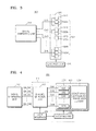
- FIG. 4 is a block diagram illustrating another example of a medical apparatus.
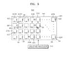
- FIG. 5 is a block diagram illustrating an example of a grouping unit of a medical apparatus.
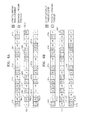
- FIG. 6A and 6B are block diagrams illustrating an example of adjacent ultrasound transducer elements grouped in an ultrasound transducer unit having an array of ultrasound transducer elements arranged in the form of a ring.
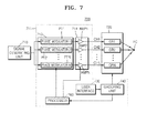
- FIG. 7 is a block diagram illustrating yet another example of a medical apparatus.
- FIG. 8 is a block diagram illustrating still another example of a medical apparatus in a diagnosis device used in diagnosing a lesion tissue of the human body.
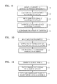
- FIG. 9 is a flowchart illustrating an example of a method of controlling a medical apparatus.
- FIG. 10 is a flowchart illustrating an example of a grouping of a plurality of ultrasound transducer elements in a method of controlling a medical apparatus.
- FIG. 11 is a flowchart illustrating an example of a generation of signals to be input according to groups in a method of controlling a medical apparatus.
- FIG. 1 is a diagram illustrating an example of a medical apparatus 100 in use.
- the medical apparatus 100 includes a signal generating unit 110, an ultrasound transducer unit 120, and a grouping unit 140. It will be understood by one of ordinary skill in the art that other general elements than the elements illustrated in FIG. 1 may be further included in the medical apparatus 100.
- the ultrasound transducer unit 120 is installed in a bed 102 on which a person 101 to be inspected is to lie.
- the signal generating unit 110 outputs a signal to the ultrasound transducer unit 120
- the ultrasound transducer unit 120 generates ultrasound from the outputted signal and irradiates the ultrasound onto a particular part of the person 101 requiring treatment or diagnosis.
- An example of the outputted signal is an electrical signal. However, this is only an example, and any other signal known to one of ordinary skill in the art may be used.
- FIG. 2 is a diagram illustrating an example the ultrasound transducer unit 120 of the medical apparatus 100.
- the example of the ultrasound transducer unit 120 illustrated in FIG. 2 is a concave type of focused ultrasonic transducer unit.
- focal points of ultrasound transducer elements 122 of the ultrasound transducer unit 120 are created corresponding to a region onto which ultrasound is to be irradiated.
- An example of the region onto which the ultrasound is to be irradiated is part of the breast, the liver, the abdomen, or any other organ or part of the human body known to one of ordinary skill in the art.
- the ultrasound transducer unit 120 in the example of FIG. 2 is only an example. Other units known to one of ordinary skill in the art to convert signals into ultrasound may be used.
- the ultrasound transducer unit 120 includes a plurality of ultrasound transducer elements 122 disposed on a disc-shaped support plate 121 having a concave middle part.
- Each of the ultrasound transducer elements 122 in this example modulates an electrical signal, which is outputted from the signal generating unit 110 and has a predetermined amplitude and phase, into ultrasound having a predetermined intensity and phase.
- the ultrasound transducer elements 122 in this example may be manufactured as piezoelectric transducers or any other elements known to one of ordinary skill in the art to modulate an electrical signal into ultrasound.
- Each ultrasound transducer element 122 of this example is focuses the generated ultrasound on a particular part of the body of the person 101 to be inspected requiring treatment or diagnosis.
- the ultrasound focused on the part to be irradiated is transformed into thermal energy, thereby causing a temperature of the irradiated part to rise and resulting in focal destruction or necrosis of a lesion tissue.
- ultrasound focused on the part to be irradiated and being partially reflected from tissue layers is transformed into electrical pulses using a probe, thereby resulting in the capture of an image of an inner tissue of the body.
- FIG. 3 is a block diagram illustrating an example of a medical apparatus 300.
- the medical apparatus 300 includes a signal generating unit 310, an ultrasound transducer unit 320, and a grouping unit 340. It will be understood by one of ordinary skill in the art that other general elements than the elements illustrated in FIG. 3 may be further included in the medical apparatus 300.
- a device configured to match impedances of the ultrasound transducer elements 322 of the ultrasound transducer unit 320 may be disposed between the signal generating unit 310 and the ultrasound transducer unit 320.
- the signal generating unit 310 outputs electrical signals to the ultrasound transducer unit 320 via output channels CH1 to CHN.
- one or more of the output channels CH1 to CHN of the signal generating unit 310 respectively outputs a common signal to two or more of the ultrasound transducer elements 322.
- the ultrasound transducer elements 322 in this example are grouped into a plurality of groups GR1 to GRN of the ultrasound transducer unit 320.
- Each of the output channels CH1 to CHN of the signal generating unit 310 respectively outputs an electrical signal according to the plurality of groups GR1 to GRN.
- FIG. 1 In the example of FIG. 1
- output channel CH1 outputs a common signal to a group GR1 of ultrasound transducer elements 322a
- output channel CH2 outputs a common signal to a group GR2 of ultrasound transducer elements 322b
- output channel CH3 outputs a common signal to a group GR3 containing an ultrasound transducer element 322c
- output channel CHN outputs a common signal to a group GRN of ultrasound transducer elements 322d.
- the grouping unit 140 groups ultrasound transducer elements 322 into two or more of the groups GR1 to GRN. Further, one or more of the groups GR1 to GRN includes two or more ultrasound transducer elements 322.
- FIG. 4 is a block diagram illustrating an example of a medical apparatus 400.
- the medical apparatus 400 includes a signal generating unit 410, an ultrasound transducer unit 420, and a control unit 411 including a channel selection unit 412, a user interface 430 and a grouping unit 440. Descriptions of the signal generating unit 410 and the ultrasound transducer unit 420 of FIG. 4 that would have been repeated from descriptions of the signal generating unit 310 and the ultrasound transducer unit 320 of FIG. 3 are omitted.
- the user interface 430 of the medical apparatus 400 allows a user to input instructions or information relating to ultrasound treatment therein.
- the user is a medical expert or any other entity known to one of ordinary skill in the art to need to input instructions or information relating to ultrasound treatment in a medical apparatus.
- the user may input grouping information, which includes the number of groups N of the ultrasound transducer elements to the user interface 430.
- the user interface 430 may be implemented with an input device, such as a keyboard, a mouse, or any other input device known to one of ordinary skill in the art, or a graphical user interface (GUI).
- GUI graphical user interface
- the signal generating unit 410 generates signals and outputs the signals outputs via a plurality of M channels SN_CH1 to SN_CHM.
- the channel selection unit 412 selects a plurality of output channels CH1 to CHN to output electrical signals according to groups of the ultrasound transducer unit 420 from among the plurality of M channels SN_CH1 to SN_CHM of the signal generating unit 410.
- the channel selection unit 412 outputs electrical signals via output channels CH1 to CHN according to groups made by the grouping unit 440.
- the number of output channels of the channel selection unit 412 are equal to the number of groups N of the ultrasound transducer unit 420.
- the number of groups N is less than the number of ultrasound transducer elements.
- the user inputs grouping information including the number of activated ultrasound transducer elements together with the number of groups N of the ultrasound transducer elements to the user interface 430.
- the grouping unit 440 groups the ultrasound transducer elements into activated ultrasound transducer elements EON and deactivated ultrasound transducer elements EOFF in consideration of the number of activated ultrasound transducer elements input by the user.
- the grouping unit 440 groups the activated ultrasound transducer elements EON into groups GR1 to GRN.
- the activated ultrasound transducer elements EON generate ultrasound in response to electrical signals according to groups GR1 to GRN.
- the deactivated ultrasound transducer elements EOFF are not connected to the output channels CH1 to CHN of the channel selection unit 412 and, as such, do not generate ultrasound.
- the channel selection unit 412 selects the output channels CH1 to CHN corresponding to the information regarding the input number of groups N from among the plurality of M channels SN_CH1 to SN_CHM.
- the channel selection unit 412 in this example may be implemented with a switching circuit to select N output channels from among M channels output by the signal generating unit 410.
- FIG. 5 is a block diagram illustrating an example of a grouping unit 540 of a medical apparatus.
- the grouping unit 540 of this example allows the ultrasound transducer elements 522 to be connected to each other according to grouping information of the ultrasound transducer elements 522 transmitted from a user interface.
- the grouping unit 540 includes a substrate 541, switches SR and SB implemented on the substrate 541, and a grouping processor 542.
- each of the ultrasound transducer elements 522 includes a switch SR switched to electrically short or isolate the ultrasound transducer elements 522 from right adjacent ultrasound transducer elements 522.
- each of the ultrasound transducer elements 522 in FIG. 5 includes a switch SB switched to electrically short or isolate the ultrasound transducer elements 522 from downward adjacent ultrasound transducer elements 522.
- the grouping processor 542 groups the ultrasound transducer elements 522 into activated ultrasound transducer elements EON and deactivated ultrasound transducer elements EOFF. In addition, the grouping processor 542 controls the switches SR and SB of the ultrasound transducer elements 522 to group the ultrasound transducer elements 522 into groups GR1 to GR4.
- FIG. 7 is a block diagram illustrating an example of a medical apparatus 700.
- the medical apparatus 700 includes a control unit 711 including a phase modulator 713, a signal amplifier 714, a user interface 730, a grouping unit 740, and a processor 760.
- different amplitudes and phases may be applied to electrical signals to be input to groups GR1 to GRN of a plurality of ultrasound transducer elements to focus ultrasound irradiated by the plurality of ultrasound transducer elements on a focus FC.
- Descriptions of the signal generating unit 710, the ultrasound transducer unit 720, the user interface 730, and the grouping unit 740 of FIG. 7 that would have been repeated from descriptions of elements in FIGS. 3 and 4 are omitted.
- the signal generating unit 710 generates electrical signals.
- the generated electrical signals are input to phase modulator elements PT1 to PTN of the phase modulator 713.
- the phase modulator elements PT1 to PTN modulate phases of the electrical signals input by the signal generating unit 710 and output the electrical signals having the modulated phases to amplifier elements AMP1 to AMPN of the signal amplifier 714.
- the phase modulator elements PT1 to PTN of the phase modulator 713 outputs electrical signals having different phases so that ultrasound signals generated from the ultrasound transducer elements that belong to different groups GR1 to GRN have different transmission delay times.
- the grouping unit 740 transmits grouping information to the processor 760 to control the phase modulator 713 by analyzing the transmitted grouping information and calculating phases of electrical signals to be modulated by the phase modulator elements PT1 to PTN.
- the amplifier elements AMP1 to AMPN of the signal amplifier 714 amplifies the electrical signals input from the phase modulator elements PT1 to PTN with appropriate gains to output the amplified electrical signals via output channels CH1 to CHN.
- the grouping unit 740 transmits the grouping information to the processor 160 to control the signal amplifier 714 by analyzing the transmitted grouping information and calculating gains of electrical signals to be amplified by the amplifier elements AMP1 to AMPN.
- control unit 711 controls the ultrasound transducer elements to generate ultrasound having different phases and intensities according to groups GR1 to GRN in response to electrical signals having different phases and amplitudes via the channels CH1 to CHN.
- the control unit 711 controls the ultrasound to have the same phase and intensity when ultrasound irradiated according to groups GR1 to GRN reaches the focus FC on which the ultrasound is to be focused.
- the control unit 711 controls the phases and amplitudes of the electrical signals input to the groups GR1 to GRN of the ultrasound transducer unit 720 to vary the position of the focus FC on which the ultrasound is to be focused within a predetermined target region that requires treatment or diagnosis, i.e., a region onto which the ultrasound is to be irradiated.
- the control unit 711 controls the ultrasound transducer unit 720 to make a multi-focus using the ultrasound generated from the ultrasound transducer unit 720.
- the processor 760 groups the groups GR1 to GRN of the ultrasound transducer unit 720 into first groups and second groups.
- the processor 760 controls the phase modulator elements PT1 to PTN of the phase modulator 713 and the amplifier elements AMP1 to AMPN of the signal amplifier 714 relating to the electrical signals applied to the first groups via output channels to irradiate the ultrasound therefrom onto a first focal position by using the ultrasound transducer elements of the first groups.
- the processor 760 controls the phase modulator elements PT1 to PTN of the phase modulator 713 and the amplifier elements AMP1 to AMPN of the signal amplifier 714 relating to the electrical signals applied to the second groups via output channels to irradiate the ultrasound therefrom onto a second focal position by using the ultrasound transducer elements of the second groups.
- FIG. 8 is a block diagram illustrating an example of a medical apparatus 800 in a diagnosis device 200 used in diagnosing a lesion tissue of the human body
- a diagnosis device 200 includes the medical apparatus 800, a receiving probe 851, an image processor 852, an image generating unit 853, and a display unit 854.
- the medical apparatus 800 includes a signal generating unit 810, an ultrasound transducer unit 820, a user interface 830, and a grouping unit 840. Descriptions of the medical apparatus 800, the signal generating unit 810, the ultrasound transducer unit 820, the user interface 830, and the grouping unit 840 of FIG. 8 that would have been repeated from descriptions of elements in FIGS. 1 , 3 , 4 , and 7 are omitted.
- the receiving probe 851 of this example may be manufactured as a piezoelectric transducer or any other elements known to one of ordinary skill in the art to modulate ultrasound into an electrical signal.
- ultrasound is transferred by the medical apparatus 800 to a particular part of the body, the ultrasound is partially reflected from or diffracted at layers between different tissues.
- the ultrasound is reflected from a place of the body where densities of blood cells in blood plasma, structures in organs, or any other organs or tissues known to one of ordinary skill in the art vary or are diffracted at a space between the structures.
- the ultrasound transducer unit 820 When an HIFU transducer unit is used, the ultrasound transducer unit 820 generates ultrasonic signals US1 to USN according to groups GR1 to GRN, and the ultrasonic signals US1 to USN irradiated by the ultrasound transducer unit 120 are concentratively reflected from or diffracted at the focus FC. In this way, ultrasound irradiated by a plurality of ultrasound transducer elements is transmitted to the focus FC and are collectively reflected from or diffracted at the focus FC.
- the receiving probe 851 outputs electrical pulses having predetermined amplitudes and phases according to the vibrations.
- the image processor 852 performs image processing on the electrical pulses output from the receiving probe 851 to generate image data.
- the image generating unit 853 generates ultrasound images based on the image data. For example, the image generating unit 853 transforms the image data according to a format of the display unit 854 to generate ultrasound images. In addition, the image generating unit 853 transmits the generated ultrasound images to the display unit 854.
- the ultrasound images generated by the image generating unit 853 are displayed in graphics on the display unit 854.
- An example of the display unit 854 may be a liquid crystal display (LCD) screen or any device known to one of ordinary skill in the art to display ultrasound images on a screen, paper, or space.
- LCD liquid crystal display
- the receiving probe 851 may include one or more transducer elements.
- the one or more transducer elements of the receiving probe 851 may be a piezoelectric transducer separated from the ultrasound transducer unit 820 or any other elements known to one of ordinary skill in the art to modulate ultrasound into an electrical signal that is separated from the ultrasound transducer unit 820.
- the receiving probe 851 may include one or more ultrasound transducer elements of the ultrasound transducer unit 820.
- the ultrasound transducer elements that constitute the receiving probe 851 are not limited to performing of a function of receiving ultrasound signals reflected from the body and may simultaneously perform a function of irradiating the ultrasound signals onto the body or any other function known to one of ordinary skill in the art that is able to be performed by ultrasound transducer elements.
- the ultrasound images generated by the ultrasound imaging device may be a variety of images in a B-mode, a Doppler mode, or any other mode known to one of ordinary skill in the art in which an ultrasound image may be generated.
- the ultrasound images may have a two-dimensional or three-dimensional shape. Three-dimensional ultrasound images are appropriate to provide stereoscopic ultrasound images by using x-, y-, and z-axes.
- the three-dimensional ultrasound images may be generated by using three-dimensional receiving signals input to a plurality of transducers or a combination of a plurality of two-dimensional image data.
- FIG. 9 is a flowchart illustrating an example of a method of controlling a medical apparatus.
- the method of controlling a medical apparatus illustrated in FIG. 9 may be implemented by the medical apparatuses 100, 300, 400, 700, and 800 of FIGS. 1 , 3 , 4 , 7 , and 8 , respectively.
- descriptions of the medical apparatuses 100, 300, 400, 700, and 800 of FIGS. 1 , 3 , 4 , 7 , and 8 may also be applied to the example of the method of controlling a medical apparatus illustrated in FIG. 9 .
- a plurality of ultrasound transducer elements of an ultrasound transducer unit are grouped (10) into a plurality of groups.
- FIG. 10 is a flowchart illustrating an example of a grouping of a plurality of ultrasound transducer elements in a method of controlling a medical apparatus.
- a user inputs (11) grouping information to a user interface.
- the user is a medical expert or any other entity known to one of ordinary skill in the art to need to input instructions or information relating to ultrasound treatment in a medical apparatus.
- the grouping information may include the number of groups of a plurality of ultrasound transducer elements, the number of activated ultrasound transducer elements, or any other information known to one of ordinary skill in the art to assist in grouping ultrasound transducer elements.
- a number of groups N is equal to or greater than 2 and equal to or less than (n-1), and a number k of activated ultrasound transducer elements is equal to or greater than (N+1) and equal to or less than n. This is because two or more ultrasound transducer elements may be included in one or more of the number of groups N.
- Activated ultrasound transducer elements and deactivated ultrasound transducer elements are sampled (12) from among the ultrasound transducer elements.
- the activated ultrasound transducer elements are grouped (13) into the inputted number of groups N of the grouping information. If the grouping information regarding all ultrasound transducer elements is input, the number of groups N is grouped according to the input grouping information. If only information regarding the number of groups N and the number k of activated ultrasound transducer elements is input, the k activated ultrasound transducer elements are grouped randomly into the number of groups N groups.
- FIG. 6A and 6B are block diagrams illustrating an example of adjacent ultrasound transducer elements 122 grouped in an ultrasound transducer unit 120 having an array of ultrasound transducer elements 122 arranged in the form of a ring. That is, the example of the ultrasound transducer unit 120 illustrated in FIG. 2 has a structure in which a plurality of rings having different sizes, in which the ultrasound transducer elements 122 are arranged to form a circle in a lateral direction, are combined with each other in a vertical direction.
- FIGS. 6A and 6B each illustrate an array of ultrasound transducer elements 122 arranged in the form of three rings in the vertical directions.
- the ultrasound transducer elements 122 of FIG. 6A and 6B have a sparse-array structure.
- the sparse-array structure refers to an arrangement in which some unsampled ultrasound transducer elements are deactivated and sampled ultrasound transducer elements are selected to perform signal processing.
- the grouping of the ultrasound transducer elements 122 are performed as a group of adjacent activated ultrasound transducer elements 122 in a single ring, as illustrated in the example of FIG. 6A , or as a group of adjacent ultrasound transducer elements 122 in adjacent rings, as illustrated in the example of FIG. 6B .
- a distance between the adjacent activated ultrasound transducer elements is insignificantly less than a distance at which the adjacent activated ultrasound transducer elements reach a focus. Therefore, ultrasonic signals having the same phase may be transmitted onto the focus of a target region onto which ultrasound is to be irradiated, even though phases or amplitudes of ultrasound signals are the same. As a result, adjacent activated ultrasound transducer elements may be grouped into the same group.
- Patterns of distribution of activated ultrasound transducer elements and deactivated ultrasound transducer elements may be irregularly and randomly selected. This is because, when activated ultrasound transducer elements have a regular array arrangement, ultrasonic signals may be focused on other regions than the focus within the target region onto which ultrasound is to be irradiated.
- a grouping unit of this example uses a genetic algorithm as an optimization technique to sample activated ultrasound transducer elements or group the activated ultrasound transducer elements.
- the genetic algorithm refers to a method of obtaining an optimum solution by using genetic manipulation and performance, which are obtained in an evolution procedure.
- the grouping unit of this example generates a set of individuals.
- the individuals are samplings and groupings of activated ultrasound transducer elements.
- the grouping unit evaluates performance of the individuals to select one of the individuals to be meticulously evaluated.
- the grouping unit generates a next generation set by performing manipulations, such as cross-linking, mutation, or any other manipulation known to one of ordinary skill in the art, on each of the individuals. As these manipulations are repeatedly performed, if the number of individuals having high performance increases by overlaying generations, the probability that an individual closest to an optimum solution may be generated increases.
- performance evaluation of the individuals may include an object function of a grating lobe region.
- the grating lobe refers to a measurement of ultrasonic signals focused in other regions than the focus within the target region onto which ultrasound is to be irradiated.
- an individual that may minimize the grating lobe may be obtained as an optimum solution.
- signals to be input according to groups are generated (20).
- FIG. 11 is a flowchart illustrating an example of a generation of signals to be input according to groups in a method of controlling a medical apparatus.
- a signal generating unit generates (21) source signals.
- the source signals are generated and inputted to a channel selection unit 412 via a plurality of input channels.
- the source signals are generated and inputted to the channel selection unit 412 via a plurality of M channels SN_CH1 to SN_CHM.
- the channel selection unit selects (22) output channels having a number of groups from among the input channels to output electrical signals according to groups of the plurality of ultrasound transducer elements. For example, in FIG. 4 , the channel selection unit 412 selects output channels CH1 to CHN having the number of groups N from among the input channels SN_CH1 to SN_CHM to output electrical signals according to groups of the plurality of ultrasound transducer elements.
- the channel selection unit 412 selects N channels CH1 to CHN according to the input information regarding the number of groups N. If the user does not input the number of groups N of the ultrasound transducer unit 420 to the user interface 430, the channel selection unit 412 is designed to select a predetermined number of channels according to predetermined settings.
- Phases and amplitudes of the source signals input via the input channels are modulated (23).
- the electrical signals generated by the signal generating unit 710 are input to the phase modulator 713, and phases of the electrical signals are modulated by phase modulator elements PT1 to PTN.
- amplifier elements AMP1 to AMPN of the signal amplifier 714 amplify the signals input from the phase modulator elements PT1 to PTN with appropriate gains, thereby outputting electrical signals via the output channels CH1 to CHN.
- the grouping unit 740 transmits grouping information to the processor 760, and the processor 760 controls the phase modulator 713 and the signal amplifier 714, respectively, by analyzing the transmitted grouping information and calculating phases of electrical signals to be modulated by the phase modulator elements PT1 to PTN and calculating gains of the electrical signals to be amplified by the amplifier elements AMP1 to AMPN.
- different amplitudes and phases are applied to electrical signals input to the groups GP1 to GPN of the ultrasound transducer elements.
- the ultrasound signals generated from the ultrasound transducer elements that belong to different groups have different transmission delay times to compensate for the distance between the ultrasound transducer elements and the focus FC.
- the ultrasound irradiated by the plurality of ultrasound transducer elements is focused on the focus FC.
- the phases and amplitudes of the electrical signals input to the groups of the ultrasound transducer unit 720 are controlled so that a position of the focus FC on which ultrasound is focused may vary with a predetermined target region that requires treatment or diagnosis, i.e., in a region onto which the ultrasound is to be irradiated.
- the phases and amplitudes of the electrical signals input to the groups of the ultrasound transducer unit 720 are controlled so that the ultrasound generated from the ultrasound transducer unit 720 may make a multi-focus.
- the signal generating unit inputs (30) the electrical signals to the plurality of output channels according to groups of the ultrasound transducer unit.
- one or more of the output channels of the signal generating unit outputs a common signal to two or more ultrasound transducer elements.
- the ultrasound transducer unit generates (40) ultrasound signals from the electrical signals input according to groups.
- Ultrasound is irradiated (50) onto a particular part of the body of the person to be inspected that requires treatment or diagnosis of lesion. Accordingly, ultrasound images of lesions or a diagnosis of a disease to be removed is generated.
- ultrasound requires an intensity that is much less than intensity required in ultrasound used to remove lesions.
- Ultrasounds that are focused on the irradiated part and are partially reflected from or diffracted at tissue layers may be transformed into electrical pulses by using a probe and used in capturing images of tissues of the body. That is, with reference to the example illustrated in FIG. 8 , the ultrasound signals that are reflected from or diffracted at the body may vibrate the piezoelectric transducer of the receiving probe 851, and the piezoelectric transducer may output electrical pulses having predetermined amplitudes and phases according to the vibrations.
- the electrical pulses output from the receiving probe 851 are input to the image processor 852 and are processed so that image data is generated.
- the image generating unit 853 generates ultrasound images based on the image data. In addition, the image generating unit 853 transmits the generated ultrasound images to the display unit 854, and the ultrasound images are displayed in graphics on the display unit 854.
- a processing device may be implemented using one or more general-purpose or special purpose computers, such as, for example, a processor, a controller and an arithmetic logic unit, a digital signal processor, a microcomputer, a field programmable array, a programmable logic unit, a microprocessor or any other device capable of responding to and executing instructions in a defined manner.
- the processing device may run an operating system (OS) and one or more software applications that run on the OS.
- OS operating system
- the processing device also may access, store, manipulate, process, and create data in response to execution of the software.
- a processing device may include multiple processing elements and multiple types of processing elements.
- a processing device may include multiple processors or a processor and a controller.
- different processing configurations are possible, such a parallel processors.
- a processing device configured to implement a function A includes a processor programmed to run specific software.
- a processing device configured to implement a function A, a function B, and a function C may include configurations, such as, for example, a processor configured to implement both functions A, B, and C, a first processor configured to implement function A, and a second processor configured to implement functions B and C, a first processor to implement function A, a second processor configured to implement function B, and a third processor configured to implement function C, a first processor configured to implement function A, and a second processor configured to implement functions B and C, a first processor configured to implement functions A, B, C, and a second processor configured to implement functions A, B, and C, and so on.
- the software may include a computer program, a piece of code, an instruction, or some combination thereof, for independently or collectively instructing or configuring the processing device to operate as desired.
- Software and data may be embodied permanently or temporarily in any type of machine, component, physical or virtual equipment, computer storage medium or device, or in a propagated signal wave capable of providing instructions or data to or being interpreted by the processing device.
- the software also may be distributed over network coupled computer systems so that the software is stored and executed in a distributed fashion.
- the software and data may be stored by one or more computer readable recording mediums.
- the computer readable recording medium may include any data storage device that can store data which can be thereafter read by a computer system or processing device. Examples of the computer readable recording medium include read-only memory (ROM), random-access memory (RAM), CD-ROMs, magnetic tapes, floppy disks, optical data storage devices.
- Program instructions to perform a method described herein, or one or more operations thereof, may be recorded, stored, or fixed in one or more computer-readable storage media.
- the program instructions may be implemented by a computer.
- the computer may cause a processor to execute the program instructions.
- the media may include, alone or in combination with the program instructions, data files, data structures, and the like.
- Examples of computer-readable storage media include magnetic media, such as hard disks, floppy disks, and magnetic tape; optical media such as CD ROM disks and DVDs; magneto-optical media, such as optical disks; and hardware devices that are specially configured to store and perform program instructions, such as read-only memory (ROM), random access memory (RAM), flash memory, and the like.
- Examples of program instructions include machine code, such as produced by a compiler, and files containing higher level code that may be executed by the computer using an interpreter.
- the program instructions that is, software, may be distributed over network coupled computer systems so that the software is stored and executed in a distributed fashion.
- the software and data may be stored by one or more computer readable storage mediums.
- the described unit to perform an operation or a method may be hardware, software, or some combination of hardware and software.
- the unit may be a software package running on a computer or the computer on which that software is running.
- the disclosure discloses the following further aspects.
- the aspect of a medical apparatus comprising: an ultrasound transducer unit comprising a plurality of ultrasound transducer elements, the ultrasound transducer elements being configured to transform signals into ultrasound and output the transformed ultrasound; a grouping unit configured to group the ultrasound transducer elements into a plurality of groups; and a signal generating unit configured to generate the signals to be transformed into the ultrasound and output the generated signals to the groups via a plurality of output channels respectively corresponding to the groups.
- the signal generating unit is further configured to output one or more common signals of the signals to be transformed into the ultrasound via one or more of the output channels, respectively, to respective ones of the groups comprising two or more of the ultrasound transducer elements.
- the medical apparatus further comprising: a channel selection unit configured to select two or more of the output channels via which the signals to be transformed into the ultrasound are to be output to the groups.
- the medical apparatus according to the third aspect, further comprising: a user interface configured to receive grouping information specifying a quantity of the groups in which the ultrasound transducer elements are to be grouped, wherein the channel selection unit is further configured to select the two or more of the output channels according to the received grouping information.
- the grouping unit is further configured to group the ultrasound transducer elements into activated ultrasound transducer elements and deactivated ultrasound transducer elements, and group the activated ultrasound transducer elements into two or more groups.
- the medical apparatus further comprising: a user interface configured to receive grouping information specifying a quantity of the activated ultrasound transducer elements to be input, wherein the grouping unit is further configured to group the activated ultrasound transducer elements and deactivated ultrasound transducer elements according to the received grouping information.
- the medical apparatus according to the fifth aspect wherein the grouping unit is further configured to sample the activated ultrasound transducer elements and the deactivated ultrasound transducer elements via random extraction.
- the medical apparatus further comprising: a phase modulator configured to modulate phase of the signals to be outputted to the groups to form a focus of the ultrasound transducer unit in a target region onto which the ultrasound is to be irradiated; and a signal amplifier configured to amplify amplitudes of the phase modulated signals.
- the medical apparatus according to the ninth aspect, further comprising: a processor configured to calculate phases and amplification gains of the signals to be outputted to the groups to control the phase modulator and the signal amplifier, the phases and the amplification gains being calculated according to grouping information transmitted from the grouping unit.
- the medical apparatus wherein the processor is further configured to control the phase modulator and the signal amplifier to form a multi-focus from the ultrasound irradiated by the ultrasound transducer unit in response to the signals outputted to the groups.
- the aspect of a method of controlling a medical apparatus comprising: grouping a plurality of ultrasound transducer elements of an ultrasound transducer unit into a plurality of groups; generating signals to be transformed into ultrasound; and outputting the signals to be transformed into the ultrasound to the groups via a plurality of output channels respectively corresponding to the groups.
- the method according to the twelfth aspect further comprising: outputting one or more common signals of the signals to be transformed into the ultrasound via one or more of the output channels, respectively, to respective ones of the groups comprising two or more of the ultrasound transducer elements.
- the method according to the twelfth aspect wherein the generating and the outputting of the signals to be transformed into the ultrasound comprises selecting two or more of the output channels via which the signals to be transformed into the ultrasound are to be output to the groups.
- the selecting of the output channels comprises receiving grouping information and selecting the two or more of the output channels, the received grouping information specifying a quantity of the groups in which the ultrasound transducer elements are to be grouped, the two or more of the output channels being selected according to the received grouping information.
- the grouping of the plurality of ultrasound transducer elements comprises grouping the ultrasound transducer elements into activated ultrasound transducer elements and deactivated ultrasound transducer elements and grouping the activated ultrasound transducer elements into two or more groups.
- the method according to the sixteenth aspect further comprising: sampling the activated ultrasound transducer elements and the deactivated ultrasound transducer elements via random extraction.
- the method according to the twelfth aspect wherein the grouping of the plurality of ultrasound transducer elements comprises grouping adjacent ones of the ultrasound transducer elements into a single group.
- controlling of the signals comprises calculating phases and amplification gains of the signals to be outputted to the groups and modulating the phases and amplifying amplitudes of the signals to be outputted to the groups to form the focus of the ultrasound transducer unit in the target region onto which the ultrasound is to be irradiated, the phases and the amplification gains being calculated according to grouping information specifying a quantity of the groups in which the ultrasound transducer elements are to be grouped.
- the method according to the nineteenth aspect further comprising: controlling the signals to be outputted to the groups of the ultrasound transducer unit to form a multi-focus from the ultrasound irradiated by the ultrasound transducer unit in response to the signals outputted to the groups.
Landscapes
- Health & Medical Sciences (AREA)
- Life Sciences & Earth Sciences (AREA)
- Engineering & Computer Science (AREA)
- Biomedical Technology (AREA)
- Nuclear Medicine, Radiotherapy & Molecular Imaging (AREA)
- Animal Behavior & Ethology (AREA)
- General Health & Medical Sciences (AREA)
- Public Health (AREA)
- Veterinary Medicine (AREA)
- Radiology & Medical Imaging (AREA)
- Physics & Mathematics (AREA)
- Surgery (AREA)
- Heart & Thoracic Surgery (AREA)
- Medical Informatics (AREA)
- Molecular Biology (AREA)
- Acoustics & Sound (AREA)
- Multimedia (AREA)
- Gynecology & Obstetrics (AREA)
- Biophysics (AREA)
- Pathology (AREA)
- Otolaryngology (AREA)
- Surgical Instruments (AREA)
- Ultra Sonic Daignosis Equipment (AREA)
Applications Claiming Priority (1)
| Application Number | Priority Date | Filing Date | Title |
|---|---|---|---|
| KR1020110089865A KR20130026327A (ko) | 2011-09-05 | 2011-09-05 | 초음파 의료 장치 및 이의 제어 방법 |
Publications (2)
| Publication Number | Publication Date |
|---|---|
| EP2564899A1 true EP2564899A1 (fr) | 2013-03-06 |
| EP2564899B1 EP2564899B1 (fr) | 2014-12-24 |
Family
ID=46682710
Family Applications (1)
| Application Number | Title | Priority Date | Filing Date |
|---|---|---|---|
| EP12180093.2A Not-in-force EP2564899B1 (fr) | 2011-09-05 | 2012-08-10 | Appareil médical |
Country Status (5)
| Country | Link |
|---|---|
| US (1) | US20130060170A1 (fr) |
| EP (1) | EP2564899B1 (fr) |
| JP (1) | JP2013052244A (fr) |
| KR (1) | KR20130026327A (fr) |
| CN (1) | CN102974046A (fr) |
Families Citing this family (36)
| Publication number | Priority date | Publication date | Assignee | Title |
|---|---|---|---|---|
| US8444562B2 (en) | 2004-10-06 | 2013-05-21 | Guided Therapy Systems, Llc | System and method for treating muscle, tendon, ligament and cartilage tissue |
| US8535228B2 (en) | 2004-10-06 | 2013-09-17 | Guided Therapy Systems, Llc | Method and system for noninvasive face lifts and deep tissue tightening |
| US10864385B2 (en) | 2004-09-24 | 2020-12-15 | Guided Therapy Systems, Llc | Rejuvenating skin by heating tissue for cosmetic treatment of the face and body |
| US9694212B2 (en) | 2004-10-06 | 2017-07-04 | Guided Therapy Systems, Llc | Method and system for ultrasound treatment of skin |
| US9827449B2 (en) | 2004-10-06 | 2017-11-28 | Guided Therapy Systems, L.L.C. | Systems for treating skin laxity |
| US8133180B2 (en) | 2004-10-06 | 2012-03-13 | Guided Therapy Systems, L.L.C. | Method and system for treating cellulite |
| US11235179B2 (en) | 2004-10-06 | 2022-02-01 | Guided Therapy Systems, Llc | Energy based skin gland treatment |
| US8690778B2 (en) | 2004-10-06 | 2014-04-08 | Guided Therapy Systems, Llc | Energy-based tissue tightening |
| US11883688B2 (en) | 2004-10-06 | 2024-01-30 | Guided Therapy Systems, Llc | Energy based fat reduction |
| EP2279699B1 (fr) | 2004-10-06 | 2019-07-24 | Guided Therapy Systems, L.L.C. | Procédé pour l'amélioration cosmétique non invasive de la cellulite |
| KR20240113495A (ko) | 2004-10-06 | 2024-07-22 | 가이디드 테라피 시스템스, 엘.엘.씨. | 초음파 치료 시스템 |
| US20060111744A1 (en) | 2004-10-13 | 2006-05-25 | Guided Therapy Systems, L.L.C. | Method and system for treatment of sweat glands |
| US11207548B2 (en) | 2004-10-07 | 2021-12-28 | Guided Therapy Systems, L.L.C. | Ultrasound probe for treating skin laxity |
| US11724133B2 (en) | 2004-10-07 | 2023-08-15 | Guided Therapy Systems, Llc | Ultrasound probe for treatment of skin |
| KR102087909B1 (ko) | 2008-06-06 | 2020-03-12 | 얼테라, 인크 | 코스메틱 치료 시스템 |
| US12102473B2 (en) | 2008-06-06 | 2024-10-01 | Ulthera, Inc. | Systems for ultrasound treatment |
| JP2012513837A (ja) | 2008-12-24 | 2012-06-21 | ガイデッド セラピー システムズ, エルエルシー | 脂肪減少および/またはセルライト処置のための方法およびシステム |
| US9510802B2 (en) | 2012-09-21 | 2016-12-06 | Guided Therapy Systems, Llc | Reflective ultrasound technology for dermatological treatments |
| JP5973060B2 (ja) * | 2012-10-07 | 2016-08-23 | メイヨ フォンデーシヨン フォー メディカル エジュケーション アンド リサーチ | 超音波トランスデューサ素子の下位集合を用いて超音波を送信することによるせん断波エラストグラフィのシステムおよび方法 |
| CN204017181U (zh) | 2013-03-08 | 2014-12-17 | 奥赛拉公司 | 美学成像与处理系统、多焦点处理系统和执行美容过程的系统 |
| KR20160007516A (ko) * | 2013-06-28 | 2016-01-20 | 알피니언메디칼시스템 주식회사 | 다수의 어레이가 병렬구조로 연결된 초음파 프로브 및 이를 구비한 초음파 영상 진단장치 |
| JP6311236B2 (ja) | 2013-08-20 | 2018-04-18 | 東京エレクトロン株式会社 | 基板洗浄装置 |
| SG11201608691YA (en) | 2014-04-18 | 2016-11-29 | Ulthera Inc | Band transducer ultrasound therapy |
| KR102560033B1 (ko) * | 2015-11-09 | 2023-07-26 | 삼성전자주식회사 | 프로브 장치 및 그 제어 방법 |
| CA3007665A1 (fr) | 2016-01-18 | 2017-07-27 | Ulthera, Inc. | Dispositif a ultrasons compact possedant un reseau a ultrasons peripherique annulaire electriquement connecte a une carte de circuit imprime flexible et son procede d'assemblage |
| US11406848B2 (en) | 2016-06-28 | 2022-08-09 | Sogang University Research Foundation | Ultrasonic therapy device using HIFU and control method thereof |
| IL264440B (en) | 2016-08-16 | 2022-07-01 | Ulthera Inc | Systems and methods for cosmetic treatment of the skin using ultrasound |
| TW202529848A (zh) | 2018-01-26 | 2025-08-01 | 美商奧賽拉公司 | 用於多個維度中的同時多聚焦超音治療的系統和方法 |
| WO2019164836A1 (fr) | 2018-02-20 | 2019-08-29 | Ulthera, Inc. | Systèmes et procédés de traitement cosmétique combiné de la cellulite par ultrasons |
| KR102117485B1 (ko) * | 2018-09-14 | 2020-06-02 | 재단법인 대구경북첨단의료산업진흥재단 | 다중채널 초음파 자극기 |
| JP2022513577A (ja) | 2018-11-30 | 2022-02-09 | ウルセラ インコーポレイテッド | 超音波処置の効能を増強させるためのシステムおよび方法 |
| CA3137928A1 (fr) | 2019-07-15 | 2021-01-21 | Ulthera, Inc. | Systemes et procedes de mesure de l'elasticite par imagerie d'ondes de cisaillement multi-foyer a ultrasons dans de multiples dimensions |
| CN110784268B (zh) * | 2019-10-29 | 2021-03-30 | 华南理工大学 | 基于分组索引调制的超声波人体内通信方法及装置 |
| CN115919371A (zh) * | 2022-12-29 | 2023-04-07 | 西安华峰医疗科技有限公司 | 一种多超声通路成像系统 |
| KR102921303B1 (ko) * | 2023-01-30 | 2026-01-30 | 서강대학교산학협력단 | 치료 초음파 장치 및 이를 포함하는 치료 초음파 시스템 |
| KR20240171285A (ko) * | 2023-05-30 | 2024-12-09 | 알피니언메디칼시스템 주식회사 | 초음파 출력 장치 및 이를 이용한 초점 제어 방법 |
Citations (3)
| Publication number | Priority date | Publication date | Assignee | Title |
|---|---|---|---|---|
| EP1936404A1 (fr) * | 2006-12-18 | 2008-06-25 | Aloka Co., Ltd. | Appareil de diagnostic à ultrasons |
| US20100030076A1 (en) * | 2006-08-01 | 2010-02-04 | Kobi Vortman | Systems and Methods for Simultaneously Treating Multiple Target Sites |
| WO2011024074A2 (fr) * | 2009-08-26 | 2011-03-03 | Insightec Ltd. | Transducteur à ultrasons asymétrique en réseau phasé |
Family Cites Families (7)
| Publication number | Priority date | Publication date | Assignee | Title |
|---|---|---|---|---|
| US6692450B1 (en) * | 2000-01-19 | 2004-02-17 | Medtronic Xomed, Inc. | Focused ultrasound ablation devices having selectively actuatable ultrasound emitting elements and methods of using the same |
| WO2005050252A1 (fr) * | 2003-11-20 | 2005-06-02 | Koninklijke Philips Electronics, N.V. | Imagerie de diagnostic ultrasonique a ajustement automatique des parametres de mise en forme du faisceau |
| US8608672B2 (en) * | 2005-11-23 | 2013-12-17 | Insightec Ltd. | Hierarchical switching in ultra-high density ultrasound array |
| US20080097252A1 (en) * | 2006-08-25 | 2008-04-24 | Eilaz Babaev | Ultrasound and Pressure Therapy Wound Care Device |
| US8532940B2 (en) * | 2009-02-18 | 2013-09-10 | Fbs, Inc. | Systems and methods for the inspection of structures having unknown properties |
| RU2563061C2 (ru) * | 2009-12-28 | 2015-09-20 | Конинклейке Филипс Электроникс Н.В. | Оптимизация преобразователя сфокусированного ультразвука высокой интенсивности |
| US8622909B1 (en) * | 2010-10-19 | 2014-01-07 | Quantason, LLC | Method of locating the position of a microcalcification in a human breast |
-
2011
- 2011-09-05 KR KR1020110089865A patent/KR20130026327A/ko not_active Withdrawn
-
2012
- 2012-08-03 US US13/565,979 patent/US20130060170A1/en not_active Abandoned
- 2012-08-10 EP EP12180093.2A patent/EP2564899B1/fr not_active Not-in-force
- 2012-09-05 JP JP2012195007A patent/JP2013052244A/ja active Pending
- 2012-09-05 CN CN2012103253629A patent/CN102974046A/zh active Pending
Patent Citations (3)
| Publication number | Priority date | Publication date | Assignee | Title |
|---|---|---|---|---|
| US20100030076A1 (en) * | 2006-08-01 | 2010-02-04 | Kobi Vortman | Systems and Methods for Simultaneously Treating Multiple Target Sites |
| EP1936404A1 (fr) * | 2006-12-18 | 2008-06-25 | Aloka Co., Ltd. | Appareil de diagnostic à ultrasons |
| WO2011024074A2 (fr) * | 2009-08-26 | 2011-03-03 | Insightec Ltd. | Transducteur à ultrasons asymétrique en réseau phasé |
Also Published As
| Publication number | Publication date |
|---|---|
| KR20130026327A (ko) | 2013-03-13 |
| JP2013052244A (ja) | 2013-03-21 |
| US20130060170A1 (en) | 2013-03-07 |
| EP2564899B1 (fr) | 2014-12-24 |
| CN102974046A (zh) | 2013-03-20 |
Similar Documents
| Publication | Publication Date | Title |
|---|---|---|
| EP2564899B1 (fr) | Appareil médical | |
| US10219785B2 (en) | Method, apparatus, and high intensity focused ultrasound (HIFU) system for generating ultrasound that forms multi-foci via medical image in region of interest | |
| CN110248606B (zh) | 气穴定位 | |
| JP5480280B2 (ja) | 物体の物理的特性の検査 | |
| CN105339045B (zh) | 超声治疗的频率优化 | |
| US11684807B2 (en) | Optimization of transducer configurations in ultrasound procedures | |
| US8155725B2 (en) | Method for optimising the focussing of waves through an aberration-inducing element | |
| US7587291B1 (en) | Focusing of broadband acoustic signals using time-reversed acoustics | |
| CN113710163A (zh) | 用于调节超声手术中的微泡的系统和方法 | |
| US20110066032A1 (en) | Asymmetric ultrasound phased-array transducer | |
| CN109091768A (zh) | 使用交叉点开关矩阵的超声聚焦 | |
| CN112349446B (zh) | 一种操控方法及声镊装置 | |
| US20140081145A1 (en) | Multi-channel hemispherical ultrasonic wave transmit and receiving detection system and method | |
| US20140236051A1 (en) | Apparatus and method of transmitting ultrasound | |
| US20140207051A1 (en) | Method and apparatus for controlling ultrasound system | |
| WO2024139721A1 (fr) | Dispositif de diagnostic et de traitement par ultrasons | |
| RU2608433C2 (ru) | Устройство, выполняющее тестовые обработки ультразвуком с использованием высокоинтенсивного фокусированного ультразвука | |
| US20140236050A1 (en) | Method, apparatus, and hifu system for generating ultrasound that form multi-foci in region of interest | |
| Grondin et al. | Real-time monitoring of high intensity focused ultrasound (HIFU) ablation of in vitro canine livers using harmonic motion imaging for focused ultrasound (HMIFU) | |
| KR20130016038A (ko) | 소형 치료 초음파 트랜스듀서를 이용한 고강도 집속 초음파 치료 시스템 | |
| CN104582587A (zh) | 具有倾斜度信息的超声波探测器和使用该探测器进行超声波诊断和治疗的设备 | |
| KR20130088478A (ko) | 초음파 트랜스듀서 어레이의 다중 초점 형성 방법 및 장치. | |
| KR102415740B1 (ko) | 탈부착이 가능한 음향 렌즈를 이용한 초음파 진단-치료 장치 | |
| CN113826025A (zh) | 用于生成剪切波的方法和装置 | |
| US9380945B2 (en) | Method and apparatus for generating a temperature image |
Legal Events
| Date | Code | Title | Description |
|---|---|---|---|
| PUAI | Public reference made under article 153(3) epc to a published international application that has entered the european phase |
Free format text: ORIGINAL CODE: 0009012 |
|
| AK | Designated contracting states |
Kind code of ref document: A1 Designated state(s): AL AT BE BG CH CY CZ DE DK EE ES FI FR GB GR HR HU IE IS IT LI LT LU LV MC MK MT NL NO PL PT RO RS SE SI SK SM TR |
|
| AX | Request for extension of the european patent |
Extension state: BA ME |
|
| 17P | Request for examination filed |
Effective date: 20130902 |
|
| RBV | Designated contracting states (corrected) |
Designated state(s): AL AT BE BG CH CY CZ DE DK EE ES FI FR GB GR HR HU IE IS IT LI LT LU LV MC MK MT NL NO PL PT RO RS SE SI SK SM TR |
|
| 17Q | First examination report despatched |
Effective date: 20131001 |
|
| RIC1 | Information provided on ipc code assigned before grant |
Ipc: A61B 8/08 20060101ALN20140507BHEP Ipc: A61N 7/02 20060101AFI20140507BHEP Ipc: A61N 7/00 20060101ALI20140507BHEP Ipc: G10K 11/34 20060101ALI20140507BHEP |
|
| GRAP | Despatch of communication of intention to grant a patent |
Free format text: ORIGINAL CODE: EPIDOSNIGR1 |
|
| INTG | Intention to grant announced |
Effective date: 20140630 |
|
| GRAS | Grant fee paid |
Free format text: ORIGINAL CODE: EPIDOSNIGR3 |
|
| GRAA | (expected) grant |
Free format text: ORIGINAL CODE: 0009210 |
|
| AK | Designated contracting states |
Kind code of ref document: B1 Designated state(s): AL AT BE BG CH CY CZ DE DK EE ES FI FR GB GR HR HU IE IS IT LI LT LU LV MC MK MT NL NO PL PT RO RS SE SI SK SM TR |
|
| REG | Reference to a national code |
Ref country code: GB Ref legal event code: FG4D |
|
| REG | Reference to a national code |
Ref country code: CH Ref legal event code: EP |
|
| REG | Reference to a national code |
Ref country code: IE Ref legal event code: FG4D |
|
| REG | Reference to a national code |
Ref country code: AT Ref legal event code: REF Ref document number: 702827 Country of ref document: AT Kind code of ref document: T Effective date: 20150115 |
|
| REG | Reference to a national code |
Ref country code: DE Ref legal event code: R096 Ref document number: 602012004472 Country of ref document: DE Effective date: 20150219 |
|
| REG | Reference to a national code |
Ref country code: NL Ref legal event code: VDEP Effective date: 20141224 |
|
| PG25 | Lapsed in a contracting state [announced via postgrant information from national office to epo] |
Ref country code: FI Free format text: LAPSE BECAUSE OF FAILURE TO SUBMIT A TRANSLATION OF THE DESCRIPTION OR TO PAY THE FEE WITHIN THE PRESCRIBED TIME-LIMIT Effective date: 20141224 Ref country code: NO Free format text: LAPSE BECAUSE OF FAILURE TO SUBMIT A TRANSLATION OF THE DESCRIPTION OR TO PAY THE FEE WITHIN THE PRESCRIBED TIME-LIMIT Effective date: 20150324 Ref country code: LT Free format text: LAPSE BECAUSE OF FAILURE TO SUBMIT A TRANSLATION OF THE DESCRIPTION OR TO PAY THE FEE WITHIN THE PRESCRIBED TIME-LIMIT Effective date: 20141224 |
|
| REG | Reference to a national code |
Ref country code: LT Ref legal event code: MG4D |
|
| PG25 | Lapsed in a contracting state [announced via postgrant information from national office to epo] |
Ref country code: HR Free format text: LAPSE BECAUSE OF FAILURE TO SUBMIT A TRANSLATION OF THE DESCRIPTION OR TO PAY THE FEE WITHIN THE PRESCRIBED TIME-LIMIT Effective date: 20141224 Ref country code: RS Free format text: LAPSE BECAUSE OF FAILURE TO SUBMIT A TRANSLATION OF THE DESCRIPTION OR TO PAY THE FEE WITHIN THE PRESCRIBED TIME-LIMIT Effective date: 20141224 Ref country code: SE Free format text: LAPSE BECAUSE OF FAILURE TO SUBMIT A TRANSLATION OF THE DESCRIPTION OR TO PAY THE FEE WITHIN THE PRESCRIBED TIME-LIMIT Effective date: 20141224 Ref country code: LV Free format text: LAPSE BECAUSE OF FAILURE TO SUBMIT A TRANSLATION OF THE DESCRIPTION OR TO PAY THE FEE WITHIN THE PRESCRIBED TIME-LIMIT Effective date: 20141224 Ref country code: GR Free format text: LAPSE BECAUSE OF FAILURE TO SUBMIT A TRANSLATION OF THE DESCRIPTION OR TO PAY THE FEE WITHIN THE PRESCRIBED TIME-LIMIT Effective date: 20150325 |
|
| REG | Reference to a national code |
Ref country code: AT Ref legal event code: MK05 Ref document number: 702827 Country of ref document: AT Kind code of ref document: T Effective date: 20141224 |
|
| REG | Reference to a national code |
Ref country code: FR Ref legal event code: PLFP Year of fee payment: 4 |
|
| PG25 | Lapsed in a contracting state [announced via postgrant information from national office to epo] |
Ref country code: NL Free format text: LAPSE BECAUSE OF FAILURE TO SUBMIT A TRANSLATION OF THE DESCRIPTION OR TO PAY THE FEE WITHIN THE PRESCRIBED TIME-LIMIT Effective date: 20141224 |
|
| PG25 | Lapsed in a contracting state [announced via postgrant information from national office to epo] |
Ref country code: EE Free format text: LAPSE BECAUSE OF FAILURE TO SUBMIT A TRANSLATION OF THE DESCRIPTION OR TO PAY THE FEE WITHIN THE PRESCRIBED TIME-LIMIT Effective date: 20141224 Ref country code: CZ Free format text: LAPSE BECAUSE OF FAILURE TO SUBMIT A TRANSLATION OF THE DESCRIPTION OR TO PAY THE FEE WITHIN THE PRESCRIBED TIME-LIMIT Effective date: 20141224 Ref country code: SK Free format text: LAPSE BECAUSE OF FAILURE TO SUBMIT A TRANSLATION OF THE DESCRIPTION OR TO PAY THE FEE WITHIN THE PRESCRIBED TIME-LIMIT Effective date: 20141224 Ref country code: ES Free format text: LAPSE BECAUSE OF FAILURE TO SUBMIT A TRANSLATION OF THE DESCRIPTION OR TO PAY THE FEE WITHIN THE PRESCRIBED TIME-LIMIT Effective date: 20141224 Ref country code: RO Free format text: LAPSE BECAUSE OF FAILURE TO SUBMIT A TRANSLATION OF THE DESCRIPTION OR TO PAY THE FEE WITHIN THE PRESCRIBED TIME-LIMIT Effective date: 20141224 |
|
| PG25 | Lapsed in a contracting state [announced via postgrant information from national office to epo] |
Ref country code: PL Free format text: LAPSE BECAUSE OF FAILURE TO SUBMIT A TRANSLATION OF THE DESCRIPTION OR TO PAY THE FEE WITHIN THE PRESCRIBED TIME-LIMIT Effective date: 20141224 Ref country code: IS Free format text: LAPSE BECAUSE OF FAILURE TO SUBMIT A TRANSLATION OF THE DESCRIPTION OR TO PAY THE FEE WITHIN THE PRESCRIBED TIME-LIMIT Effective date: 20150424 Ref country code: AT Free format text: LAPSE BECAUSE OF FAILURE TO SUBMIT A TRANSLATION OF THE DESCRIPTION OR TO PAY THE FEE WITHIN THE PRESCRIBED TIME-LIMIT Effective date: 20141224 |
|
| REG | Reference to a national code |
Ref country code: DE Ref legal event code: R097 Ref document number: 602012004472 Country of ref document: DE |
|
| PG25 | Lapsed in a contracting state [announced via postgrant information from national office to epo] |
Ref country code: DK Free format text: LAPSE BECAUSE OF FAILURE TO SUBMIT A TRANSLATION OF THE DESCRIPTION OR TO PAY THE FEE WITHIN THE PRESCRIBED TIME-LIMIT Effective date: 20141224 |
|
| PGFP | Annual fee paid to national office [announced via postgrant information from national office to epo] |
Ref country code: DE Payment date: 20150722 Year of fee payment: 4 |
|
| PLBE | No opposition filed within time limit |
Free format text: ORIGINAL CODE: 0009261 |
|
| STAA | Information on the status of an ep patent application or granted ep patent |
Free format text: STATUS: NO OPPOSITION FILED WITHIN TIME LIMIT |
|
| PGFP | Annual fee paid to national office [announced via postgrant information from national office to epo] |
Ref country code: FR Payment date: 20150625 Year of fee payment: 4 |
|
| 26N | No opposition filed |
Effective date: 20150925 |
|
| PG25 | Lapsed in a contracting state [announced via postgrant information from national office to epo] |
Ref country code: IT Free format text: LAPSE BECAUSE OF FAILURE TO SUBMIT A TRANSLATION OF THE DESCRIPTION OR TO PAY THE FEE WITHIN THE PRESCRIBED TIME-LIMIT Effective date: 20141224 |
|
| PG25 | Lapsed in a contracting state [announced via postgrant information from national office to epo] |
Ref country code: SI Free format text: LAPSE BECAUSE OF FAILURE TO SUBMIT A TRANSLATION OF THE DESCRIPTION OR TO PAY THE FEE WITHIN THE PRESCRIBED TIME-LIMIT Effective date: 20141224 |
|
| PG25 | Lapsed in a contracting state [announced via postgrant information from national office to epo] |
Ref country code: LU Free format text: LAPSE BECAUSE OF FAILURE TO SUBMIT A TRANSLATION OF THE DESCRIPTION OR TO PAY THE FEE WITHIN THE PRESCRIBED TIME-LIMIT Effective date: 20150810 Ref country code: MC Free format text: LAPSE BECAUSE OF FAILURE TO SUBMIT A TRANSLATION OF THE DESCRIPTION OR TO PAY THE FEE WITHIN THE PRESCRIBED TIME-LIMIT Effective date: 20141224 |
|
| REG | Reference to a national code |
Ref country code: CH Ref legal event code: PL |
|
| PG25 | Lapsed in a contracting state [announced via postgrant information from national office to epo] |
Ref country code: LI Free format text: LAPSE BECAUSE OF NON-PAYMENT OF DUE FEES Effective date: 20150831 Ref country code: CH Free format text: LAPSE BECAUSE OF NON-PAYMENT OF DUE FEES Effective date: 20150831 |
|
| PG25 | Lapsed in a contracting state [announced via postgrant information from national office to epo] |
Ref country code: BE Free format text: LAPSE BECAUSE OF FAILURE TO SUBMIT A TRANSLATION OF THE DESCRIPTION OR TO PAY THE FEE WITHIN THE PRESCRIBED TIME-LIMIT Effective date: 20141224 |
|
| REG | Reference to a national code |
Ref country code: IE Ref legal event code: MM4A |
|
| PG25 | Lapsed in a contracting state [announced via postgrant information from national office to epo] |
Ref country code: IE Free format text: LAPSE BECAUSE OF NON-PAYMENT OF DUE FEES Effective date: 20150810 |
|
| REG | Reference to a national code |
Ref country code: DE Ref legal event code: R119 Ref document number: 602012004472 Country of ref document: DE |
|
| PG25 | Lapsed in a contracting state [announced via postgrant information from national office to epo] |
Ref country code: MT Free format text: LAPSE BECAUSE OF FAILURE TO SUBMIT A TRANSLATION OF THE DESCRIPTION OR TO PAY THE FEE WITHIN THE PRESCRIBED TIME-LIMIT Effective date: 20141224 |
|
| GBPC | Gb: european patent ceased through non-payment of renewal fee |
Effective date: 20160810 |
|
| REG | Reference to a national code |
Ref country code: FR Ref legal event code: ST Effective date: 20170428 |
|
| PG25 | Lapsed in a contracting state [announced via postgrant information from national office to epo] |
Ref country code: HU Free format text: LAPSE BECAUSE OF FAILURE TO SUBMIT A TRANSLATION OF THE DESCRIPTION OR TO PAY THE FEE WITHIN THE PRESCRIBED TIME-LIMIT; INVALID AB INITIO Effective date: 20120810 Ref country code: SM Free format text: LAPSE BECAUSE OF FAILURE TO SUBMIT A TRANSLATION OF THE DESCRIPTION OR TO PAY THE FEE WITHIN THE PRESCRIBED TIME-LIMIT Effective date: 20141224 Ref country code: BG Free format text: LAPSE BECAUSE OF FAILURE TO SUBMIT A TRANSLATION OF THE DESCRIPTION OR TO PAY THE FEE WITHIN THE PRESCRIBED TIME-LIMIT Effective date: 20141224 |
|
| PG25 | Lapsed in a contracting state [announced via postgrant information from national office to epo] |
Ref country code: CY Free format text: LAPSE BECAUSE OF FAILURE TO SUBMIT A TRANSLATION OF THE DESCRIPTION OR TO PAY THE FEE WITHIN THE PRESCRIBED TIME-LIMIT Effective date: 20141224 |
|
| PG25 | Lapsed in a contracting state [announced via postgrant information from national office to epo] |
Ref country code: FR Free format text: LAPSE BECAUSE OF NON-PAYMENT OF DUE FEES Effective date: 20160831 Ref country code: GB Free format text: LAPSE BECAUSE OF NON-PAYMENT OF DUE FEES Effective date: 20160810 Ref country code: DE Free format text: LAPSE BECAUSE OF NON-PAYMENT OF DUE FEES Effective date: 20170301 |
|
| PG25 | Lapsed in a contracting state [announced via postgrant information from national office to epo] |
Ref country code: TR Free format text: LAPSE BECAUSE OF FAILURE TO SUBMIT A TRANSLATION OF THE DESCRIPTION OR TO PAY THE FEE WITHIN THE PRESCRIBED TIME-LIMIT Effective date: 20141224 |
|
| PG25 | Lapsed in a contracting state [announced via postgrant information from national office to epo] |
Ref country code: MK Free format text: LAPSE BECAUSE OF FAILURE TO SUBMIT A TRANSLATION OF THE DESCRIPTION OR TO PAY THE FEE WITHIN THE PRESCRIBED TIME-LIMIT Effective date: 20141224 |
|
| PG25 | Lapsed in a contracting state [announced via postgrant information from national office to epo] |
Ref country code: PT Free format text: LAPSE BECAUSE OF FAILURE TO SUBMIT A TRANSLATION OF THE DESCRIPTION OR TO PAY THE FEE WITHIN THE PRESCRIBED TIME-LIMIT Effective date: 20141224 |
|
| PG25 | Lapsed in a contracting state [announced via postgrant information from national office to epo] |
Ref country code: AL Free format text: LAPSE BECAUSE OF FAILURE TO SUBMIT A TRANSLATION OF THE DESCRIPTION OR TO PAY THE FEE WITHIN THE PRESCRIBED TIME-LIMIT Effective date: 20141224 |