EP2564984A2 - Elektrisches Werkzeug - Google Patents
Elektrisches Werkzeug Download PDFInfo
- Publication number
- EP2564984A2 EP2564984A2 EP20120182436 EP12182436A EP2564984A2 EP 2564984 A2 EP2564984 A2 EP 2564984A2 EP 20120182436 EP20120182436 EP 20120182436 EP 12182436 A EP12182436 A EP 12182436A EP 2564984 A2 EP2564984 A2 EP 2564984A2
- Authority
- EP
- European Patent Office
- Prior art keywords
- motor
- current threshold
- duty ratio
- current
- electric power
- Prior art date
- Legal status (The legal status is an assumption and is not a legal conclusion. Google has not performed a legal analysis and makes no representation as to the accuracy of the status listed.)
- Granted
Links
Images




Classifications
-
- B—PERFORMING OPERATIONS; TRANSPORTING
- B25—HAND TOOLS; PORTABLE POWER-DRIVEN TOOLS; MANIPULATORS
- B25B—TOOLS OR BENCH DEVICES NOT OTHERWISE PROVIDED FOR, FOR FASTENING, CONNECTING, DISENGAGING, OR HOLDING
- B25B21/00—Portable power-driven screw or nut setting or loosening tools; Attachments for drilling apparatus serving the same purpose
-
- B—PERFORMING OPERATIONS; TRANSPORTING
- B25—HAND TOOLS; PORTABLE POWER-DRIVEN TOOLS; MANIPULATORS
- B25B—TOOLS OR BENCH DEVICES NOT OTHERWISE PROVIDED FOR, FOR FASTENING, CONNECTING, DISENGAGING, OR HOLDING
- B25B23/00—Details of, or accessories for, spanners, wrenches, screwdrivers
- B25B23/14—Arrangement of torque limiters or torque indicators in wrenches or screwdrivers
- B25B23/147—Arrangement of torque limiters or torque indicators in wrenches or screwdrivers specially adapted for electrically operated wrenches or screwdrivers
-
- B—PERFORMING OPERATIONS; TRANSPORTING
- B25—HAND TOOLS; PORTABLE POWER-DRIVEN TOOLS; MANIPULATORS
- B25F—COMBINATION OR MULTI-PURPOSE TOOLS NOT OTHERWISE PROVIDED FOR; DETAILS OR COMPONENTS OF PORTABLE POWER-DRIVEN TOOLS NOT PARTICULARLY RELATED TO THE OPERATIONS PERFORMED AND NOT OTHERWISE PROVIDED FOR
- B25F5/00—Details or components of portable power-driven tools not particularly related to the operations performed and not otherwise provided for
Definitions
- the present invention relates to an electric power tool provided with a motor which rotationally drives a rotational shaft which mounts a tool element.
- An electric power tool of so-called electronic clutch type has been known.
- This type of electric power tool is configured to stop driving of a motor when rotational torque of a rotational shaft which mounts a tool element such as a driver bit exceeds a predetermined set torque.
- This type of electric power tool is usually configured to set a current threshold in accordance with the set torque and, when a motor current reaches the current threshold, determines that the rotational torque of the rotational shaft has reached the set torque and stop driving of the motor.
- the motor current temporarily exceeds the current threshold. If the motor current is limited to be equal to or lower than the current threshold from immediately after the motor starts driving, driving of the motor cannot be continued.
- the electric power tool of electronic clutch type disclosed in Japanese Unexamined Patent Application Publication No. 2006-281404 is configured not to stop driving of the motor even if the motor current exceeds the current threshold unless such state continues for a predetermined period of time or more.
- the electric power tool is an electric driver which fastens screws by a driver bit mounted on the rotational shaft
- start of driving of the motor may sometimes result in turning screws from the beginning, or retightening screws of which fastening an object to be fastened has been substantially completed.
- the rotational torque of the rotational shaft i.e., fastening torque of the screw
- the rotational torque of the rotational shaft significantly increases from immediately after the motor starts driving. Therefore, if the function of the electronic clutch is stopped for a certain period of time after the motor starts driving under such conditions of use, the screws cannot be fastened with an appropriate torque which is equal to or lower than the set torque.
- the screws or an object to be fastened by the screw, or the electric power tool itself may be damaged.
- An electric power tool of the invention includes a motor, a current detection unit, an operating portion, a current threshold setting unit and a control unit.
- the motor rotationally drives a rotational shaft which mounts a tool element.
- the current detection unit detects a motor current flowing through the motor.
- the operating portion is operated to input a command for driving the motor.
- the current threshold setting unit sets a current threshold which is an upper limit of the motor current, in accordance with a predetermined set torque.
- the control unit drives the motor in accordance with an amount of operation of the operating portion, and stops driving of the motor when the motor current detected by the current detection unit reaches the current threshold set by the current threshold setting unit.
- the current threshold setting unit sets the current threshold so as to change in accordance with changes in the motor current which flows when the motor is started as usual until a predetermined period of time elapses since the control unit has started driving of the motor.
- the current threshold setting unit fixes the current threshold to a constant value which corresponds to the set torque.
- the electric power tool of the invention even if the rotational torque of the rotational shaft exceeds the set torque by an external load applied to the rotational shaft immediately after start of driving of the motor, it is possible to detect that the rotational torque exceeds the set torque, based on the motor current and the current threshold, thereby to stop driving of the motor.
- the motor (and a tool element mounted on the rotational shaft) can be driven more safely.
- the current threshold set within the predetermined period of time immediately after start of driving the motor may be set to vary in accordance with the motor current which flows when the motor is started as usual.
- the current threshold setting unit may be configured as below.
- the current threshold setting unit may set the current threshold in such a manner that a maximum value of the current threshold is larger than a constant value which is set after elapse of the predetermined period of time, within the predetermined period of time immediately after start of driving of the motor.
- the current threshold immediately after start of driving of the motor can be set in accordance with changes in the motor current when the motor rotates normally.
- variation patterns of the current threshold may be set in advance, for example, based on variation patterns of the motor current which flows when the motor is started as usual.
- the current threshold setting unit may use the variation patterns set in advance to set the current threshold.
- the control unit may include a drive circuit and a duty ratio setting unit.
- the drive circuit rotates the motor by driving a switching element provided in a current-carrying path to the motor.
- the duty ratio setting unit sets a target duty ratio in accordance with the amount of operation of the operating portion, and gradually increases up to the target duty ratio a drive duty ratio used by the drive circuit to drive the switching element, thereby to increase a rotational speed of the motor.
- the current threshold setting unit may gradually increase the current threshold.
- the current threshold varies in accordance with changes in the motor current when the motor is started as usual. By comparing the current threshold and the motor current, false detection of a starting current is inhibited and abnormal rotational torque can be accurately detected.
- the current threshold setting unit when the drive duty ratio set by the duty ratio setting unit reaches the target duty ratio, may gradually decrease the current threshold.
- the current threshold setting unit when the current threshold is gradually decreased to be equal to the constant value which corresponds to the set torque, may determine that the predetermined period of time has elapsed, and fix the current threshold to the constant value.
- the motor comes into a constant speed state from an acceleration state.
- the motor current comes into a stable state which corresponds to the target duty ratio.
- the current threshold is gradually decreased to be changed to a value which corresponds to the motor current.
- the electric power tool as such can vary the current threshold within the predetermined period of time immediately after start of driving of the motor, in accordance with the motor current which actually flows when the motor is started as usual, and, based on the current threshold, accurately determine abnormal torque immediately after start of driving of the motor while inhibiting false detection of the starting current.
- the electric power tool may include a torque setting portion that enables setting any torque as the set torque by external operation.
- the current threshold setting unit may change a rate of change per unit time of the current threshold within the predetermined period of time to be larger as the set torque is larger, in accordance with the set torque which is set via the torque setting portion.
- the current threshold for use in determining whether or not to stop driving of the motor within the predetermined period of time immediately after start of driving of the motor can be set to be larger, as the set torque is larger, in accordance with the set torque.
- the electric power tool as such can inhibit the rotational torque of the rotational shaft from exceeding the set torque immediately after start of driving of the motor in a more favorable manner.
- the current threshold setting unit may temporarily increase the current threshold when the amount of operation of the operating portion increases.
- the duty ratio setting unit when the drive duty ratio reaches the target duty ratio, may update the drive duty ratio in such a manner that the rotational speed of the motor becomes a target rotational speed which is set in accordance with the amount of operation of the operating portion.
- the tool element mounted on the rotational shaft (and the workpiece) can be driven at a constant rotational speed.
- An electric power tool of the present embodiment performs a predetermined processing (for example, fastening of screws to an object to be fastened) on a workpiece through a tool bit as a tool element (driver bit, for example) by rotating a rotational shaft which mounts the tool bit.
- a predetermined processing for example, fastening of screws to an object to be fastened
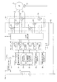
- FIG. 1 shows a configuration of an entire drive system which is housed within or attached to a housing body (not shown) of the electric power tool to be used for rotationally driving the rotational shaft.
- the electric power tool includes a three-phase brushless DC motor as a motor 20 which rotates the rotational shaft.
- the electric power tool also includes a battery pack 10, a motor drive circuit 24, a gate circuit 28, and a controller 40 as drive units that drive control the motor 20.
- the battery pack 10 is configured by housing a plurality of secondary battery cells connected in series inside a casing which can be detachably attached to the housing body of the electric power tool.
- the motor drive circuit 24 receives power supply from the battery pack 10 to flow an electric current to each phase winding of the motor 20.
- the motor drive circuit 24 includes six switching elements Q1 to Q6 constituted respectively of a FET.
- the switching elements Q1 to Q3 are provided as so-called high-side switches between each terminal U, V, W of the motor 20 and a power supply line connected to a positive electrode side of the battery pack 10.
- the switching elements Q4 to Q6 are provided as so-called low-side switches between the each terminal U, V, W of the motor 20 and a ground line connected to a negative electrode side of the battery pack 10.
- the gate circuit 28 in accordance with control signals outputted from the controller 40, turns on/off the switching elements Q1 to Q6 inside the motor drive circuit 24 to flow an electric current through each phase winding of the motor 20, thereby to rotate the motor 20.
- the controller 40 of the present embodiment is configured as a one-chip microcomputer which includes at least a CPU 401, a ROM 402, a RAM 403, an I/O port 404, an A/D converter 405, and a timer 406.
- the CPU 401 executes later-explained various processes according to various programs stored in the ROM 402.
- the controller 40 in accordance with a drive command from the trigger switch 30, sets a drive duty ratio of the switching elements Q1 to Q6 which constitute the motor drive circuit 24.
- the controller 40 outputs to the gate circuit 28 control signals in accordance with the drive duty ratio to rotationally drive the motor 20.
- the trigger switch 30 is a switch for inputting a command for driving the electric power tool.
- the trigger switch 30 is operated by a user of the electric power tool.
- the trigger switch 30 is provided in the housing body of the electric power tool together with a torque setting switch 36 and a torque setting indicator 38.
- the trigger switch 30 includes a main contact 31, a sliding resistor 32 and a forward reverse contact 33.
- the main contact 31 is a contact which is turned on when the trigger switch 30 is operated by a user.
- the sliding resistor 32 is a resistor of which resistance value varies in accordance with a pulling amount (i.e., amount of operation) of the trigger switch 30 by the user.
- the forward reverse contact 33 is a contact for receiving a command for switching a rotational direction from the user.
- the torque setting switch 36 is a switch for the user to set by manual operation an upper limit of rotational torque of the rotational shaft (for example, tightening torque by the tool bit).
- the torque setting switch 36 is connected to the controller 40.
- the torque setting indicator 38 is an indicator for displaying set torque which is set via the torque setting switch 36.
- the torque setting indicator 38 includes a plurality of LEDs, and is configured to display the set torque by the LEDs.
- the torque setting indicator 38 is also connected to the controller 40.
- the controller 40 controls the torque setting indicator 38 to cause the torque setting indicator 38 to display the set torque.
- the controller 40 controls a number of lighted LEDs or lighting patterns of the LEDs in the torque setting indicator 38, thereby causing the set torque to be displayed.
- the motor 20 includes a rotational position sensor 22 for detecting a rotational speed and a rotational position of the motor 20.
- a resistor 26 is provided for detecting a motor current flowing through the motor 20.
- a detection signal from the rotational position sensor 22 and a detection signal of the motor current from the resistor 26 are respectively inputted to the controller 40.
- a regulator 42 is provided inside the housing body of the electric power tool. The regulator 42 receives power supply from the battery pack 10 to generate the constant power supply voltage Vcc (for example, DC 5V) which is in turn supplied to the controller 40.
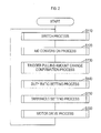
- the control process is a process repeatedly executed in the controller 40, when the power supply voltage Vcc is applied to the controller 40 from the regulator 42.
- the controller 40 when the control process is started, first executes a switch process in S110 (S represents a step).
- S represents a step
- a state of the main contact 31 of the trigger switch 30 and an operational state of the torque setting switch 36 are identified.
- the set torque is identified from the operational state of the torque setting switch 36 and displayed on the torque setting indicator 38.
- an initialization process is simultaneously performed in which various flags used for control are cleared and a current threshold which is an upper limit of the motor current is initialized to a value "0".
- an A/D conversion process is executed.
- a resistance value of the sliding resistor 32 of the trigger switch 30 and a voltage between both ends of the resistor 26 for detection of the motor current are retrieved via the A/D converter 405 inside the controller 40, so that the pulling amount of the trigger switch 30 (hereinafter referred to as a trigger pulling amount) and the motor current are identified.
- a trigger pulling amount change confirmation process shown in FIG. 3 is executed.
- a duty ratio setting process shown in FIG. 4 is executed.
- a threshold setting process shown in FIG. 5 is executed.
- a motor drive process shown in FIG. 6 is executed. After the motor drive process in S160 is executed, the process returns to S110.
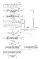
- the trigger pulling amount change confirmation process executed in S130 is a process for setting a correction value A used to update the current threshold when it is determined whether or not the trigger pulling amount identified in S120 has increased and that the trigger pulling amount has increased.
- the trigger pulling amount change confirmation process it is first determined in S210 whether or not the trigger pulling amount has increased. Unless the trigger pulling amount has increased, a value "0" is set as the correction value A of the current threshold in S220.
- the process proceeds to S230. It is then determined whether or not the increase is larger than a predetermined increase determination value. If the increase in the trigger pulling amount is not larger than the increase determination value, a preset predetermined value A1 is set as the correction value A of the current threshold in S240.
- the value A1 may be set as a constant value, or may be set as a larger value as the set torque is larger, in accordance with the set torque which is set via the torque setting switch 36. Then, when it is determined in S230 that the increase in the trigger pulling amount is larger than the predetermined increase determination value, a threshold subtraction flag is cleared in S250, a threshold constant flag is cleared in S260, and a value "0" is set as the correction value A of the current threshold in S270.
- the steps of S250 to S270 are processes for initializing each of the above flags and the correction value A, as a result of determination that the trigger switch 30 is re-operated by the user to input a command for driving when the increase in the trigger pulling amount is larger than the increase determination value.
- a fixed time counter is cleared which is used to count elapsed time from when the predetermined value A1 is set as the correction value A in S240. Then, the process proceeds to S330. When it is determined in S280 that the correction value A does not have a value "0", the process proceeds to S300. It is then determined based on a count value of the fixed time counter whether or not a certain period of time has elapsed from when the predetermined value A1 is set as the correction value A in S240.
- the trigger pulling amount this time is stored in the memory (RAM 403) inside the controller 40.
- the trigger pulling amount change confirmation process ends.
- the aforementioned duty ratio setting process executed in S140 is a process for setting an output duty ratio used to drive each of the switching elements Q1 to Q6 inside the motor drive circuit 24 via the gate circuit 28.
- a target duty ratio for controlling the rotational speed of the motor 20 to a rotational speed that corresponds to the trigger pulling amount is first set based on the trigger pulling amount in S410.
- an update process of the output duty ratio is executed.
- the output duty ratio is increased by adding a predetermined update value ⁇ to the present output duty ratio (initial value: 0).
- ⁇ a predetermined update value
- the target duty ratio is set in accordance with the trigger pulling amount. Then, the output duty ratio is gradually increased to the target duty ratio.
- the rotational speed of the motor 20 driven through the gate circuit 28 and the motor drive circuit 24 can be increased up to the rotational speed that corresponds to the trigger pulling amount, by the later described motor drive process.
- the aforementioned threshold setting process executed in S150 is a process for setting the current threshold.
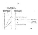
- the current threshold is set from start (time t0) of driving of the motor 20.
- a final value of the current threshold to limit the rotational torque of the rotational shaft to the set torque is set based on the set torque which is set via the torque setting switch 36 and a map shown in FIG. 8 .
- the final value of the current threshold is set to be larger, as the set torque is larger, based on the map shown in FIG. 8 , together with later described update values ⁇ and ⁇ . Subsequently, in S520, it is determined whether or not the threshold subtraction flag is cleared. If the threshold subtraction flag is cleared, the process proceeds to S530. By adding the update value ⁇ and the correction value A to the presently set current threshold (initial value: 0), the current threshold is updated (increased). The process proceeds to S600.
- the process proceeds to S550.
- the update value ⁇ that is set based on the map shown in FIG. 8 from the presently set current threshold and adding the correction value A, the current threshold is updated (decreased).
- the correction value A is set to the predetermined value A1 only for a certain period of time, when the pulling amount has increased in a rate of increase less than the increase determination value in the above described trigger pulling amount change confirmation process. Since a value "0" is set under otherwise conditions, the current threshold is normally updated using only the update value ⁇ or ⁇ in S530 and S550.
- update values ⁇ and ⁇ are not only set to be larger as the set torque is larger, based on the map shown in FIG. 8 as in the case with the final value of the current threshold, but are set in such a manner that a maximum value of the current threshold is sufficiently larger than the final value.
- the current threshold gradually increases by the update value ⁇ from start of driving of the motor 20 at time t0 until time t1 when the threshold subtraction flag is set, and then gradually decreases by the update value ⁇ .
- the current threshold takes the maximum value at time t1 when the threshold subtraction flag is set.
- the update values ⁇ and ⁇ which determine a rate of change per unit time of the current threshold are set such that the maximum value of the current threshold at time t1 is larger than the final value that corresponds to the set torque.
- the current threshold updated in S550 is compared with the final value of the current threshold set in S510 to determine whether or not the current threshold is equal to or lower than the final value. If the current threshold is equal to or lower than the final value, the final value is set as the current threshold in S570. After the threshold constant flag is set in S580, the process proceeds to S600. If the current threshold is not equal to or lower than the final value in S560, the process immediately proceeds to S600.
- the motor current detected through the resistor 26 is read. It is then determined whether or not the motor current has exceeded the current threshold. If the motor current has not exceeded the current threshold, the threshold setting process immediately ends.
- the threshold setting process immediately ends, since it is considered that, even if driving of the motor 20 continues, the rotational torque of the rotational shaft does not significantly increase.
- the aforementioned motor drive process executed in S160 is a process for rotationally driving the motor 20, by outputting to the gate circuit 28 control signals which correspond to the output duty ratio set in the aforementioned duty ratio setting process, when the trigger switch 30 is being operated by a user.
- the process proceeds to S730.
- the motor 20 is rotationally driven by outputting to the gate circuit 28 control signals which correspond to the output duty ratio set in the duty ratio setting process. Then, the motor drive process ends.
- a brake process is executed only for a certain period of time required for stopping the rotation of the motor 20, and then the motor drive process ends.
- generation of a drive force to make the motor 20 rotate is stopped and a braking force is generated in the motor 20 through the gate circuit 28 and the motor drive circuit 24..
- the current threshold which is the upper limit of the motor current is set. When the motor current exceeds the current threshold, driving of the motor 20 is stopped.
- limitation of the motor current by the current threshold is not performed after elapse of a certain period of time from start of driving of the motor 20 until the motor current is stabilized as before, but is performed immediately after start of driving of the motor 20.
- a back electromotive force generated in the motor 20 becomes substantially zero immediately after start of driving of the motor 20.
- the motor current increases as compared at normal driving of the motor 20. Because of this, when the current threshold immediately after start of driving of the motor 20 is set in accordance with the set torque, the motor current exceeds the current threshold immediately after start of driving of the motor 20. Then, driving of the motor 20 is stopped.
- the current threshold is increased in a constant slope which is determined by the update value ⁇ while the output duty ratio used for drive control of the motor 20 increases (that is, from time t0 until time t1) after start of driving of the motor 20.
- the current threshold is decreased in a constant slope which is determined by the update value ⁇ at time t1 and later.
- the current threshold is fixed to the final value.
- the electric power tool of the present embodiment on condition that an external load applied to the rotational shaft increases immediately after start of driving of the motor 20, for example, as in the case of retightening of screws, even if the trigger switch 30 is largely operated and the rotational torque of the rotational shaft exceeds the set torque, the increase in torque can be detected immediately using the current threshold and the motor current. Thereby, driving of the motor 20 can be stopped.
- the motor 20 (and a tool element mounted on the rotational shaft) can be driven more safely.
- the current threshold within the predetermined period of time from time t0 to t2 shown in FIG. 7 is set not in accordance with predetermined variation patterns but in accordance with changes in the output duty ratio used for electrical conduction control of the motor 20.
- changes in the trigger pulling amount is monitored which is the amount of operation of the trigger switch 30.
- the correction value A is added to the current threshold, so that the current threshold is temporarily increased.
- the motor current can be inhibited from exceeding the current threshold to stop driving of the motor 20.
- the resistor 26 corresponds to an example of a current detection unit of the present invention.
- the trigger switch 30 corresponds to an example of an operating portion of the present invention.
- the gate circuit 28 and the motor driving circuit 24 correspond to an example of a drive circuit of the present invention.
- the torque setting switch 36 corresponds to an example of a torque setting portion of the present invention.
- the controller 40 serves as an example of a current threshold setting unit, an example of a control unit, and an example of a duty ratio setting unit of the present invention.
- the function of the current threshold setting unit of the present invention is implemented by the threshold setting process executed in the controller 40
- the function of the duty ratio setting unit is implemented by the duty ratio setting process executed in the controller 40
- the function of the control unit is implemented by the motor drive process executed in the controller 40.
- the present invention is not limited to the above described embodiment, and can take various modes without departing from the spirit of the invention.
- the steps of S460 and S470 may be then executed, so that the rotational speed of the motor 20 may be controlled to a target rotational speed which corresponds to the trigger pulling amount.
- the process proceeds to S460 since the output duty ratio have reached the target duty ratio. Based on the trigger pulling amount, the target rotational speed of the motor 20 is set.
- the rotational speed of the motor 20 (and the rotational shaft) can be controlled to a constant speed which corresponds to the trigger pulling amount. Usability can be improved.
- the controller 40 is configured as a microcomputer, but may be configured as a programmable logic device such as, for example, ASIC (Application Specific Integrated Circuits), FPGA (Field Programmable Gate Array), and so on.
- ASIC Application Specific Integrated Circuits
- FPGA Field Programmable Gate Array
- control process executed by the controller 40 is implemented by executing a program by the CPU constituting the controller 40.
- This program may be written in a memory (such as a ROM 402) inside the controller 40, or may be recorded on a recording medium of which data can be read by the controller 40.
- a portable semiconductor memory for example, USB memory, memory card, etc.
- the motor 20 is described as a three-phase brushless DC motor.
- the motor 20 can be any motor as long as the motor can rotationally drive the rotational shaft which mounts a tool element.
Landscapes
- Engineering & Computer Science (AREA)
- Mechanical Engineering (AREA)
- Portable Power Tools In General (AREA)
- Details Of Spanners, Wrenches, And Screw Drivers And Accessories (AREA)
- Control Of Direct Current Motors (AREA)
- Control Of Electric Motors In General (AREA)
Applications Claiming Priority (1)
| Application Number | Priority Date | Filing Date | Title |
|---|---|---|---|
| JP2011189011A JP5726022B2 (ja) | 2011-08-31 | 2011-08-31 | 電動工具 |
Publications (3)
| Publication Number | Publication Date |
|---|---|
| EP2564984A2 true EP2564984A2 (de) | 2013-03-06 |
| EP2564984A3 EP2564984A3 (de) | 2015-12-02 |
| EP2564984B1 EP2564984B1 (de) | 2017-03-22 |
Family
ID=46800084
Family Applications (1)
| Application Number | Title | Priority Date | Filing Date |
|---|---|---|---|
| EP12182436.1A Not-in-force EP2564984B1 (de) | 2011-08-31 | 2012-08-30 | Elektrisches Werkzeug |
Country Status (5)
| Country | Link |
|---|---|
| US (1) | US9073186B2 (de) |
| EP (1) | EP2564984B1 (de) |
| JP (1) | JP5726022B2 (de) |
| CN (1) | CN102969974B (de) |
| RU (1) | RU2012137081A (de) |
Cited By (1)
| Publication number | Priority date | Publication date | Assignee | Title |
|---|---|---|---|---|
| TWI903109B (zh) * | 2022-09-06 | 2025-11-01 | 鑽全實業股份有限公司 | 電動工具及電動工具貼面停止控制方法 |
Families Citing this family (38)
| Publication number | Priority date | Publication date | Assignee | Title |
|---|---|---|---|---|
| US8269612B2 (en) | 2008-07-10 | 2012-09-18 | Black & Decker Inc. | Communication protocol for remotely controlled laser devices |
| US9908182B2 (en) | 2012-01-30 | 2018-03-06 | Black & Decker Inc. | Remote programming of a power tool |
| US8919456B2 (en) | 2012-06-08 | 2014-12-30 | Black & Decker Inc. | Fastener setting algorithm for drill driver |
| US20130327552A1 (en) | 2012-06-08 | 2013-12-12 | Black & Decker Inc. | Power tool having multiple operating modes |
| JP2014091167A (ja) * | 2012-10-31 | 2014-05-19 | Hitachi Koki Co Ltd | 電動工具 |
| CN104218868B (zh) * | 2013-05-30 | 2017-04-19 | 南京德朔实业有限公司 | 冲击类紧固工具转速控制方法 |
| JP6193673B2 (ja) * | 2013-08-07 | 2017-09-06 | 株式会社マキタ | 電動機械器具 |
| US10011006B2 (en) | 2013-08-08 | 2018-07-03 | Black & Decker Inc. | Fastener setting algorithm for drill driver |
| US20150306749A1 (en) * | 2014-04-28 | 2015-10-29 | Hsiu-Lin HSU | Energy-efficient electric screw drivers |
| CN105301987B (zh) * | 2014-05-28 | 2019-02-12 | 苏州宝时得电动工具有限公司 | 手持电动工具及其控制方法 |
| JP6489346B2 (ja) * | 2014-06-30 | 2019-03-27 | 工機ホールディングス株式会社 | 電動工具 |
| JP6282546B2 (ja) * | 2014-07-11 | 2018-02-21 | 株式会社マキタ | 電動工具 |
| CN104617853A (zh) * | 2014-10-28 | 2015-05-13 | 常州格力博有限公司 | 一种修枝机变速控制方法 |
| EP3296063B1 (de) * | 2016-06-24 | 2020-03-25 | Black & Decker Inc. | Steuerungsschema für ein elektrowerkzeug mit einem bürstenlosen motor |
| KR102437922B1 (ko) * | 2016-06-30 | 2022-08-29 | 아틀라스 콥코 인더스트리얼 테크니크 에이비 | 제어된 반작용력을 갖는 전기 펄스 공구 |
| CN106549574A (zh) * | 2016-11-25 | 2017-03-29 | 沈阳新阳光机电科技有限公司 | 大功率dcdc变换器系统及其控制方法 |
| CN108459519B (zh) * | 2017-02-22 | 2021-04-06 | 苏州宝时得电动工具有限公司 | 电动扳手控制方法及装置 |
| US11396092B2 (en) | 2017-06-16 | 2022-07-26 | Panasonic Intellectual Property Management Co., Ltd. | Electric power tool provided with motor controller controlling motor including limiter for limitting current contributing to torque generation |
| CN107565860B (zh) * | 2017-08-04 | 2020-10-02 | 九阳股份有限公司 | 一种豆浆机的电机启动方法 |
| EP3588524B1 (de) | 2018-06-28 | 2020-08-05 | Black & Decker Inc. | Elektronisches schaltmodul mit einer integrierten schutzdiode |
| CN109038902B (zh) * | 2018-07-03 | 2024-05-03 | 珠海格力节能环保制冷技术研究中心有限公司 | 一种设备控制方法、绕组切换器和电机 |
| JP2020035372A (ja) * | 2018-08-31 | 2020-03-05 | オムロン株式会社 | 情報処理装置及び情報処理方法 |
| JP6641607B2 (ja) * | 2018-12-28 | 2020-02-05 | 工機ホールディングス株式会社 | 電動工具 |
| CN111823193B (zh) * | 2019-04-19 | 2022-11-15 | 苏州宝时得电动工具有限公司 | 电动工具及其控制方法 |
| CN112140066B (zh) * | 2019-06-11 | 2024-04-09 | 苏州宝时得电动工具有限公司 | 一种电动工具 |
| KR102371991B1 (ko) * | 2019-12-12 | 2022-03-08 | 현대오토에버 주식회사 | 클러치 제어 시스템의 과전류 보호 장치 |
| JP6885455B2 (ja) * | 2019-12-27 | 2021-06-16 | 工機ホールディングス株式会社 | 電動工具 |
| US11919135B2 (en) | 2020-07-06 | 2024-03-05 | Milwaukee Electric Tool Corporation | Automatic ramp load sense for power tools |
| US12266918B2 (en) | 2022-09-20 | 2025-04-01 | Black & Decker Inc. | Constant-clutch operation at power tool start-up |
| EP3960371A1 (de) * | 2020-09-01 | 2022-03-02 | Hilti Aktiengesellschaft | Maschine und verfahren zum betreiben einer maschine |
| US11855567B2 (en) | 2020-12-18 | 2023-12-26 | Black & Decker Inc. | Impact tools and control modes |
| US11689124B2 (en) | 2021-01-12 | 2023-06-27 | Snap-On Incorporated | Controlling brushless motor commutation |
| CN115157182A (zh) * | 2021-04-07 | 2022-10-11 | 南京泉峰科技有限公司 | 电动工具 |
| US11973451B2 (en) | 2021-05-11 | 2024-04-30 | Black & Decker Inc. | Under-speed and closed-loop speed control in a variable-speed power tool |
| JP2023071389A (ja) * | 2021-11-11 | 2023-05-23 | 株式会社マキタ | 電動作業機 |
| CN115102460B (zh) * | 2022-05-24 | 2025-08-22 | 江苏东成工具科技有限公司 | 电动工具调速系统及方法 |
| JP2024059272A (ja) * | 2022-10-18 | 2024-05-01 | 株式会社マキタ | 電動工具、及び電動工具におけるモータの制御方法 |
| CN119713343A (zh) * | 2024-12-17 | 2025-03-28 | 广东澄一科技有限公司 | 一种开关面板驱动方法及吸油烟机 |
Citations (1)
| Publication number | Priority date | Publication date | Assignee | Title |
|---|---|---|---|---|
| JP2006281404A (ja) | 2005-04-04 | 2006-10-19 | Hitachi Koki Co Ltd | コードレス電動工具 |
Family Cites Families (7)
| Publication number | Priority date | Publication date | Assignee | Title |
|---|---|---|---|---|
| US6424799B1 (en) * | 1993-07-06 | 2002-07-23 | Black & Decker Inc. | Electrical power tool having a motor control circuit for providing control over the torque output of the power tool |
| JP4103505B2 (ja) * | 2002-08-29 | 2008-06-18 | トヨタ自動車株式会社 | 電気自動車およびこれに搭載された電動機の制御方法 |
| JP4339275B2 (ja) * | 2005-05-12 | 2009-10-07 | 株式会社エスティック | インパクト式のネジ締め装置の制御方法および装置 |
| JP2007015436A (ja) * | 2005-07-05 | 2007-01-25 | Asmo Co Ltd | 車両用乗降ステップ装置 |
| JP5242974B2 (ja) * | 2007-08-24 | 2013-07-24 | 株式会社マキタ | 電動工具 |
| JP5376392B2 (ja) * | 2008-02-14 | 2013-12-25 | 日立工機株式会社 | 電動工具 |
| JP5558125B2 (ja) * | 2010-01-28 | 2014-07-23 | 株式会社東芝 | モータの制御装置および制御方法 |
-
2011
- 2011-08-31 JP JP2011189011A patent/JP5726022B2/ja active Active
-
2012
- 2012-08-30 RU RU2012137081/02A patent/RU2012137081A/ru not_active Application Discontinuation
- 2012-08-30 EP EP12182436.1A patent/EP2564984B1/de not_active Not-in-force
- 2012-08-31 CN CN201210320328.2A patent/CN102969974B/zh not_active Expired - Fee Related
- 2012-08-31 US US13/601,185 patent/US9073186B2/en not_active Expired - Fee Related
Patent Citations (1)
| Publication number | Priority date | Publication date | Assignee | Title |
|---|---|---|---|---|
| JP2006281404A (ja) | 2005-04-04 | 2006-10-19 | Hitachi Koki Co Ltd | コードレス電動工具 |
Cited By (1)
| Publication number | Priority date | Publication date | Assignee | Title |
|---|---|---|---|---|
| TWI903109B (zh) * | 2022-09-06 | 2025-11-01 | 鑽全實業股份有限公司 | 電動工具及電動工具貼面停止控制方法 |
Also Published As
| Publication number | Publication date |
|---|---|
| JP2013049120A (ja) | 2013-03-14 |
| CN102969974A (zh) | 2013-03-13 |
| CN102969974B (zh) | 2015-09-09 |
| EP2564984B1 (de) | 2017-03-22 |
| US20130049643A1 (en) | 2013-02-28 |
| RU2012137081A (ru) | 2014-03-10 |
| EP2564984A3 (de) | 2015-12-02 |
| US9073186B2 (en) | 2015-07-07 |
| JP5726022B2 (ja) | 2015-05-27 |
Similar Documents
| Publication | Publication Date | Title |
|---|---|---|
| EP2564984B1 (de) | Elektrisches Werkzeug | |
| US8616299B2 (en) | Motor control device, electric power tool, and recording medium | |
| EP2572831B1 (de) | Elektrisches Werkzeug | |
| EP2574425B1 (de) | Elektrisches Werkzeug | |
| RU2588959C2 (ru) | Электроинструмент | |
| EP2853353B1 (de) | Elektrisches Werkzeug | |
| US10343268B2 (en) | Rotary impact tool | |
| CN101051744B (zh) | 电动工具机及用于运行该电动工具机的方法 | |
| EP2572832B1 (de) | Elektrowerkzeug, vorrichtung zur festlegung eines sperrstatus dafür und programm dafür | |
| EP2764956A1 (de) | Motorbetriebenes Gerät und Batteriepack | |
| CN103813887B (zh) | 电动工具 | |
| US8872451B2 (en) | Motor device and power tool | |
| CN104169050B (zh) | 电动工具 | |
| CN104159712B (zh) | 电动工具 | |
| CN115733393A (zh) | 电动作业机 | |
| JP2006247821A (ja) | 電動工具 | |
| EP2818281B1 (de) | Elektrowerkzeug | |
| US12308707B2 (en) | Electric work machine | |
| CN111379693A (zh) | 电动泵 | |
| JP2006000973A (ja) | 電池式電動工具 | |
| JP2002154064A (ja) | 半自動ねじ締結機に内装される電動モータの制御方法 |
Legal Events
| Date | Code | Title | Description |
|---|---|---|---|
| PUAI | Public reference made under article 153(3) epc to a published international application that has entered the european phase |
Free format text: ORIGINAL CODE: 0009012 |
|
| AK | Designated contracting states |
Kind code of ref document: A2 Designated state(s): AL AT BE BG CH CY CZ DE DK EE ES FI FR GB GR HR HU IE IS IT LI LT LU LV MC MK MT NL NO PL PT RO RS SE SI SK SM TR |
|
| AX | Request for extension of the european patent |
Extension state: BA ME |
|
| PUAL | Search report despatched |
Free format text: ORIGINAL CODE: 0009013 |
|
| AK | Designated contracting states |
Kind code of ref document: A3 Designated state(s): AL AT BE BG CH CY CZ DE DK EE ES FI FR GB GR HR HU IE IS IT LI LT LU LV MC MK MT NL NO PL PT RO RS SE SI SK SM TR |
|
| AX | Request for extension of the european patent |
Extension state: BA ME |
|
| RIC1 | Information provided on ipc code assigned before grant |
Ipc: B25B 21/00 20060101AFI20151029BHEP Ipc: B25B 23/147 20060101ALI20151029BHEP Ipc: B25F 5/00 20060101ALI20151029BHEP |
|
| 17P | Request for examination filed |
Effective date: 20160601 |
|
| RBV | Designated contracting states (corrected) |
Designated state(s): AL AT BE BG CH CY CZ DE DK EE ES FI FR GB GR HR HU IE IS IT LI LT LU LV MC MK MT NL NO PL PT RO RS SE SI SK SM TR |
|
| GRAP | Despatch of communication of intention to grant a patent |
Free format text: ORIGINAL CODE: EPIDOSNIGR1 |
|
| INTG | Intention to grant announced |
Effective date: 20161118 |
|
| GRAS | Grant fee paid |
Free format text: ORIGINAL CODE: EPIDOSNIGR3 |
|
| GRAA | (expected) grant |
Free format text: ORIGINAL CODE: 0009210 |
|
| AK | Designated contracting states |
Kind code of ref document: B1 Designated state(s): AL AT BE BG CH CY CZ DE DK EE ES FI FR GB GR HR HU IE IS IT LI LT LU LV MC MK MT NL NO PL PT RO RS SE SI SK SM TR |
|
| REG | Reference to a national code |
Ref country code: GB Ref legal event code: FG4D |
|
| REG | Reference to a national code |
Ref country code: CH Ref legal event code: EP |
|
| REG | Reference to a national code |
Ref country code: AT Ref legal event code: REF Ref document number: 877247 Country of ref document: AT Kind code of ref document: T Effective date: 20170415 |
|
| REG | Reference to a national code |
Ref country code: IE Ref legal event code: FG4D |
|
| REG | Reference to a national code |
Ref country code: DE Ref legal event code: R096 Ref document number: 602012030064 Country of ref document: DE |
|
| REG | Reference to a national code |
Ref country code: NL Ref legal event code: MP Effective date: 20170322 |
|
| PG25 | Lapsed in a contracting state [announced via postgrant information from national office to epo] |
Ref country code: NO Free format text: LAPSE BECAUSE OF FAILURE TO SUBMIT A TRANSLATION OF THE DESCRIPTION OR TO PAY THE FEE WITHIN THE PRESCRIBED TIME-LIMIT Effective date: 20170622 Ref country code: LT Free format text: LAPSE BECAUSE OF FAILURE TO SUBMIT A TRANSLATION OF THE DESCRIPTION OR TO PAY THE FEE WITHIN THE PRESCRIBED TIME-LIMIT Effective date: 20170322 Ref country code: FI Free format text: LAPSE BECAUSE OF FAILURE TO SUBMIT A TRANSLATION OF THE DESCRIPTION OR TO PAY THE FEE WITHIN THE PRESCRIBED TIME-LIMIT Effective date: 20170322 Ref country code: HR Free format text: LAPSE BECAUSE OF FAILURE TO SUBMIT A TRANSLATION OF THE DESCRIPTION OR TO PAY THE FEE WITHIN THE PRESCRIBED TIME-LIMIT Effective date: 20170322 Ref country code: GR Free format text: LAPSE BECAUSE OF FAILURE TO SUBMIT A TRANSLATION OF THE DESCRIPTION OR TO PAY THE FEE WITHIN THE PRESCRIBED TIME-LIMIT Effective date: 20170623 |
|
| REG | Reference to a national code |
Ref country code: LT Ref legal event code: MG4D |
|
| REG | Reference to a national code |
Ref country code: AT Ref legal event code: MK05 Ref document number: 877247 Country of ref document: AT Kind code of ref document: T Effective date: 20170322 |
|
| PG25 | Lapsed in a contracting state [announced via postgrant information from national office to epo] |
Ref country code: SE Free format text: LAPSE BECAUSE OF FAILURE TO SUBMIT A TRANSLATION OF THE DESCRIPTION OR TO PAY THE FEE WITHIN THE PRESCRIBED TIME-LIMIT Effective date: 20170322 Ref country code: RS Free format text: LAPSE BECAUSE OF FAILURE TO SUBMIT A TRANSLATION OF THE DESCRIPTION OR TO PAY THE FEE WITHIN THE PRESCRIBED TIME-LIMIT Effective date: 20170322 Ref country code: BG Free format text: LAPSE BECAUSE OF FAILURE TO SUBMIT A TRANSLATION OF THE DESCRIPTION OR TO PAY THE FEE WITHIN THE PRESCRIBED TIME-LIMIT Effective date: 20170622 Ref country code: LV Free format text: LAPSE BECAUSE OF FAILURE TO SUBMIT A TRANSLATION OF THE DESCRIPTION OR TO PAY THE FEE WITHIN THE PRESCRIBED TIME-LIMIT Effective date: 20170322 |
|
| PG25 | Lapsed in a contracting state [announced via postgrant information from national office to epo] |
Ref country code: NL Free format text: LAPSE BECAUSE OF FAILURE TO SUBMIT A TRANSLATION OF THE DESCRIPTION OR TO PAY THE FEE WITHIN THE PRESCRIBED TIME-LIMIT Effective date: 20170322 |
|
| PG25 | Lapsed in a contracting state [announced via postgrant information from national office to epo] |
Ref country code: IT Free format text: LAPSE BECAUSE OF FAILURE TO SUBMIT A TRANSLATION OF THE DESCRIPTION OR TO PAY THE FEE WITHIN THE PRESCRIBED TIME-LIMIT Effective date: 20170322 Ref country code: EE Free format text: LAPSE BECAUSE OF FAILURE TO SUBMIT A TRANSLATION OF THE DESCRIPTION OR TO PAY THE FEE WITHIN THE PRESCRIBED TIME-LIMIT Effective date: 20170322 Ref country code: SK Free format text: LAPSE BECAUSE OF FAILURE TO SUBMIT A TRANSLATION OF THE DESCRIPTION OR TO PAY THE FEE WITHIN THE PRESCRIBED TIME-LIMIT Effective date: 20170322 Ref country code: AT Free format text: LAPSE BECAUSE OF FAILURE TO SUBMIT A TRANSLATION OF THE DESCRIPTION OR TO PAY THE FEE WITHIN THE PRESCRIBED TIME-LIMIT Effective date: 20170322 Ref country code: RO Free format text: LAPSE BECAUSE OF FAILURE TO SUBMIT A TRANSLATION OF THE DESCRIPTION OR TO PAY THE FEE WITHIN THE PRESCRIBED TIME-LIMIT Effective date: 20170322 Ref country code: CZ Free format text: LAPSE BECAUSE OF FAILURE TO SUBMIT A TRANSLATION OF THE DESCRIPTION OR TO PAY THE FEE WITHIN THE PRESCRIBED TIME-LIMIT Effective date: 20170322 Ref country code: ES Free format text: LAPSE BECAUSE OF FAILURE TO SUBMIT A TRANSLATION OF THE DESCRIPTION OR TO PAY THE FEE WITHIN THE PRESCRIBED TIME-LIMIT Effective date: 20170322 |
|
| PG25 | Lapsed in a contracting state [announced via postgrant information from national office to epo] |
Ref country code: PT Free format text: LAPSE BECAUSE OF FAILURE TO SUBMIT A TRANSLATION OF THE DESCRIPTION OR TO PAY THE FEE WITHIN THE PRESCRIBED TIME-LIMIT Effective date: 20170724 Ref country code: IS Free format text: LAPSE BECAUSE OF FAILURE TO SUBMIT A TRANSLATION OF THE DESCRIPTION OR TO PAY THE FEE WITHIN THE PRESCRIBED TIME-LIMIT Effective date: 20170722 Ref country code: PL Free format text: LAPSE BECAUSE OF FAILURE TO SUBMIT A TRANSLATION OF THE DESCRIPTION OR TO PAY THE FEE WITHIN THE PRESCRIBED TIME-LIMIT Effective date: 20170322 Ref country code: SM Free format text: LAPSE BECAUSE OF FAILURE TO SUBMIT A TRANSLATION OF THE DESCRIPTION OR TO PAY THE FEE WITHIN THE PRESCRIBED TIME-LIMIT Effective date: 20170322 |
|
| REG | Reference to a national code |
Ref country code: DE Ref legal event code: R097 Ref document number: 602012030064 Country of ref document: DE |
|
| PLBE | No opposition filed within time limit |
Free format text: ORIGINAL CODE: 0009261 |
|
| STAA | Information on the status of an ep patent application or granted ep patent |
Free format text: STATUS: NO OPPOSITION FILED WITHIN TIME LIMIT |
|
| PG25 | Lapsed in a contracting state [announced via postgrant information from national office to epo] |
Ref country code: DK Free format text: LAPSE BECAUSE OF FAILURE TO SUBMIT A TRANSLATION OF THE DESCRIPTION OR TO PAY THE FEE WITHIN THE PRESCRIBED TIME-LIMIT Effective date: 20170322 |
|
| 26N | No opposition filed |
Effective date: 20180102 |
|
| PG25 | Lapsed in a contracting state [announced via postgrant information from national office to epo] |
Ref country code: SI Free format text: LAPSE BECAUSE OF FAILURE TO SUBMIT A TRANSLATION OF THE DESCRIPTION OR TO PAY THE FEE WITHIN THE PRESCRIBED TIME-LIMIT Effective date: 20170322 |
|
| REG | Reference to a national code |
Ref country code: CH Ref legal event code: PL |
|
| PG25 | Lapsed in a contracting state [announced via postgrant information from national office to epo] |
Ref country code: MC Free format text: LAPSE BECAUSE OF FAILURE TO SUBMIT A TRANSLATION OF THE DESCRIPTION OR TO PAY THE FEE WITHIN THE PRESCRIBED TIME-LIMIT Effective date: 20170322 |
|
| GBPC | Gb: european patent ceased through non-payment of renewal fee |
Effective date: 20170830 |
|
| PG25 | Lapsed in a contracting state [announced via postgrant information from national office to epo] |
Ref country code: CH Free format text: LAPSE BECAUSE OF NON-PAYMENT OF DUE FEES Effective date: 20170831 Ref country code: LI Free format text: LAPSE BECAUSE OF NON-PAYMENT OF DUE FEES Effective date: 20170831 |
|
| REG | Reference to a national code |
Ref country code: FR Ref legal event code: ST Effective date: 20180430 |
|
| REG | Reference to a national code |
Ref country code: IE Ref legal event code: MM4A |
|
| REG | Reference to a national code |
Ref country code: BE Ref legal event code: MM Effective date: 20170831 |
|
| PG25 | Lapsed in a contracting state [announced via postgrant information from national office to epo] |
Ref country code: LU Free format text: LAPSE BECAUSE OF NON-PAYMENT OF DUE FEES Effective date: 20170830 |
|
| PG25 | Lapsed in a contracting state [announced via postgrant information from national office to epo] |
Ref country code: GB Free format text: LAPSE BECAUSE OF NON-PAYMENT OF DUE FEES Effective date: 20170830 Ref country code: IE Free format text: LAPSE BECAUSE OF NON-PAYMENT OF DUE FEES Effective date: 20170830 |
|
| PG25 | Lapsed in a contracting state [announced via postgrant information from national office to epo] |
Ref country code: FR Free format text: LAPSE BECAUSE OF NON-PAYMENT OF DUE FEES Effective date: 20170831 Ref country code: BE Free format text: LAPSE BECAUSE OF NON-PAYMENT OF DUE FEES Effective date: 20170831 |
|
| PG25 | Lapsed in a contracting state [announced via postgrant information from national office to epo] |
Ref country code: MT Free format text: LAPSE BECAUSE OF NON-PAYMENT OF DUE FEES Effective date: 20170830 |
|
| PG25 | Lapsed in a contracting state [announced via postgrant information from national office to epo] |
Ref country code: HU Free format text: LAPSE BECAUSE OF FAILURE TO SUBMIT A TRANSLATION OF THE DESCRIPTION OR TO PAY THE FEE WITHIN THE PRESCRIBED TIME-LIMIT; INVALID AB INITIO Effective date: 20120830 |
|
| PG25 | Lapsed in a contracting state [announced via postgrant information from national office to epo] |
Ref country code: CY Free format text: LAPSE BECAUSE OF NON-PAYMENT OF DUE FEES Effective date: 20170322 |
|
| PGFP | Annual fee paid to national office [announced via postgrant information from national office to epo] |
Ref country code: DE Payment date: 20190820 Year of fee payment: 8 |
|
| PG25 | Lapsed in a contracting state [announced via postgrant information from national office to epo] |
Ref country code: MK Free format text: LAPSE BECAUSE OF FAILURE TO SUBMIT A TRANSLATION OF THE DESCRIPTION OR TO PAY THE FEE WITHIN THE PRESCRIBED TIME-LIMIT Effective date: 20170322 |
|
| PG25 | Lapsed in a contracting state [announced via postgrant information from national office to epo] |
Ref country code: TR Free format text: LAPSE BECAUSE OF FAILURE TO SUBMIT A TRANSLATION OF THE DESCRIPTION OR TO PAY THE FEE WITHIN THE PRESCRIBED TIME-LIMIT Effective date: 20170322 |
|
| PG25 | Lapsed in a contracting state [announced via postgrant information from national office to epo] |
Ref country code: AL Free format text: LAPSE BECAUSE OF FAILURE TO SUBMIT A TRANSLATION OF THE DESCRIPTION OR TO PAY THE FEE WITHIN THE PRESCRIBED TIME-LIMIT Effective date: 20170322 |
|
| REG | Reference to a national code |
Ref country code: DE Ref legal event code: R119 Ref document number: 602012030064 Country of ref document: DE |
|
| PG25 | Lapsed in a contracting state [announced via postgrant information from national office to epo] |
Ref country code: DE Free format text: LAPSE BECAUSE OF NON-PAYMENT OF DUE FEES Effective date: 20210302 |