EP2565079A2 - Fahrzeugleuchte - Google Patents
Fahrzeugleuchte Download PDFInfo
- Publication number
- EP2565079A2 EP2565079A2 EP20120182628 EP12182628A EP2565079A2 EP 2565079 A2 EP2565079 A2 EP 2565079A2 EP 20120182628 EP20120182628 EP 20120182628 EP 12182628 A EP12182628 A EP 12182628A EP 2565079 A2 EP2565079 A2 EP 2565079A2
- Authority
- EP
- European Patent Office
- Prior art keywords
- front cover
- vibrator
- electromagnetic vibrator
- lamp
- vehicle lamp
- Prior art date
- Legal status (The legal status is an assumption and is not a legal conclusion. Google has not performed a legal analysis and makes no representation as to the accuracy of the status listed.)
- Withdrawn
Links
- 239000012780 transparent material Substances 0.000 claims abstract description 4
- 230000002093 peripheral effect Effects 0.000 description 15
- 238000003780 insertion Methods 0.000 description 7
- 230000037431 insertion Effects 0.000 description 7
- 238000012423 maintenance Methods 0.000 description 5
- 239000000463 material Substances 0.000 description 4
- 230000002542 deteriorative effect Effects 0.000 description 3
- 239000011347 resin Substances 0.000 description 3
- 229920005989 resin Polymers 0.000 description 3
- 230000008901 benefit Effects 0.000 description 2
- 230000005540 biological transmission Effects 0.000 description 2
- 230000000694 effects Effects 0.000 description 2
- 239000000853 adhesive Substances 0.000 description 1
- 230000001070 adhesive effect Effects 0.000 description 1
- 238000000465 moulding Methods 0.000 description 1
- 230000003287 optical effect Effects 0.000 description 1
- 238000012856 packing Methods 0.000 description 1
- 229920000515 polycarbonate Polymers 0.000 description 1
- 239000004417 polycarbonate Substances 0.000 description 1
Images







Classifications
-
- B—PERFORMING OPERATIONS; TRANSPORTING
- B60—VEHICLES IN GENERAL
- B60Q—ARRANGEMENT OF SIGNALLING OR LIGHTING DEVICES, THE MOUNTING OR SUPPORTING THEREOF OR CIRCUITS THEREFOR, FOR VEHICLES IN GENERAL
- B60Q1/00—Arrangement of optical signalling or lighting devices, the mounting or supporting thereof or circuits therefor
- B60Q1/0017—Devices integrating an element dedicated to another function
-
- B—PERFORMING OPERATIONS; TRANSPORTING
- B60—VEHICLES IN GENERAL
- B60Q—ARRANGEMENT OF SIGNALLING OR LIGHTING DEVICES, THE MOUNTING OR SUPPORTING THEREOF OR CIRCUITS THEREFOR, FOR VEHICLES IN GENERAL
- B60Q5/00—Arrangement or adaptation of acoustic signal devices
- B60Q5/005—Arrangement or adaptation of acoustic signal devices automatically actuated
- B60Q5/008—Arrangement or adaptation of acoustic signal devices automatically actuated for signaling silent vehicles, e.g. for warning that a hybrid or electric vehicle is approaching
-
- G—PHYSICS
- G10—MUSICAL INSTRUMENTS; ACOUSTICS
- G10K—SOUND-PRODUCING DEVICES; METHODS OR DEVICES FOR PROTECTING AGAINST, OR FOR DAMPING, NOISE OR OTHER ACOUSTIC WAVES IN GENERAL; ACOUSTICS NOT OTHERWISE PROVIDED FOR
- G10K9/00—Devices in which sound is produced by vibrating a diaphragm or analogous element, e.g. fog horns, vehicle hooters or buzzers
- G10K9/12—Devices in which sound is produced by vibrating a diaphragm or analogous element, e.g. fog horns, vehicle hooters or buzzers electrically operated
- G10K9/13—Devices in which sound is produced by vibrating a diaphragm or analogous element, e.g. fog horns, vehicle hooters or buzzers electrically operated using electromagnetic driving means
-
- G—PHYSICS
- G10—MUSICAL INSTRUMENTS; ACOUSTICS
- G10K—SOUND-PRODUCING DEVICES; METHODS OR DEVICES FOR PROTECTING AGAINST, OR FOR DAMPING, NOISE OR OTHER ACOUSTIC WAVES IN GENERAL; ACOUSTICS NOT OTHERWISE PROVIDED FOR
- G10K9/00—Devices in which sound is produced by vibrating a diaphragm or analogous element, e.g. fog horns, vehicle hooters or buzzers
- G10K9/18—Details, e.g. bulbs, pumps, pistons, switches or casings
- G10K9/20—Sounding members
-
- G—PHYSICS
- G10—MUSICAL INSTRUMENTS; ACOUSTICS
- G10K—SOUND-PRODUCING DEVICES; METHODS OR DEVICES FOR PROTECTING AGAINST, OR FOR DAMPING, NOISE OR OTHER ACOUSTIC WAVES IN GENERAL; ACOUSTICS NOT OTHERWISE PROVIDED FOR
- G10K9/00—Devices in which sound is produced by vibrating a diaphragm or analogous element, e.g. fog horns, vehicle hooters or buzzers
- G10K9/18—Details, e.g. bulbs, pumps, pistons, switches or casings
- G10K9/22—Mountings; Casings
Definitions
- the present invention relates to a vehicle lamp that can sound an alarm to other vehicles and pedestrians.
- a motor In motor driven vehicles, such as hybrid vehicles and electric vehicles, a motor is quiet at low speed so that it is difficult to be perceived by other vehicles and pedestrians.
- a pseudo engine sound separately from the motor sound and to alert other vehicles and pedestrians using the pseudo engine sound.
- a related art vehicle lamp is configured such that a vibrator is provided on a headlight cover to vibrate the headlight cover, so that the headlight cover functions as a speaker (see, e.g., JP 2007-283809 A ).
- the vibrator is arranged at a position where the vibrator does not block a part of irradiation light emitted by a light source of the headlight and traveling through the headlight cover.
- the vibrator may be visible through the headlight cover when the headlight is viewed from the outside, in which case the external appearance of the headlight is deteriorated.
- attachment of the vibrator to the inner side of the headlight cover requires cumbersome steps during assembly. Further, because it is difficult to take the vibrator out of the headlight, it is disadvantageous in terms of maintenance.
- One or more embodiments of the present invention provide a vehicle lamp configured to generate a sound by vibrating the lamp without deteriorating the external appearance of the lamp.
- a vehicle lamp includes a light source, a front cover made of a transparent material to transmit light emitted by the light source, a lamp body forming a lamp housing together with the front cover, and a vibrator configured to vibrate the front cover to generate a vibration sound.
- the vibrator is supported by the lamp housing such that the vibrator contacts the front cover at a location where, when the vehicle lamp is mounted on a vehicle, the vibrator is not visible from an outside of the vehicle lamp.
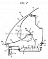
- Fig. 1 is a front view of a portion of a vehicle where a headlamp HL (an example of a vehicle lamp) according to one or more embodiments of the present invention is provided, and Fig. 2 is a longitudinal cross-sectional view taken along line II-II of Fig. 1 .
- a lamp housing 1 of the headlamp HL includes a lamp body 11 having a front opening and a front cover 12 attached to the lamp body 11 to cover the front opening of the lamp body 12.
- the lamp body 11 is configured to have a form of a container.
- the front cover 12 is made of a transparent resin.
- Lamp units 2, each including a light source, are installed inside the lamp housing 1.
- the lamp units 2 are arranged such that, when the lamp units 2 are turned on, light emitted by each of their light sources passes through the front cover 12.
- the headlamp HL is provided in an opening formed between a body panel B and a front bumper BP of the vehicle.
- the body panel B is, for example, a trunk lid or a fender.
- Fig. 2 illustrates one of the lamp units 2.
- the lamp unit 2 according to this illustrated example is a projector-type lamp unit.
- the lamp unit 2 includes an ellipsoidal reflector 22, a light source 21, e.g., a light-emitting diode (LED), provided at a location surrounded by the reflector 22, and a projection lens 23 configured to forwardly project light emitted by the LED 21 and reflected by the reflector 22.
- the LED 21, the reflector 22, and the projection lens 23 are provided on a base 24.
- An extension 13 is arranged inside the lamp housing 1 to conceal unnecessary area inside the lamp housing 1 from a front view of the headlamp HL, thereby improving an external appearance of the headlamp HL.
- the lower portion of the front cover 12 is extended down to the bottom of the lamp housing 1 so that it is not visible when the headlamp HL is viewed from the outside. That is, as illustrated in Fig. 1 , this extended portion 14 is covered and concealed by the extension 13 and the front bumper BP of the vehicle.
- the extended portion 14 has a shape of a flat plate.
- a vibrator 3 is attached to a rear surface of the extended portion 14, i.e., a portion of the inner surface of the front cover 12.
- the vibrator 3 is, but not limited to, an electromagnetic vibrator.
- the electromagnetic vibrator 3 vibrates by an electromagnetic action when current is applied. Along with its vibration, the electromagnetic vibrator 3 vibrates the extended portion 14 of the front cover 12 or the entire front cover 12 so that the front cover 12 functions as a sounding plate that generates an alarm sound.
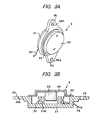
- the electromagnetic vibrator 3 includes a body 31 having a shape of a cylindrical container, a drive coil 32 wound around a cylindrical core 31a of the body 31, an annular spring plate 33 having an outer peripheral edge portion attached to an opening portion of the body 31, a vibrating plate 34 attached to an inner peripheral edge portion of the spring plate 33, and a columnar magnet 35 (a permanent magnet) attached to the inner surface of the vibrating plate 34 and partially disposed in a hollow portion of the cylindrical core 31a surrounded by the drive coil 32.
- the electromagnetic vibrator 3 also has tabs 36 protruding in the radial direction from two locations on the outer peripheral surface of the body 31. Each of the tabs 36 is formed with an insertion hole 36a into which a screw is inserted.
- a harness H3 is connected to the coil 32, and is led to the outside through the body 31.
- the magnet 35 When alternate current is applied to the drive coil 32 through the harness H3, the magnet 35 vibrates in the axial direction of the cylindrical core 31a by an alternating magnetic field generated by the drive coil 32 and a magnetic field of the magnet 35.
- the vibrating plate 34 to which the magnet 35 is attached, is vibrated accordingly in its thickness direction while flexing the spring plate 33. The vibration of the magnet 35 and the vibrating plate 34 is transmitted to the body 31.
- Fig. 4 is an enlarged view of a portion of Fig. 2 .
- the electromagnetic vibrator 3 is fixed to the inner surface of the extended portion 14 of the front cover 12 by screws 41 inserted into the insertion holes 36a of the tabs 36. Collars 42 having a suitable size are interposed between the tabs 36 and the extended portion 14, so that the front surface of the body 31 of the electromagnetic vibrator 3 firmly contacts the rear surface of the extended portion 14.
- the harness H3 connected to the electromagnetic vibrator 3 is electrically connected to a lamp control unit 5 inside the lamp housing 1.
- the lamp control unit 5 includes a sounding controller 51 and a lighting controller 52.
- the lamp control unit 5 is connected to a central control unit of the vehicle via a harness H1.
- the lighting controller 52 is connected to the lamp unit 2 via a harness H2 to control the lighting of the lamp unit 2.
- the sounding controller 51 is connected to the electromagnetic vibrator 3 via the harness H3 to control the sounding of the electromagnetic vibrator 3.
- the electromagnetic vibrator 3 When the electromagnetic vibrator 3 is driven by the sounding controller 51 of the lamp control unit 5, the magnet 35 and the vibrating plate 34 vibrate together, and this vibration is transmitted to the body 31. The vibration is further transmitted to substantially the entire portion of the front cover 12 from the extended portion 14, whereby the front cover 12 is vibrated to generate an alarm sound.
- the electromagnetic vibrator 3 When the headlamp HL is observed from the outside, the electromagnetic vibrator 3 is not visible through the front cover 12 because it is covered and concealed by the extension 13 and the bumper BP. Accordingly, the external appearance of the headlamp HL is not deteriorated by the vibrator 3.
- the location of the electromagnetic vibrator 3 is outside the optical path of the light from the lamp unit 2, so that the electromagnetic vibrator 3 does not affect the light distribution from the headlamp HL.
- the extended portion 14 of the front cover 12, to which the electromagnetic vibrator 3 is fixed is disposed outside of the lamp housing 1. Therefore, the electromagnetic vibrator 3 can be easily attached to or detached from the front cover 12. Accordingly, the electromagnetic vibrator 3 is easy to attach and to maintain.
- Fig. 5 is a cross-sectional view of a modified example of the first embodiment.
- the electromagnetic vibrator 3 is arranged to contact the front surface of the extended portion 14.
- Other features for fixing the electromagnetic vibrator 3 to the extended portion 14 are the same as the example shown in Fig. 4 . Accordingly, detailed description thereof will be omitted.
- the electromagnetic vibrator 3 is driven by the sounding controller 51 of the lamp control unit 5, the magnet 35 and the vibrating plate 34 vibrate together, and this vibration is transmitted to the body 31. The vibration is further transmitted to substantially the entire portion of the front cover 12 from the extended portion 14, whereby the front cover 12 is vibrated to generate an alarm sound.
- the electromagnetic vibrator 3 is still covered and concealed by the extension 13 and the bumper BP, so that it is not visible from the outside. Accordingly, the external appearance of the headlamp HL is not deteriorated.
- the extended portion 14 of the front cover 12 is extended to the outside of the lamp housing 1 and the electromagnetic vibrator 3 for attachment of the extended portion 14.
- the electromagnetic vibrator 3 may be provided inside the lamp housing 1.
- a lower peripheral portion 11a of the front opening of the lamp body 11 may be configured to extend downwards such that the extended portion 14 of the front cover 12 faces the lower peripheral portion 11a.
- Fig. 6 is an enlarged view of a portion of a second embodiment having such a structure.
- the configuration of the extended portion 14 of the front cover 12 is basically the same as the first embodiment, but it is different from the first embodiment in that the lower peripheral portion 11 a of the front opening of the lamp body 11 also extends downward along the extended portion 14.
- the lower peripheral portion 11a has a mounting hole 110, and a back cover 111 is detachably attached to the lower peripheral portion 11a to close the mounting hole 110.
- the back cover 111 is attached such that a flange edge 111a formed along the periphery of the back cover 111 is inserted into a recessed groove 11b provided on the lamp body 11.
- the mounting hole 110 is made watertight by a packing 114 provided in the recessed groove 11b.
- the electromagnetic vibrator 3 is fixed to the inner surface of the back cover 111.
- Bosses 112 are formed to protrude from the inner surface of the back cover 111.
- the electromagnetic vibrator 3 is fixed to the bosses 112 by screws 113 using the tabs 36 provided on the body 31 of the electromagnetic vibrator 3.
- Each of the bosses 112 is formed to have a suitable length so that a small gap is provided between the vibrating plate 34 of the electromagnetic vibrator 3 and the front surface of the back cover 111 to allow the vibration.
- the front surface of the body 31 firmly contacts the inner surface of the extended portion 14 of the front cover 12.
- the harness H3 extends inside the lamp housing I to electrically connect the electromagnetic vibrator 3 and the lamp control unit 5.
- the vibration of the magnet 35 and the vibrating plate 34 transmitted to substantially the entire portion of the front cover 12 via the body 31 and the extended portion 14, so that an alarm sound is generated.
- the vibration of the electromagnetic vibrator 3 is also transmitted to the lamp body 11 via the back cover 111 to generate an alarm sound. That is, substantially the entire headlamp HL is vibrated, so that a higher level of sound is generated.
- the electromagnetic vibrator 3 is not visible from the outside through the front cover 12, because it is concealed by the extension 13 and the bumper BP. Accordingly, the external appearance of the headlamp HL is not deteriorated.
- the electromagnetic vibrator 3 is mounted on the back cover 111, which is detachably attached to the lamp body 11, the electromagnetic vibrator 3 can be easily attached to or detached from the lamp housing 1. Accordingly, the electromagnetic vibrator 3 is easy to attach and to maintain. Furthermore, because the electromagnetic vibrator 3 is provided inside the lamp housing I, it is advantageous in that waterproofness of the electromagnetic vibrator 3 is significantly improved.
- the extended portion 14A is formed to rearwardly extend from the lower peripheral portion of the front cover 12 in a shape of a flat plate.
- the extended portion 14A is arranged in a region below the extension 13 and above the bottom wall of the lamp body 1 to extend along the bottom wall of the lamp body 11.
- the electromagnetic vibrator 3 may be supported on a back cover 111, detachably attached to the lamp body 11 to close a mounting hole 110 of the lamp body I I such that the electromagnetic vibrator 3 faces the extended portion 14A.
- the structure for supporting the electromagnetic vibrator 3 on the back cover 111 may be the same as that of the second embodiment illustrated in Fig. 6 .
- the body 31 of the electromagnetic vibrator 3 firmly contacts the extended portion 14A. Also with this configuration, the electromagnetic vibrator 3 is not visible from the outside through the front cover 12 by the extension 13 and the bumper BP, so that an alarm sound is generated without deteriorating the external appearance of the headlamp HL. Further, the electromagnetic vibrator 3 can be easily attached to or detached from the lamp housing 1. Accordingly, the maintenance of the electromagnetic vibrator 3 is also easy. Further, a portion of the extended portion 14A illustrated as a stippled region in Fig. 7 may be formed as an opaque cover that does not transmit light, so that the opaque extended portion 14A conceals the electromagnetic vibrator 3 when viewed from the outside through the front cover 12. In this case, a portion of the extension 13 above the extended portion 14A may be omitted.
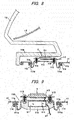
- the lower peripheral portion of the front cover 12 may be formed so as to be recessed rearward in a rectangular shape in a region below the extension 13, and the lower portion of this recessed lower peripheral portion may be formed as an extended portion 14B having a shape of a flat plate and extending rearward.
- a mounting hole 110 is formed through the lower wall of the lamp body 11 in a region facing the extended portion 14B, and a back cover 111 supporting the electromagnetic vibrator 3 is detachably provided to close the mounting hole 110.
- the structure for supporting the electromagnetic vibrator 3 on the back cover 111 may be the same as that of the third embodiment.
- the extended portion 14B is formed as an opaque cover that does not transmit light, as illustrated as a stippled region in Fig. 8 , so that the opaque extended portion 14B conceals the electromagnetic vibrator 3 when viewed from the outside through the front cover 12. Because the electromagnetic vibrator 3 is not visible from the outside through the front cover 12 by the extended portion 14B, an alarm sound can be generated by the electromagnetic vibrator 3 without deteriorating the external appearance of the headlamp HL. Further, the maintenance of the electromagnetic vibrator 3 is also easy.
- the sounding controller 51 for driving the electromagnetic vibrator 3 may be received and supported on the outer surface of a back cover 111.
- the sounding controller 51 including a circuit board is embedded inside a resin 115 to receive and support the sounding controller 51.
- the electromagnetic vibrator 3 is connected to the sounding controller 51 via a harness H3 passing through the back cover 111, and a harness H1 connected to the sounding controller 51 is led through the resin 115 and is electrically connected to the lamp control unit 5 or a central control unit of a vehicle.
- the sounding device can be provided separately from the lamp control unit 5. Therefore, the lamp control unit 5 can be simplified, and the lamp control unit 5 can be configured for more general purpose. Accordingly, the vibrator 3 can be provided as an option for a vehicle that does not initially have a vibrator or other sounding device for sounding an alarm.
- Fig. 10 is a cross-sectional view of a headlamp HL according to a fifth embodiment, where it is difficult to form an extended portion of a front cover 12 due to design constraint, such as a limitation on the size of the headlamp HL.
- an electromagnetic vibrator 3 may be fixed to an inner surface of a portion of the front cover 12 which, when mounted on a vehicle, is concealed by the bumper BP and the extension 13 so that it is not visible from the outside.
- the front cover 12 is often three-dimensionally curved so as to conform to the shape of a vehicle body, and it is difficult to bring the flat front surface of the body 31 of the electromagnetic vibrator 3 in firm contact with the inner surface of the front cover 12 if the electromagnetic vibrator 3 is directly fixed to the inner surface of the curved front cover 12. And if the front surface of the body 31 of the electromagnetic vibrator 3 does not firmly contact the inner surface of the front cover 12, the vibration of the electromagnetic vibrator 3 may not be efficiently transmitted to the front cover 12 and may lower sounding efficiency. For example, if the front cover 12 is sloped, only a portion of the circumference of the body 31 of the electromagnetic vibrator 3 may contact the inner surface of the front cover 12.
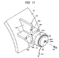
- a fastening seat 15 is integrally molded on a curved inner surface of the front cover 12 to extend inward therefrom, and the electromagnetic vibrator 3 is secured to the fastening seat 15.
- Fig. 11 is a perspective view of the fastening seat 15, and Fig. 12 is a cross-sectional view illustrating a state in which the electromagnetic vibrator 3 is fixed to the fastening seat 15.
- the fastening seat 15 includes cross-shaped walls 151 extending from a portion of the inner surface of the front cover 12.
- the cross-shaped walls 151 have a crossed shape when viewed from the inner side, and the top surfaces (the rear surfaces) of the cross-shaped walls 151 are formed flat.
- the peripheral portions of the top surfaces of the cross-shaped walls 151 are formed higher than the central portions, and stepped portions 152 are provided between the peripheral portions and the central portions.
- the outer peripheral wall of the electromagnetic vibrator 3 is positioned by the stepped portions 152.
- a screw hole 153 is formed at the center of the top surfaces of the cross-shaped walls 151, and a rotation preventing hole 154 is formed on the top surface of one of the walls 151.
- the electromagnetic vibrator 3 according to this example has almost the same structure as the electromagnetic vibrators 3 of the first to fourth embodiments.
- the electromagnetic vibrator 3 of this example includes a hollow cylindrical magnet 35, and a vibrating plate 34 having a screw insertion hole 34a concentric with a center hole 35a of the magnet 35.
- the tabs 36 illustrated in the first to fourth embodiments are not provided.
- a screw 43 (an example of a fastener) is inserted into the screw insertion hole 34a, and is screwed into the screw hole 153 of the top surfaces of the cross-shaped walls 151 after passing through a fastening hole 31c of the body 31, so that the electromagnetic vibrator 3 is fixed to the fastening seat 15 by the screw 43.
- a rotation preventing protrusion 31b formed on a portion of the front surface of the body 31 of the electromagnetic vibrator 3 is fitted into the rotation preventing hole 154 of the wall 151, so that the electromagnetic vibrator 3 is not rotated.
- the electromagnetic vibrator 3 is fixed to the curved inner surface of the front cover 12, but the electromagnetic vibrator 3 and the front cover 12 firmly contact with each other by the fastening seat 15. Accordingly, the vibration of the electromagnetic vibrator 3 is efficiently transmitted to the front cover 12 to increase a sounding effect. Further, the electromagnetic vibrator 3 is fastened to the fastening seat 15 by one screw 43 inserted into the opening of the electromagnetic vibrator 3, i.e., the center hole 35a of the magnet, the screw insertion hole 34a, and the fastening hole 31 c. Thus, cost reduction is achieved by improving the work for fixing the electromagnetic vibrator 3 and by reducing the number of components. Furthermore, as shown in Fig.
- the mounting hole 110 is formed through the back wall of the lamp body 11 and the detachable back cover 111 is provided to close the mounting hole 110.
- the electromagnetic vibrator 3 can be attached or detached by removing the back cover 111, so that the maintenance of the electromagnetic vibrator 3 is easy.
- the electromagnetic vibrator 3 is not visible from the outside through the front cover 12 by the extension 13 and the bumper BP, the external appearance of the headlamp HL is not deteriorated.
- the screw insertion hole 35a is formed through the center of the magnet 35. Accordingly, a rotationally symmetric magnetic field is generated, whereby the magnet 35 is vibrated uniformly, and the vibrating plate 34 is also vibrated uniformly.
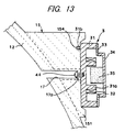
- a recessed hole 17 may be formed toward the top surface of the fastening seat 15 from the front surface side of the front cover 12 as shown in Fig. 13 , and a screw 44 (another example of a faterner) may be inserted into a screw insertion hole 17a formed at the bottom of the recessed hole 17 and screwed into the body 31 of the electromagnetic vibrator 3 from the front surface side to fix the electromagnetic vibrator 3 to the fastening seat 15.
- the magnet 35 does not need to be formed in a hollow cylindrical shape having the center hole 35a. Therefore, an electromagnetic vibrator having a more general configuration, like those in the first to fourth embodiments, can be used.
- a screw 43, 44 made of the same material as the front cover 12 or a material similar to the material of the front cover 12.
- the front cover 12 and the screw 43, 44 may both be made of polycarbonate. In this way, the screw 43, 44 and the front cover 12 have the same resonant frequency, so that the efficiency of the transmission of vibration from the electromagnetic vibrator 3 to the front cover 12 is increased.
- the electromagnetic vibrator 3 is brought into firm surface contact with the inner surface of the front cover 12.
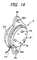
- a plurality of protrusions here, three protrusions 16, are provided at three locations on the surface of a body 31 of an electromagnetic vibrator 3 along a circumferential direction.
- each of the protrusions 16 has a shape like a hemisphere, and they all have the same height.
- the protrusions 16 are provided in the region where the amplitude of the vibration generated in the body 31 becomes as large as possible. It is advantageous to form the protrusions 16 and the body 31 in a one-piece structure, but the protrusions 16 may be formed separately from the body31 and may be joined to the body 31 by means of adhesive or the like.
- the electromagnetic vibrator 3 is fixed by screws 113 using boss portions 12a formed on a portion of the front cover 12 that is not visible from the outside when installed in a vehicle. It is advantageous to provide washers 37 made of a cushioning material, such as rubber, between the electromagnetic vibrator 3 and each of the boss portions 12a. By attaching the electromagnetic vibrator 3 to the front cover 12 in this way, even when the inner surface of the front cover 12 is not flat, e.g., when it is curved, the washers 37 are elastically deformed in accordance with the fastening of the screws 113, and the electromagnetic vibrator 3 arranged in an inclined manner so as to correspond to the inner surface of the front cover 12.
- the ends of the respective protrusions 16 of the electromagnetic vibrator 3 contact the inner surface of the front cover 12. That is, the body 31 of the electromagnetic vibrator 3 is fixed to the inner surface of the front cover such that the electromagnetic vibrator 3 reliably contacts the inner surface of the front cover 12 at the protrusions 16, whereby vibration is effectively transmitted to the front cover 12 of the electromagnetic vibrator 3. Even when the inner surface of the front cover 12 is a wavy surface, a surface having a complicated shape, such as partially inclined surface, or a coarse surface, the protrusions 16 can reliably contact the inner surface.
- the protrusions 16 may be formed to have different heights so as to correspond to the condition of the inner surface. Further, the number of the protrusions 16 does not necessarily need to be three, and may be two or one. In any case, even when the electromagnetic vibrator 3 is arranged in an inclined manner, the electromagnetic vibrator 3 and the front cover 12 can be reliably brought into contact with each other at the protrusions 16. In addition, the protrusions 16 are provided at locations where the amplitude of vibration of the body 31 of the electromagnetic vibrator 3 is large. Thus, it is possible to effectively transmit the vibration of the electromagnetic vibrator 3 to the front cover 12 and to increase the sounding effect of the front cover 12, as compared to a case where only one side of the body 31 of the electromagnetic vibrator 3 contacts the inner surface of the front cover 12.
- the protrusions 16A between the electromagnetic vibrator 3 and the front cover 12 may be formed on the inner surface of the front cover 12.
- the front cover 12 is made of a transparent material and is usually formed by die molding. Therefore, the protrusion 16A can be easily formed integrally with the front cover 12.
- the heights of one to three protrusions 16A are designed in accordance with the condition of the curvature or inclination of the inner surface of the front cover 12, so that the ends of the three protrusions 16A reliably contacts the surface of the electromagnetic vibrator 3.
- protrusions 16A When providing three protrusions 16A, they can be designed such that a plane formed by connecting the ends of the protrusions 16A is oriented in a desired direction, and boss portions 12a for fixing the electromagnetic vibrator 3 may also be formed so as to have heights corresponding to the plane. In this case, the electromagnetic vibrator 3 is fixed to the boss portions 12a such that the surface of the electromagnetic vibrator 3 contacts the protrusions 16A. Therefore, cushioning washers 37 are not needed. Further, by providing the protrusions 16A on the front cover 12, the electromagnetic vibrator in the first to fourth embodiments can be used without modifying the electromagnetic vibrator 3.
- Figs. 17A and 17B are cross-sectional views according to a seventh embodiment.
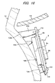
- an extended portion 14 having a shape of a flat plate is provided at the lower peripheral portion of a front cover 12 to extend in a vertical direction, and an electromagnetic vibrator 3 is brought into elastic contact with the inner surface of the extended portion 14 by an elastic force.
- Fig. 17A is a view illustrating a state where the front cover 12 is not yet attached a lamp body 1.
- a support frame 17 is provided on the lower inner surface of the lamp body 11 at a location corresponding to the extended portion 14 of the front cover 12, and an end portion of a lower side 45a of a L-shaped spring plate 45 (an example of a resilient member) is fitted to and supported by the support frame 17.
- the electromagnetic vibrator 3 is fixed to and supported by an upper side 45b of the spring plate 45.
- Tabs 36 of the electromagnetic vibrator 3 may be used to fix the electromagnetic vibrator 3, as in the first to fourth embodiments and the sixth embodiment.
- an angle between the lower side 45a and the upper side 45b of the spring plate 45 is larger than 90°, and the electromagnetic vibrator 3 is disposed at a position more forward than the front opening of the lamp body 11.
- the front cover 12 When the front cover 12 is mounted on the lamp body 11 as shown in Fig. 17B , the front surface of the body 31 contacts the inner surface of the extended portion 14 of the front cover 12, and the electromagnetic vibrator 3 is moved rearward. Because the upper side 45b of the spring plate 45 is elastically deformed rearward, the electromagnetic vibrator 3 is pushed forward by an elastic repulsive force of the spring plate 45, and is brought into elastic contact with the inner surface of the extended portion 14. Accordingly, the electromagnetic vibrator 3 firmly contacts the inner surface of the extended portion 14, the vibration of the electromagnetic vibrator 3 is efficiency transmitted to the extended portion 14 to generate a sound by the front cover 12.
- the angle between the lower side 45a and the upper side 45b of the spring plate 45 may be smaller than 90°. Also when the angle between the lower side 45a and the upper side 45b of the spring plate 45 is smaller than 90°, the spring plate 45 is arranged such that the upper side 45b is inclined toward the front cover 12 before attaching the front cover 12.
- the electromagnetic vibrator 3 can be attached and detached using the back cover 111 provided on the back surface of the lamp body 11, as in the fifth and sixth embodiments. Accordingly, the maintenance of the electromagnetic vibrator 3 is easy.
- a fastening seat 15 having a flat top surface may be provided integrally with the front cover 12 as in the fifth embodiment so that the electromagnetic vibrator 3 can elastically contact the fastening seat 15.
- one to three protrusions 16, 16A may be formed on the surface of the body 31 of the electromagnetic vibrator 3 or the inner surface of the front cover 12, so that the surface of the electromagnetic vibrator 3 elastically contacts the inner surface of the front cover 12 at the protrusions. In any case, even when the inner surface of the front cover 12 is curved, it is possible to make the surface of the electromagnetic vibrator 3 reliably contact the inner surface of the front cover 12 to generate a sound by effectively vibrating the front cover 12.
- the transparent front cover may be a lens that refracts light emitted by the light source.
Landscapes
- Physics & Mathematics (AREA)
- Engineering & Computer Science (AREA)
- Acoustics & Sound (AREA)
- Multimedia (AREA)
- Mechanical Engineering (AREA)
- Electromagnetism (AREA)
- Lighting Device Outwards From Vehicle And Optical Signal (AREA)
- Non-Portable Lighting Devices Or Systems Thereof (AREA)
Applications Claiming Priority (2)
| Application Number | Priority Date | Filing Date | Title |
|---|---|---|---|
| JP2011191262 | 2011-09-02 | ||
| JP2012108985A JP5977575B2 (ja) | 2011-09-02 | 2012-05-11 | 車両用ランプ |
Publications (2)
| Publication Number | Publication Date |
|---|---|
| EP2565079A2 true EP2565079A2 (de) | 2013-03-06 |
| EP2565079A3 EP2565079A3 (de) | 2014-08-13 |
Family
ID=46762927
Family Applications (1)
| Application Number | Title | Priority Date | Filing Date |
|---|---|---|---|
| EP20120182628 Withdrawn EP2565079A3 (de) | 2011-09-02 | 2012-08-31 | Fahrzeugleuchte |
Country Status (4)
| Country | Link |
|---|---|
| US (1) | US9120418B2 (de) |
| EP (1) | EP2565079A3 (de) |
| JP (1) | JP5977575B2 (de) |
| CN (1) | CN102975651B (de) |
Cited By (8)
| Publication number | Priority date | Publication date | Assignee | Title |
|---|---|---|---|---|
| DE102012111352A1 (de) * | 2012-11-23 | 2014-05-28 | Dr. Ing. H.C. F. Porsche Aktiengesellschaft | Kraftfahrzeug |
| WO2015024815A3 (de) * | 2013-08-19 | 2015-04-16 | Hella Kgaa Hueck & Co. | Beleuchtungseinrichtung für ein fahrzeug mit einem schmutzsensor |
| WO2016000866A1 (de) * | 2014-07-03 | 2016-01-07 | Volkswagen Aktiengesellschaft | Montageverbund einer kraftfahrzeug-beleuchtungseinrichtung |
| DE102014222033A1 (de) * | 2014-10-29 | 2016-05-04 | Bayerische Motoren Werke Aktiengesellschaft | Baugruppe mit einem Signalhorngehäuse und Frontendmodul |
| FR3088599A1 (fr) * | 2018-11-15 | 2020-05-22 | Psa Automobiles Sa | Support de montage d'un dispositif d'alarme sonore d'un avas sur la caisse d'un vehicule automobile silencieux |
| CN113677561A (zh) * | 2019-03-29 | 2021-11-19 | 标致雪铁龙汽车股份有限公司 | 将装配在共同支撑件上的发光照射灯和保险杠均衡地装配在机动车辆车身上的装置和方法 |
| EP4549251A1 (de) * | 2023-11-03 | 2025-05-07 | HELLA Saturnus Slovenija d.o.o. | Fahrzeugkarosserieplattenanordnung mit integrierten funktionskomponenten |
| US12480652B1 (en) * | 2024-05-24 | 2025-11-25 | Hyundai Mobis Co., Ltd. | Lamp for vehicle, vehicle, and method of operating lamp for vehicle |
Families Citing this family (12)
| Publication number | Priority date | Publication date | Assignee | Title |
|---|---|---|---|---|
| TWI665405B (zh) * | 2018-12-19 | 2019-07-11 | 福安工業股份有限公司 | 車燈透鏡組配裝置 |
| DE102019106748A1 (de) * | 2019-03-18 | 2020-09-24 | Webasto SE | Verfahren zur Verwendung eines zum Antrieb einer Fahrzeugdach-Komponente genutzten Elektromotors zur Schallerzeugung |
| US12055626B2 (en) * | 2019-08-05 | 2024-08-06 | Koito Manufacturing Co., Ltd. | Vehicle lamp and vehicle |
| KR102821814B1 (ko) * | 2020-02-19 | 2025-06-17 | 현대자동차주식회사 | 차량 및 그 제어 방법 |
| KR20230108822A (ko) * | 2022-01-12 | 2023-07-19 | 현대모비스 주식회사 | 차량용 램프 |
| KR20230168421A (ko) * | 2022-06-07 | 2023-12-14 | 현대모비스 주식회사 | 사운드 출력이 가능한 자동차용 램프 및 이를 이용한 커뮤니케이션 시스템 |
| JP7708078B2 (ja) * | 2022-11-17 | 2025-07-15 | トヨタ自動車株式会社 | 車両前部構造 |
| JP2024085696A (ja) * | 2022-12-15 | 2024-06-27 | 豊田合成株式会社 | 車両の音出力装置 |
| WO2024204109A1 (ja) * | 2023-03-28 | 2024-10-03 | 株式会社小糸製作所 | 車両用灯具及び音発生ユニット |
| KR20260023896A (ko) * | 2024-08-12 | 2026-02-20 | 현대모비스 주식회사 | 차량용 램프 |
| KR20260023897A (ko) * | 2024-08-12 | 2026-02-20 | 현대모비스 주식회사 | 차량용 램프 |
| US12449109B1 (en) | 2024-11-14 | 2025-10-21 | Ford Global Technologies, Llc | Vehicle vent patch systems with ultrasonic devices |
Citations (1)
| Publication number | Priority date | Publication date | Assignee | Title |
|---|---|---|---|---|
| JP2007283809A (ja) | 2006-04-13 | 2007-11-01 | Anden | 車両周辺に対して警報を発する警報音発生装置 |
Family Cites Families (22)
| Publication number | Priority date | Publication date | Assignee | Title |
|---|---|---|---|---|
| US1958028A (en) * | 1933-02-15 | 1934-05-08 | Eugene F Aymar | Signal device |
| US2632154A (en) * | 1951-08-20 | 1953-03-17 | Harry E Pouell | Audible signal attachment for motor vehicle backing lights |
| US4184102A (en) * | 1978-05-05 | 1980-01-15 | Nippon Lissajou Co., Ltd. | Flashing and sound generating lamp |
| JPS59110246U (ja) * | 1983-01-11 | 1984-07-25 | 株式会社東海理化電機製作所 | 車両用後方警報装置 |
| JPH0249606Y2 (de) * | 1986-07-04 | 1990-12-27 | ||
| JPS63133797U (de) * | 1987-02-23 | 1988-09-01 | ||
| JPS63151336U (de) * | 1987-03-27 | 1988-10-05 | ||
| US4903007A (en) * | 1988-07-22 | 1990-02-20 | Design Tech International, Inc. | Combination back-up light and sound emitting device for automotive vehicle |
| US4851813A (en) * | 1988-07-22 | 1989-07-25 | Design Tech International, Inc. | Combination back-up light and sound emitting device for automotive vehicle |
| US5047747A (en) * | 1990-07-25 | 1991-09-10 | Designtech International, Inc | Combination back-up light and sound emitting device for trucks and other automotive vehicles |
| US5546284A (en) * | 1994-04-19 | 1996-08-13 | Koito Manufacturing Co., Ltd. | Automobile headlamp with extension reflector mounted on the front lense |
| JP3225005B2 (ja) * | 1997-06-17 | 2001-11-05 | 株式会社小糸製作所 | 車輌用灯具 |
| US6028511A (en) * | 1998-09-15 | 2000-02-22 | Preco New Products Corp. | Light activated back-up alarm |
| JP2000195309A (ja) * | 1998-12-25 | 2000-07-14 | Koito Mfg Co Ltd | 車両用標識灯 |
| US6154125A (en) * | 1999-12-01 | 2000-11-28 | Robert S. Berkowitz | Audible pedestrian turn signal alert system |
| US6977584B2 (en) * | 2000-02-28 | 2005-12-20 | Milliken Franklin L | Vehicle back up alarm with associated back up light |
| CN2527858Y (zh) * | 2002-02-04 | 2002-12-25 | 陈凯柏 | 具有警示发声器的led灯泡 |
| JP3931092B2 (ja) * | 2002-02-08 | 2007-06-13 | 株式会社小糸製作所 | 車輌用前照灯 |
| JP4070190B2 (ja) * | 2002-08-19 | 2008-04-02 | 株式会社小糸製作所 | 車両用ヘッドランプ |
| CN100355617C (zh) * | 2003-05-20 | 2007-12-19 | 雅马哈发动机株式会社 | 机动二轮车 |
| US20100141419A1 (en) * | 2008-12-04 | 2010-06-10 | Coward Mark T | Combined Backup Alarm and Reversing Lamp |
| US8669852B2 (en) * | 2009-11-05 | 2014-03-11 | Star Headlight & Lantern Co., Inc. | Acoustic backup alarm for providing acoustic and dual technology (acoustical and optical) operation |
-
2012
- 2012-05-11 JP JP2012108985A patent/JP5977575B2/ja not_active Expired - Fee Related
- 2012-08-31 EP EP20120182628 patent/EP2565079A3/de not_active Withdrawn
- 2012-09-03 CN CN201210321308.7A patent/CN102975651B/zh not_active Expired - Fee Related
- 2012-09-04 US US13/602,647 patent/US9120418B2/en not_active Expired - Fee Related
Patent Citations (1)
| Publication number | Priority date | Publication date | Assignee | Title |
|---|---|---|---|---|
| JP2007283809A (ja) | 2006-04-13 | 2007-11-01 | Anden | 車両周辺に対して警報を発する警報音発生装置 |
Cited By (16)
| Publication number | Priority date | Publication date | Assignee | Title |
|---|---|---|---|---|
| US9121560B2 (en) | 2012-11-23 | 2015-09-01 | Dr. Ing. H.C. F. Porsche Aktiengesellschaft | Motor vehicle |
| DE102012111352A1 (de) * | 2012-11-23 | 2014-05-28 | Dr. Ing. H.C. F. Porsche Aktiengesellschaft | Kraftfahrzeug |
| DE102012111352B4 (de) | 2012-11-23 | 2024-05-16 | Dr. Ing. H.C. F. Porsche Aktiengesellschaft | Kraftfahrzeug und Verfahren zum Betreiben eines Kraftfahrzeugs |
| DE102013108911B4 (de) | 2013-08-19 | 2022-12-08 | HELLA GmbH & Co. KGaA | Beleuchtungseinrichtung für ein Fahrzeug mit einem Schmutzsensor |
| WO2015024815A3 (de) * | 2013-08-19 | 2015-04-16 | Hella Kgaa Hueck & Co. | Beleuchtungseinrichtung für ein fahrzeug mit einem schmutzsensor |
| WO2016000866A1 (de) * | 2014-07-03 | 2016-01-07 | Volkswagen Aktiengesellschaft | Montageverbund einer kraftfahrzeug-beleuchtungseinrichtung |
| CN106660481A (zh) * | 2014-07-03 | 2017-05-10 | 大众汽车有限公司 | 机动车辆照明设备的装配组件 |
| EP4183627A1 (de) * | 2014-07-03 | 2023-05-24 | Volkswagen Aktiengesellschaft | Montageverbund einer kraftfahrzeug-beleuchtungseinrichtung und kraftfahrzeug |
| DE102014222033A1 (de) * | 2014-10-29 | 2016-05-04 | Bayerische Motoren Werke Aktiengesellschaft | Baugruppe mit einem Signalhorngehäuse und Frontendmodul |
| WO2020099759A1 (fr) * | 2018-11-15 | 2020-05-22 | Psa Automobiles Sa | Support de montage d'un dispositif d'alarme sonore d'un avas sur la caisse d'un véhicule automobile silencieux |
| FR3088599A1 (fr) * | 2018-11-15 | 2020-05-22 | Psa Automobiles Sa | Support de montage d'un dispositif d'alarme sonore d'un avas sur la caisse d'un vehicule automobile silencieux |
| CN113677561A (zh) * | 2019-03-29 | 2021-11-19 | 标致雪铁龙汽车股份有限公司 | 将装配在共同支撑件上的发光照射灯和保险杠均衡地装配在机动车辆车身上的装置和方法 |
| CN113677561B (zh) * | 2019-03-29 | 2024-03-01 | 标致雪铁龙汽车股份有限公司 | 将部件组件均衡地装配在机动车辆车身上的装置和方法 |
| EP4549251A1 (de) * | 2023-11-03 | 2025-05-07 | HELLA Saturnus Slovenija d.o.o. | Fahrzeugkarosserieplattenanordnung mit integrierten funktionskomponenten |
| US12480652B1 (en) * | 2024-05-24 | 2025-11-25 | Hyundai Mobis Co., Ltd. | Lamp for vehicle, vehicle, and method of operating lamp for vehicle |
| US20250362011A1 (en) * | 2024-05-24 | 2025-11-27 | Hyundai Mobis Co., Ltd. | Lamp for vehicle, vehicle, and method of operating lamp for vehicle |
Also Published As
| Publication number | Publication date |
|---|---|
| JP5977575B2 (ja) | 2016-08-24 |
| US20130058121A1 (en) | 2013-03-07 |
| CN102975651A (zh) | 2013-03-20 |
| CN102975651B (zh) | 2016-12-21 |
| US9120418B2 (en) | 2015-09-01 |
| EP2565079A3 (de) | 2014-08-13 |
| JP2013063757A (ja) | 2013-04-11 |
Similar Documents
| Publication | Publication Date | Title |
|---|---|---|
| US9120418B2 (en) | Vehicle lamp with vibrator | |
| KR101505283B1 (ko) | 차량용 등기구 | |
| US9884641B2 (en) | Steering wheel | |
| US9121560B2 (en) | Motor vehicle | |
| KR101435332B1 (ko) | 차량용 등기구 | |
| WO2022149587A1 (ja) | 音発生構造 | |
| KR102225304B1 (ko) | 가상 엔진 사운드 장치 | |
| JP6037733B2 (ja) | 車両用灯具 | |
| JP6876932B2 (ja) | 画像表示装置 | |
| JP2010228504A (ja) | 車両用灯具 | |
| JP6931553B2 (ja) | 車両用灯具 | |
| JP2012144079A (ja) | 車両用エンブレム | |
| JP6151585B2 (ja) | 回転灯ユニット及び車載用警告灯 | |
| JP5620793B2 (ja) | 車両用灯具 | |
| JP2015020631A (ja) | 車両用灯具とその製造方法 | |
| KR102508814B1 (ko) | 차량의 변속 레버용 노브 | |
| WO2024128027A1 (ja) | 発音装置および車両用灯具 | |
| KR20160090640A (ko) | 차량의 변속 레버용 노브 | |
| JP2023147747A (ja) | 固定構造 | |
| JP2015115169A (ja) | 車両用ランプ | |
| JP2025140362A (ja) | 車両の音出力装置 | |
| CN121229875A (zh) | 用于车辆的灯 | |
| JP5999973B2 (ja) | 車両用灯具システム | |
| JP2012169151A (ja) | 車両用灯具 | |
| JP2014028597A (ja) | 車両用灯具 |
Legal Events
| Date | Code | Title | Description |
|---|---|---|---|
| PUAI | Public reference made under article 153(3) epc to a published international application that has entered the european phase |
Free format text: ORIGINAL CODE: 0009012 |
|
| 17P | Request for examination filed |
Effective date: 20120831 |
|
| AK | Designated contracting states |
Kind code of ref document: A2 Designated state(s): AL AT BE BG CH CY CZ DE DK EE ES FI FR GB GR HR HU IE IS IT LI LT LU LV MC MK MT NL NO PL PT RO RS SE SI SK SM TR |
|
| AX | Request for extension of the european patent |
Extension state: BA ME |
|
| RIC1 | Information provided on ipc code assigned before grant |
Ipc: G10K 9/13 20060101ALI20140312BHEP Ipc: B60Q 1/00 20060101AFI20140312BHEP Ipc: G10K 9/20 20060101ALI20140312BHEP Ipc: G10K 9/22 20060101ALI20140312BHEP Ipc: B60Q 5/00 20060101ALI20140312BHEP |
|
| PUAL | Search report despatched |
Free format text: ORIGINAL CODE: 0009013 |
|
| AK | Designated contracting states |
Kind code of ref document: A3 Designated state(s): AL AT BE BG CH CY CZ DE DK EE ES FI FR GB GR HR HU IE IS IT LI LT LU LV MC MK MT NL NO PL PT RO RS SE SI SK SM TR |
|
| AX | Request for extension of the european patent |
Extension state: BA ME |
|
| RIC1 | Information provided on ipc code assigned before grant |
Ipc: B60Q 1/00 20060101AFI20140704BHEP Ipc: B60Q 5/00 20060101ALI20140704BHEP Ipc: G10K 9/13 20060101ALI20140704BHEP Ipc: G10K 9/20 20060101ALI20140704BHEP Ipc: G10K 9/22 20060101ALI20140704BHEP |
|
| STAA | Information on the status of an ep patent application or granted ep patent |
Free format text: STATUS: THE APPLICATION HAS BEEN WITHDRAWN |
|
| 18W | Application withdrawn |
Effective date: 20180604 |