EP2565105A2 - Electric power steering system - Google Patents
Electric power steering system Download PDFInfo
- Publication number
- EP2565105A2 EP2565105A2 EP12178439A EP12178439A EP2565105A2 EP 2565105 A2 EP2565105 A2 EP 2565105A2 EP 12178439 A EP12178439 A EP 12178439A EP 12178439 A EP12178439 A EP 12178439A EP 2565105 A2 EP2565105 A2 EP 2565105A2
- Authority
- EP
- European Patent Office
- Prior art keywords
- control board
- connection portion
- electric motor
- steering
- torque sensor
- Prior art date
- Legal status (The legal status is an assumption and is not a legal conclusion. Google has not performed a legal analysis and makes no representation as to the accuracy of the status listed.)
- Granted
Links
- 230000005540 biological transmission Effects 0.000 claims description 10
- 230000007246 mechanism Effects 0.000 claims description 8
- 230000008859 change Effects 0.000 description 8
- 230000009467 reduction Effects 0.000 description 4
- 238000013459 approach Methods 0.000 description 1
- 230000008878 coupling Effects 0.000 description 1
- 238000010168 coupling process Methods 0.000 description 1
- 238000005859 coupling reaction Methods 0.000 description 1
- 238000006073 displacement reaction Methods 0.000 description 1
- 230000004907 flux Effects 0.000 description 1
- 230000004048 modification Effects 0.000 description 1
- 238000012986 modification Methods 0.000 description 1
- 230000004044 response Effects 0.000 description 1
Images



Classifications
-
- B—PERFORMING OPERATIONS; TRANSPORTING
- B62—LAND VEHICLES FOR TRAVELLING OTHERWISE THAN ON RAILS
- B62D—MOTOR VEHICLES; TRAILERS
- B62D5/00—Power-assisted or power-driven steering
- B62D5/04—Power-assisted or power-driven steering electrical, e.g. using an electric servo-motor connected to, or forming part of, the steering gear
- B62D5/0403—Power-assisted or power-driven steering electrical, e.g. using an electric servo-motor connected to, or forming part of, the steering gear characterised by constructional features, e.g. common housing for motor and gear box
- B62D5/0406—Power-assisted or power-driven steering electrical, e.g. using an electric servo-motor connected to, or forming part of, the steering gear characterised by constructional features, e.g. common housing for motor and gear box including housing for electronic control unit
Definitions
- the invention relates to an electric power steering system.
- JP 2004-130890 A describes that a first connection portion to which an electric motor applied to a left-side steering wheel vehicle is connected and a second connection portion to which an electric motor applied to a right-side steering wheel vehicle is connected are formed in a control board.
- first connection portion and the second connection portion in JP 2004-130890 A are used to supply electric power to the electric motor, the first connection portion and the second connection portion tend to be large in size. As a result, the size of the control board increases, which causes an increase in the size of the electric power steering system.
- the invention provides a compact electric power steering system in which a single control board is used irrespective of a change in the mounting position of an electric motor.
- a single connection portion group to which an electric motor is connected and two connection portion groups to which a torque sensor is connected are provided.
- FIG. 1 is a schematic view that shows the schematic configuration of an electric power steering system 1 according to an embodiment of the invention.
- the electric power steering system 1 includes a steering shaft 3, an intermediate shaft 5, a pinion shaft 7, a rack shaft 10, and an electric motor 12.
- the steering shaft 3 may function as a steering transmission shaft, and a steering wheel 2 is coupled to one end of the steering shaft 3.
- the intermediate shaft 5 is coupled to the steering shaft 3 via a universal joint 4.
- the pinion shaft 7 is coupled to the intermediate shaft 5 via a universal joint 6.
- the rack shaft 10 has a rack 9, and extends in the lateral direction of a vehicle.
- the rack 9 is in mesh with a pinion 8 provided at the distal end portion of the pinion shaft 7.
- the electric motor 12 supplies steering assist force to the steering shaft 3 via a speed reduction mechanism 11 that may function as a transmission mechanism.
- the electric power steering system 1 in the present embodiment is a so-called column assist-type electric power steering system in which the electric motor 12 assists a steering of the steering shaft 3 that may function as the steering transmission shaft.
- the invention may be applied to a so-called pinion assist-type electric power steering system in which the electric motor 12 assists steering of the pinion shaft 7 that may function as the steering transmission shaft or a so-called rack assist-type electric power steering system in which the electric motor 12 assists steering of the rack shaft 10 that may function as the steering transmission shaft.
- the steering shaft 3 is passed through a steering column 15, and is rotatably supported by the steering column 15.
- the steering column 15 may function as an outer frame that is fixed to a vehicle body 13 via a bracket 14.
- the steering column 15 that may function as the outer frame includes a column tube 16, a first housing 17 (which corresponds to a sensor housing) and a second housing 18 (which corresponds to a gear housing).
- the first housing 17 is coupled to the axially lower end of the column tube 16.
- the second housing 18 is coupled to the axially lower end of the first housing 17.
- a torque sensor 19 is accommodated in the first housing 17.
- the torque sensor 19 is used to detect a steering torque that is applied to the steering wheel 2.
- the speed reduction mechanism 11 is accommodated in the second housing 18.
- the rack shaft 10 is supported by a tubular rack housing 20 so as to be movable in the axial direction.
- Tie rods 21 are coupled to respective end portions of the rack shaft 10.
- the tie rods 21 are coupled to respective steered wheels 22 via knuckle arms (not shown).
- the pinion shaft 7, the rack shaft 10, the tie rods 21, and the like, constitute a steering mechanism A that is used to steer the steered wheels 22.
- the steering shaft 3 includes a first steering shaft 23 and a second steering shaft 24.
- the first steering shaft 23 serves as a first shaft that is connected to the steering wheel 2.
- the second steering shaft 24 serves as a second shaft that is connected to the universal joint 4.
- the first steering shaft 23 and the second steering shaft 24 are coaxially coupled to each other via a torsion bar 25 that serves as a coupling shaft. Torque is transmittable between the first steering shaft 23 and the second steering shaft 24.
- the first steering shaft 23 and the second steering shaft 24 are rotatable relative to each other within a predetermined range.
- the electric motor 12 includes a motor housing 12a, an output shaft 12b, a stator (not shown), and a rotor (not shown).
- the motor housing 12a is securely fitted to the second housing 18 of the steering column 15.
- the output shaft 12b is rotatably supported by the motor housing 12a.
- the stator is fixed inside the motor housing 12a.
- the rotor is coupled to the output shaft 12b so as to be rotatable together with the output shaft 12b.
- the speed reduction mechanism 11 includes a drive gear 11a and a driven gear 11b.
- the drive gear 11a is formed of a worm gear, and is coupled to the output shaft 12b of the electric motor 12 such that torque is transmittable between the drive gear 11a and the output shaft 12b.
- the driven gear 11b is formed of a worm wheel.
- the driven gear 11b is in mesh with the drive gear 11a, and is coupled to the second steering shaft 24 so as to be rotatable together with the second steering shaft 24.
- the electric power steering system 1 includes an electronic control unit (ECU) 27.
- the ECU 27 includes a microcomputer that executes drive control over the electric motor 12 on the basis of a steering torque that is detected by the torque sensor 19 and a vehicle speed that is detected by a vehicle speed sensor 26.
- the torque sensor 19 detects a steering torque that is applied to the first steering shaft 23 and the second steering shaft 24, on the basis of a change in magnetic flux based on a relative rotation displacement between the first steering shaft 23 and the second steering shaft 24 due to a torsion of the torsion bar 25.
- the ECU 27 determines a target assist amount with the use of a map that stores the correlation between a steering torque and a target assist amount for each vehicle speed, and executes control so that assist force generated by the electric motor 12 approaches the target assist amount.
- the speed of rotation output from the electric motor 12 is reduced by the speed reduction mechanism 11 that includes the drive gear 11a and the driven gear 11b, and the rotation with a reduced speed is transmitted to the second steering shaft 24.
- the power transmitted to the second steering shaft 24 is further transmitted to the steering mechanism A that includes the pinion shaft 7, the rack shaft 10, the tie rods 21 and the knuckle arms, via the intermediate shaft 5, and the like, to assist a driver's steering operation.
- FIG. 2 is a side view of the electric power steering system 1, showing the schematic configuration when the electric motor 12 is fitted to the left side of the steering column 15.
- the ECU 27 includes an ECU box 28 and a control board 29.
- the ECU box 28 is securely fitted to the second housing 18.
- the control board 29 is accommodated in the ECU box 28.
- a control circuit 30 is mounted on the control board 29. The control circuit 30 executes drive control over the electric motor 12 on the basis of signals from the torque sensor 19 and the vehicle speed sensor 26.
- the control board 29 has a first end portion 31 and a second end portion 32 that are a pair of end portions in a first direction X1 parallel to a central axis C1 of the steering shaft 3.
- the control board 29 has a third end portion 33 and a fourth end portion 34 that are a pair of end portions in a second direction X2 perpendicular to the first direction X1.
- a first terminal group G1 is provided at the first end portion 31 that is one end portion in the first direction X1.
- the first terminal group G1 may function as a first connection portion group that is connectable to the torque sensor 19.
- a second terminal group G2 is provided at the second end portion 32 that is the other end portion in the first direction X1.
- the second terminal group G2 may function as a second connection portion group that is connectable to the torque sensor 19.
- a third terminal group G3 is provided at the third end portion 33 that is one end portion in the second direction X2.
- the third terminal group G3 may function as a third connection portion group that is connectable to the electric motor 12.
- a power input connector 35 and a vehicle signal input connector 36 are arranged at the fourth end portion 34 that is the other end portion in the second direction X2.
- the power input connector 35 may function as a power input connection portion that receives power from an in-vehicle battery.
- the vehicle signal input connector 36 may function as a vehicle signal input connection portion that receives a vehicle signal, such as a signal from the vehicle speed sensor 26.
- the first terminal group G1 that may function as the first connection portion group is formed of first terminals 371 to 374 that may function as a plurality of first connection portions.
- the first terminals 371 to 374 are connectable to corresponding output terminals 191 to 194 from the torque sensor 19.
- the second terminal group G2 that may function as the second connection portion group is formed of second terminals 381 to 384 that may function as a plurality of second connection portions.
- the second terminals 381 to 384 are connectable to the corresponding output terminals 191 to 194 from the torque sensor 19.
- the first terminals 371 to 374 and the second terminals 381 to 384 are formed of through-holes, and the output terminals 191 to 194 from the torque sensor 19 are formed of pin terminals that are passed through the through-holes and soldered.
- the first terminals 371 to 374 that constitute the first terminal group G1 and the second terminals 381 to 384 that constitute the second terminal group G2 are arranged so as to be symmetric with respect to an intersection point P1 of the central axis C1 of the steering shaft 3 and the central axis C2 of the output shaft 12b of the electric motor 12.
- the third terminal group G3 that may function as the third connection portion group is formed such that third terminals 40 that serve as a plurality of third connection portions that are respectively connected to a plurality of power supply bus bar terminals 39 (corresponding to U, V and W phases, for example) from the electric motor 12 are arranged on a terminal base 50.
- the third terminal group G3 may include a rotation angle signal input terminal (not shown) that receives a rotation angle signal from the electric motor 12.
- the first terminal 371 and the second terminal 381 that are arranged so as to be symmetric with respect to the intersection point P1 are both connected to a first input portion 421 of the control circuit 30 via a line 411 provided on the control board 29.
- the first terminal 372 and the second terminal 382 that are arranged so as to be symmetric with respect to the intersection point P1 are both connected to a second input portion 422 of the control circuit 30 via a line 412 provided on the control board 29.
- first terminal 373 and the second terminal 383 that are arranged so as to be symmetric with respect to the intersection point P1 are both connected to a third input portion 423 via a line 413.
- the first terminal 374 and the second terminal 384 that are arranged so as to be symmetric with respect to the intersection point P1 are both connected to a fourth input portion 424 via a line 414.
- FIG. 4 is a side view of the electric power steering system 1, showing the schematic configuration when the electric motor 12 is fitted to the right side of the steering column 15.
- the first terminal group G1 that may function as the first connection portion group is arranged on the torque sensor 19 side and is connected to the torque sensor 19; whereas, in the case shown in FIG. 4 in which the electric motor 12 is fitted to the right side of the steering column 15, the second terminal group G2 that may function as the second connection portion group is arranged on the torque sensor 19 side and is connected to the torque sensor 19.
- the same control board 29 is used. The other configuration is the same as that in FIG. 2 .
- the orientation of the control board 29 in the case where the electric motor 12 is arranged on the left side of the central axis C1 of the steering shaft 3 is different by 180° from the orientation of the control board 29 in the case where the electric motor 12 is arranged on the right side of the central axis C1 of the steering shaft 3.
- the third terminal group G3 faces the electric motor 12.
- the control board 29 arranged in this way is connected to the ECU box 28 fixed to the second housing 18 of the steering column 15.
- the power input connector 35 and the vehicle signal input connector 36 are arranged on the opposite side of the control board 19 from the electric motor 12. Therefore, it is possible to achieve a layout with high space efficiency.
- the first terminals 371 to 374 that constitute the first terminal group G1 and the second terminals 381 to 384 that constitute the second terminal group G2 are arranged so as to be symmetric with respect to the intersection point P1 of the central axis C1 of the steering shaft 3 and the central axis C2 of the output shaft 12b of the electric motor 12.
- one of the first terminal group G1 and the second terminal group G2, which faces the torque sensor 19 when the orientation of the control board 29 is changed in response to a change in the mounting position of the electric motor 12 is connected to the torque sensor 19. That is, irrespective of a change in the mounting position of the electric motor 12, it is possible to use the same control board 29.
- first terminals 371 to 374 and the corresponding second terminals 381 to 384 are connected to the corresponding input portions 421 to 424 of the control circuit 30 via the corresponding lines 411 to 414 provided on the control board 29. Therefore, regardless of whether the torque sensor 19 is connected to the first terminal group G1 or to the second terminal group G2, it is possible to transmit signals from the connected terminal group to the control circuit 30.
- FIG. 5 shows a control board 29A according to another embodiment of the invention.
- the present embodiment differs from the embodiment shown in FIG. 3 in the following point.
- the torque sensor 19 is formed of, for example, a Hall IC, and a pair of output terminals 191, 192 of the torque sensor 19 is configured to output signals having the same absolute value and opposite in sign to each other.
- a pair of output terminals 193, 194 is also configured to output signals having the same absolute value and opposite in sign to each other.
- the first terminal 371 that is connectable to the output terminal 191 in the state in FIG. 2 and the second terminal 382 that is connectable to the output terminal 192 in the state in FIG. 4 are both connected to the first input portion 421 of the control circuit 30 via a line 431 provided on the control board 29A.
- first terminal 372 that is connectable to the output terminal 192 in the state in FIG. 2 and the second terminal 381 that is connectable to the output terminal 191 in the state in Fig. 4 are both connected to the second input portion 422 of the control circuit 30 via a line 432 provided on the control board 29A.
- the first terminal 373 that is connectable to the output terminal 193 in the state in FIG. 2 and the second terminal 384 that is connectable to the output terminal 194 in the state in FIG. 4 are both connected to the third input portion 423 of the control circuit 30 via a line 433 provided on the control board 29A.
- first terminal 374 that is connectable to the output terminal 194 in the state in FIG. 2 and the second terminal 383 that is connectable to the output terminal 193 in the state in FIG. 4 are both connected to the fourth input portion 424 of the control circuit 30 via a line 434 provided on the control board 29A.
- the first terminal 371 and the first terminal 372 are respectively connected to the first input portion 421 and the second input portion 422; whereas, when the torque sensor 19 is connected to the second terminal group G2, the second terminal 381 and the second terminal 382 are respectively connected to the second input portion 422 and the first input portion 421.
- the torque sensor 19 when the torque sensor 19 is connected to the first terminal group G1, the first terminal 373 and the first terminal 374 are respectively connected to the third input portion 423 and the fourth input portion 424; whereas, when the torque sensor 19 is connected to the second terminal group G2, the second terminal 383 and the second terminal 384 are respectively connected to the fourth input portion 424 and the third input portion 423.
- the input portion of the control circuit 30, which is connected to a corresponding one of the first terminal 371 and the second terminal 381 that are arranged so as to be symmetric with respect to an intersection point P1 is switched between the first input portion 421 and the second input portion 422, and the input portion of the control circuit 30, which is connected to a corresponding one of the first terminal 372 and the second terminal 382 that are arranged so as to be symmetric to each other, is switched between the second input portion 422 and the first input portion 421.
- the invention is not limited to the above embodiments.
- a brushless motor may be used as the electric motor 12.
- the number of the first terminals that may function as the first connection portions is four
- the number of the second terminals that may function as the second connection portions is four
- the number of the third terminals that may function as the third connection portions is three; however, the invention is not limited to this configuration.
- the numbers of the terminals that may function as the respective connection portions may be variously changed on the basis of an electric motor used, or the like. Other than the above, various modifications may be carried out within the scope of the appended claims of the invention.
Landscapes
- Engineering & Computer Science (AREA)
- Chemical & Material Sciences (AREA)
- Combustion & Propulsion (AREA)
- Transportation (AREA)
- Mechanical Engineering (AREA)
- Power Steering Mechanism (AREA)
Abstract
Description
- The invention relates to an electric power steering system.
- In some electric power steering systems, the mounting position of a motor that generates steering assist force varies depending on whether the electric power steering system is used for a left side steering wheel vehicle or for a right side steering wheel vehicle. Japanese Patent Application Publication No.
2004-130890 JP 2004-130890 A - However, because the first connection portion and the second connection portion in
JP 2004-130890 A - The invention provides a compact electric power steering system in which a single control board is used irrespective of a change in the mounting position of an electric motor.
- According to a feature of an example of the invention, a single connection portion group to which an electric motor is connected and two connection portion groups to which a torque sensor is connected are provided. With this configuration, irrespective of a change in the mounting position of the electric motor, it is possible to use the same control board.
- The foregoing and further objects, features and advantages of the invention will become apparent from the following description of example embodiments with reference to the accompanying drawings, wherein like numerals are used to represent like elements and wherein:
-
FIG. 1 is a schematic view that shows the schematic configuration of an electric power steering system according to an embodiment of the invention; -
FIG. 2 is a side view of the electric power steering system, showing the schematic configuration when an electric motor is fitted to the left side of a steering column; -
FIG. 3 is a schematic view of a control board; -
FIG. 4 is a side view of the electric power steering system, showing the schematic configuration when the electric motor is fitted to the right side of the steering column; and -
FIG. 5 is a schematic view of a control board according to another embodiment of the invention. - Hereinafter, embodiments of the invention will be described with reference to the accompanying drawings.
-
FIG. 1 is a schematic view that shows the schematic configuration of an electricpower steering system 1 according to an embodiment of the invention. The electricpower steering system 1 includes asteering shaft 3, anintermediate shaft 5, apinion shaft 7, arack shaft 10, and anelectric motor 12. Thesteering shaft 3 may function as a steering transmission shaft, and asteering wheel 2 is coupled to one end of thesteering shaft 3. Theintermediate shaft 5 is coupled to thesteering shaft 3 via auniversal joint 4. Thepinion shaft 7 is coupled to theintermediate shaft 5 via auniversal joint 6. Therack shaft 10 has arack 9, and extends in the lateral direction of a vehicle. Therack 9 is in mesh with apinion 8 provided at the distal end portion of thepinion shaft 7. Theelectric motor 12 supplies steering assist force to thesteering shaft 3 via aspeed reduction mechanism 11 that may function as a transmission mechanism. - The electric
power steering system 1 in the present embodiment is a so-called column assist-type electric power steering system in which theelectric motor 12 assists a steering of thesteering shaft 3 that may function as the steering transmission shaft. However, the invention may be applied to a so-called pinion assist-type electric power steering system in which theelectric motor 12 assists steering of thepinion shaft 7 that may function as the steering transmission shaft or a so-called rack assist-type electric power steering system in which theelectric motor 12 assists steering of therack shaft 10 that may function as the steering transmission shaft. - The
steering shaft 3 is passed through asteering column 15, and is rotatably supported by thesteering column 15. Thesteering column 15 may function as an outer frame that is fixed to avehicle body 13 via abracket 14. Thesteering column 15 that may function as the outer frame includes acolumn tube 16, a first housing 17 (which corresponds to a sensor housing) and a second housing 18 (which corresponds to a gear housing). Thefirst housing 17 is coupled to the axially lower end of thecolumn tube 16. Thesecond housing 18 is coupled to the axially lower end of thefirst housing 17. - A
torque sensor 19 is accommodated in thefirst housing 17. Thetorque sensor 19 is used to detect a steering torque that is applied to thesteering wheel 2. Thespeed reduction mechanism 11 is accommodated in thesecond housing 18. - The
rack shaft 10 is supported by atubular rack housing 20 so as to be movable in the axial direction.Tie rods 21 are coupled to respective end portions of therack shaft 10. Thetie rods 21 are coupled to respective steeredwheels 22 via knuckle arms (not shown). Thepinion shaft 7, therack shaft 10, thetie rods 21, and the like, constitute a steering mechanism A that is used to steer the steeredwheels 22. - When the
steering wheel 2 is operated to rotate thesteering shaft 3, the rotation of thesteering shaft 3 is transmitted to thepinion 8 via theintermediate shaft 5, and the like, and is converted to a linear motion of therack shaft 10 in the lateral direction of the vehicle by thepinion 8 and therack 9. In this way, the steeredwheels 22 are steered. - The
steering shaft 3 includes afirst steering shaft 23 and asecond steering shaft 24. Thefirst steering shaft 23 serves as a first shaft that is connected to thesteering wheel 2. Thesecond steering shaft 24 serves as a second shaft that is connected to theuniversal joint 4. Thefirst steering shaft 23 and thesecond steering shaft 24 are coaxially coupled to each other via atorsion bar 25 that serves as a coupling shaft. Torque is transmittable between thefirst steering shaft 23 and thesecond steering shaft 24. Thefirst steering shaft 23 and thesecond steering shaft 24 are rotatable relative to each other within a predetermined range. - The
electric motor 12 includes amotor housing 12a, anoutput shaft 12b, a stator (not shown), and a rotor (not shown). Themotor housing 12a is securely fitted to thesecond housing 18 of thesteering column 15. Theoutput shaft 12b is rotatably supported by themotor housing 12a. The stator is fixed inside themotor housing 12a. The rotor is coupled to theoutput shaft 12b so as to be rotatable together with theoutput shaft 12b. - The
speed reduction mechanism 11 includes adrive gear 11a and a drivengear 11b. Thedrive gear 11a is formed of a worm gear, and is coupled to theoutput shaft 12b of theelectric motor 12 such that torque is transmittable between thedrive gear 11a and theoutput shaft 12b. The drivengear 11b is formed of a worm wheel. The drivengear 11b is in mesh with thedrive gear 11a, and is coupled to thesecond steering shaft 24 so as to be rotatable together with thesecond steering shaft 24. - The electric
power steering system 1 includes an electronic control unit (ECU) 27. The ECU 27 includes a microcomputer that executes drive control over theelectric motor 12 on the basis of a steering torque that is detected by thetorque sensor 19 and a vehicle speed that is detected by avehicle speed sensor 26. - The
torque sensor 19 detects a steering torque that is applied to thefirst steering shaft 23 and thesecond steering shaft 24, on the basis of a change in magnetic flux based on a relative rotation displacement between thefirst steering shaft 23 and thesecond steering shaft 24 due to a torsion of thetorsion bar 25. The ECU 27 determines a target assist amount with the use of a map that stores the correlation between a steering torque and a target assist amount for each vehicle speed, and executes control so that assist force generated by theelectric motor 12 approaches the target assist amount. - When the
ECU 27 drives theelectric motor 12, the speed of rotation output from theelectric motor 12 is reduced by thespeed reduction mechanism 11 that includes thedrive gear 11a and the drivengear 11b, and the rotation with a reduced speed is transmitted to thesecond steering shaft 24. The power transmitted to thesecond steering shaft 24 is further transmitted to the steering mechanism A that includes thepinion shaft 7, therack shaft 10, thetie rods 21 and the knuckle arms, via theintermediate shaft 5, and the like, to assist a driver's steering operation. -
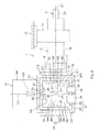
FIG. 2 is a side view of the electricpower steering system 1, showing the schematic configuration when theelectric motor 12 is fitted to the left side of thesteering column 15. TheECU 27 includes anECU box 28 and acontrol board 29. TheECU box 28 is securely fitted to thesecond housing 18. Thecontrol board 29 is accommodated in theECU box 28. Acontrol circuit 30 is mounted on thecontrol board 29. Thecontrol circuit 30 executes drive control over theelectric motor 12 on the basis of signals from thetorque sensor 19 and thevehicle speed sensor 26. - The
control board 29 has afirst end portion 31 and asecond end portion 32 that are a pair of end portions in a first direction X1 parallel to a central axis C1 of thesteering shaft 3. In addition, thecontrol board 29 has athird end portion 33 and afourth end portion 34 that are a pair of end portions in a second direction X2 perpendicular to the first direction X1. - A first terminal group G1 is provided at the
first end portion 31 that is one end portion in the first direction X1. The first terminal group G1 may function as a first connection portion group that is connectable to thetorque sensor 19. A second terminal group G2 is provided at thesecond end portion 32 that is the other end portion in the first direction X1. The second terminal group G2 may function as a second connection portion group that is connectable to thetorque sensor 19. - A third terminal group G3 is provided at the
third end portion 33 that is one end portion in the second direction X2. The third terminal group G3 may function as a third connection portion group that is connectable to theelectric motor 12. Apower input connector 35 and a vehiclesignal input connector 36 are arranged at thefourth end portion 34 that is the other end portion in the second direction X2. Thepower input connector 35 may function as a power input connection portion that receives power from an in-vehicle battery. The vehiclesignal input connector 36 may function as a vehicle signal input connection portion that receives a vehicle signal, such as a signal from thevehicle speed sensor 26. - The first terminal group G1 that may function as the first connection portion group is formed of
first terminals 371 to 374 that may function as a plurality of first connection portions. Thefirst terminals 371 to 374 are connectable tocorresponding output terminals 191 to 194 from thetorque sensor 19. The second terminal group G2 that may function as the second connection portion group is formed ofsecond terminals 381 to 384 that may function as a plurality of second connection portions. Thesecond terminals 381 to 384 are connectable to thecorresponding output terminals 191 to 194 from thetorque sensor 19. For example, thefirst terminals 371 to 374 and thesecond terminals 381 to 384 are formed of through-holes, and theoutput terminals 191 to 194 from thetorque sensor 19 are formed of pin terminals that are passed through the through-holes and soldered. - When the
control board 29 is viewed from a direction perpendicular to the surface of the control board 29 (direction perpendicular to the sheet on whichFIG. 2 is drawn), thefirst terminals 371 to 374 that constitute the first terminal group G1 and thesecond terminals 381 to 384 that constitute the second terminal group G2 are arranged so as to be symmetric with respect to an intersection point P1 of the central axis C1 of thesteering shaft 3 and the central axis C2 of theoutput shaft 12b of theelectric motor 12. - The third terminal group G3 that may function as the third connection portion group is formed such that
third terminals 40 that serve as a plurality of third connection portions that are respectively connected to a plurality of power supply bus bar terminals 39 (corresponding to U, V and W phases, for example) from theelectric motor 12 are arranged on aterminal base 50. When theelectric motor 12 is a brushless motor, the third terminal group G3 may include a rotation angle signal input terminal (not shown) that receives a rotation angle signal from theelectric motor 12. - As shown in
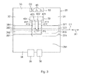
FIG. 3 , thefirst terminal 371 and thesecond terminal 381 that are arranged so as to be symmetric with respect to the intersection point P1 are both connected to afirst input portion 421 of thecontrol circuit 30 via aline 411 provided on thecontrol board 29. Thefirst terminal 372 and thesecond terminal 382 that are arranged so as to be symmetric with respect to the intersection point P1 are both connected to asecond input portion 422 of thecontrol circuit 30 via aline 412 provided on thecontrol board 29. - In addition, the
first terminal 373 and thesecond terminal 383 that are arranged so as to be symmetric with respect to the intersection point P1 are both connected to athird input portion 423 via aline 413. Thefirst terminal 374 and thesecond terminal 384 that are arranged so as to be symmetric with respect to the intersection point P1 are both connected to afourth input portion 424 via aline 414. -
FIG. 4 is a side view of the electricpower steering system 1, showing the schematic configuration when theelectric motor 12 is fitted to the right side of thesteering column 15. - In the case shown in
FIG. 2 in which theelectric motor 12 is fitted to the left side of thesteering column 15, the first terminal group G1 that may function as the first connection portion group is arranged on thetorque sensor 19 side and is connected to thetorque sensor 19; whereas, in the case shown inFIG. 4 in which theelectric motor 12 is fitted to the right side of thesteering column 15, the second terminal group G2 that may function as the second connection portion group is arranged on thetorque sensor 19 side and is connected to thetorque sensor 19. In both the case inFIG. 2 and the case inFIG. 4 , thesame control board 29 is used. The other configuration is the same as that inFIG. 2 . - According to the present embodiment, the orientation of the
control board 29 in the case where theelectric motor 12 is arranged on the left side of the central axis C1 of thesteering shaft 3 is different by 180° from the orientation of thecontrol board 29 in the case where theelectric motor 12 is arranged on the right side of the central axis C1 of thesteering shaft 3. In both of the cases, the third terminal group G3 faces theelectric motor 12. Thecontrol board 29 arranged in this way is connected to theECU box 28 fixed to thesecond housing 18 of thesteering column 15. - Even if the orientation of the
control board 29 is changed, one of the first terminal group G1 and the second terminal group G2 faces thetorque sensor 19. Therefore, the one of the terminal groups G1 and G2 is connected to thetorque sensor 19. In this way, irrespective of a change in the mounting position of theelectric motor 12, it is possible to use thesame control board 29. The number of third terminal group G3 (terminal base 50), to which theelectric motor 12 is connected and which tends to be large in size, is one. In addition, the two connection portion groups (the first terminal group G1 and the second terminal group G2), to which thetorque sensor 19 is connected and which are less likely to be increased in size, are provided. As a result, it is possible to reduce the size of thecontrol board 29. - In addition, irrespective of a change in the mounting position of the
electric motor 12, thepower input connector 35 and the vehiclesignal input connector 36 are arranged on the opposite side of thecontrol board 19 from theelectric motor 12. Therefore, it is possible to achieve a layout with high space efficiency. - In addition, when the
control board 29 is viewed from the direction perpendicular to the surface of thecontrol board 29 as shown inFIG. 2 , thefirst terminals 371 to 374 that constitute the first terminal group G1 and thesecond terminals 381 to 384 that constitute the second terminal group G2 are arranged so as to be symmetric with respect to the intersection point P1 of the central axis C1 of thesteering shaft 3 and the central axis C2 of theoutput shaft 12b of theelectric motor 12. With this configuration, one of the first terminal group G1 and the second terminal group G2, which faces thetorque sensor 19 when the orientation of thecontrol board 29 is changed in response to a change in the mounting position of theelectric motor 12, is connected to thetorque sensor 19. That is, irrespective of a change in the mounting position of theelectric motor 12, it is possible to use thesame control board 29. - In addition, the
first terminals 371 to 374 and the correspondingsecond terminals 381 to 384 are connected to thecorresponding input portions 421 to 424 of thecontrol circuit 30 via the correspondinglines 411 to 414 provided on thecontrol board 29. Therefore, regardless of whether thetorque sensor 19 is connected to the first terminal group G1 or to the second terminal group G2, it is possible to transmit signals from the connected terminal group to thecontrol circuit 30. -
FIG. 5 shows acontrol board 29A according to another embodiment of the invention. The present embodiment differs from the embodiment shown inFIG. 3 in the following point. Thetorque sensor 19 is formed of, for example, a Hall IC, and a pair ofoutput terminals torque sensor 19 is configured to output signals having the same absolute value and opposite in sign to each other. Similarly, a pair ofoutput terminals - The
first terminal 371 that is connectable to theoutput terminal 191 in the state inFIG. 2 and thesecond terminal 382 that is connectable to theoutput terminal 192 in the state inFIG. 4 are both connected to thefirst input portion 421 of thecontrol circuit 30 via aline 431 provided on thecontrol board 29A. - In addition, the
first terminal 372 that is connectable to theoutput terminal 192 in the state inFIG. 2 and thesecond terminal 381 that is connectable to theoutput terminal 191 in the state inFig. 4 are both connected to thesecond input portion 422 of thecontrol circuit 30 via aline 432 provided on thecontrol board 29A. - The
first terminal 373 that is connectable to theoutput terminal 193 in the state inFIG. 2 and thesecond terminal 384 that is connectable to theoutput terminal 194 in the state inFIG. 4 are both connected to thethird input portion 423 of thecontrol circuit 30 via aline 433 provided on thecontrol board 29A. - In addition, the
first terminal 374 that is connectable to theoutput terminal 194 in the state inFIG. 2 and thesecond terminal 383 that is connectable to theoutput terminal 193 in the state inFIG. 4 are both connected to thefourth input portion 424 of thecontrol circuit 30 via aline 434 provided on thecontrol board 29A. - According to the present embodiment, when the
torque sensor 19 is connected to the first terminal group G1, thefirst terminal 371 and thefirst terminal 372 are respectively connected to thefirst input portion 421 and thesecond input portion 422; whereas, when thetorque sensor 19 is connected to the second terminal group G2, thesecond terminal 381 and thesecond terminal 382 are respectively connected to thesecond input portion 422 and thefirst input portion 421. - In addition, when the
torque sensor 19 is connected to the first terminal group G1, thefirst terminal 373 and thefirst terminal 374 are respectively connected to thethird input portion 423 and thefourth input portion 424; whereas, when thetorque sensor 19 is connected to the second terminal group G2, thesecond terminal 383 and thesecond terminal 384 are respectively connected to thefourth input portion 424 and thethird input portion 423. - In this way, between the case where the
torque sensor 19 is connected to the first terminal group G1 and the case where thetorque sensor 19 is connected to the second terminal group G2, for example, the input portion of thecontrol circuit 30, which is connected to a corresponding one of thefirst terminal 371 and thesecond terminal 381 that are arranged so as to be symmetric with respect to an intersection point P1, is switched between thefirst input portion 421 and thesecond input portion 422, and the input portion of thecontrol circuit 30, which is connected to a corresponding one of thefirst terminal 372 and thesecond terminal 382 that are arranged so as to be symmetric to each other, is switched between thesecond input portion 422 and thefirst input portion 421. Thus, the signs of signals that are input from thetorque sensor 19 to thecontrol circuit 30 are inverted, so it is possible to generate steering assist force by rotating theelectric motor 12 in opposite directions. Thus, irrespective of a change in the mounting position of theelectric motor 12, it is possible to commonalize a program configuration of thecontrol circuit 30. - The invention is not limited to the above embodiments. For example, a brushless motor may be used as the
electric motor 12. In addition, in the above embodiments, the number of the first terminals that may function as the first connection portions is four, the number of the second terminals that may function as the second connection portions is four, and the number of the third terminals that may function as the third connection portions is three; however, the invention is not limited to this configuration. The numbers of the terminals that may function as the respective connection portions may be variously changed on the basis of an electric motor used, or the like. Other than the above, various modifications may be carried out within the scope of the appended claims of the invention.
Claims (5)
- An electric power steering system, characterized by comprising:an outer frame by which a steering transmission shaft is rotatably supported;a torque sensor that is supported by the outer frame, and that detects a steering torque;an electric motor that is supported by the outer frame, and that transmits power to the steering transmission shaft via a transmission mechanism; anda control board that is fitted to the outer frame, and on which a control circuit that controls driving of the electric motor based on a signal from the torque sensor is mounted, whereinthe control board has a first connection portion group and a second connection portion group that are respectively arranged at a pair of end portions in a first direction that is parallel to a central axis of the steering transmission shaft and that are selectively connectable to the torque sensor, and has a third connection portion group that is arranged at one end portion in a second direction that is perpendicular to the first direction and that is connectable to the electric motor.
- The electric power steering system according to claim 1, wherein a power input connection portion and a vehicle signal input connection portion are arranged at the other end portion of the control board in the second direction.
- The electric power steering system according to claim 1 or 2, wherein, when the control board is viewed from a direction perpendicular to a plate face of the control board, a plurality of first connection portions that constitute the first connection portion group and a plurality of second connection portions that constitute the second connection portion group are arranged so as to be symmetric with respect to an intersection point of the central axis of the steering transmission shaft and a central axis of an output shaft of the electric motor.
- The electric power steering system according to claim 3, wherein each of the first connection portions and a corresponding one of the second connection portions are connected to a common corresponding one of input portions of the control circuit via a corresponding one of lines provided on the control board.
- The electric power steering system according to claim 4, wherein:the torque sensor has at least one pair of output terminals that output signals having the same absolute value and opposite in sign to each other;the first connection portion that is connectable to one of the pair of output terminals and the second connection portion that is connectable to the other one of the pair of output terminals are connected to a common corresponding one of the input portions of the control circuit via a corresponding one of the lines provided on the control board; andthe first connection portion that is connectable to the other one of the pair of output terminals and the second connection portion that is connectable to the one of the pair of output terminals are connected to a common corresponding one of the input portions of the control circuit via a corresponding one of the lines provided on the control board.
Applications Claiming Priority (1)
| Application Number | Priority Date | Filing Date | Title |
|---|---|---|---|
| JP2011186976A JP2013049299A (en) | 2011-08-30 | 2011-08-30 | Electric power steering system |
Publications (3)
| Publication Number | Publication Date |
|---|---|
| EP2565105A2 true EP2565105A2 (en) | 2013-03-06 |
| EP2565105A3 EP2565105A3 (en) | 2013-07-17 |
| EP2565105B1 EP2565105B1 (en) | 2014-12-17 |
Family
ID=47143501
Family Applications (1)
| Application Number | Title | Priority Date | Filing Date |
|---|---|---|---|
| EP12178439.1A Not-in-force EP2565105B1 (en) | 2011-08-30 | 2012-07-30 | Electric power steering system |
Country Status (4)
| Country | Link |
|---|---|
| US (1) | US8550205B2 (en) |
| EP (1) | EP2565105B1 (en) |
| JP (1) | JP2013049299A (en) |
| CN (1) | CN103072620B (en) |
Families Citing this family (2)
| Publication number | Priority date | Publication date | Assignee | Title |
|---|---|---|---|---|
| US10308277B2 (en) * | 2015-07-22 | 2019-06-04 | Steering Solutions Ip Holding Corporation | Spherical washer assembly |
| US10288506B2 (en) * | 2016-10-19 | 2019-05-14 | Steering Solutions Ip Holding Corporation | Integrated torque sensor in controller board and EPS system incorporating the same |
Citations (1)
| Publication number | Priority date | Publication date | Assignee | Title |
|---|---|---|---|---|
| JP2004130890A (en) | 2002-10-09 | 2004-04-30 | Denso Corp | Electric power steering device |
Family Cites Families (5)
| Publication number | Priority date | Publication date | Assignee | Title |
|---|---|---|---|---|
| JP3774624B2 (en) * | 2000-10-18 | 2006-05-17 | 三菱電機株式会社 | Electric power steering device |
| JP4158602B2 (en) * | 2003-05-28 | 2008-10-01 | トヨタ自動車株式会社 | Method for mounting electric power steering device on vehicle |
| JP4661508B2 (en) * | 2005-09-30 | 2011-03-30 | 日本精工株式会社 | Electric power steering device |
| KR100646404B1 (en) * | 2005-10-26 | 2006-11-14 | 주식회사 만도 | Electronic control device and electric power assist steering device of automobile |
| WO2007119757A1 (en) | 2006-04-11 | 2007-10-25 | Nsk Ltd. | Electric power steering device and method of assembling the same |
-
2011
- 2011-08-30 JP JP2011186976A patent/JP2013049299A/en not_active Withdrawn
-
2012
- 2012-07-23 US US13/555,509 patent/US8550205B2/en not_active Expired - Fee Related
- 2012-07-30 EP EP12178439.1A patent/EP2565105B1/en not_active Not-in-force
- 2012-08-22 CN CN201210301709.6A patent/CN103072620B/en not_active Expired - Fee Related
Patent Citations (1)
| Publication number | Priority date | Publication date | Assignee | Title |
|---|---|---|---|---|
| JP2004130890A (en) | 2002-10-09 | 2004-04-30 | Denso Corp | Electric power steering device |
Also Published As
| Publication number | Publication date |
|---|---|
| US8550205B2 (en) | 2013-10-08 |
| US20130048412A1 (en) | 2013-02-28 |
| CN103072620B (en) | 2016-07-13 |
| EP2565105B1 (en) | 2014-12-17 |
| CN103072620A (en) | 2013-05-01 |
| JP2013049299A (en) | 2013-03-14 |
| EP2565105A3 (en) | 2013-07-17 |
Similar Documents
| Publication | Publication Date | Title |
|---|---|---|
| EP2604489B1 (en) | Vehicle steering system | |
| EP3279060A1 (en) | Vehicle steering system | |
| JP6435080B1 (en) | Steering device | |
| CN111114625A (en) | Steering control device | |
| JP5311102B2 (en) | Vehicle steering system | |
| JP5017423B2 (en) | Steering control device | |
| EP2565105B1 (en) | Electric power steering system | |
| CN117022426A (en) | Electric motors and steer-by-wire devices having such electric motors | |
| EP1769999A1 (en) | Electric power steering device and attachment structure for motor and controller for the same | |
| KR20160111065A (en) | Electric Power Steering Apparatus | |
| US20110313620A1 (en) | Steering control apparatus | |
| KR20150025377A (en) | Rear steering apparatus, and position sensor module applied to the same | |
| US12172707B2 (en) | Power steering system for vehicle | |
| US20230052990A1 (en) | Electric power steering apparatus | |
| US12604393B2 (en) | Electronic control device and ground line routing method | |
| US20060063441A1 (en) | Steering apparatus for ship propeller | |
| JP7472745B2 (en) | Motor Drive System | |
| KR20240178421A (en) | Steer-by-wire type steering apparatus | |
| US20160031476A1 (en) | Electric power steering device | |
| CN114516363A (en) | Steering apparatus and method | |
| JP2009029287A (en) | Electric power steering device | |
| CN113771937A (en) | Electric power steering assist method, system and assist device thereof | |
| JP3991643B2 (en) | Vehicle steering system | |
| US12431771B2 (en) | Power pack flexible electrical connector location | |
| KR20120139968A (en) | Torque sensor system and electric power steering apparatus having the same |
Legal Events
| Date | Code | Title | Description |
|---|---|---|---|
| PUAI | Public reference made under article 153(3) epc to a published international application that has entered the european phase |
Free format text: ORIGINAL CODE: 0009012 |
|
| AK | Designated contracting states |
Kind code of ref document: A2 Designated state(s): AL AT BE BG CH CY CZ DE DK EE ES FI FR GB GR HR HU IE IS IT LI LT LU LV MC MK MT NL NO PL PT RO RS SE SI SK SM TR |
|
| AX | Request for extension of the european patent |
Extension state: BA ME |
|
| PUAL | Search report despatched |
Free format text: ORIGINAL CODE: 0009013 |
|
| AK | Designated contracting states |
Kind code of ref document: A3 Designated state(s): AL AT BE BG CH CY CZ DE DK EE ES FI FR GB GR HR HU IE IS IT LI LT LU LV MC MK MT NL NO PL PT RO RS SE SI SK SM TR |
|
| AX | Request for extension of the european patent |
Extension state: BA ME |
|
| RIC1 | Information provided on ipc code assigned before grant |
Ipc: B62D 5/04 20060101AFI20130612BHEP |
|
| 17P | Request for examination filed |
Effective date: 20140115 |
|
| RBV | Designated contracting states (corrected) |
Designated state(s): AL AT BE BG CH CY CZ DE DK EE ES FI FR GB GR HR HU IE IS IT LI LT LU LV MC MK MT NL NO PL PT RO RS SE SI SK SM TR |
|
| GRAP | Despatch of communication of intention to grant a patent |
Free format text: ORIGINAL CODE: EPIDOSNIGR1 |
|
| INTG | Intention to grant announced |
Effective date: 20140627 |
|
| GRAS | Grant fee paid |
Free format text: ORIGINAL CODE: EPIDOSNIGR3 |
|
| GRAA | (expected) grant |
Free format text: ORIGINAL CODE: 0009210 |
|
| AK | Designated contracting states |
Kind code of ref document: B1 Designated state(s): AL AT BE BG CH CY CZ DE DK EE ES FI FR GB GR HR HU IE IS IT LI LT LU LV MC MK MT NL NO PL PT RO RS SE SI SK SM TR |
|
| REG | Reference to a national code |
Ref country code: GB Ref legal event code: FG4D |
|
| REG | Reference to a national code |
Ref country code: CH Ref legal event code: EP |
|
| REG | Reference to a national code |
Ref country code: IE Ref legal event code: FG4D |
|
| REG | Reference to a national code |
Ref country code: AT Ref legal event code: REF Ref document number: 701664 Country of ref document: AT Kind code of ref document: T Effective date: 20150115 |
|
| REG | Reference to a national code |
Ref country code: DE Ref legal event code: R096 Ref document number: 602012004321 Country of ref document: DE Effective date: 20150212 |
|
| PG25 | Lapsed in a contracting state [announced via postgrant information from national office to epo] |
Ref country code: NO Free format text: LAPSE BECAUSE OF FAILURE TO SUBMIT A TRANSLATION OF THE DESCRIPTION OR TO PAY THE FEE WITHIN THE PRESCRIBED TIME-LIMIT Effective date: 20150317 Ref country code: LT Free format text: LAPSE BECAUSE OF FAILURE TO SUBMIT A TRANSLATION OF THE DESCRIPTION OR TO PAY THE FEE WITHIN THE PRESCRIBED TIME-LIMIT Effective date: 20141217 Ref country code: FI Free format text: LAPSE BECAUSE OF FAILURE TO SUBMIT A TRANSLATION OF THE DESCRIPTION OR TO PAY THE FEE WITHIN THE PRESCRIBED TIME-LIMIT Effective date: 20141217 |
|
| REG | Reference to a national code |
Ref country code: LT Ref legal event code: MG4D |
|
| PG25 | Lapsed in a contracting state [announced via postgrant information from national office to epo] |
Ref country code: SE Free format text: LAPSE BECAUSE OF FAILURE TO SUBMIT A TRANSLATION OF THE DESCRIPTION OR TO PAY THE FEE WITHIN THE PRESCRIBED TIME-LIMIT Effective date: 20141217 Ref country code: LV Free format text: LAPSE BECAUSE OF FAILURE TO SUBMIT A TRANSLATION OF THE DESCRIPTION OR TO PAY THE FEE WITHIN THE PRESCRIBED TIME-LIMIT Effective date: 20141217 Ref country code: HR Free format text: LAPSE BECAUSE OF FAILURE TO SUBMIT A TRANSLATION OF THE DESCRIPTION OR TO PAY THE FEE WITHIN THE PRESCRIBED TIME-LIMIT Effective date: 20141217 Ref country code: GR Free format text: LAPSE BECAUSE OF FAILURE TO SUBMIT A TRANSLATION OF THE DESCRIPTION OR TO PAY THE FEE WITHIN THE PRESCRIBED TIME-LIMIT Effective date: 20150318 Ref country code: RS Free format text: LAPSE BECAUSE OF FAILURE TO SUBMIT A TRANSLATION OF THE DESCRIPTION OR TO PAY THE FEE WITHIN THE PRESCRIBED TIME-LIMIT Effective date: 20141217 |
|
| REG | Reference to a national code |
Ref country code: AT Ref legal event code: MK05 Ref document number: 701664 Country of ref document: AT Kind code of ref document: T Effective date: 20141217 |
|
| PG25 | Lapsed in a contracting state [announced via postgrant information from national office to epo] |
Ref country code: NL Free format text: LAPSE BECAUSE OF FAILURE TO SUBMIT A TRANSLATION OF THE DESCRIPTION OR TO PAY THE FEE WITHIN THE PRESCRIBED TIME-LIMIT Effective date: 20141217 |
|
| PG25 | Lapsed in a contracting state [announced via postgrant information from national office to epo] |
Ref country code: EE Free format text: LAPSE BECAUSE OF FAILURE TO SUBMIT A TRANSLATION OF THE DESCRIPTION OR TO PAY THE FEE WITHIN THE PRESCRIBED TIME-LIMIT Effective date: 20141217 Ref country code: RO Free format text: LAPSE BECAUSE OF FAILURE TO SUBMIT A TRANSLATION OF THE DESCRIPTION OR TO PAY THE FEE WITHIN THE PRESCRIBED TIME-LIMIT Effective date: 20141217 Ref country code: CZ Free format text: LAPSE BECAUSE OF FAILURE TO SUBMIT A TRANSLATION OF THE DESCRIPTION OR TO PAY THE FEE WITHIN THE PRESCRIBED TIME-LIMIT Effective date: 20141217 Ref country code: SK Free format text: LAPSE BECAUSE OF FAILURE TO SUBMIT A TRANSLATION OF THE DESCRIPTION OR TO PAY THE FEE WITHIN THE PRESCRIBED TIME-LIMIT Effective date: 20141217 Ref country code: ES Free format text: LAPSE BECAUSE OF FAILURE TO SUBMIT A TRANSLATION OF THE DESCRIPTION OR TO PAY THE FEE WITHIN THE PRESCRIBED TIME-LIMIT Effective date: 20141217 |
|
| PG25 | Lapsed in a contracting state [announced via postgrant information from national office to epo] |
Ref country code: AT Free format text: LAPSE BECAUSE OF FAILURE TO SUBMIT A TRANSLATION OF THE DESCRIPTION OR TO PAY THE FEE WITHIN THE PRESCRIBED TIME-LIMIT Effective date: 20141217 Ref country code: PL Free format text: LAPSE BECAUSE OF FAILURE TO SUBMIT A TRANSLATION OF THE DESCRIPTION OR TO PAY THE FEE WITHIN THE PRESCRIBED TIME-LIMIT Effective date: 20141217 Ref country code: IS Free format text: LAPSE BECAUSE OF FAILURE TO SUBMIT A TRANSLATION OF THE DESCRIPTION OR TO PAY THE FEE WITHIN THE PRESCRIBED TIME-LIMIT Effective date: 20150417 |
|
| REG | Reference to a national code |
Ref country code: DE Ref legal event code: R097 Ref document number: 602012004321 Country of ref document: DE |
|
| PLBE | No opposition filed within time limit |
Free format text: ORIGINAL CODE: 0009261 |
|
| STAA | Information on the status of an ep patent application or granted ep patent |
Free format text: STATUS: NO OPPOSITION FILED WITHIN TIME LIMIT |
|
| PG25 | Lapsed in a contracting state [announced via postgrant information from national office to epo] |
Ref country code: DK Free format text: LAPSE BECAUSE OF FAILURE TO SUBMIT A TRANSLATION OF THE DESCRIPTION OR TO PAY THE FEE WITHIN THE PRESCRIBED TIME-LIMIT Effective date: 20141217 |
|
| 26N | No opposition filed |
Effective date: 20150918 |
|
| PG25 | Lapsed in a contracting state [announced via postgrant information from national office to epo] |
Ref country code: IT Free format text: LAPSE BECAUSE OF FAILURE TO SUBMIT A TRANSLATION OF THE DESCRIPTION OR TO PAY THE FEE WITHIN THE PRESCRIBED TIME-LIMIT Effective date: 20141217 |
|
| PG25 | Lapsed in a contracting state [announced via postgrant information from national office to epo] |
Ref country code: MC Free format text: LAPSE BECAUSE OF FAILURE TO SUBMIT A TRANSLATION OF THE DESCRIPTION OR TO PAY THE FEE WITHIN THE PRESCRIBED TIME-LIMIT Effective date: 20141217 Ref country code: SI Free format text: LAPSE BECAUSE OF FAILURE TO SUBMIT A TRANSLATION OF THE DESCRIPTION OR TO PAY THE FEE WITHIN THE PRESCRIBED TIME-LIMIT Effective date: 20141217 |
|
| REG | Reference to a national code |
Ref country code: CH Ref legal event code: PL |
|
| PG25 | Lapsed in a contracting state [announced via postgrant information from national office to epo] |
Ref country code: LU Free format text: LAPSE BECAUSE OF FAILURE TO SUBMIT A TRANSLATION OF THE DESCRIPTION OR TO PAY THE FEE WITHIN THE PRESCRIBED TIME-LIMIT Effective date: 20150730 |
|
| REG | Reference to a national code |
Ref country code: IE Ref legal event code: MM4A |
|
| PG25 | Lapsed in a contracting state [announced via postgrant information from national office to epo] |
Ref country code: LI Free format text: LAPSE BECAUSE OF NON-PAYMENT OF DUE FEES Effective date: 20150731 Ref country code: CH Free format text: LAPSE BECAUSE OF NON-PAYMENT OF DUE FEES Effective date: 20150731 |
|
| PG25 | Lapsed in a contracting state [announced via postgrant information from national office to epo] |
Ref country code: BE Free format text: LAPSE BECAUSE OF FAILURE TO SUBMIT A TRANSLATION OF THE DESCRIPTION OR TO PAY THE FEE WITHIN THE PRESCRIBED TIME-LIMIT Effective date: 20141217 |
|
| REG | Reference to a national code |
Ref country code: FR Ref legal event code: PLFP Year of fee payment: 5 |
|
| PG25 | Lapsed in a contracting state [announced via postgrant information from national office to epo] |
Ref country code: IE Free format text: LAPSE BECAUSE OF NON-PAYMENT OF DUE FEES Effective date: 20150730 |
|
| GBPC | Gb: european patent ceased through non-payment of renewal fee |
Effective date: 20160730 |
|
| PG25 | Lapsed in a contracting state [announced via postgrant information from national office to epo] |
Ref country code: MT Free format text: LAPSE BECAUSE OF FAILURE TO SUBMIT A TRANSLATION OF THE DESCRIPTION OR TO PAY THE FEE WITHIN THE PRESCRIBED TIME-LIMIT Effective date: 20141217 |
|
| PG25 | Lapsed in a contracting state [announced via postgrant information from national office to epo] |
Ref country code: HU Free format text: LAPSE BECAUSE OF FAILURE TO SUBMIT A TRANSLATION OF THE DESCRIPTION OR TO PAY THE FEE WITHIN THE PRESCRIBED TIME-LIMIT; INVALID AB INITIO Effective date: 20120730 Ref country code: GB Free format text: LAPSE BECAUSE OF NON-PAYMENT OF DUE FEES Effective date: 20160730 Ref country code: BG Free format text: LAPSE BECAUSE OF FAILURE TO SUBMIT A TRANSLATION OF THE DESCRIPTION OR TO PAY THE FEE WITHIN THE PRESCRIBED TIME-LIMIT Effective date: 20141217 Ref country code: SM Free format text: LAPSE BECAUSE OF FAILURE TO SUBMIT A TRANSLATION OF THE DESCRIPTION OR TO PAY THE FEE WITHIN THE PRESCRIBED TIME-LIMIT Effective date: 20141217 |
|
| REG | Reference to a national code |
Ref country code: FR Ref legal event code: PLFP Year of fee payment: 6 |
|
| PG25 | Lapsed in a contracting state [announced via postgrant information from national office to epo] |
Ref country code: CY Free format text: LAPSE BECAUSE OF FAILURE TO SUBMIT A TRANSLATION OF THE DESCRIPTION OR TO PAY THE FEE WITHIN THE PRESCRIBED TIME-LIMIT Effective date: 20141217 |
|
| PG25 | Lapsed in a contracting state [announced via postgrant information from national office to epo] |
Ref country code: TR Free format text: LAPSE BECAUSE OF FAILURE TO SUBMIT A TRANSLATION OF THE DESCRIPTION OR TO PAY THE FEE WITHIN THE PRESCRIBED TIME-LIMIT Effective date: 20141217 |
|
| REG | Reference to a national code |
Ref country code: FR Ref legal event code: PLFP Year of fee payment: 7 |
|
| PG25 | Lapsed in a contracting state [announced via postgrant information from national office to epo] |
Ref country code: MK Free format text: LAPSE BECAUSE OF FAILURE TO SUBMIT A TRANSLATION OF THE DESCRIPTION OR TO PAY THE FEE WITHIN THE PRESCRIBED TIME-LIMIT Effective date: 20141217 |
|
| PG25 | Lapsed in a contracting state [announced via postgrant information from national office to epo] |
Ref country code: PT Free format text: LAPSE BECAUSE OF FAILURE TO SUBMIT A TRANSLATION OF THE DESCRIPTION OR TO PAY THE FEE WITHIN THE PRESCRIBED TIME-LIMIT Effective date: 20141217 |
|
| PG25 | Lapsed in a contracting state [announced via postgrant information from national office to epo] |
Ref country code: AL Free format text: LAPSE BECAUSE OF FAILURE TO SUBMIT A TRANSLATION OF THE DESCRIPTION OR TO PAY THE FEE WITHIN THE PRESCRIBED TIME-LIMIT Effective date: 20141217 |
|
| PGFP | Annual fee paid to national office [announced via postgrant information from national office to epo] |
Ref country code: FR Payment date: 20230620 Year of fee payment: 12 |
|
| PGFP | Annual fee paid to national office [announced via postgrant information from national office to epo] |
Ref country code: DE Payment date: 20230607 Year of fee payment: 12 |
|
| REG | Reference to a national code |
Ref country code: DE Ref legal event code: R119 Ref document number: 602012004321 Country of ref document: DE |
|
| PG25 | Lapsed in a contracting state [announced via postgrant information from national office to epo] |
Ref country code: DE Free format text: LAPSE BECAUSE OF NON-PAYMENT OF DUE FEES Effective date: 20250201 |
|
| PG25 | Lapsed in a contracting state [announced via postgrant information from national office to epo] |
Ref country code: FR Free format text: LAPSE BECAUSE OF NON-PAYMENT OF DUE FEES Effective date: 20240731 |