EP2565111B1 - Fahrzeugschwinge - Google Patents
Fahrzeugschwinge Download PDFInfo
- Publication number
- EP2565111B1 EP2565111B1 EP12179559.5A EP12179559A EP2565111B1 EP 2565111 B1 EP2565111 B1 EP 2565111B1 EP 12179559 A EP12179559 A EP 12179559A EP 2565111 B1 EP2565111 B1 EP 2565111B1
- Authority
- EP
- European Patent Office
- Prior art keywords
- portions
- pair
- support
- arm portions
- arm
- Prior art date
- Legal status (The legal status is an assumption and is not a legal conclusion. Google has not performed a legal analysis and makes no representation as to the accuracy of the status listed.)
- Not-in-force
Links
Images



Classifications
-
- B—PERFORMING OPERATIONS; TRANSPORTING
- B62—LAND VEHICLES FOR TRAVELLING OTHERWISE THAN ON RAILS
- B62K—CYCLES; CYCLE FRAMES; CYCLE STEERING DEVICES; RIDER-OPERATED TERMINAL CONTROLS SPECIALLY ADAPTED FOR CYCLES; CYCLE AXLE SUSPENSIONS; CYCLE SIDECARS, FORECARS, OR THE LIKE
- B62K25/00—Axle suspensions
- B62K25/04—Axle suspensions for mounting axles resiliently on cycle frame or fork
- B62K25/28—Axle suspensions for mounting axles resiliently on cycle frame or fork with pivoted chain-stay
- B62K25/286—Axle suspensions for mounting axles resiliently on cycle frame or fork with pivoted chain-stay the shock absorber being connected to the chain-stay via a linkage mechanism
-
- B—PERFORMING OPERATIONS; TRANSPORTING
- B62—LAND VEHICLES FOR TRAVELLING OTHERWISE THAN ON RAILS
- B62K—CYCLES; CYCLE FRAMES; CYCLE STEERING DEVICES; RIDER-OPERATED TERMINAL CONTROLS SPECIALLY ADAPTED FOR CYCLES; CYCLE AXLE SUSPENSIONS; CYCLE SIDECARS, FORECARS, OR THE LIKE
- B62K25/00—Axle suspensions
- B62K25/04—Axle suspensions for mounting axles resiliently on cycle frame or fork
- B62K25/28—Axle suspensions for mounting axles resiliently on cycle frame or fork with pivoted chain-stay
- B62K25/283—Axle suspensions for mounting axles resiliently on cycle frame or fork with pivoted chain-stay for cycles without a pedal crank, e.g. motorcycles
Definitions
- the present invention relates to a swing arm for a vehicle, and in particular to the type of swing arm formed from a pair of left and right arm portions which extend in the longitudinal direction, a pivot portion which is formed on the front ends of the arm portions, an axle support portion which is formed on the rear ends of the arm portions so as to pivotally support an axle of a rear wheel, and a cross portion which is arranged between the arm portions and connects the arm portions behind the pivot portion, which are integrally formed with each other by moulding.
- At least the cross portion is formed into a hollow shape, and a pair of left and right support bosses for supporting a shock absorber are integrally formed on a lower wall or an upper wall of the cross portion in an outwardly projecting manner.
- a swing arm using a light alloy such as an aluminium alloy or a magnesium alloy, for enhancing the reduction of weight and the attraction of a product.
- a swing arm is integrally formed by die-casting using an aluminium alloy.
- the present invention has been made in view of the above-mentioned circumstances, and it is an object of at least the preferred embodiments of the present invention to provide a swing arm for a vehicle where the rigidity of a support boss formed on a cross portion for supporting a shock absorber can be increased while suppressing the occurrence of cavities.
- a swing arm accoridng to the preamble of claim 1 is disclosed in JP 2011- 093410 .
- a similar swing arm is disclosed in EP 0295799 .
- a swing arm for a vehicle where a pair of left and right arm portions which extend in the longitudinal direction, a pivot portion which is formed on front ends of the arm portions, an axle support portion which is formed on rear ends of the arm portions so as to pivotally support an axle of a rear wheel, and a cross portion which is arranged between the arm portions and connects the arm portions behind the pivot portion are integrally formed with each other by moulding, at least the cross portion is formed into a hollow shape, and a pair of left and right support bosses for supporting a shock absorber is integrally formed on a lower wall or an upper wall of the cross portion in an outwardly projecting manner, wherein the pivot portion is contiguously formed with the arm portions in the lateral direction of the vehicle so as to connect front ends of the arm portions to each other; and an opening portion whose peripheral portion is endlessly contiguously formed and whose upper and lower ends are open is formed by the cross portion, the pivot portion and the pair of left and right arm portions;
- the opening portion is formed by the pivot portion which is contiguously formed to connect both arm portions, the cross portion and the pair of left and right arm portions, such that the opening portion has its upper and lower ends open. Accordingly, the rigidity of the front portion of the swing arm can be increased. Further, out of the lower wall and the upper wall of the cross portion, on the inner surface of the wall on which the support bosses are formed, , the pair of left and right recessed portions are formed and also the pair of left and right reinforcing ribs are integrally formed. Accordingly, it is possible to efficiently increase the rigidity of the cross portion while avoiding an increase of wall thickness of the cross portion at the portions on which the support bosses are formed, and thereby the occurrence of cavity can be suppressed.
- a support hole is formed in the support boss behind a centre portion of the support boss in the longitudinal direction of the support boss, and the reinforcing ribs are formed so as to project forwardly from a rear wall of the cross portion, and front ends of the reinforcing ribs are positioned in front of rear ends of the recessed portions.
- the rigidity of the rear wall can be efficiently increased by the reinforcing ribs corresponding to the increase of a stress applied to the rear wall of the cross portion.
- the arm portions are formed into an angular cylindrical shape having a rectangular transverse cross section.
- the rigidity of the arm portion can be increased while reducing the number of parts.
- the shock absorber can be arranged to extend vertically and pass through the opening portion in a state where the shock absorber is supported by the support bosses which project toward the outside from the lower wall of the cross portion, and core removal holes through which a casting core can be removed are formed on inner walls of the both arm portions, at portions where the core removal holes face the opening portion.
- the core removal holes are formed at portions of the swing arm where the rigidity is increased due to the endless contiguous wall and hence, it is possible to avoid a large reduction in the rigidity of the swing arm due to the formation of the core removal holes.
- communication holes which allow the inside of the arm portions to communicate with the inside of the pivot portion are formed in connecting portions between the arm portions and the pivot portion respectively.
- a wall thickness of the swing arm which is formed by integral moulding can be made uniform, the occurrence of cavities can be also suppressed, and cores for forming the arm portions and a core for forming the pivot portion can be formed as an integral part.
- a pair of left and right bearings is interposed between the pivot portion and a support shaft (which is made to pass through the pivot portion in a state where the left and right bearings are arranged outside the pair of communication holes, and a pair of left and right first seal members which is arranged between the bearings and the communication holes and a pair of left and right second seal members which is arranged between the bearings and the outside are interposed between the pivot portion and the support shaft.
- a vehicle body frame F of a motorcycle includes: a head pipe 13 which supports a front fork 11 which pivotally supports a front wheel WF and a handlebar 12 in a steerable manner; a pair of left and right main frames 14 which extend in the rearward and downward direction from the head pipe 13; a down frame 15 which extends in the rearward and downward direction from the head pipe at a steeper angle than the main frames 14; a pair of left and right lower frames 16 which are connected to a lower end portion of the down frame 15 and extend in the rearward direction; a pair of left and right pivot frames 17 which have their upper end portions joined to rear end portions of the main frames 14, extend in the downward direction, and have their lower end portions connected to rear end portions of the lower frames 16; a pair of left and right seat rails 18 which have their front end portions connected to rear portions of the main frames 14 and extend in the rearward direction; a pair of left and right rear frames 19 which connect vertically intermediate portions of the pivot frames 17 with rear portions
- An engine E is mounted on the vehicle body frame F, and is arranged in a space surrounded by the main frames 14, the down frame 15, the lower frames 16, and the pivot frames.
- a front end portion of a swing arm 21 is pivotally supported in a vertically swingable manner by way of a support shaft 23, and the swing arm 21 pivotally supports an axle 22 of a rear wheel WR on a rear end portion thereof.
- a link mechanism 24 is arranged between the lower portions of the pivot frames 17 and the swing arm 21.
- the link mechanism 24 includes: a link rod 25 which has one end portion connected to the lower portions of the pivot frames 17 in a rotatable manner; and a link member 26 which is rotatably supported on the swing arm 21 and to which the other end portion of the link rod 25 is rotatably connected.
- a shock absorber 27 which includes a spring and a damper is arranged between the link member 26 and upper portions of the pivot frames 17.
- a transmission (not shown in the drawings) is housed inside a crankcase 28, which forms part of the engine.
- An output shaft 29 of the transmission projects from the crankcase 28.
- An endless chain 32 extends between and is wound around a drive sprocket 30 which is mounted on the output shaft 29 and a driven sprocket 31 which is mounted on the axle 22 of the rear wheel WR.
- a fuel tank 33 is mounted on the main frames 14 above the engine E, and a rider's seat 34 is arranged behind the fuel tank 33 and is supported on the seat rails 18.
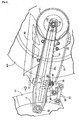
- the swing arm 21 is an integral body constituted of: a pair of left and right arm portions 35L, 35R which extend in the longitudinal direction; a pivot portion 36 formed at the front ends of the arm portions 35L, 35R; axle support portions 37 which are formed on the rear ends of the arm portions 35L, 35R so that the axle support portions 37 pivotally support the axle 22 of the rear wheel WR; and a cross portion 38 which connects the arm portions 35L, 35R to each other behind the pivot portion 36.
- the swing arm 21 is formed by integral moulding from a light alloy such as aluminium by gravity casting, for example.
- At least the cross portion 38 of the swing arm 21 is formed into a hollow shape.
- both arm portions 35L, 35R are formed into an angular cylindrical shape having a rectangular transverse cross section.
- the pivot portion 36 which connects the front ends of both arm portions 35L, 35R to each other and is contiguously formed with both arm portions 35L, 35R in the lateral direction of the vehicle is formed into a hollow circular cylindrical shape.
- communication holes 51, 51 which allow the insides of the arm portions 35L, 35R to communicate with the inside of the pivot portion 36 are formed in connecting portions between both arm portions 35L, 35R and the pivot portion 36.
- the pivot portion 36 When installed on the motorcycle, the pivot portion 36 is pivotally supported on the lower portions of the pair of left and right pivot frames 17 by way of the support shaft 23 which passes through the pivot portion 36.
- the support shaft 23 is constituted of a circular cylindrical collar 52 which passes through the pivot portion 36 over the whole length of the pivot portion 36, and a bolt 53 which passes through the pair of left and right pivot frames 17 and the collar 52.
- An enlarged diameter head portion 53a of the bolt 53 is engaged with and brought into contact with an outer side surface of the pivot frame 17 on one side, and a nut 54 is threadedly engaged with a portion of the bolt 53 projecting from the pivot frame 17 on the other side.
- Needle bearings 55, 55 which constitute a pair of left and right bearings, are interposed between the collar 52 of the support shaft 23 and the pivot portion 36, with the needle bearings 55, 55 being located laterally outside of the communication holes 51.
- Left and right first sealing members 56, 56 are interposed between the collar 52 of the support shaft 23 and the pivot portion 36, as well as between the needle bearings 55 and the communication holes 51.
- left and right second sealing members 57, 57 which are arranged between both needle bearings 55 and the outside, are interposed between the pivot portion 36 and the support shaft 23. That is, the pivot portion 36 includes, as integral parts thereof, small-diameter cylindrical portions 36a, 36a which have a narrowed outer diameter at both ends thereof, project outwardly, and are arranged coaxially with the pivot portion 36.
- the second sealing members 57 which are formed into a cap shape, are arranged in a sandwiched manner between the pivot frames 17 and end portions of the small-diameter cylindrical portions 36a, such that the second sealing members 57 close both end opening portions of the small-diameter cylindrical portions 36a and are resiliently brought into contact with outer peripheries of the small-diameter cylindrical portions 36a.
- left and right support bosses 39, 39 are integrally formed on the cross portion 38 and project downwardly from the lower wall 38a of the cross portion 38.
- a lower end portion of the shock absorber 27 is supported on the support bosses 39 by way of the link member 26 which constitutes a portion of the link mechanism 24.
- Support holes 40 through which a connection shaft 41 (see Fig. 2 ) for rotatably connecting the link member 26 to the support bosses 39 can pass are coaxially formed in the support bosses 39.
- the support holes 40 are arranged behind the centre portions of the support bosses 39 in the longitudinal direction. That is, the support holes 40 are formed in the support bosses 39 such that the centre axis of each support hole 40 is arranged behind a centre position C (at which a distance L from a front end of the support boss 39 to the centre portion C and a distance L from a rear end of the support boss 39 to the centre portion C are equal).
- a pair of left and right recessed portions 42, 42 which are indented toward a support boss 39 side is formed. Further, a pair of left and right reinforcing ribs 43, 43, each of which is positioned laterally outside one of the recessed portions 42, is integrally formed to project toward the inside of the cross portion 38. Further, the reinforcing ribs 43 are formed so that they extend forward from a rear wall 38c of the cross portion 38.
- the reinforcing ribs 43 are formed in a projecting manner integrally contiguous with an inner surface of the rear wall 38c of the cross portion 38, an inner surface of the lower wall 38a, and an inner surface of a rear half portion of the upper wall 38b of the cross portion 38, in such a manner that the front ends of the reinforcing ribs 43 are positioned in front of the rear ends of the recessed portions 42.
- an opening portion 44 whose peripheral portion is endlessly contiguously formed and whose upper and lower ends are open is formed by the cross portion 38, the pivot portion 36 and the pair of left and right arm portions 35L, 35R, and the shock absorber 27 can pass through the opening portion 44.
- core removing holes 45, 45 through which a sand core used in forming the swing arm 21 by moulding can be removed, are formed in inner walls of both arm portions 35L, 35R at portions so that the core removing holes 45, 45 face the opening portion 44.
- Caps 46, 46 are mounted on the respective core removing holes 45 after the formation of the swing arm 21 by moulding is completed.
- core removing holes 47, 47 through which a sand core can be removed are also formed in inner walls of rear portions of the pair of left and right arm portions 35L, 35R, and caps 48, 48 are mounted on the respective core removing holes 47.
- a chain case 49 is mounted on an upper wall of the rear portion of the left arm portion 35L of the swing arm 21, and a chain guide 50 is mounted on a lower wall of the rear portion of the arm portion 35L.
- the swing arm 21 is an integral body formed by moulding and is constituted of: the pair of left and right arm portions 35L, 35R which extends in the longitudinal direction; the pivot portion 36 which is formed between the front ends of the arm portions 35L, 35R; the axle support portions 37 which are mounted on the rear ends of the arm portions 35L, 35R such that the axle support portions 37 can pivotally support the axle 22 of the rear wheel WR; and the cross portion 38 which connects the arm portions 35L, 35R to each other behind the pivot portion 36; wherein at least the cross portion 38 is formed into a hollow shape, and the pair of left and right support bosses 39, 39 for supporting the shock absorber 27 is integrally formed with the cross portion 38 so as to project downwardly from the lower wall 38a of the cross portion 38.
- the pivot portion 36 is contiguously formed with both arm portions 35L, 35R in the lateral direction in a state where the pivot portion 36 connects the front ends of both arm portions 35L, 35R to each other, and the opening portion 44 whose peripheral portion is endlessly contiguously formed and whose upper and lower ends are open is formed by the cross portion 38, the pivot portion 36 and the pair of left and right arm portions 35L, 35R and hence, the rigidity of the front portion of the swing arm 21 can be increased.
- the left and right recessed portions 42, 42 which are indented toward the support bosses 39 side is formed on the inner surface of the lower wall 38a of the cross portion 38, and the left and right reinforcing ribs 43, 43 which are positioned laterally outside the respective recessed portions 42 are integrally formed on the inner surface of the lower wall 38a so as to project toward the inside of the cross portion 38. Accordingly, the rigidity of the cross portion 38 can be efficiently increased while avoiding an increase in wall thickness of the cross portion 38 at portions where the support bosses 39 are formed and thereby the occurrence of cavities can be suppressed.
- the support holes 40 are formed in the support bosses and are arranged behind the centre portion of the support bosses 39 in the longitudinal direction, the reinforcing ribs 43 are formed so as to extend forwardly from the rear wall 38c of the cross portion 38, and the front ends of the reinforcing ribs 43 are arranged in front of the rear ends of the recessed portions 42. Accordingly, the rigidity of the rear wall 38c can be efficiently increased by the reinforcing ribs 43 corresponding to the increase of a stress applied to the rear wall 38c of the cross portion 38.
- the arm portions 35L, 35R are formed into an angular cylindrical shape having a rectangular transverse cross section and hence, the rigidity of the arm portions 35L, 35R can be increased while reducing the number of parts.
- the shock absorber 27 which extends in the vertical direction is made to pass through the opening portion 44 in a state where the shock absorber 27 is supported on the support bosses 39 which project outwardly from the lower wall 38a of the cross portion 38, and the core removing holes 45 through which a core is removed are formed in the inner walls of both arm portions 35L, 35R at portions where the core removing holes 45 face the opening portion 44. Accordingly, the core removing holes 45 are formed in portions of the swing arm 21 which are endlessly contiguously formed, and thus in portions where the rigidity is increased, and hence, it is possible to avoid a large reduction in the rigidity of the swing arm 21 due to the formation of the core removing holes 45.
- the communication holes 51 which allow the insides of the arm portions 35L, 35R to communicate with the inside of the pivot portion 36 are formed in the connecting portions between both arm portions 35L, 35R and the pivot portion 36. Accordingly, a wall thickness of the swing arm 21 which is formed by integral moulding can be made uniform, the occurrence of cavities can be suppressed, and cores for forming the arm portions 35L, 35R and a core for forming the pivot portion 36 can be formed integrally.
- the left and right needle bearings 55 are interposed between the pivot potion 36 and the support shaft 23 which passes through the pivot portion 36 in a state where the needle bearings 55 are arranged outside the pair of communication holes 51, and the left and right first sealing members 56 which are arranged between the respective needle bearings 55 and the communication holes 51 and the left and right second sealing members 57 which are arranged between both needle bearings 55 and the outside are interposed between the pivot portion 36 and the support shaft 23. Accordingly, intrusion of water into the needle bearings 55 from the communication holes 51 side, and intrusion of water into the needle bearings 55 from the outside, can be prevented by the first and second sealing members 56, 57.
- the present invention is widely applicable to a swing arm of a miniaturized vehicle including the motorcycle and a motor tricycle.
Landscapes
- Engineering & Computer Science (AREA)
- Mechanical Engineering (AREA)
- Axle Suspensions And Sidecars For Cycles (AREA)
- Vehicle Body Suspensions (AREA)
Claims (6)
- Eine Fahrzeugschwinge, wobei ein Paar aus einem linken und einem rechten Armabschnitt (35L, 35R), welche sich in die Längsrichtung ausdehnen, ein Schwenkabschnitt (36), welcher an den vorderen Enden der Armabschnitte (35L, 35R) geformt ist, ein Achsenstützabschnitt (37), welcher an den hinteren Enden der Armabschnitte (35L, 35R) geformt ist, um eine Achse (22) eines Hinterrads (WR) schwenkend zu unterstützen, und ein Querabschnitt (38), welcher zwischen den Armabschnitten (35L, 35R) angeordnet ist und die Armabschnitte (35L, 35R) hinter dem Schwenkabschnitt (36) verbindet, integral miteinander durch Formen geformt werden, wobei zumindest der Querabschnitt (38) in eine hohle Form geformt wird, und ein Paar aus einer linken und einer rechten Nabenabstützung (39) zur Unterstützung eines Stoßdämpfers (27) integral auf eine nach außen überragende Art an einer unteren Wand (38a) oder einen oberen Wand (38b) des Querabschnitts (38) geformt wird,
wobei der Schwenkabschnitt (36) zusammenhängend mit den Armabschnitten (35L, 35R) in der seitlichen Richtung des Fahrzeugs geformt ist, um die vorderen Enden der Armabschnitte (35L, 35R) miteinander zu verbinden; und
ein Öffnungsabschnitt (44), dessen umgebender Abschnitt endlos zusammenhängend geformt ist und dessen oberes und unteres Ende offen sind, durch den Querabschnitt (38), den Schwenkabschnitt (36) und das Paar aus dem linken und dem rechten Armabschnitt (35L, 35R) geformt ist;
dadurch gekennzeichnet, dass
ein Paar aus einem linken und einem rechten zurückspringenden Abschnitt (42), jeweils zur Seite einer Nabenabstützung (39) eingerückt, auf einer inneren Oberfläche einer Wand geformt ist, auf der die Nabenabstützungen (39) auf eine überragende Art geformt sind, wobei die erwähnte Wand eine untere Wand (38a) oder eine obere Wand (38b) des Querabschnitts (38) ist;
und ein Paar aus einer linken und einer rechten Stützrippe (43), jeweils seitlich außerhalb der zurückspringenden Abschnitte (42) positioniert, integral auf der inneren Oberfläche der Wand geformt ist, auf der die Nabenabstützungen (39) geformt sind, um zur Innenseite des Querabschnitts (38) zu ragen. - Die Fahrzeugschwinge nach Abschnitt 1, wobei eine Stützbohrung (40) in der Nabenabstützung (39) hinter einem Mittenabschnitt der Nabenabstützung (39) in der Längsrichtung der Nabenabstützung (39) geformt ist, und die Stützrippen (43) geformt sind, um von einer Rückwand (38c) des Querabschnitts (38) nach vorne zu ragen, und vordere Enden der Stützrippen (43) vor hinteren Enden der zurückspringenden Abschnitte (42) positioniert sind.
- Die Fahrzeugschwinge nach Abschnitt 1 oder 2, wobei die Armabschnitte (35L, 35R) in eine eckige zylindrische Form geformt werden, welche einen rechteckigen querlaufenden Querschnitt hat.
- Die Fahrzeugschwinge nach Abschnitt 3, wobei der erwähnte Stoßdämpfer (27) angeordnet werden kann, um sich vertikal auszudehnen und durch den Öffnungsabschnitt (44) zu verlaufen, wenn der Stoßdämpfer (27) durch die Nabenabstützungen (39) unterstützt wird, welche von der unteren Wand (38a) des Querabschnitts (38) nach außen ragen, und Entkernbohrungen (45), durch die ein Gusskern entfernt werden kann, auf inneren Wänden der beiden Armabschnitte (35L, 35R) geformt sind, an Abschnitten, wo die Entkernbohrungen (45) dem Öffnungsabschnitt (44) gegenüberstehen.
- Die Fahrzeugschwinge nach Abschnitt 3 oder 4, wobei Verbindungsbohrungen (51), welche die Verbindung der Innenseite der Armabschnitte (35L, 35R) mit der Innenseite des Schwenkabschnitts (36) erlauben, respektive in verbindenden Abschnitten zwischen den Armabschnitten (35L, 35R) und dem Schwenkabschnitt (36) geformt werden.
- Die Fahrzeugschwinge nach Abschnitt 5, wobei ein Paar aus einem linken und einem rechten Lager (55) zwischen dem Querabschnitt (36) und einem Stützschaft (23) angeordnet ist, der in einem Zustand, in dem das linke und das rechte Lager (55) außerhalb des Paares von Verbindungsbohrungen (51) angeordnet sind, durch den Schwenkabschnitt (36) geführt wird, und ein Paar aus einem linken und einem rechten ersten Dichtelement (56), das zwischen den Lagern (55) und den Verbindungsbohrungen (51) angeordnet ist, und ein Paar aus einem linken und einem rechten zweiten Dichtelement (57), das zwischen den Lagern (55) und der Außenseite angeordnet ist, zwischen dem Schwenkabschnitt (36) und dem Stützschaft (23) angeordnet sind.
Applications Claiming Priority (1)
| Application Number | Priority Date | Filing Date | Title |
|---|---|---|---|
| JP2011188392A JP5611911B2 (ja) | 2011-08-31 | 2011-08-31 | 小型車両用スイングアーム |
Publications (3)
| Publication Number | Publication Date |
|---|---|
| EP2565111A2 EP2565111A2 (de) | 2013-03-06 |
| EP2565111A3 EP2565111A3 (de) | 2014-05-28 |
| EP2565111B1 true EP2565111B1 (de) | 2015-03-18 |
Family
ID=46754307
Family Applications (1)
| Application Number | Title | Priority Date | Filing Date |
|---|---|---|---|
| EP12179559.5A Not-in-force EP2565111B1 (de) | 2011-08-31 | 2012-08-07 | Fahrzeugschwinge |
Country Status (5)
| Country | Link |
|---|---|
| US (1) | US8550201B2 (de) |
| EP (1) | EP2565111B1 (de) |
| JP (1) | JP5611911B2 (de) |
| AU (1) | AU2012203513B2 (de) |
| BR (1) | BR102012021563B1 (de) |
Families Citing this family (5)
| Publication number | Priority date | Publication date | Assignee | Title |
|---|---|---|---|---|
| JP6287258B2 (ja) * | 2014-01-24 | 2018-03-07 | スズキ株式会社 | 自動二輪車のスイングアーム |
| JP6376705B2 (ja) * | 2016-03-31 | 2018-08-22 | 本田技研工業株式会社 | 鞍乗り型車両のスイングアーム |
| JP6913640B2 (ja) | 2018-01-25 | 2021-08-04 | 本田技研工業株式会社 | 鞍乗型車両のクッションコンロッド |
| JP7303240B2 (ja) | 2021-03-31 | 2023-07-04 | 本田技研工業株式会社 | 鋳造スイングアーム |
| JP2023043502A (ja) * | 2021-09-16 | 2023-03-29 | カワサキモータース株式会社 | 鋳造スイングアーム、鋳造スイングアーム成形用中子及び鋳造装置 |
Family Cites Families (13)
| Publication number | Priority date | Publication date | Assignee | Title |
|---|---|---|---|---|
| US4558761A (en) * | 1981-06-01 | 1985-12-17 | Performance Industries, Inc. | Motorcycle drive wheel suspension system |
| JPS60175790U (ja) * | 1984-05-02 | 1985-11-21 | 大同工業株式会社 | スイングア−ム |
| EP0295799B1 (de) * | 1987-06-19 | 1993-05-12 | Honda Giken Kogyo Kabushiki Kaisha | Motorradrahmen |
| JP2905811B2 (ja) * | 1989-11-21 | 1999-06-14 | スズキ株式会社 | 自動二輪車のスイングアーム |
| JPH05105171A (ja) * | 1991-10-14 | 1993-04-27 | Suzuki Motor Corp | 自動二輪車の後ホーク |
| JP2597093Y2 (ja) * | 1992-03-11 | 1999-06-28 | 川崎重工業株式会社 | 自動二輪車のスイングアーム |
| JP4005883B2 (ja) * | 2002-09-13 | 2007-11-14 | ヤマハ発動機株式会社 | 自動二輪車のリヤアーム |
| JP4833771B2 (ja) * | 2006-08-31 | 2011-12-07 | 川崎重工業株式会社 | 自動二輪車のスイングアーム |
| DE102006045625A1 (de) * | 2006-09-27 | 2008-04-03 | Ktm Sportmotorcycle Ag | Hinterradschwinge für ein Motorrad |
| JP4394117B2 (ja) * | 2006-12-28 | 2010-01-06 | 本田技研工業株式会社 | シャフト駆動車両用スイングアーム構造 |
| US20080196960A1 (en) * | 2007-02-20 | 2008-08-21 | Duane Brown | Swingarm assembly |
| US20100065363A1 (en) * | 2008-09-16 | 2010-03-18 | Goodwin Gary A | Backbone motorcycle frame having a partial cradle which supports a rear portion of a unitized engine and transmission and to which foot peg assemblies are bolted |
| JP2011093410A (ja) * | 2009-10-29 | 2011-05-12 | Honda Motor Co Ltd | 鞍乗り型車両のスイングアーム構造 |
-
2011
- 2011-08-31 JP JP2011188392A patent/JP5611911B2/ja not_active Expired - Fee Related
-
2012
- 2012-06-15 AU AU2012203513A patent/AU2012203513B2/en not_active Ceased
- 2012-08-07 EP EP12179559.5A patent/EP2565111B1/de not_active Not-in-force
- 2012-08-16 US US13/587,412 patent/US8550201B2/en not_active Expired - Fee Related
- 2012-08-27 BR BR102012021563-2A patent/BR102012021563B1/pt not_active IP Right Cessation
Also Published As
| Publication number | Publication date |
|---|---|
| BR102012021563A2 (pt) | 2014-06-10 |
| US20130049323A1 (en) | 2013-02-28 |
| EP2565111A2 (de) | 2013-03-06 |
| JP5611911B2 (ja) | 2014-10-22 |
| BR102012021563B1 (pt) | 2020-11-17 |
| AU2012203513A1 (en) | 2013-03-14 |
| JP2013049354A (ja) | 2013-03-14 |
| US8550201B2 (en) | 2013-10-08 |
| AU2012203513B2 (en) | 2014-03-20 |
| EP2565111A3 (de) | 2014-05-28 |
Similar Documents
| Publication | Publication Date | Title |
|---|---|---|
| EP2548791B1 (de) | Fahrzeugkarosserierahmen, Sattelfahrzeug damit und Verfahren zur Herstellung des Fahrzeugkarosserierahmens | |
| EP2565111B1 (de) | Fahrzeugschwinge | |
| ITTO20000817A1 (it) | Motociclo. | |
| EP2835308B1 (de) | Befestigungsstruktur für Frontverkleidungsstrebe für Sattelfahrzeug | |
| JP6140556B2 (ja) | 自動二輪車 | |
| JP6196083B2 (ja) | 自動二輪車 | |
| EP3067262B1 (de) | Fahrzeugkarosseriestruktur eines sattelfahrzeugs | |
| JP5307586B2 (ja) | 鞍乗り型車両のハンドルロック構造 | |
| JP4519632B2 (ja) | 二輪車用のフレーム | |
| EP2048073A2 (de) | Grätschsitz-Fahrzeug | |
| EP2574528B1 (de) | Hinterstruktur eines Sattelfahrzeugs | |
| JP2016068832A (ja) | 後部燃料タンク | |
| JP2005271671A (ja) | 自動二輪車のフレーム | |
| US9555850B2 (en) | Saddle-type vehicle | |
| ITTO20000824A1 (it) | Struttura di supporto del motore per motociclo. | |
| CN105317514B (zh) | 鞍骑型车辆的消声器支持结构 | |
| EP3366562A1 (de) | Schwingarmstruktur für sattelfahrzeug | |
| JP5157470B2 (ja) | 自動二輪車のリヤスイングアームおよびその製造方法 | |
| JP6287258B2 (ja) | 自動二輪車のスイングアーム | |
| JP2009184455A (ja) | 自動二輪車 | |
| JP5703097B2 (ja) | 車両用エンジンにおける冷却水ポンプからの排水構造 | |
| EP3115290B1 (de) | Hinterradschwinge, grätschsitzfahrzeug und herstellungsverfahren | |
| JP6221651B2 (ja) | スイングアーム | |
| JP5788704B2 (ja) | 鞍乗り型車両用エンジン | |
| JP5551043B2 (ja) | 自動二輪車のスイングアーム |
Legal Events
| Date | Code | Title | Description |
|---|---|---|---|
| PUAI | Public reference made under article 153(3) epc to a published international application that has entered the european phase |
Free format text: ORIGINAL CODE: 0009012 |
|
| AK | Designated contracting states |
Kind code of ref document: A2 Designated state(s): AL AT BE BG CH CY CZ DE DK EE ES FI FR GB GR HR HU IE IS IT LI LT LU LV MC MK MT NL NO PL PT RO RS SE SI SK SM TR |
|
| AX | Request for extension of the european patent |
Extension state: BA ME |
|
| PUAL | Search report despatched |
Free format text: ORIGINAL CODE: 0009013 |
|
| AK | Designated contracting states |
Kind code of ref document: A3 Designated state(s): AL AT BE BG CH CY CZ DE DK EE ES FI FR GB GR HR HU IE IS IT LI LT LU LV MC MK MT NL NO PL PT RO RS SE SI SK SM TR |
|
| AX | Request for extension of the european patent |
Extension state: BA ME |
|
| RIC1 | Information provided on ipc code assigned before grant |
Ipc: B62K 25/28 20060101AFI20140424BHEP |
|
| 17P | Request for examination filed |
Effective date: 20140812 |
|
| RBV | Designated contracting states (corrected) |
Designated state(s): AL AT BE BG CH CY CZ DE DK EE ES FI FR GB GR HR HU IE IS IT LI LT LU LV MC MK MT NL NO PL PT RO RS SE SI SK SM TR |
|
| GRAP | Despatch of communication of intention to grant a patent |
Free format text: ORIGINAL CODE: EPIDOSNIGR1 |
|
| INTG | Intention to grant announced |
Effective date: 20141008 |
|
| GRAS | Grant fee paid |
Free format text: ORIGINAL CODE: EPIDOSNIGR3 |
|
| GRAA | (expected) grant |
Free format text: ORIGINAL CODE: 0009210 |
|
| AK | Designated contracting states |
Kind code of ref document: B1 Designated state(s): AL AT BE BG CH CY CZ DE DK EE ES FI FR GB GR HR HU IE IS IT LI LT LU LV MC MK MT NL NO PL PT RO RS SE SI SK SM TR |
|
| REG | Reference to a national code |
Ref country code: GB Ref legal event code: FG4D |
|
| REG | Reference to a national code |
Ref country code: CH Ref legal event code: EP |
|
| REG | Reference to a national code |
Ref country code: IE Ref legal event code: FG4D |
|
| REG | Reference to a national code |
Ref country code: AT Ref legal event code: REF Ref document number: 716367 Country of ref document: AT Kind code of ref document: T Effective date: 20150415 |
|
| REG | Reference to a national code |
Ref country code: DE Ref legal event code: R096 Ref document number: 602012005934 Country of ref document: DE Effective date: 20150423 |
|
| REG | Reference to a national code |
Ref country code: NL Ref legal event code: VDEP Effective date: 20150318 |
|
| REG | Reference to a national code |
Ref country code: NL Ref legal event code: VDEP Effective date: 20150318 |
|
| PG25 | Lapsed in a contracting state [announced via postgrant information from national office to epo] |
Ref country code: NO Free format text: LAPSE BECAUSE OF FAILURE TO SUBMIT A TRANSLATION OF THE DESCRIPTION OR TO PAY THE FEE WITHIN THE PRESCRIBED TIME-LIMIT Effective date: 20150618 Ref country code: HR Free format text: LAPSE BECAUSE OF FAILURE TO SUBMIT A TRANSLATION OF THE DESCRIPTION OR TO PAY THE FEE WITHIN THE PRESCRIBED TIME-LIMIT Effective date: 20150318 Ref country code: FI Free format text: LAPSE BECAUSE OF FAILURE TO SUBMIT A TRANSLATION OF THE DESCRIPTION OR TO PAY THE FEE WITHIN THE PRESCRIBED TIME-LIMIT Effective date: 20150318 Ref country code: SE Free format text: LAPSE BECAUSE OF FAILURE TO SUBMIT A TRANSLATION OF THE DESCRIPTION OR TO PAY THE FEE WITHIN THE PRESCRIBED TIME-LIMIT Effective date: 20150318 Ref country code: LT Free format text: LAPSE BECAUSE OF FAILURE TO SUBMIT A TRANSLATION OF THE DESCRIPTION OR TO PAY THE FEE WITHIN THE PRESCRIBED TIME-LIMIT Effective date: 20150318 |
|
| REG | Reference to a national code |
Ref country code: AT Ref legal event code: MK05 Ref document number: 716367 Country of ref document: AT Kind code of ref document: T Effective date: 20150318 |
|
| REG | Reference to a national code |
Ref country code: LT Ref legal event code: MG4D |
|
| PG25 | Lapsed in a contracting state [announced via postgrant information from national office to epo] |
Ref country code: RS Free format text: LAPSE BECAUSE OF FAILURE TO SUBMIT A TRANSLATION OF THE DESCRIPTION OR TO PAY THE FEE WITHIN THE PRESCRIBED TIME-LIMIT Effective date: 20150318 Ref country code: LV Free format text: LAPSE BECAUSE OF FAILURE TO SUBMIT A TRANSLATION OF THE DESCRIPTION OR TO PAY THE FEE WITHIN THE PRESCRIBED TIME-LIMIT Effective date: 20150318 Ref country code: GR Free format text: LAPSE BECAUSE OF FAILURE TO SUBMIT A TRANSLATION OF THE DESCRIPTION OR TO PAY THE FEE WITHIN THE PRESCRIBED TIME-LIMIT Effective date: 20150619 |
|
| PG25 | Lapsed in a contracting state [announced via postgrant information from national office to epo] |
Ref country code: NL Free format text: LAPSE BECAUSE OF FAILURE TO SUBMIT A TRANSLATION OF THE DESCRIPTION OR TO PAY THE FEE WITHIN THE PRESCRIBED TIME-LIMIT Effective date: 20150318 |
|
| PG25 | Lapsed in a contracting state [announced via postgrant information from national office to epo] |
Ref country code: CZ Free format text: LAPSE BECAUSE OF FAILURE TO SUBMIT A TRANSLATION OF THE DESCRIPTION OR TO PAY THE FEE WITHIN THE PRESCRIBED TIME-LIMIT Effective date: 20150318 Ref country code: EE Free format text: LAPSE BECAUSE OF FAILURE TO SUBMIT A TRANSLATION OF THE DESCRIPTION OR TO PAY THE FEE WITHIN THE PRESCRIBED TIME-LIMIT Effective date: 20150318 Ref country code: ES Free format text: LAPSE BECAUSE OF FAILURE TO SUBMIT A TRANSLATION OF THE DESCRIPTION OR TO PAY THE FEE WITHIN THE PRESCRIBED TIME-LIMIT Effective date: 20150318 Ref country code: PT Free format text: LAPSE BECAUSE OF FAILURE TO SUBMIT A TRANSLATION OF THE DESCRIPTION OR TO PAY THE FEE WITHIN THE PRESCRIBED TIME-LIMIT Effective date: 20150720 Ref country code: RO Free format text: LAPSE BECAUSE OF FAILURE TO SUBMIT A TRANSLATION OF THE DESCRIPTION OR TO PAY THE FEE WITHIN THE PRESCRIBED TIME-LIMIT Effective date: 20150318 Ref country code: SK Free format text: LAPSE BECAUSE OF FAILURE TO SUBMIT A TRANSLATION OF THE DESCRIPTION OR TO PAY THE FEE WITHIN THE PRESCRIBED TIME-LIMIT Effective date: 20150318 |
|
| PG25 | Lapsed in a contracting state [announced via postgrant information from national office to epo] |
Ref country code: PL Free format text: LAPSE BECAUSE OF FAILURE TO SUBMIT A TRANSLATION OF THE DESCRIPTION OR TO PAY THE FEE WITHIN THE PRESCRIBED TIME-LIMIT Effective date: 20150318 Ref country code: AT Free format text: LAPSE BECAUSE OF FAILURE TO SUBMIT A TRANSLATION OF THE DESCRIPTION OR TO PAY THE FEE WITHIN THE PRESCRIBED TIME-LIMIT Effective date: 20150318 Ref country code: IS Free format text: LAPSE BECAUSE OF FAILURE TO SUBMIT A TRANSLATION OF THE DESCRIPTION OR TO PAY THE FEE WITHIN THE PRESCRIBED TIME-LIMIT Effective date: 20150718 |
|
| REG | Reference to a national code |
Ref country code: DE Ref legal event code: R097 Ref document number: 602012005934 Country of ref document: DE |
|
| PLBE | No opposition filed within time limit |
Free format text: ORIGINAL CODE: 0009261 |
|
| STAA | Information on the status of an ep patent application or granted ep patent |
Free format text: STATUS: NO OPPOSITION FILED WITHIN TIME LIMIT |
|
| PG25 | Lapsed in a contracting state [announced via postgrant information from national office to epo] |
Ref country code: DK Free format text: LAPSE BECAUSE OF FAILURE TO SUBMIT A TRANSLATION OF THE DESCRIPTION OR TO PAY THE FEE WITHIN THE PRESCRIBED TIME-LIMIT Effective date: 20150318 |
|
| 26N | No opposition filed |
Effective date: 20151221 |
|
| PG25 | Lapsed in a contracting state [announced via postgrant information from national office to epo] |
Ref country code: SI Free format text: LAPSE BECAUSE OF FAILURE TO SUBMIT A TRANSLATION OF THE DESCRIPTION OR TO PAY THE FEE WITHIN THE PRESCRIBED TIME-LIMIT Effective date: 20150318 |
|
| PG25 | Lapsed in a contracting state [announced via postgrant information from national office to epo] |
Ref country code: LU Free format text: LAPSE BECAUSE OF FAILURE TO SUBMIT A TRANSLATION OF THE DESCRIPTION OR TO PAY THE FEE WITHIN THE PRESCRIBED TIME-LIMIT Effective date: 20150807 Ref country code: MC Free format text: LAPSE BECAUSE OF FAILURE TO SUBMIT A TRANSLATION OF THE DESCRIPTION OR TO PAY THE FEE WITHIN THE PRESCRIBED TIME-LIMIT Effective date: 20150318 |
|
| REG | Reference to a national code |
Ref country code: CH Ref legal event code: PL |
|
| PG25 | Lapsed in a contracting state [announced via postgrant information from national office to epo] |
Ref country code: CH Free format text: LAPSE BECAUSE OF NON-PAYMENT OF DUE FEES Effective date: 20150831 Ref country code: LI Free format text: LAPSE BECAUSE OF NON-PAYMENT OF DUE FEES Effective date: 20150831 |
|
| REG | Reference to a national code |
Ref country code: IE Ref legal event code: MM4A |
|
| REG | Reference to a national code |
Ref country code: FR Ref legal event code: PLFP Year of fee payment: 5 |
|
| PG25 | Lapsed in a contracting state [announced via postgrant information from national office to epo] |
Ref country code: IE Free format text: LAPSE BECAUSE OF NON-PAYMENT OF DUE FEES Effective date: 20150807 |
|
| PG25 | Lapsed in a contracting state [announced via postgrant information from national office to epo] |
Ref country code: BE Free format text: LAPSE BECAUSE OF FAILURE TO SUBMIT A TRANSLATION OF THE DESCRIPTION OR TO PAY THE FEE WITHIN THE PRESCRIBED TIME-LIMIT Effective date: 20150318 |
|
| PG25 | Lapsed in a contracting state [announced via postgrant information from national office to epo] |
Ref country code: MT Free format text: LAPSE BECAUSE OF FAILURE TO SUBMIT A TRANSLATION OF THE DESCRIPTION OR TO PAY THE FEE WITHIN THE PRESCRIBED TIME-LIMIT Effective date: 20150318 |
|
| GBPC | Gb: european patent ceased through non-payment of renewal fee |
Effective date: 20160807 |
|
| PG25 | Lapsed in a contracting state [announced via postgrant information from national office to epo] |
Ref country code: HU Free format text: LAPSE BECAUSE OF FAILURE TO SUBMIT A TRANSLATION OF THE DESCRIPTION OR TO PAY THE FEE WITHIN THE PRESCRIBED TIME-LIMIT; INVALID AB INITIO Effective date: 20120807 Ref country code: SM Free format text: LAPSE BECAUSE OF FAILURE TO SUBMIT A TRANSLATION OF THE DESCRIPTION OR TO PAY THE FEE WITHIN THE PRESCRIBED TIME-LIMIT Effective date: 20150318 Ref country code: BG Free format text: LAPSE BECAUSE OF FAILURE TO SUBMIT A TRANSLATION OF THE DESCRIPTION OR TO PAY THE FEE WITHIN THE PRESCRIBED TIME-LIMIT Effective date: 20150318 |
|
| PG25 | Lapsed in a contracting state [announced via postgrant information from national office to epo] |
Ref country code: CY Free format text: LAPSE BECAUSE OF FAILURE TO SUBMIT A TRANSLATION OF THE DESCRIPTION OR TO PAY THE FEE WITHIN THE PRESCRIBED TIME-LIMIT Effective date: 20150318 |
|
| REG | Reference to a national code |
Ref country code: FR Ref legal event code: PLFP Year of fee payment: 6 |
|
| PG25 | Lapsed in a contracting state [announced via postgrant information from national office to epo] |
Ref country code: GB Free format text: LAPSE BECAUSE OF NON-PAYMENT OF DUE FEES Effective date: 20160807 |
|
| PG25 | Lapsed in a contracting state [announced via postgrant information from national office to epo] |
Ref country code: TR Free format text: LAPSE BECAUSE OF FAILURE TO SUBMIT A TRANSLATION OF THE DESCRIPTION OR TO PAY THE FEE WITHIN THE PRESCRIBED TIME-LIMIT Effective date: 20150318 |
|
| PG25 | Lapsed in a contracting state [announced via postgrant information from national office to epo] |
Ref country code: MK Free format text: LAPSE BECAUSE OF FAILURE TO SUBMIT A TRANSLATION OF THE DESCRIPTION OR TO PAY THE FEE WITHIN THE PRESCRIBED TIME-LIMIT Effective date: 20150318 |
|
| REG | Reference to a national code |
Ref country code: FR Ref legal event code: PLFP Year of fee payment: 7 |
|
| PG25 | Lapsed in a contracting state [announced via postgrant information from national office to epo] |
Ref country code: AL Free format text: LAPSE BECAUSE OF FAILURE TO SUBMIT A TRANSLATION OF THE DESCRIPTION OR TO PAY THE FEE WITHIN THE PRESCRIBED TIME-LIMIT Effective date: 20150318 |
|
| PGFP | Annual fee paid to national office [announced via postgrant information from national office to epo] |
Ref country code: FR Payment date: 20190711 Year of fee payment: 8 Ref country code: IT Payment date: 20190821 Year of fee payment: 8 |
|
| REG | Reference to a national code |
Ref country code: DE Ref legal event code: R084 Ref document number: 602012005934 Country of ref document: DE |
|
| REG | Reference to a national code |
Ref country code: DE Ref legal event code: R082 Ref document number: 602012005934 Country of ref document: DE |
|
| PG25 | Lapsed in a contracting state [announced via postgrant information from national office to epo] |
Ref country code: FR Free format text: LAPSE BECAUSE OF NON-PAYMENT OF DUE FEES Effective date: 20200831 Ref country code: IT Free format text: LAPSE BECAUSE OF NON-PAYMENT OF DUE FEES Effective date: 20200807 |
|
| PGFP | Annual fee paid to national office [announced via postgrant information from national office to epo] |
Ref country code: DE Payment date: 20220608 Year of fee payment: 11 |
|
| REG | Reference to a national code |
Ref country code: DE Ref legal event code: R119 Ref document number: 602012005934 Country of ref document: DE |
|
| PG25 | Lapsed in a contracting state [announced via postgrant information from national office to epo] |
Ref country code: DE Free format text: LAPSE BECAUSE OF NON-PAYMENT OF DUE FEES Effective date: 20240301 |