EP2565126A1 - Machine opérante - Google Patents
Machine opérante Download PDFInfo
- Publication number
- EP2565126A1 EP2565126A1 EP12182685A EP12182685A EP2565126A1 EP 2565126 A1 EP2565126 A1 EP 2565126A1 EP 12182685 A EP12182685 A EP 12182685A EP 12182685 A EP12182685 A EP 12182685A EP 2565126 A1 EP2565126 A1 EP 2565126A1
- Authority
- EP
- European Patent Office
- Prior art keywords
- operating
- tubular
- elements
- base
- support base
- Prior art date
- Legal status (The legal status is an assumption and is not a legal conclusion. Google has not performed a legal analysis and makes no representation as to the accuracy of the status listed.)
- Ceased
Links
Images







Classifications
-
- B—PERFORMING OPERATIONS; TRANSPORTING
- B67—OPENING, CLOSING OR CLEANING BOTTLES, JARS OR SIMILAR CONTAINERS; LIQUID HANDLING
- B67C—CLEANING, FILLING WITH LIQUIDS OR SEMILIQUIDS, OR EMPTYING, OF BOTTLES, JARS, CANS, CASKS, BARRELS, OR SIMILAR CONTAINERS, NOT OTHERWISE PROVIDED FOR; FUNNELS
- B67C3/00—Bottling liquids or semiliquids; Filling jars or cans with liquids or semiliquids using bottling or like apparatus; Filling casks or barrels with liquids or semiliquids
- B67C3/02—Bottling liquids or semiliquids; Filling jars or cans with liquids or semiliquids using bottling or like apparatus
- B67C3/22—Details
-
- B—PERFORMING OPERATIONS; TRANSPORTING
- B65—CONVEYING; PACKING; STORING; HANDLING THIN OR FILAMENTARY MATERIAL
- B65C—LABELLING OR TAGGING MACHINES, APPARATUS, OR PROCESSES
- B65C9/00—Details of labelling machines or apparatus
-
- F—MECHANICAL ENGINEERING; LIGHTING; HEATING; WEAPONS; BLASTING
- F16—ENGINEERING ELEMENTS AND UNITS; GENERAL MEASURES FOR PRODUCING AND MAINTAINING EFFECTIVE FUNCTIONING OF MACHINES OR INSTALLATIONS; THERMAL INSULATION IN GENERAL
- F16M—FRAMES, CASINGS OR BEDS OF ENGINES, MACHINES OR APPARATUS, NOT SPECIFIC TO ENGINES, MACHINES OR APPARATUS PROVIDED FOR ELSEWHERE; STANDS; SUPPORTS
- F16M1/00—Frames or casings of engines, machines or apparatus; Frames serving as machinery beds
Definitions
- the present invention relates to an operating machine composed of two parts, i.e. a first operating part and a second support base part.
- the first operating part comprises motorized operating units which perform workpiece processing movements and is supported by the second support base part.
- Such structure is the typical configuration of any operating machine having operating units driven and supported by a lower base.
- the operating units may consist, for instance, of mechanical members adapted to perform certain operations in an assembly line, such as a rotating carousel for supporting a plurality of grippers, which are adapted to cooperate with a corresponding plurality of bottles, in bottling lines.
- the support base is required to have proper stress absorption and dissipation properties.
- the entire structure is required to ensure high stability, for duly precise performance of all the operations carried out by the operating units, with the operation of the machine not being affected by the oscillations created by such movements.
- prior art known bases are formed using structures adapted to obtain high rigidity which, in prior art devices, inevitably requires a large inertial mass for assisting absorption of all the stresses generated by the movement of the operating units in the machine.
- the inertial mass has no direct relation to the absorption of stresses, which always exist during operation, but affords lower resonance frequency values, by actually filtering off the higher harmonics, thereby avoiding the creation of stresses other than normal operation stresses.
- a structure with a large inertial mass is often composed of parts having a special conformation, and anyway with a one-piece bulky construction, which also involves inconvenient and uneconomical transportation, storage and processing of these parts.
- the present invention achieves the above purposes by relatively simple and inexpensive arrangements, i.e. by providing an operating machine as described hereinbefore, in which the second support base part is composed of a plurality of modular lattice elements, that are or can be joined together to form a three-dimensional lattice structure.
- Each modular element is formed of a plurality of tubular elements joined together to form a polygonal frame, the three-dimensional lattice structure being obtained by fixing one edge and/or side and/or vertex of a polygonal frame to one edge and/or side and/or vertex of another of the polygonal frames.
- any further improvement described hereinafter mainly has the purpose of meeting special requirements, which allow improvement of stability and stiffness properties of the structure of the base provided in combination with the operating machine of the present invention.
- Such requirements are mainly dictated by needs arising during common operation of each operating machine, such as those discussed above, concerning the bulk of the operating machine, i.e. the space required for carrying out operations, the amount of material, i.e. the volume of the material in use and its costs, the stiffness, i.e. the structural strength of the base.
- assembling requirements may be also encountered, i.e. easy assembly of the structure and the associated costs, hygiene, which requires cleaning and inspectability of the machine, easy manufacture and processing of the parts that form the structure, and the associated costs, and the adaptability of the base to different operating machines.
- bearing lattice structures formerly mainly designed for static operation, in operating machines subjected to mechanical stresses often caused by repetitive or cyclic movements, possibly oscillations and vibrations, of the operating units, is not obvious. While integral structures having large inertial masses provide absorption and attenuation of the vibrations and oscillations induced by the operating units during their treatment processes, and avoid the occurrence of resonance, lattice structures do not have this inherent function and are potentially subjected to resonance, under vibration and oscillation stresses.
- each of the polygonal frames preferably has the same shape and/or the same number of edges and/or sides and/or vertices.
- each of the polygonal frames is geometrically similar to the rest of said polygonal frames, i.e. each of the polygonal frames is scaled to the sizes of the rest of the polygonal frames.
- polygonal frames of different shapes may be provided, still in view of optimizing the response to the above requirements.
- each of the polygonal frames consists of a triangular frame, which triangular frame has a base tubular element connected at its ends to two respective inclined tubular elements joined together at a corresponding vertex.
- the triangular shape can be obtained and replicated in a simple manner, which first allows a frame to be formed by joining a few elements, and then facilitates assembly of different frames, while maintaining a small size.
- an equilateral or isosceles triangular shape is used.
- the support base is composed of two three-dimensional lattice structures, i.e. a lower lattice structure and an upper lattice structure, both formed of a plurality of triangular frames joined together by their base vertices.
- each lattice structure has a polygonal base consisting of the joined base tubular elements of each triangular frame and has posts consisting of the inclined tubular elements of each triangular frame.
- the two lattice structures are joined such that the polygonal bases of each structure are arranged at opposite sides of said support base, in the vertical direction, with reference to the vertical center axis thereof.
- this structure is divided into two geometrically similar subunits, that are coupled together to provide a structure having bases on the opposite sides, thereby improving stability and allowing optimal stress discharge through the posts.
- division into two structures facilitates assembly and mounting, as the two lattice structures may be assembled separately and later joined together, which further facilitates any required maintenance and any correction to be made during assembly.
- the two lattice structures are fixed together so that the two polygonal bases are on parallel planes, and are rotated relative to each other with respect to the vertical center axis of the support base.
- the two lattice structures are fixed together such that the vertices of the polygonal base of the upper lattice structure are connected to corresponding joined vertices of the inclined tubular elements of the lower lattice structure, while maintaining the polygonal bases at the opposite sides of the support base, in the vertical direction, with reference to the vertical center axis thereof.
- Any offset, or rotation of one polygonal base relative to the other increases the efficiency of the structure as it changes its vibrational behavior and affords improved discharge and absorption of the stresses created by the movement of the operating units of the operating machine of the present invention.
- the joined vertices of the oblique tubular elements of the upper lattice structure are preferably joined together by means of a plate.
- the triangular frames that form the upper lattice structure have the joined vertices of their respective oblique tubular elements, such that such vertices converge toward the plate.
- the two polygonal bases of the lower lattice structure and the upper lattice structure preferably have scaled sizes, i.e. have the same geometrical shape.
- the entire base is composed of two similar lattice structures assembled together, with the upper one having posts converging toward a plate that joins the vertices of the posts, thereby increasing the rigidity of the whole structure, without wasting too much material for plate construction, due to the convergence of these posts.
- both lattice structures are composed of four triangular frames such that the bases of each of the two lattice structures have a rectangular, particularly square shape.
- the joined vertices of the oblique tubular elements of the lower lattice structure, and the joined vertices of the oblique tubular elements of the upper lattice structure are oriented in opposite and converging directions, such that the plate is interposed between the lower lattice structure and the upper lattice structure.
- the joined vertices of the oblique tubular elements of the lower lattice structure, and the joined vertices of the oblique tubular elements of the upper lattice structure are oriented in the same direction, such that the plate is located above the upper lattice structure. This will improve access to the structure.
- a single lattice structure of appropriate size may be provided.
- a square section is thus preferred for the tubular elements, as it improves resistance of the entire base as compared with a round section.
- tubular elements with sections other than a square section, e.g. a round section, which are all part of the operating machine of the present invention.
- tubular elements may be provided for the different operating units in the operating machine of the present invention, with those having a larger section placed at locations more subjected to stresses, for improved dissipation of such stresses.
- the various frames that form the three-dimensional lattice structure may be joined using any prior art fixation method.
- fixation of the various tubular elements preferably occurs by welding whereas, in a particular embodiment, the polygonal frames that form the lattice structure are joined together by bonding using a structural adhesive.
- any type of fixation may be used, and particularly welding and bonding may be provided individually or in combination, either for fixation of each tubular element in the same polygonal fame, or for fixation of two different polygonal frames.
- a bonding system that uses a structural element is preferred to a welding system, because this limits the provision of welded areas, which are more prone to chemical contamination, and this aspect is particularly important for food production lines.
- welded areas often cause rusting, and to avoid this, welds shall be smoothed and passivated, which processes require long times and increased costs.
- a bonding system for fixation can remove material tensions formed during welding, which cause deformations.
- the bonding system also provides advantages in terms of processing times, which are shorter than those required by welding.
- the adhesive is selected according to desired viscosity, set time, degradation in a moist and aggressive environment and open time, i.e. the time between application of the adhesive and gelling, i.e. when it becomes difficult to spread.
- the adhesive shall be selected according to construction requirements, in view of the above considerations.
- an adhesive that meets such requirements is Hysol 3425, a two-component epoxy adhesive having 2h open time and 4h set time, which reaches 95% resistance in 72h at 25°C.
- geometric reinforcements are preferred and used, for effective distribution and use of the material.
- the polygonal frames are joined together using fixing joints having interface surfaces adapted to interact with the sections of said tubular elements.
- the interface surfaces overlap the inner or outer surfaces of the end sections of the tubular elements to be joined together, such that contact surfaces are formed between the joint and the tubular element, with an adhesive layer being applied between such contact surfaces.
- the fixing joints are composed of a first stationary part and a second movable part, where the first stationary part consists of at least two interconnected surfaces, each surface being designed to contact the section of the tubular member, and having an aperture at the section, that has the same size as such section.
- the second part may consist of at least two box-like elements whose section allows them to be fitted into the aperture and into the section of the tubular elements, the box-like elements having an abutment surface for abutment against the surface of the first part of the fixing joint.
- the adhesive material is placed between the outer shell surface of the box-like element and the inner surface of the tubular element.
- This configuration provides the fixing joints with a continuous outer surface, during coupling of the individual polygonal frames, with no areas being created subjected to deposits of dust or external agents that could contaminate the product, still in the food production line application.
- this patent application relates to a base that has fixing joints with a mixed fixation system, i.e. where the parts of the system are fixed by a combination of at least some of the different prior art fixation arrangements.
- a mixed system might be provided, which uses bonding for certain parts and interlocking systems for other parts, or uses pins and/or screws or form fits between such parts.
- the fixing joints connect the end of a first tubular element to the end of a second tubular element through a connection element, that is connected by its two end sides to the first tubular element and the second tubular element.
- connection element has a fixing member for connection of at least one third tubular member, such that said third tubular element is moved relative to the first (215) and second tubular elements with at least one degree of freedom.
- the fixing joints connect the end of a first tubular element to the end of a second tubular element through a connection element, that is connected by its two end sides to the first tubular element and the second tubular element by means of a first fixing member and a second fixing member respectively.
- At least the first or second fixing member allows connection of a third tubular member, such that the third tubular element is moved relative to the first and second tubular elements with at least one degree of freedom.
- tubular elements and elongate connection elements will preferably have a circular section, both for simple construction and assembly and for easy cleaning of the various parts.
- the first fixing member is composed of at least two half-collars, which are clamped together to form an inner clamping surface for fixing an end side of the connection element to the end of a first tubular element
- the second fixing member is composed of two jaws, which are clamped together to form an inner clamping surface for fixing an end side of the connection element to the end of a second tubular element.
- the two clamped jaws form a hemispherical seat for facilitated reception of a spherical head, which may preferably be connected by bonding to the third tubular element.
- the first fixing member is composed of at least two half-collars, which are clamped together to form an inner clamping surface for fixing an end side of the connection element to the end of a first tubular element
- the second fixing member is composed of two jaws, which are clamped together to form an inner clamping surface for fixing an end side of the connection element to the end of a second tubular element.
- each jaw extends in the vertical direction such that, in the clamped state, the two jaws form a seat for a head element connected by bonding to the third tubular element, the head element and the jaws having a hole for receiving a pin and/or a screw, to prevent any translational motion relative to said two jaws.
- any prior art fixation method may be used, e.g. involving the use of half-collars, and/or the jaws may be fixed to the ends of these tubular elements by bonding, or simply by using screws or pins, for coupling the jaws and the half-collars.
- the combined effect of the bonding force and pressure imparts high stiffness to the system without requiring welds that would cause heating deformations, which would in turn involve processing costs for actions aimed at restoring the flatness of the base, as well as labor costs for welding.
- the support base of the operating machine of the present invention may be formed with a three-dimensional lattice structure composed of a central part and a peripheral part.
- the central part is formed as a tower by arranging a plurality of modular elements side by side, which modular elements have a lattice form.
- Each modular element consists of two elongate elements arranged in parallel and spaced relationship along the vertical center axis of the base, at least one connection element being provided for connecting the two elongate elements (311), said modular elements being placed side-by-side along said elongate elements.
- the peripheral part is formed of at least one stabilizing module consisting of a trapezoidal element extending outwards relative to the central part.
- this configuration imparts high stability to the entire base, while ensuring extensive adaptability to the various operating machines provided in combination with such base, due to the high modularity of the lattice elements.
- the first upper operating part of the operating machine of the present invention has at least one operating unit or more operating units that can be displaced along a closed annular path having a preferably vertical axis.
- the first upper part of the operating machine of the present invention may be composed of one or more operating units of any type known in the art.
- the operating machine of the present invention has the at least one operating unit in the first operating part placed on a corresponding support element.
- This support element may be formed according to one or more of the above described characteristics of the support base.
- the operating machine is a rotary machine for bottling lines, such as a rinser, a sterilizer, a bottle filler or the like, which is composed of two parts, i.e. a first upper operating part and a support base.
- the first upper part comprises a rotating carousel for supporting a plurality of grippers which are adapted to cooperate with a corresponding plurality of bottles, which rotating support carousel is driven by at least one electric motor through at least one fifth wheel so that said support carousel performs a rotary motion about its vertical center axis.
- This first support part is also supported by the support base, which preferably has one or more of the above described characteristics.
- sterilizing machines are commonly used in aseptic bottling lines, particularly for reducing the bacterial count of bottles before filling, which occurs with the product at ambient temperature, and provides no bottle sterilization, unlike the hot filling technique.
- Aseptic filling is used for products that are required to keep better color and organoleptic properties, as cold filling reduces Maillard reaction and degradation of thermolabile substances.
- the lattice structure of the base is preferably entirely made of stainless steel.
- the present invention also relates to an operating machine composed of two parts, i.e. a first operating part and a second support base part.
- the first operating part comprises at least one motorized operating unit which performs workpiece processing movements and is supported by the second support base part.
- the support base consists of a support frame comprising at least two columns joined together by a superstructure.
- the first operating part is supported by the second support base part so that the first operating part hangs from the support frame, particularly from the superstructure.
- the operating unit is connected below the superstructure and affords easy access thereto.
- This configuration is also particularly adapted for use in combination with any type of prior art first operating part.
- the support frame may be formed with the structural and construction characteristics as described concerning one or more of the general or specific examples of the base.
- the first operating part also comprises at least one workpiece processing member and at least one support frame for said member, which frame is stationary or movable relative to the base, the support base and/or the support frame of said member having the above described structural and construction characteristics of the base.
- the present invention also relates to a support base for operating machines, which is composed of a plurality of modular lattice elements that are or can be joined together to form a three-dimensional lattice structure, in which each modular element is formed of a plurality of tubular elements, which are joined together to form a polygonal frame.
- the three-dimensional lattice structure is obtained by fixing one edge and/or side and/or vertex of a polygonal frame to one edge and/or side and/or vertex of another of the polygonal frames.
- fixation of the modular elements occurs by bonding, as described above.
- the base of the present invention includes all the individual or combined characteristics as described above concerning the support base provided in combination with the operating machine, which is also covered by the present invention.
- the present invention also relates to an operating machine composed of two parts, i.e. a first operating part and a second support base part.
- the first operating part comprises at least one motorized operating unit which performs workpiece processing movements and is supported by the second base part.
- the motorized operating unit comprises at least one workpiece processing member and at least one support frame for said member, which frame is stationary or movable relative to the base.
- the frame is also formed according to one or more of the general characteristics and the special characteristics of one or more of the embodiments of the base as described above.
- this configuration provides a lighter construction of the entire operating machine, and requires a lower driving power for moving the operating units, as compared with that required by prior art operating machines.
- the driving part can have a smaller size, which will afford lower space requirements and costs.
- the base may be also formed according to one or more of the general characteristics and the special characteristics of the embodiments of the base as described above.
- the framework of the operating machine may be mounted to a conventional, high-inertial mass frame and be supported thereby in stationary or moving fashion relative to such frame, according to the movements required for the designed processing steps of the operating machine.
- the exemplary embodiments of the figures use as an operating machine, by way of example and without limitation, a rotary machine for bottling lines, such as a rinser, a sterilizer, a bottle filler or the like, although this limitation is provided for simplicity of disclosure of the inventive principle, the base being adapted to be used in any type of operating machine having similar problems concerning the generation of mechanical stresses, that are required to be discharged to the ground by the base.
- a rotary machine for bottling lines such as a rinser, a sterilizer, a bottle filler or the like
- the base being adapted to be used in any type of operating machine having similar problems concerning the generation of mechanical stresses, that are required to be discharged to the ground by the base.
- the characteristics that will be explained hereinafter, concerning the base can be also used for making the support element of the at least one operating unit of the first upper operating part.
- the base illustrated therein can be used in any operating machine, and is not limited to the one of the figures.
- a base with the characteristics as described below may be used for supporting any overlying structure or element.
- a prior art rotary machine for bottling lines is shown, which is composed of two parts, a first upper operating part 1 and a support base 2, which first upper part 1 comprises a rotating carousel 11 for supporting a plurality of grippers 12 which are adapted to cooperate with a corresponding plurality of bottles 13.
- the rotating support carousel 11 is driven by at least one electric motor through at least one fifth wheel, not shown in Figure 1 , so that the support carousel 11 performs a rotary motion about its vertical center axis and is supported by the support base 2.
- the support base 2 is characterized by a high inertia, to withstand the stresses caused by the movements of the overlying rotating carousel 11, whereby it must have a large size and a heavy weight, to achieve an increased stiffness.
- Such support base 2 is composed of a plurality of modular lattice elements 21 which are or can be joined together to form a three-dimensional lattice structure.
- Each modular element 21 is formed of a plurality of tubular elements 211, which are joined together to form a polygonal frame 21.
- the three-dimensional lattice structure is obtained by fixing one edge and/or side and/or vertex of a polygonal frame 21 to one edge and/or side and/or vertex of another polygonal frame 21.
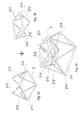
- the support base 2 of the present invention is shown, according to a preferred variant embodiment, in Figures 3a to 3c .
- the polygonal frames 21 have the same shape and/or the same number of edges and/or sides and/or vertices, thereby being geometrically similar, each polygonal frame 21 being scaled to the sizes of the rest of the polygonal frames 21.
- the polygonal frame 21 as shown in Figures 3a to 3c has a triangular shape, and has a base tubular element 211 connected at its ends to two respective inclined tubular elements 212 joined together at a corresponding vertex 213.
- the base tubular element 211 is connected to the two inclined tubular elements 212 at corresponding vertices 214, but the inclined tubular elements 212 may be connected to the base tubular element 211 along its entire length.
- the support base 2 of the figures is composed of 4 polygonal frames 21, which are joined together to form a square polygonal base, although this embodiment shall be intended without limitation, with any number of polygonal frames 21 being possibly joined together, without incurring any particular construction difficulty or obstacle preventing assembly.
- the support base 2 of Figure 3c is composed of two three-dimensional lattice structures, as shown in Figures 3a and 3b respectively, i.e. a lower lattice structure, Figure 3a , and an upper lattice structure, Figure 3b .
- Each of these two lattice structures is formed of four triangular frames 21 joined together by their base vertices 214, so that each lattice structure has a polygonal base consisting of the joined base tubular elements 211 of each triangular frame 21 and has four posts consisting of the inclined tubular elements 212 of each triangular frame 21.
- each lattice structure being joined together so that the bases of each lattice structure are at opposite sides of the support base 2, in the vertical direction, with reference to the vertical center axis thereof.
- the two lattice structures of Figures 3a and 3b are joined together so that the two corresponding polygonal bases are on parallel planes, and are rotated relative to each other with respect to the vertical center axis of the support base 2.
- Figure 3c shows the entire base 2 of the present invention, where the two lattice structures are fixed together so that the vertices 214 of the polygonal base of the lattice structure of Figure 3a are connected to corresponding joined vertices 213 of the inclined tubular elements 212 of the lattice structure of Figure 3b .
- the polygonal bases of the two lattice structures are arranged in parallel relationship at opposite sides of said support base, in the vertical direction, with reference to the vertical center axis of said support base.
- the polygonal bases are rotated relative to each other and, considering the regular square shape of such polygonal bases, the rotation angle will be 45°.
- the inclined tubular elements 212 of the lower lattice structure of Figure 3a are preferably oriented perpendicular to their polygonal base, the upper polygonal base, i.e. the one that belongs to the lattice structure of Figure 3b , will be smaller than the lower polygonal base.
- Figure 3c shows a plate 3 which is adapted to increase the stiffness of the entire support base 2 by joining the vertices 213 of the oblique tubular elements 212 of the upper lattice structure.
- such vertices 213 converge toward the plate 3.
- such plate 3 may consist of a support plate for the fifth wheel that transfers the action of the electric motor to the rotating carousel 11.
- the electric motor may be located in any position, either above or below the fifth wheel supporting plate 3.
- the tubular elements preferably have a square section, although common types of prior art profile may be provided.
- the sections of the tubular elements may be modified, using different sections also within the same base.
- tubular elements 211 that form the lower polygonal base and the upper polygonal base have a larger section than the oblique tubular elements 212, to impart greater stiffness to the whole structure.
- the triangular frames 21 are preferably joined together by bonding, using a similar structural adhesive.
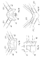
- Figure 4 shows the triangular frames 21 joined together at their vertices 213 and 214 through fixing joints 4 that have interface surfaces adapted to interact with the sections of the tubular elements 211 and 212.
- the fixing interfaces overlap the inner or outer surfaces of the end sections of the tubular elements 211 and 212, thereby creating contact surfaces for receiving the adhesive material therebetween.
- the fixing joints 4 have as many interface surfaces as there are triangular frames 21 to be joined.
- Fixing joints 4 are also provided for fixing the four vertices 213 of the upper lattice structure to the support plate 31 of the fifth wheel.
- FIGS 5a to 5d show various details of such fixing joints 3.
- the fixing joints may be even unnecessary in particular exemplary embodiments, e.g. when welding is used for joining the tubular elements and/or between the polygonal frames formed thereby.
- the fixing joints are composed of a first stationary part 41 and a second movable part 42.
- the first stationary part 41 is composed of surfaces 411 that are connected together, each surface 411 being designed to be placed in contact with the section of the tubular element 211, and having an aperture at such section, having the same size as it.
- the second part 42 consists of box-like elements whose section allows them to be fitted into the aperture of the surfaces 411 and into the section of the tubular elements 211 and 212, such box-like elements having an abutment surface for abutment against the surfaces 411.
- Figure 5a shows a fixing joint for joining two tubular base elements 211 of the triangular frame 211, which joint has two interface surfaces for interfacing therewith, with 2 apertures for receiving the tubular element 211 of the box-like element 42, with the abutment head of the latter, abutting against the surface 411, being only shown in Figure 5a .
- Figure 5b shows a fixing joint 4 for joining two base tubular elements 211 and the vertex 213 of the two inclined tubular elements 212, such joint hence having three interface surfaces 411.
- Figure 5c shows the box-like element 42 once it has been inserted in the tubular element 211 and 211 through the aperture of the interface surface 411, such that the adhesive material may be interposed between the outer shell surface of the box-like element 42 and the inner surface of the tubular element 211 and 212.
- the interface surfaces of the joint are welded to the end part of the tubular elements 211 and 212, and the inclined tubular element 212 is also preferably welded to the base tubular element 211.
- Figure 5d shows another possible type of fixing joints that may be used for joining the polygonal frames and/or the tubular elements belonging to the operating machine of the present invention.
- the first part 41 and the second part 42 are formed of one piece 5, preferably obtained by precision casting.
- Figure 6 shows a variant embodiment of the support base 2 of the present invention.
- the three-dimensional lattice structure 3 consists of a central part 31 and a peripheral part 32.
- the central part 31 is formed as a tower by arranging side by side a plurality of modular elements, which have a lattice form, i.e. each modular element consists of two elongate elements 311 arranged in parallel and spaced relation along the vertical center axis of the three-dimensional lattice structure 3, connection elements 312 being provided for connecting the two elongate elements 311.
- Figures 7a and 7b particularly show the central part 31 and the peripheral part 32 respectively.
- the central part 31 is composed of 4 modular elements arranged side by side along their respective elongate elements 311.
- connection elements 312 may be used, even different numbers, according to the modular element in the same structure.
- the central part 31 is composed of 2 facing modular elements which have a large number of connection elements 312 and two further modular elements having a smaller number of connection elements 312 than the previous ones.
- the central part 31 is joined to a given number of stabilizing modules 32, 8 modules in the illustrated example, i.e. two for each vertex of the central polygonal tower having a square base.
- the eight stabilizing modules 32 preferably consist of trapezoidal elements which extend outwards from the adjacent surfaces of the elongate elements 311.
- a smaller number of modules may be also provided, with one module only being provided for each corner area, or even a larger number may be provided, possibly when the central tower has a triangular base or a polygonal base with more than four corners.
- the above configuration is particularly advantageous, as it affords extensive height adjustment, due to the possibility of superimposing various central parts 31 and as many stabilizing modules 32, while maintaining the stability and stiffness of the system, as shown in Figure 7c .
- the stabilizing modules may consist of simple tubular elements, each consisting of a single elongate element adapted to discharge part of the weight applied to the support base 2.
- Such elongate elements may be provided in any shape, size and number:
- Figure 8 shows a possible embodiment, having a central part 31 as illustrated in Figure 6 and stabilizing modules 33 consisting of said elongate elements.
- FIGS 9a to 9c show a possible variant embodiment of the operating machine of the present invention.
- the operating machine is embodied by a rotary machine for bottling lines, such as a rinser, a sterilizer or the like, with the operating part comprising a rotating carousel 11 driven by at least one electric motor 44, such that the support carousel 11 rotates about its own vertical center axis.
- the support base 2 consists of a support frame 4 comprising at least two columns 41 joined together by a superstructure 42.
- the carousel 11 is also supported by the second support base part, so that it hangs from the support frame 4, particularly from the superstructure 42.
- the support frame 4 may be formed with the structural and construction characteristics as described concerning one or more of the general or specific examples of the base.
- Figures 9b and 9c show two perspective views of possible embodiments of the support frame 4, according to the above described characteristics.
- the support frame 4 is formed of lattice elements, i.e. modular elements consisting of two elongate elements 411 arranged in parallel relationship and interconnected by connection elements 412.
- Figure 9b clearly shows that further embodiments may be also provided, using all the variants of the modular elements as described above, e.g. the various shapes of the polygonal frames, such as a polygonal rectangular frame, or a triangular frame as shown in Figure 9c , where the triangular frames consist of tubular elements 413 having the above described characteristics.
- the various shapes of the polygonal frames such as a polygonal rectangular frame, or a triangular frame as shown in Figure 9c , where the triangular frames consist of tubular elements 413 having the above described characteristics.
- a support frame 4 may have polygonal frames of different shapes therein.
- the construction of the base may also apply to the bearing framework of the operating units of the operating part.
- the latter comprises a carousel, which consists of a circular frame supported to rotate about its axis on the base, and is rotatably driven by a motor.
- the rotating frame of the carousel carries a plurality of operating units, which consist of bottle grippers, means for overturning and moving bottles to the nozzles that spray washing, rinsing and/or drying fluids, and means for overturning them back to the standing position.
- the carousel frame is formed with the structural and construction characteristics as described concerning one or more of the general or specific examples of the base.
- Figures 10a to 10d show two different embodiments of the fixing joints that connect two or more tubular elements.
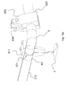
- the fixing joints connect the end of a first tubular element 215 to the end of a second tubular element 216 through a connection element 6, that is connected by its two end sides to the first tubular element 215 and the second tubular element 216 by means of a first fixing member 61 and a second fixing member 62 respectively.
- connection element may have any section and shape, although it will preferably have a circular section and will be in the form of a corner tubular element, for easier connection of the first tubular element 215 and the second tubular element 216.
- connection element 6 may be designed to be fitted into the terminals of the first 215 and second 216 tubular elements, whereupon they will be fixed in position by the first 61 and second 62 fixing members.
- terminals of the first 215 and second 216 tubular elements may be designed to be fitted into the end sides of the connection element 6.
- connection element 6 may be formed with the same section sizes as the terminals of the tubular elements 215 and 216.
- an inner joint 63 will be preferably provided which has a slightly smaller section than the end side of the connection element 6 and/or the terminals of the tubular elements 215 and 216.
- the inner joint 63 is fitted partly into the terminal of the tubular element 215 or 216, and partly into the end sides of the connection element 6, for the connection element 6 to be aligned with the tubular elements 215 and 216.
- the inner joint 63 may have an intermediate flange 831, which is formed by radial enlargement of the joint, such intermediate flange having the same section as the tubular element and the connection element, so that, in the assembled state, such radial enlargement is flush with the outer wall of the tubular element and the connection element 6.
- an adhesive layer is provided between the outer surface of the inner joint 63 and the inner surface of the end sides and the tubular elements 215 and 216.
- first fixing member 61 and/or the second fixing member 62 allow connection of a third tubular member 217, such that the third tubular element 217 is moved relative to the first 215 and second 216 tubular elements with at least one degree of freedom.
- bearing feet 7 of the base may be connected to the fixing members 61 and/or 62, as shown in Figures 10a to 10e .
- the fixing joint has the above described characteristics and, additionally, the first fixing member 61 is composed of two half-collars 611, which are clamped together to form an inner clamping surface for fixing an end side of the connection element 6 to the end of the first tubular element 215.
- the second fixing member 62 is composed of two jaws 621, which are clamped together to form an inner clamping surface for fixing an end side of the connection element 6 to the end of the second tubular element 216.
- the two clamped jaws 621 form a hemispherical seat for facilitated reception of a spherical head 622, which is preferably connected by bonding to the third tubular element 217.
- Figure 10b shows a detail of the second fixing member 2, in which the two jaws 621 are in a coupled state and form a seat consisting of a continuous surface having an angular amplitude of more than 180°, such that the spherical head 622 may be press-fitted into and held by the two jaws 621, i.e. the housing surface lies on the outer surface of the spherical head 622 beyond the maximum diameter area of the sphere.
- the spherical head 622 is bonded to a terminal of the tubular element 217 as shown in the figure, and is rotatably accommodated to allow the third tubular element 217 to move relative to the tubular elements 215 and 216.
- lock means are preferably provided for locking the rotation of the spherical head 622.
- any fastening means may be provided for coupling thereof, either of mechanical type such as by screws, or of chemical type, such as bonding.
- Figures 10c and 10d show a further embodiment of the fixing joint, where the first fixing member 61 is composed of two half-collars 611, which are clamped together to form an inner clamping surface for fixing an end side of the connection element 6 to the end of the first tubular element 215, in the same fashion as shown in Figures 10a and 10b .
- the second fixing member 62 is composed of two jaws 623, which are clamped together to form an inner clamping surface for fixing an end side of the connection element 6 to the end of the second tubular element 216.
- Each jaw 623 extends in the vertical direction such that, when said two jaws 623 are clamped together, they form a seat for receiving the end element 624 connected by bonding to the third tubular element 217.
- Both the end element 624 and the jaws 623 include a hole 625, for receiving a pin and a screw which are designed to hold the end element 624 in the seat formed by the two jaws 623.
- the pin prevents any translational motion of the end element 623, but allows rotation thereof about the axis of the pin, thereby allowing the tubular element 217 to move relative to the tubular elements 215 and 216.
- the screw also prevents any translational motion of the end element 623 and allows rotation thereof about the axis of the screw, but due to the provision of threads in the holes 625, it allows the end element 623 to be locked in its position once the screw has been tightened in the holes 625.
- the end element 623 is bonded to a terminal of the third tubular element 217 and the half-collars 611 are also bonded to retain the end side of the connection element and the terminal of the tubular element 215.
- Figure 10e is an exploded view of the fixing joint, that shows the inner joint 63 inserted between the end sides of the connection element 6 and the first 215 and second 216 tubular elements.
- the figure also shows the first fixing member 61, which is composed of two half-collars 611 coupled together by fastening pins and later joined to the foot 7.
- an adhesive may be used both to fasten the inner joint 63 to the tubular elements 215 and 216 and to join the half-collars 611 together and/or fasten them to the tubular elements.
- Figures 11a and 11b show that the above fixing joint may be used to join the various tubular elements by providing a variant embodiment of the base of the present invention, as described above.
- the fixing joints 4 connect the end of a first tubular element 215 to the end of a second tubular element 216 through a connection element 6, that is connected by its two end sides to the first tubular element and the second tubular element.
- connection element 6 has a fixing member 62 for connecting at least one third tubular element 217, here two.
- each tubular element 217 moves relative to the first 215 and second 216 tubular elements.
- Figure 10b is an exploded view of the fixing joint 4, which especially shows the use of the inner joint 63 for connecting the tubular elements 215 and 216 to the end sides of the connection element 6.
- Figures 12a to 12d show a variant embodiment of the fixing joints, with different numbers and orientations of the tubular elements.
- connection elements 6 are not only provided at the corners of the base, but also along straight parts.
Landscapes
- Engineering & Computer Science (AREA)
- General Engineering & Computer Science (AREA)
- Mechanical Engineering (AREA)
- Eye Examination Apparatus (AREA)
- Centrifugal Separators (AREA)
- Standing Axle, Rod, Or Tube Structures Coupled By Welding, Adhesion, Or Deposition (AREA)
Applications Claiming Priority (1)
| Application Number | Priority Date | Filing Date | Title |
|---|---|---|---|
| IT000098A ITGE20110098A1 (it) | 2011-09-02 | 2011-09-02 | Macchina operatrice |
Publications (1)
| Publication Number | Publication Date |
|---|---|
| EP2565126A1 true EP2565126A1 (fr) | 2013-03-06 |
Family
ID=44860466
Family Applications (1)
| Application Number | Title | Priority Date | Filing Date |
|---|---|---|---|
| EP12182685A Ceased EP2565126A1 (fr) | 2011-09-02 | 2012-08-31 | Machine opérante |
Country Status (2)
| Country | Link |
|---|---|
| EP (1) | EP2565126A1 (fr) |
| IT (1) | ITGE20110098A1 (fr) |
Cited By (1)
| Publication number | Priority date | Publication date | Assignee | Title |
|---|---|---|---|---|
| CN106269711A (zh) * | 2016-08-26 | 2017-01-04 | 江苏新美星包装机械股份有限公司 | 干式冲瓶装置 |
Citations (8)
| Publication number | Priority date | Publication date | Assignee | Title |
|---|---|---|---|---|
| US4626299A (en) * | 1985-06-24 | 1986-12-02 | The Warner & Swasey Company | Method of attaching guideways to a machine tool bed |
| EP0589565A2 (fr) * | 1992-09-18 | 1994-03-30 | The Ingersoll Milling Machine Company | Machine ayant le forme d'un octohèdre avec une partie en triangle comprenant six entretoises servocommandées |
| US5920974A (en) * | 1997-05-15 | 1999-07-13 | Northrop Grumman Corporation | Reconfigurable gantry tool and system |
| EP1149957A2 (fr) * | 2000-03-02 | 2001-10-31 | Fennotek Oy | Système de barres profilées |
| WO2002051706A1 (fr) * | 2000-12-22 | 2002-07-04 | Aautomag S.R.L. | Systeme modulaire constitue par une construction de profiles en acier pour chaine d'emballage |
| US20090071105A1 (en) * | 2007-09-17 | 2009-03-19 | Zoran Momich | Apparatus and method for a carton carrier |
| WO2010013263A1 (fr) * | 2008-07-29 | 2010-02-04 | Sidel S.P.A. | Structure de support modulaire et module de celle-ci pour machines de manipulation de conteneurs |
| DE102009042014A1 (de) * | 2009-09-21 | 2011-03-24 | Dürr Systems GmbH | Handhabungsvorrichtung |
-
2011
- 2011-09-02 IT IT000098A patent/ITGE20110098A1/it unknown
-
2012
- 2012-08-31 EP EP12182685A patent/EP2565126A1/fr not_active Ceased
Patent Citations (8)
| Publication number | Priority date | Publication date | Assignee | Title |
|---|---|---|---|---|
| US4626299A (en) * | 1985-06-24 | 1986-12-02 | The Warner & Swasey Company | Method of attaching guideways to a machine tool bed |
| EP0589565A2 (fr) * | 1992-09-18 | 1994-03-30 | The Ingersoll Milling Machine Company | Machine ayant le forme d'un octohèdre avec une partie en triangle comprenant six entretoises servocommandées |
| US5920974A (en) * | 1997-05-15 | 1999-07-13 | Northrop Grumman Corporation | Reconfigurable gantry tool and system |
| EP1149957A2 (fr) * | 2000-03-02 | 2001-10-31 | Fennotek Oy | Système de barres profilées |
| WO2002051706A1 (fr) * | 2000-12-22 | 2002-07-04 | Aautomag S.R.L. | Systeme modulaire constitue par une construction de profiles en acier pour chaine d'emballage |
| US20090071105A1 (en) * | 2007-09-17 | 2009-03-19 | Zoran Momich | Apparatus and method for a carton carrier |
| WO2010013263A1 (fr) * | 2008-07-29 | 2010-02-04 | Sidel S.P.A. | Structure de support modulaire et module de celle-ci pour machines de manipulation de conteneurs |
| DE102009042014A1 (de) * | 2009-09-21 | 2011-03-24 | Dürr Systems GmbH | Handhabungsvorrichtung |
Non-Patent Citations (3)
| Title |
|---|
| R. J. HUSSEY, JOSEPHINE WILSON: "Structural Adhesives", 31 December 1996, CHAPMAN & HALL, London [UK], ISBN: 0 412 71470 1 * |
| SUH J D ET AL: "Composite Machine Tool Structures for High Speed Milling Machines", CIRP ANNALS, ELSEVIER BV, NL, CH, FR, vol. 51, no. 1, 1 January 2002 (2002-01-01), pages 285 - 288, XP027601342, ISSN: 0007-8506, [retrieved on 20020101], DOI: 10.1016/S0007-8506(07)61518-2 * |
| SWIFT K.G., BOOKER J.D.: "Process Selection. From design to manufacture. Second edition.", REFEREX, 31 December 2003 (2003-12-31), Oxford, XP040425364, ISBN: 0 7506 5437 6 * |
Cited By (1)
| Publication number | Priority date | Publication date | Assignee | Title |
|---|---|---|---|---|
| CN106269711A (zh) * | 2016-08-26 | 2017-01-04 | 江苏新美星包装机械股份有限公司 | 干式冲瓶装置 |
Also Published As
| Publication number | Publication date |
|---|---|
| ITGE20110098A1 (it) | 2013-03-03 |
Similar Documents
| Publication | Publication Date | Title |
|---|---|---|
| TWI580541B (zh) | 並聯式機器人及線性並聯式機構 | |
| KR102439616B1 (ko) | 범용성을 가진 용접용 지그 | |
| US9642458B2 (en) | Fixing device | |
| KR20150084985A (ko) | 6-자유도 모션 시뮬레이터 어셈블리 | |
| EP2565126A1 (fr) | Machine opérante | |
| CN108340198B (zh) | 一种面向大型复杂结构件的吸附式加工装置 | |
| WO2017098699A1 (fr) | Dispositif d'assemblage et son procédé de commande | |
| JP2011529426A (ja) | 容器処理装置で用いられるモジュール式支持構造体及び該支持構造体を構成するモジュール | |
| EP3137778A1 (fr) | Rouleau d'un aménagement de support pour plate-forme de traite rotative | |
| CN215865715U (zh) | 一种用于振动台的扶正装置及振动系统 | |
| KR102059632B1 (ko) | 워크 위치 결정장치 | |
| WO2017010439A1 (fr) | Véhicule aérien sans pilote | |
| JP4660849B2 (ja) | 容器処理機とスターホイール式容器搬送機との結合構造 | |
| KR20140042337A (ko) | 흡착 테이블 장치 | |
| JP6022889B2 (ja) | 振動式ボウルフィーダ | |
| WO1999003650A1 (fr) | Robot industriel | |
| CN102781739B (zh) | 用于支撑侧面清洗刷的设备和具有该设备的车辆清洗系统 | |
| KR20150133967A (ko) | 기판 스피닝 장치의 회전 지지대 | |
| JP2012011501A (ja) | 生産システム | |
| CN109303528B (zh) | 轮体缓冲调节机构及扫地机器人 | |
| EP1795466A1 (fr) | Convoyeur vibrant | |
| JP4081058B2 (ja) | トグル制振装置の連結構造 | |
| EP2582611B1 (fr) | Structure support pour des installations de manutention de contenants | |
| CN114946109A (zh) | 用于回转调节机构的回转体和致动器 | |
| US11858747B2 (en) | Vibratory conveyors having mounting plates |
Legal Events
| Date | Code | Title | Description |
|---|---|---|---|
| PUAI | Public reference made under article 153(3) epc to a published international application that has entered the european phase |
Free format text: ORIGINAL CODE: 0009012 |
|
| AK | Designated contracting states |
Kind code of ref document: A1 Designated state(s): AL AT BE BG CH CY CZ DE DK EE ES FI FR GB GR HR HU IE IS IT LI LT LU LV MC MK MT NL NO PL PT RO RS SE SI SK SM TR |
|
| AX | Request for extension of the european patent |
Extension state: BA ME |
|
| 17P | Request for examination filed |
Effective date: 20130905 |
|
| 17Q | First examination report despatched |
Effective date: 20140307 |
|
| APBK | Appeal reference recorded |
Free format text: ORIGINAL CODE: EPIDOSNREFNE |
|
| APBN | Date of receipt of notice of appeal recorded |
Free format text: ORIGINAL CODE: EPIDOSNNOA2E |
|
| APBR | Date of receipt of statement of grounds of appeal recorded |
Free format text: ORIGINAL CODE: EPIDOSNNOA3E |
|
| APAF | Appeal reference modified |
Free format text: ORIGINAL CODE: EPIDOSCREFNE |
|
| APBT | Appeal procedure closed |
Free format text: ORIGINAL CODE: EPIDOSNNOA9E |
|
| STAA | Information on the status of an ep patent application or granted ep patent |
Free format text: STATUS: THE APPLICATION HAS BEEN REFUSED |
|
| 18R | Application refused |
Effective date: 20220506 |