EP2565415B1 - Dispositif sur un moteur à combustion interne - Google Patents
Dispositif sur un moteur à combustion interne Download PDFInfo
- Publication number
- EP2565415B1 EP2565415B1 EP12004099.3A EP12004099A EP2565415B1 EP 2565415 B1 EP2565415 B1 EP 2565415B1 EP 12004099 A EP12004099 A EP 12004099A EP 2565415 B1 EP2565415 B1 EP 2565415B1
- Authority
- EP
- European Patent Office
- Prior art keywords
- line
- manifold
- restriction
- inlet
- header
- Prior art date
- Legal status (The legal status is an assumption and is not a legal conclusion. Google has not performed a legal analysis and makes no representation as to the accuracy of the status listed.)
- Active
Links
Images
Classifications
-
- F—MECHANICAL ENGINEERING; LIGHTING; HEATING; WEAPONS; BLASTING
- F02—COMBUSTION ENGINES; HOT-GAS OR COMBUSTION-PRODUCT ENGINE PLANTS
- F02M—SUPPLYING COMBUSTION ENGINES IN GENERAL WITH COMBUSTIBLE MIXTURES OR CONSTITUENTS THEREOF
- F02M35/00—Combustion-air cleaners, air intakes, intake silencers, or induction systems specially adapted for, or arranged on, internal-combustion engines
- F02M35/10—Air intakes; Induction systems
- F02M35/10242—Devices or means connected to or integrated into air intakes; Air intakes combined with other engine or vehicle parts
- F02M35/10295—Damping means, e.g. tranquillising chamber to dampen air oscillations
-
- F—MECHANICAL ENGINEERING; LIGHTING; HEATING; WEAPONS; BLASTING
- F02—COMBUSTION ENGINES; HOT-GAS OR COMBUSTION-PRODUCT ENGINE PLANTS
- F02B—INTERNAL-COMBUSTION PISTON ENGINES; COMBUSTION ENGINES IN GENERAL
- F02B27/00—Use of kinetic or wave energy of charge in induction systems, or of combustion residues in exhaust systems, for improving quantity of charge or for increasing removal of combustion residues
- F02B27/005—Oscillating pipes with charging achieved by arrangement, dimensions or shapes of intakes pipes or chambers; Ram air pipes
-
- F—MECHANICAL ENGINEERING; LIGHTING; HEATING; WEAPONS; BLASTING
- F02—COMBUSTION ENGINES; HOT-GAS OR COMBUSTION-PRODUCT ENGINE PLANTS
- F02B—INTERNAL-COMBUSTION PISTON ENGINES; COMBUSTION ENGINES IN GENERAL
- F02B27/00—Use of kinetic or wave energy of charge in induction systems, or of combustion residues in exhaust systems, for improving quantity of charge or for increasing removal of combustion residues
- F02B27/008—Resonance charging
-
- F—MECHANICAL ENGINEERING; LIGHTING; HEATING; WEAPONS; BLASTING
- F02—COMBUSTION ENGINES; HOT-GAS OR COMBUSTION-PRODUCT ENGINE PLANTS
- F02M—SUPPLYING COMBUSTION ENGINES IN GENERAL WITH COMBUSTIBLE MIXTURES OR CONSTITUENTS THEREOF
- F02M26/00—Engine-pertinent apparatus for adding exhaust gases to combustion-air, main fuel or fuel-air mixture, e.g. by exhaust gas recirculation [EGR] systems
- F02M26/13—Arrangement or layout of EGR passages, e.g. in relation to specific engine parts or for incorporation of accessories
- F02M26/17—Arrangement or layout of EGR passages, e.g. in relation to specific engine parts or for incorporation of accessories in relation to the intake system
- F02M26/19—Means for improving the mixing of air and recirculated exhaust gases, e.g. venturis or multiple openings to the intake system
-
- F—MECHANICAL ENGINEERING; LIGHTING; HEATING; WEAPONS; BLASTING
- F02—COMBUSTION ENGINES; HOT-GAS OR COMBUSTION-PRODUCT ENGINE PLANTS
- F02M—SUPPLYING COMBUSTION ENGINES IN GENERAL WITH COMBUSTIBLE MIXTURES OR CONSTITUENTS THEREOF
- F02M35/00—Combustion-air cleaners, air intakes, intake silencers, or induction systems specially adapted for, or arranged on, internal-combustion engines
- F02M35/10—Air intakes; Induction systems
- F02M35/10242—Devices or means connected to or integrated into air intakes; Air intakes combined with other engine or vehicle parts
- F02M35/10308—Equalizing conduits, e.g. between intake ducts or between plenum chambers
-
- F—MECHANICAL ENGINEERING; LIGHTING; HEATING; WEAPONS; BLASTING
- F02—COMBUSTION ENGINES; HOT-GAS OR COMBUSTION-PRODUCT ENGINE PLANTS
- F02M—SUPPLYING COMBUSTION ENGINES IN GENERAL WITH COMBUSTIBLE MIXTURES OR CONSTITUENTS THEREOF
- F02M35/00—Combustion-air cleaners, air intakes, intake silencers, or induction systems specially adapted for, or arranged on, internal-combustion engines
- F02M35/10—Air intakes; Induction systems
- F02M35/104—Intake manifolds
- F02M35/112—Intake manifolds for engines with cylinders all in one line
-
- F—MECHANICAL ENGINEERING; LIGHTING; HEATING; WEAPONS; BLASTING
- F02—COMBUSTION ENGINES; HOT-GAS OR COMBUSTION-PRODUCT ENGINE PLANTS
- F02M—SUPPLYING COMBUSTION ENGINES IN GENERAL WITH COMBUSTIBLE MIXTURES OR CONSTITUENTS THEREOF
- F02M35/00—Combustion-air cleaners, air intakes, intake silencers, or induction systems specially adapted for, or arranged on, internal-combustion engines
- F02M35/12—Intake silencers ; Sound modulation, transmission or amplification
- F02M35/1255—Intake silencers ; Sound modulation, transmission or amplification using resonance
- F02M35/1261—Helmholtz resonators
-
- Y—GENERAL TAGGING OF NEW TECHNOLOGICAL DEVELOPMENTS; GENERAL TAGGING OF CROSS-SECTIONAL TECHNOLOGIES SPANNING OVER SEVERAL SECTIONS OF THE IPC; TECHNICAL SUBJECTS COVERED BY FORMER USPC CROSS-REFERENCE ART COLLECTIONS [XRACs] AND DIGESTS
- Y02—TECHNOLOGIES OR APPLICATIONS FOR MITIGATION OR ADAPTATION AGAINST CLIMATE CHANGE
- Y02T—CLIMATE CHANGE MITIGATION TECHNOLOGIES RELATED TO TRANSPORTATION
- Y02T10/00—Road transport of goods or passengers
- Y02T10/10—Internal combustion engine [ICE] based vehicles
- Y02T10/12—Improving ICE efficiencies
Definitions
- the present invention relates to a device on an internal combustion engine with at least one charge air manifold according to the preamble of patent claim 1.
- a device of the generic type shows, for example, the US Pat. No. 2,080,293 in which, in a mixture-compressing series internal combustion engine on the charge air manifold or along the cylinder extending manifold at a location further away from a confluence of the combustion air a return line is connected, which returns the intake combustion air via an integrated throttle point back to the mouth of the manifold (short-circuit flow ).
- This is to ensure that interfering air vibrations due to the opening and closing of the gas exchange valves smoothed and the degree of filling in particular the further removed from the junction at the manifold cylinder of the internal combustion engine is improved.
- the publication DE 197 41 567 A1 teaches a reciprocating internal combustion engine with a longitudinally extending to a row of cylinders charge air line for supplying the combustion chambers with charge air. At a closed end of the charge air duct is provided a volume which increases its volume by an additional volume of air in order to equalize the air supply.
- the object of the invention is to further improve the generic device with structurally simple means and adapt to operating conditions of internal combustion engines high, specific performance.
- At least one vibration tube with a defined resonance volume for smoothing and / or displacement of defined or predetermined specific pressure peaks be connected to the manifold, which can also be referred to as manifold. It was inventively recognized that using this further measure improved tuning in Oscillation behavior of the air currents and a further optimized, more uniform filling of the nearer and further away from the inflow of the combustion air in the charge air manifold cylinder is achievable.
- the oscillating pipe can be connected to the collecting pipe in the region of the branching point of the return line, which in addition to structural advantages, for example the saving of an additional connection point to be sealed, also measurable improvements in the filling of one or more of the disadvantaged cylinder with respect to the air distribution, in particular for example of the cylinder (s) farthest from the confluence of the charge manifold manifold. It may be displayed depending on the structural conditions but also other positioning and possibly the arrangement of several swing tubes.
- the internal combustion engine has a throttle point positioned upstream of the confluence, to which an exhaust gas recirculation line is connected, wherein the return line is likewise connected to this throttle point.
- the throttle point for the exhaust gas recirculation can have an adjustable throttle element (for example a Venturi cone) and the return line can be connected downstream of the throttle element to the throttle point.
- the internal combustion engine is provided with a charging system for the combustion air in which the confluence may be preceded by a charge pressure line in the manifold, in which the throttle point for the exhaust gas recirculation and the return line are arranged.
- the charge pressure line may have a conically widening to the mouth of the manifold, tubular mixer section, wherein the throttle point is positioned upstream of the mixer line.
- the manifold and the mixer section of the charge pressure line and a connecting supply line and the return line can advantageously in the Seen in plan view form substantially a rectangle and / or a loop, for example, could be provided that the at least one vibration tube is laid within these lines.
- the vibrating tube can basically be arranged in any other suitable position.
- the air flow in the manifold deflecting deflector may be arranged, which represents another, structurally simple correction element to achieve a uniform degree of filling of all cylinders of the engine and over wide operating ranges thereof.
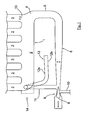
- the schematic drawing shows roughly schematically and merely by way of example a plan view of the charge air manifold and a boost pressure line of a supercharged internal combustion engine having a return line connecting both lines and an integrated vibration tube.
- a charge air manifold 1 is shown, which is flanged to the cylinder head (not shown) of a diesel operated multi-cylinder internal combustion engine.
- the charge air manifold 1 is composed essentially of a rectilinear manifold 2 and branching off individual pipes or individual lines 3 and on the one hand has a junction 4, to which a charge line 6 is connected via a connecting line 5.
- the individual lines 3 are connected in the usual way to gas exchange valves controlled intake ports in the cylinder head of the internal combustion engine or form such inlet channels.
- the combustion air to the combustion chambers of the internal combustion engine is conveyed via a supercharging system (eg one or more exhaust gas turbochargers) via the charge pressure line 6 to the charge air manifold 1.
- a supercharging system eg one or more exhaust gas turbochargers
- a throttle point 8 is provided upstream of a conical mixer section 7, in which a venturi cone 9 is mounted axially displaceable. Via the venturi cone 9, a dynamic pressure reduction in the charge pressure line 6 can be controlled.
- an only indicated exhaust gas recirculation line 10 is connected, via the exhaust by means of an exhaust gas recirculation system, not shown exhaust gas in the pressure-lowered region of the charge pressure line 6 is traceable.
- a return line 11 is connected, on the other hand in the pressure-lowered portion of the throttle point 8, 9 upstream of the mixer line 7 into the charge pressure line 6 opens.
- an end closed swing pipe 12 is connected with a defined resonance volume, which additionally smoothes and / or displaces pressure peaks and gas vibrations occurring in this area.
- the approximately transversely to the manifold 2 branching vibrating tube 12 is - as shown in the single figure is provided here only by way of example with a curvature 12a and within the free space of a rectangle forming lines 2, 11, 6, 5 laid, where it is exemplary here with his End portion 12b extends approximately parallel to the manifold 2 and the charge pressure line 6 in the mixer section 7.
- the position of the at least one vibration tube is arbitrary, because ultimately decides its length on the smoothing or displacement capacity.
- a deflector 13 is arranged, which is a part of the incoming combustion air in the other Discharge manifold 2 with deflects, making this in the present example case in the case of a missing deflector 13 very good and thus supplied with much charge air cylinder "worse" is made and thus to standardize the cylinder filling of all cylinders with less charge air than this without the deflector 13 of Case would be.
- the deflector 13 in conjunction with the function of the return flow 11 and the vibrating tube 12 is designed so that the cylinders of the internal combustion engine as equal as possible degree of filling at lower and higher mass flow rates and operating conditions is achieved.
- the charge air manifold 1 may also be designed so that - as indicated by the arrow 14 - the charge pressure line 6 is connected directly to the left in the image plane end face (dashed lines) of the manifold 2; the return flow line 11 and the vibration tube 12 would then be positioned opposite each other and returned to the throttle point 8, 9 in the charge pressure line 6.
- another branch point from the manifold 2 may be advantageous. It may optionally be used two or more swing tubes 12.
- the only indicated rejection element 13 in the said single line 3 of the charge air manifold 1 can also be curved or designed as a guide wall, possibly also in the region of the junction 4.
- constrictions in the single line 3 or in several individual lines 3 can be used to compensate for different flow resistance.
- the invention can of course be used for a wide variety of types of internal combustion engines, for example, for all existing cylinder banks of an internal combustion engine.
- the invention may be used in conjunction be used with V-type engines or V-type internal combustion engines for a part or preferably for each of the cylinder banks.
Landscapes
- Engineering & Computer Science (AREA)
- Chemical & Material Sciences (AREA)
- Combustion & Propulsion (AREA)
- Mechanical Engineering (AREA)
- General Engineering & Computer Science (AREA)
- Exhaust-Gas Circulating Devices (AREA)
Claims (9)
- Dispositif sur un moteur à combustion interne comprenant au moins un collecteur avec une conduite collectrice (2) et des conduites individuelles (3) en dérivation, par le biais desquelles plusieurs cylindres, disposés en série, du moteur à combustion interne sont alimentés en air de combustion de manière commandée par le biais de soupapes d'échange de gaz, l'air de combustion étant acheminé jusqu'à la conduite collectrice (2) au niveau d'une embouchure (4) proche d'un premier cylindre et étant distribué à d'autres cylindres plus éloignés, et une conduite de retour étant raccordée à la conduite collectrice (2) en au moins un point éloigné de l'embouchure (4), laquelle conduite de retour est à nouveau reliée à l'embouchure ou, en amont de celle-ci, à la conduite collectrice (2) en un point d'étranglement (8, 9) provoquant une baisse de pression, caractérisé en ce que- le collecteur est réalisé sous forme de collecteur d'air de suralimentation (1),- au moins un tuyau à résonance (12) présentant un volume de résonance défini est en outre raccordé à la conduite collectrice (2) pour lisser et/ou pour déplacer des vibrations spécifiques et/ou des pointes de pression de l'air de combustion,- le moteur à combustion interne comprenant, pour réguler une recirculation des gaz d'échappement, un point d'étranglement (8, 9) positionné en amont de l'embouchure (4), auquel point d'étranglement est raccordée une conduite de recirculation des gaz d'échappement (10), et en ce que la conduite de retour (11) est également raccordée à ce point d'étranglement (8, 9).
- Dispositif selon la revendication 1, caractérisé en ce que le tuyau à résonance (12) est raccordé à la conduite collectrice (2) dans la région du point de dérivation de la conduite de retour (11).
- Dispositif selon la revendication 2, caractérisé en ce que le point d'étranglement (8) pour la recirculation des gaz d'échappement comprend un élément d'étranglement réglable (9), et en ce que la conduite de retour (11) est raccordée au point d'étranglement (8) en aval de l'élément d'étranglement (9).
- Dispositif selon l'une quelconque des revendications précédentes, caractérisé en ce que le moteur à combustion interne est pourvu d'un système de suralimentation pour l'air de combustion, dans lequel système de suralimentation une conduite de pression de suralimentation (6) est placée en amont de l'embouchure (4) dans la conduite collectrice (2), dans laquelle conduite de pression de suralimentation est disposé le point d'étranglement (8, 9) pour la conduite de recirculation des gaz d'échappement (10) et la conduite de retour (11).
- Dispositif selon la revendication 4, caractérisé en ce que la conduite de pression de suralimentation (6) comprend une section de mélange (7) s'élargissant de manière conique en direction de l'embouchure de la conduite collectrice (2).
- Dispositif selon la revendication 4 ou 5, caractérisé en ce que le point d'étranglement (8, 9) est positionné en amont de la section de mélange (7).
- Dispositif selon l'une quelconque des revendications précédentes, caractérisé en ce que la conduite collectrice (2) et la section de mélange (7) de la conduite de pression de suralimentation (6), ainsi qu'une conduite de liaison (5) se raccordant aux deux, y compris la conduite de retour (11), sont réalisées sous forme rectangulaire et/ou sous forme de conduite annulaire en vue de dessus.
- Dispositif selon la revendication 7, caractérisé en ce qu'au moins un tuyau à résonance (12) est placé à l'intérieur de l'espace libre entre ces conduites (2, 5, 6, 11).
- Dispositif selon l'une quelconque des revendications précédentes, caractérisé en ce qu'un élément déflecteur (13) déviant le flux d'air dans la conduite collectrice (2) est disposé au moins dans la conduite individuelle (3) du collecteur d'air de suralimentation (1) située le plus près de l'embouchure (4).
Applications Claiming Priority (1)
| Application Number | Priority Date | Filing Date | Title |
|---|---|---|---|
| DE102011112187A DE102011112187A1 (de) | 2011-09-01 | 2011-09-01 | Vorrichtung an einer Brennkaftmaschine |
Publications (2)
| Publication Number | Publication Date |
|---|---|
| EP2565415A1 EP2565415A1 (fr) | 2013-03-06 |
| EP2565415B1 true EP2565415B1 (fr) | 2015-02-11 |
Family
ID=46245443
Family Applications (1)
| Application Number | Title | Priority Date | Filing Date |
|---|---|---|---|
| EP12004099.3A Active EP2565415B1 (fr) | 2011-09-01 | 2012-05-26 | Dispositif sur un moteur à combustion interne |
Country Status (2)
| Country | Link |
|---|---|
| EP (1) | EP2565415B1 (fr) |
| DE (1) | DE102011112187A1 (fr) |
Families Citing this family (1)
| Publication number | Priority date | Publication date | Assignee | Title |
|---|---|---|---|---|
| CN108457765B (zh) * | 2018-02-07 | 2020-06-26 | 广西玉柴机器股份有限公司 | 气体机进气道 |
Family Cites Families (3)
| Publication number | Priority date | Publication date | Assignee | Title |
|---|---|---|---|---|
| US2080293A (en) | 1933-10-24 | 1937-05-11 | Whatmough Wilfred Ambrose | Means for automatically modifying the flow of pulsating fluid flow streams |
| DE4215417A1 (de) * | 1992-05-11 | 1993-11-18 | Porsche Ag | Luftansaugvorrichtung für eine Brennkraftmaschine |
| DE19741567B4 (de) * | 1997-09-20 | 2005-12-08 | Man B & W Diesel Ag | Hubkolben-Brennkraftmaschine |
-
2011
- 2011-09-01 DE DE102011112187A patent/DE102011112187A1/de not_active Withdrawn
-
2012
- 2012-05-26 EP EP12004099.3A patent/EP2565415B1/fr active Active
Also Published As
| Publication number | Publication date |
|---|---|
| EP2565415A1 (fr) | 2013-03-06 |
| DE102011112187A1 (de) | 2013-03-07 |
Similar Documents
| Publication | Publication Date | Title |
|---|---|---|
| EP2362083B1 (fr) | Procédé et dispositif destinés a commander un moteur à combustion interne d'un véhicule automobile | |
| EP2456969B1 (fr) | Moteur à combustion interne et installation d'air frais | |
| EP2057362B1 (fr) | Dispositif et procede d'alimentation en air frais d'un moteur a combustion interne a pistons suralimente | |
| EP2370687B1 (fr) | Machine à combustion interne | |
| DE102010048473B4 (de) | Turbolader | |
| DE102016214954A1 (de) | Gasförmiger Brennstoff, AGR und Luftmischvorrichtung plus Einsatz | |
| DE102010032363A1 (de) | AGR-Entnahme unmittelbar stromabwärts eines vor einem Turbo befindlichen Katalysators | |
| DE102012211614A1 (de) | System für einen ladeluftkühler | |
| EP2179153B1 (fr) | Moteur à combustion interne | |
| DE102017125876A1 (de) | Kraftstoffeinspritzvorrichtung mit variabler Strömungsrichtung | |
| DE102009000214A1 (de) | Brennkraftmaschine mit Abgasturboaufladung | |
| DE10224719A1 (de) | Einrichtung und Verfahren zum Speisen von Zylindern von aufgeladenen Verbrennungsmotoren | |
| DE102013220026A1 (de) | Einlasskrümmer mit AGR für Zweifachdurchlass | |
| DE60131161T2 (de) | Verfahren und vorrichtung zur abgasrückgewinnung und eine aufgeladene dieselkraftmaschine | |
| DE102013212904A1 (de) | Brennkraftmaschine | |
| EP2565415B1 (fr) | Dispositif sur un moteur à combustion interne | |
| DE3529388C2 (fr) | ||
| DE102016106306B4 (de) | Verfahren zum Betreiben einer aufgeladenen Brennkraftmaschine | |
| EP2677156B1 (fr) | Installation d'aspiration pour moteurs à combustion interne | |
| DE102010030793A1 (de) | Spiegelbild-Zylinderköpfe | |
| EP2602468B1 (fr) | Moteur à combustion interne avec système de recirculation de gaz d'échappement | |
| DE102015015536A1 (de) | Brennkraftmaschine mit einer Frischluftanlage, mit einer Abgasanlage und mit mindestens einem Abgasturbolader | |
| DE102013021662A1 (de) | Aufgeladene Brennkraftmaschine | |
| DE102014215364B4 (de) | Brennkraftmaschine | |
| DE102012020443A1 (de) | Abgaskrümmer für eine Brennkraftmaschine, insbesondere in Kraftfahrzeugen |
Legal Events
| Date | Code | Title | Description |
|---|---|---|---|
| PUAI | Public reference made under article 153(3) epc to a published international application that has entered the european phase |
Free format text: ORIGINAL CODE: 0009012 |
|
| AK | Designated contracting states |
Kind code of ref document: A1 Designated state(s): AL AT BE BG CH CY CZ DE DK EE ES FI FR GB GR HR HU IE IS IT LI LT LU LV MC MK MT NL NO PL PT RO RS SE SI SK SM TR |
|
| AX | Request for extension of the european patent |
Extension state: BA ME |
|
| 17P | Request for examination filed |
Effective date: 20130419 |
|
| GRAP | Despatch of communication of intention to grant a patent |
Free format text: ORIGINAL CODE: EPIDOSNIGR1 |
|
| INTG | Intention to grant announced |
Effective date: 20141114 |
|
| RIN1 | Information on inventor provided before grant (corrected) |
Inventor name: TILINSKI, MARCO Inventor name: MALISCHEWSKI, THOMAS Inventor name: HIRSCHMANN, STEFFEN |
|
| GRAS | Grant fee paid |
Free format text: ORIGINAL CODE: EPIDOSNIGR3 |
|
| GRAA | (expected) grant |
Free format text: ORIGINAL CODE: 0009210 |
|
| AK | Designated contracting states |
Kind code of ref document: B1 Designated state(s): AL AT BE BG CH CY CZ DE DK EE ES FI FR GB GR HR HU IE IS IT LI LT LU LV MC MK MT NL NO PL PT RO RS SE SI SK SM TR |
|
| REG | Reference to a national code |
Ref country code: GB Ref legal event code: FG4D Free format text: NOT ENGLISH |
|
| REG | Reference to a national code |
Ref country code: CH Ref legal event code: EP |
|
| REG | Reference to a national code |
Ref country code: IE Ref legal event code: FG4D Free format text: LANGUAGE OF EP DOCUMENT: GERMAN |
|
| REG | Reference to a national code |
Ref country code: AT Ref legal event code: REF Ref document number: 710010 Country of ref document: AT Kind code of ref document: T Effective date: 20150315 |
|
| REG | Reference to a national code |
Ref country code: DE Ref legal event code: R096 Ref document number: 502012002242 Country of ref document: DE Effective date: 20150319 |
|
| REG | Reference to a national code |
Ref country code: SE Ref legal event code: TRGR |
|
| REG | Reference to a national code |
Ref country code: LT Ref legal event code: MG4D |
|
| PG25 | Lapsed in a contracting state [announced via postgrant information from national office to epo] |
Ref country code: ES Free format text: LAPSE BECAUSE OF FAILURE TO SUBMIT A TRANSLATION OF THE DESCRIPTION OR TO PAY THE FEE WITHIN THE PRESCRIBED TIME-LIMIT Effective date: 20150211 Ref country code: FI Free format text: LAPSE BECAUSE OF FAILURE TO SUBMIT A TRANSLATION OF THE DESCRIPTION OR TO PAY THE FEE WITHIN THE PRESCRIBED TIME-LIMIT Effective date: 20150211 Ref country code: NO Free format text: LAPSE BECAUSE OF FAILURE TO SUBMIT A TRANSLATION OF THE DESCRIPTION OR TO PAY THE FEE WITHIN THE PRESCRIBED TIME-LIMIT Effective date: 20150511 Ref country code: HR Free format text: LAPSE BECAUSE OF FAILURE TO SUBMIT A TRANSLATION OF THE DESCRIPTION OR TO PAY THE FEE WITHIN THE PRESCRIBED TIME-LIMIT Effective date: 20150211 Ref country code: LT Free format text: LAPSE BECAUSE OF FAILURE TO SUBMIT A TRANSLATION OF THE DESCRIPTION OR TO PAY THE FEE WITHIN THE PRESCRIBED TIME-LIMIT Effective date: 20150211 |
|
| PG25 | Lapsed in a contracting state [announced via postgrant information from national office to epo] |
Ref country code: RS Free format text: LAPSE BECAUSE OF FAILURE TO SUBMIT A TRANSLATION OF THE DESCRIPTION OR TO PAY THE FEE WITHIN THE PRESCRIBED TIME-LIMIT Effective date: 20150211 Ref country code: GR Free format text: LAPSE BECAUSE OF FAILURE TO SUBMIT A TRANSLATION OF THE DESCRIPTION OR TO PAY THE FEE WITHIN THE PRESCRIBED TIME-LIMIT Effective date: 20150512 Ref country code: LV Free format text: LAPSE BECAUSE OF FAILURE TO SUBMIT A TRANSLATION OF THE DESCRIPTION OR TO PAY THE FEE WITHIN THE PRESCRIBED TIME-LIMIT Effective date: 20150211 Ref country code: IS Free format text: LAPSE BECAUSE OF FAILURE TO SUBMIT A TRANSLATION OF THE DESCRIPTION OR TO PAY THE FEE WITHIN THE PRESCRIBED TIME-LIMIT Effective date: 20150611 |
|
| PG25 | Lapsed in a contracting state [announced via postgrant information from national office to epo] |
Ref country code: SK Free format text: LAPSE BECAUSE OF FAILURE TO SUBMIT A TRANSLATION OF THE DESCRIPTION OR TO PAY THE FEE WITHIN THE PRESCRIBED TIME-LIMIT Effective date: 20150211 Ref country code: DK Free format text: LAPSE BECAUSE OF FAILURE TO SUBMIT A TRANSLATION OF THE DESCRIPTION OR TO PAY THE FEE WITHIN THE PRESCRIBED TIME-LIMIT Effective date: 20150211 Ref country code: RO Free format text: LAPSE BECAUSE OF FAILURE TO SUBMIT A TRANSLATION OF THE DESCRIPTION OR TO PAY THE FEE WITHIN THE PRESCRIBED TIME-LIMIT Effective date: 20150211 Ref country code: EE Free format text: LAPSE BECAUSE OF FAILURE TO SUBMIT A TRANSLATION OF THE DESCRIPTION OR TO PAY THE FEE WITHIN THE PRESCRIBED TIME-LIMIT Effective date: 20150211 Ref country code: CZ Free format text: LAPSE BECAUSE OF FAILURE TO SUBMIT A TRANSLATION OF THE DESCRIPTION OR TO PAY THE FEE WITHIN THE PRESCRIBED TIME-LIMIT Effective date: 20150211 |
|
| REG | Reference to a national code |
Ref country code: DE Ref legal event code: R097 Ref document number: 502012002242 Country of ref document: DE |
|
| PG25 | Lapsed in a contracting state [announced via postgrant information from national office to epo] |
Ref country code: PL Free format text: LAPSE BECAUSE OF FAILURE TO SUBMIT A TRANSLATION OF THE DESCRIPTION OR TO PAY THE FEE WITHIN THE PRESCRIBED TIME-LIMIT Effective date: 20150211 |
|
| PLBE | No opposition filed within time limit |
Free format text: ORIGINAL CODE: 0009261 |
|
| STAA | Information on the status of an ep patent application or granted ep patent |
Free format text: STATUS: NO OPPOSITION FILED WITHIN TIME LIMIT |
|
| REG | Reference to a national code |
Ref country code: CH Ref legal event code: PL |
|
| 26N | No opposition filed |
Effective date: 20151112 |
|
| PG25 | Lapsed in a contracting state [announced via postgrant information from national office to epo] |
Ref country code: LU Free format text: LAPSE BECAUSE OF FAILURE TO SUBMIT A TRANSLATION OF THE DESCRIPTION OR TO PAY THE FEE WITHIN THE PRESCRIBED TIME-LIMIT Effective date: 20150526 Ref country code: LI Free format text: LAPSE BECAUSE OF NON-PAYMENT OF DUE FEES Effective date: 20150531 Ref country code: CH Free format text: LAPSE BECAUSE OF NON-PAYMENT OF DUE FEES Effective date: 20150531 Ref country code: MC Free format text: LAPSE BECAUSE OF FAILURE TO SUBMIT A TRANSLATION OF THE DESCRIPTION OR TO PAY THE FEE WITHIN THE PRESCRIBED TIME-LIMIT Effective date: 20150211 |
|
| REG | Reference to a national code |
Ref country code: IE Ref legal event code: MM4A |
|
| PG25 | Lapsed in a contracting state [announced via postgrant information from national office to epo] |
Ref country code: SI Free format text: LAPSE BECAUSE OF FAILURE TO SUBMIT A TRANSLATION OF THE DESCRIPTION OR TO PAY THE FEE WITHIN THE PRESCRIBED TIME-LIMIT Effective date: 20150211 |
|
| PG25 | Lapsed in a contracting state [announced via postgrant information from national office to epo] |
Ref country code: IE Free format text: LAPSE BECAUSE OF NON-PAYMENT OF DUE FEES Effective date: 20150526 |
|
| REG | Reference to a national code |
Ref country code: FR Ref legal event code: PLFP Year of fee payment: 5 |
|
| PG25 | Lapsed in a contracting state [announced via postgrant information from national office to epo] |
Ref country code: MT Free format text: LAPSE BECAUSE OF FAILURE TO SUBMIT A TRANSLATION OF THE DESCRIPTION OR TO PAY THE FEE WITHIN THE PRESCRIBED TIME-LIMIT Effective date: 20150211 |
|
| GBPC | Gb: european patent ceased through non-payment of renewal fee |
Effective date: 20160526 |
|
| REG | Reference to a national code |
Ref country code: FR Ref legal event code: PLFP Year of fee payment: 6 |
|
| PG25 | Lapsed in a contracting state [announced via postgrant information from national office to epo] |
Ref country code: BG Free format text: LAPSE BECAUSE OF FAILURE TO SUBMIT A TRANSLATION OF THE DESCRIPTION OR TO PAY THE FEE WITHIN THE PRESCRIBED TIME-LIMIT Effective date: 20150211 Ref country code: SM Free format text: LAPSE BECAUSE OF FAILURE TO SUBMIT A TRANSLATION OF THE DESCRIPTION OR TO PAY THE FEE WITHIN THE PRESCRIBED TIME-LIMIT Effective date: 20150211 Ref country code: GB Free format text: LAPSE BECAUSE OF NON-PAYMENT OF DUE FEES Effective date: 20160526 Ref country code: HU Free format text: LAPSE BECAUSE OF FAILURE TO SUBMIT A TRANSLATION OF THE DESCRIPTION OR TO PAY THE FEE WITHIN THE PRESCRIBED TIME-LIMIT; INVALID AB INITIO Effective date: 20120526 |
|
| PG25 | Lapsed in a contracting state [announced via postgrant information from national office to epo] |
Ref country code: CY Free format text: LAPSE BECAUSE OF FAILURE TO SUBMIT A TRANSLATION OF THE DESCRIPTION OR TO PAY THE FEE WITHIN THE PRESCRIBED TIME-LIMIT Effective date: 20150211 |
|
| PG25 | Lapsed in a contracting state [announced via postgrant information from national office to epo] |
Ref country code: BE Free format text: LAPSE BECAUSE OF NON-PAYMENT OF DUE FEES Effective date: 20150531 |
|
| PG25 | Lapsed in a contracting state [announced via postgrant information from national office to epo] |
Ref country code: TR Free format text: LAPSE BECAUSE OF FAILURE TO SUBMIT A TRANSLATION OF THE DESCRIPTION OR TO PAY THE FEE WITHIN THE PRESCRIBED TIME-LIMIT Effective date: 20150211 |
|
| REG | Reference to a national code |
Ref country code: FR Ref legal event code: PLFP Year of fee payment: 7 |
|
| PG25 | Lapsed in a contracting state [announced via postgrant information from national office to epo] |
Ref country code: PT Free format text: LAPSE BECAUSE OF FAILURE TO SUBMIT A TRANSLATION OF THE DESCRIPTION OR TO PAY THE FEE WITHIN THE PRESCRIBED TIME-LIMIT Effective date: 20150211 Ref country code: MK Free format text: LAPSE BECAUSE OF FAILURE TO SUBMIT A TRANSLATION OF THE DESCRIPTION OR TO PAY THE FEE WITHIN THE PRESCRIBED TIME-LIMIT Effective date: 20150211 |
|
| REG | Reference to a national code |
Ref country code: AT Ref legal event code: MM01 Ref document number: 710010 Country of ref document: AT Kind code of ref document: T Effective date: 20170526 |
|
| PG25 | Lapsed in a contracting state [announced via postgrant information from national office to epo] |
Ref country code: AT Free format text: LAPSE BECAUSE OF NON-PAYMENT OF DUE FEES Effective date: 20170526 |
|
| PG25 | Lapsed in a contracting state [announced via postgrant information from national office to epo] |
Ref country code: AL Free format text: LAPSE BECAUSE OF FAILURE TO SUBMIT A TRANSLATION OF THE DESCRIPTION OR TO PAY THE FEE WITHIN THE PRESCRIBED TIME-LIMIT Effective date: 20150211 |
|
| REG | Reference to a national code |
Ref country code: DE Ref legal event code: R081 Ref document number: 502012002242 Country of ref document: DE Owner name: MAN TRUCK & BUS SE, DE Free format text: FORMER OWNER: MAN TRUCK & BUS AG, 80995 MUENCHEN, DE |
|
| PGFP | Annual fee paid to national office [announced via postgrant information from national office to epo] |
Ref country code: NL Payment date: 20250526 Year of fee payment: 14 |
|
| PGFP | Annual fee paid to national office [announced via postgrant information from national office to epo] |
Ref country code: DE Payment date: 20250528 Year of fee payment: 14 |
|
| PGFP | Annual fee paid to national office [announced via postgrant information from national office to epo] |
Ref country code: IT Payment date: 20250522 Year of fee payment: 14 |
|
| PGFP | Annual fee paid to national office [announced via postgrant information from national office to epo] |
Ref country code: FR Payment date: 20250526 Year of fee payment: 14 |
|
| PGFP | Annual fee paid to national office [announced via postgrant information from national office to epo] |
Ref country code: SE Payment date: 20250526 Year of fee payment: 14 |