EP2565470A2 - Cheville - Google Patents
Cheville Download PDFInfo
- Publication number
- EP2565470A2 EP2565470A2 EP12181200A EP12181200A EP2565470A2 EP 2565470 A2 EP2565470 A2 EP 2565470A2 EP 12181200 A EP12181200 A EP 12181200A EP 12181200 A EP12181200 A EP 12181200A EP 2565470 A2 EP2565470 A2 EP 2565470A2
- Authority
- EP
- European Patent Office
- Prior art keywords
- dowel
- sleeve
- dowel sleeve
- aufspreizelemente
- masonry
- Prior art date
- Legal status (The legal status is an assumption and is not a legal conclusion. Google has not performed a legal analysis and makes no representation as to the accuracy of the status listed.)
- Granted
Links
Images

Classifications
-
- F—MECHANICAL ENGINEERING; LIGHTING; HEATING; WEAPONS; BLASTING
- F16—ENGINEERING ELEMENTS AND UNITS; GENERAL MEASURES FOR PRODUCING AND MAINTAINING EFFECTIVE FUNCTIONING OF MACHINES OR INSTALLATIONS; THERMAL INSULATION IN GENERAL
- F16B—DEVICES FOR FASTENING OR SECURING CONSTRUCTIONAL ELEMENTS OR MACHINE PARTS TOGETHER, e.g. NAILS, BOLTS, CIRCLIPS, CLAMPS, CLIPS OR WEDGES; JOINTS OR JOINTING
- F16B13/00—Dowels or other devices fastened in walls or the like by inserting them in holes made therein for that purpose
- F16B13/12—Separate metal or non-separate or non-metal dowel sleeves fastened by inserting the screw, nail or the like
- F16B13/128—Separate metal or non-separate or non-metal dowel sleeves fastened by inserting the screw, nail or the like with extending protrusions, e.g. discs, segments, ridges, fingers or tongues
-
- F—MECHANICAL ENGINEERING; LIGHTING; HEATING; WEAPONS; BLASTING
- F16—ENGINEERING ELEMENTS AND UNITS; GENERAL MEASURES FOR PRODUCING AND MAINTAINING EFFECTIVE FUNCTIONING OF MACHINES OR INSTALLATIONS; THERMAL INSULATION IN GENERAL
- F16B—DEVICES FOR FASTENING OR SECURING CONSTRUCTIONAL ELEMENTS OR MACHINE PARTS TOGETHER, e.g. NAILS, BOLTS, CIRCLIPS, CLAMPS, CLIPS OR WEDGES; JOINTS OR JOINTING
- F16B13/00—Dowels or other devices fastened in walls or the like by inserting them in holes made therein for that purpose
- F16B13/001—Dowels or other devices fastened in walls or the like by inserting them in holes made therein for that purpose with means for preventing rotation of the dowel
Definitions
- the invention is based on a dowel for fastening frame elements, such as window frames, on the masonry.
- Dowels of this type are used in such a way that they are inserted through a through hole in the frame through into a hole in the masonry and then spread.
- a dowel which contains in a dowel sleeve a plurality of hinged triangular locking elements which can be opened about an axis transverse to the longitudinal axis of the dowel sleeve ( DE 9110499 U1 ).
- the invention is based on the object, a dowel for attachment To create frame elements of masonry or the like, which is easy to use and has a slight tendency to twist the anchor even with long lengths of the anchor.
- the invention proposes a dowel with the features mentioned in claim 1 and a use of such a dowel for attachment of frame elements to masonry. Further developments of the invention are the subject of dependent claims.
- the initial state is the state of the anchor when it is completed but not inserted in a hole.
- the spreading elements extend with their inner sides substantially flush with the inside of the wall of the dowel sleeve, so are at most slightly inward, for example, not more than 20% of the thickness of the wall of the dowel sleeve, preferably by 10%, in particular 5%, preferably 1% or not at all.
- the dowel is thus anchored in the masonry that the Aufsp Sonmaschinen be pressed by the screw to the outside.
- the dowel sleeve itself is cylindrical and is not spread.
- the dowel sleeve in the preferred case has a circular cross-section, both on the outside and on the inside. But there are also other cross-sectional shapes conceivable, for example, an elliptical shape, a polygonal shape, in particular as an octagon.
- the wall thickness of the dowel sleeve is between 0, 5 and 3 mm, preferably in the range of about 1.5 mm.
- the dowel is intended for push-through installation.
- the spreading which protrude radially beyond the outside of the dowel sleeve, do not interfere with insertion into the hole in the frame and later in the hole in the masonry, they are folded by this Einschiebterrorism inside.
- the spreading elements are tapered in the axial direction. These inclined surfaces can be provided in both axial directions.
- the screw used to secure the frame to the masonry by means of the dowel creates a torque when it is screwed into the dowel sleeve, which torque is absorbed by the dowel sleeve and tends to twist the dowel sleeve.
- the measures according to the invention such a tendency of MitFEens the anchor sleeve is already greatly reduced, the invention proposes in a further development that the anchor sleeve may have a rotation.
- the rotation can be formed on the dowel sleeve as at least one preferably continuous over the entire length of the dowel sleeve narrow rib, in particular a rib with a triangular cross-section. As a result, an edge is formed, which allows a cutting or burying the rotation in the material.
- two such ribs are arranged on the dowel sleeve at two opposite points of the circumference.
- the Aufsp Sonetti can each have at least one extending in the axial direction of the dowel sleeve rib, preferably a plurality of such ribs as rotation.
- the Aufsp Gillium may be formed as a square lobes, which are integrally connected on one side of the quadrilateral with the dowel sleeve, as already mentioned, while the other three sides of the quadrilateral are separated by slots from the wall of the dowel sleeve.
- the spreading elements have a triangular shape, with one side extending transversely to the longitudinal axis, that is to say at a right angle with respect to the side forming the landing.
- the third side of such a triangle runs obliquely to the longitudinal axis.
- the Aufsp HERE implant are arranged in a row and the adjacent in the axial direction Aufsp SUP implant complementary to each other are formed and arranged.
- two such rows of spreading elements are preferably present on opposite sides, which are then separated from each other by a continuous wall of the dowel sleeve.
- the dowel can be hammered into the dowel hole through the frame, which is then struck not on the dowel, but on a screw that is inserted with its front end in the rear of the dowel sleeve. So that a blow on the screw for inserting the dowel sleeve leads, can be provided according to the invention in development that the dowel has an impact protection at the rear end of the dowel sleeve.
- the impact protection can be formed by a thread, wherein preferably in this region of the dowel has a slightly larger wall thickness than in the further course of the dowel sleeve.
- the dowel in the region of its rear end has a radially outwardly projecting collar which forms a stop, so that the dowel abuts when striking this collar on the surface of the masonry.
- This collar can be made thin because it has no other function except for the stop.
- the collar may be formed slotted, that is, have a plurality of sections separated by incisions.
- Dowels for fixing frames are, as already mentioned, inserted through the hole of the frame in the dowel hole of the masonry.
- the dowel sleeve has a tip in the region of its front end which is inserted when it is pushed in and / or is tapered.
- the dowel proposed by the invention is with its dowel sleeve produced to size while the expanders are produced to excess.
- a dowel of the type described herein may be used to fasten frame members to masonry such that it is inserted through a through bore in the frame into the wellbore of the same diameter, the screw being inserted only far enough into the dowel sleeve they have not yet reached the area in which the spreading elements are present.
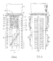
- the first three figures show the dowel in total.
- the dowel includes a dowel sleeve 1, for example, a length of at least 10 cm, preferably longer.
- the dowel sleeve 1 contains a tapered region 2, which ends in a top 3.
- a collar 4 is formed, and above the collar 4 a lug 5, which contains an impact protection.
- a plurality of triangular spreading elements 6 is arranged on the long side to be seen. These spreading elements 6 are in the FIG. 2 to see more clearly, because the FIG. 2 a side view of the anchor from one opposite FIG. 1 represented by 90 ° offset direction.
- a rib 7 can be seen, which passes over the entire length of the dowel sleeve to the tapered portion 2.
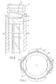
- FIG. 3 The longitudinal section of the FIG. 3 shows how the Aufsp Sonetti 6 look from the inside. It can at least be seen that the inside of the spreading elements 6 is smooth. Top in FIG. 3 it can be seen that in the approach 5 a thread 8 is formed, which forms the aforementioned impact protection.
- FIGS. 1 to 3 show, as already mentioned, the dowel in general view and should give an overview of the dowel in total.
- the following figures show details on a larger scale.
- FIG. 4 which shows the dowel from the same direction as the FIG. 1 .
- the lug 5 is formed, through which a screw is inserted into the dowel.
- the approach 5 is slightly conical and widens to the free end of the dowel.
- the projection 5 is arranged in the assembled state within the frame or the bore of the frame.
- the collar 4 which has a plurality of interrupted by 9 cuts segments.
- the actual dowel sleeve 1 which is cylindrical.
- the dowel sleeve has two extending in the longitudinal direction ribs 7, each forming a smooth continuous edge 10.
- the ribs 7 protrude beyond the outer surface of the dowel sleeve 1. They form an anti-twist device.
- each spreading element 6 has the shape of a triangle, which is connected in one piece with one of its sides 12 with the dowel sleeve 1. This side runs in the longitudinal direction of the dowel sleeve.
- Each triangular spreading element 6 has a transverse edge 13 to the longitudinal direction, said edges 13 are directed alternately in the direction of the rear and the front end of the dowel sleeve.
- the embarksp Gillium 6 are separated on two sides by slots from each other and from the dowel sleeve.
- the calculated from the top of two first Aufsp Sandersetti 6 in FIG. 4 have on their visible outer side a plurality of axially extending ribs 15 which are separated by grooves. These ribs form an anti-twist device.
- the ends of the ribs 15 are formed obliquely.
- a thread 8 is formed, which cooperates with the thread of the screw, which widens the dowel.
- the diameter of the collar 4 is equal to the distance between the edges 10 of the two ribs 7.
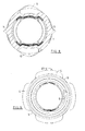
- FIG. 7 shows an end view of the dowel from the top 3 ago.
- the pairs of spreading elements 6 are arranged in rows which extend over an angular range of about 30 ° around the circumference. Centered between these rows of spreading elements 6, the ribs 7 of the rotation are formed.
- the four segments of the collar 4 are arranged at the same locations where the pairs of Aufspreizelementen 6 on the one hand and the ribs 7 on the other hand arranged are.
- FIG. 7 similar to the FIG. 5 that the spreading elements protrude radially beyond the outside of the dowel sleeve 1 in the not yet used state.
- FIG. 8 now shows a cross section through the dowel, which also shows that the ribs 7 protrude the rotation significantly over the other circumference of the dowel sleeve 1. Also, the projection of the Aufsp Schwarziana 6 can be seen here.
- FIG. 9 shows an end view of the dowel from the rear side, so from above into the FIGS. 1 to 6 ,
- the arrangement of the collar 4 can be seen, the outer edge of which extends approximately as far as the outer edge of the ribs 15 of the Aufsp Dahl implant that are barely visible.
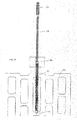
- the dowel serves to fasten a frame element, for example a window frame 19, to a masonry.
- the masonry is formed by a hollow brick 20.
- Such hollow blocks contain, as the name implies, cavities separated by webs.
- the dowel must be so long that it extends at least to a second bridge.
- the anchor is guided during insertion through the mutually aligned bores of the window frame 19 and the first web 21 into the bore in the second web 22.
- the screw 23 Only after the complete hammering of the anchor, limited by the collar 7, the screw 23 is screwed.
- the screw has a threaded shaft with a diameter corresponding to the diameter of the dowel, which then followed by a section 24 of enlarged diameter in the rear region.
- the diameter of this enlarged diameter portion 24 corresponds to the outer diameter of the anchor and thus the diameter of the wellbore in the window frame 19.
Landscapes
- Engineering & Computer Science (AREA)
- General Engineering & Computer Science (AREA)
- Mechanical Engineering (AREA)
- Dowels (AREA)
- Joining Of Building Structures In Genera (AREA)
- Piles And Underground Anchors (AREA)
Applications Claiming Priority (1)
| Application Number | Priority Date | Filing Date | Title |
|---|---|---|---|
| DE102011081742A DE102011081742A1 (de) | 2011-08-29 | 2011-08-29 | Dübel |
Publications (3)
| Publication Number | Publication Date |
|---|---|
| EP2565470A2 true EP2565470A2 (fr) | 2013-03-06 |
| EP2565470A3 EP2565470A3 (fr) | 2014-01-01 |
| EP2565470B1 EP2565470B1 (fr) | 2016-06-22 |
Family
ID=46690430
Family Applications (1)
| Application Number | Title | Priority Date | Filing Date |
|---|---|---|---|
| EP12181200.2A Active EP2565470B1 (fr) | 2011-08-29 | 2012-08-21 | Cheville |
Country Status (3)
| Country | Link |
|---|---|
| EP (1) | EP2565470B1 (fr) |
| DE (1) | DE102011081742A1 (fr) |
| ES (1) | ES2592176T3 (fr) |
Families Citing this family (2)
| Publication number | Priority date | Publication date | Assignee | Title |
|---|---|---|---|---|
| DE102020001583A1 (de) | 2020-03-11 | 2021-09-16 | TOX-Dübel-Technik GmbH | Spreizdübel |
| DE102024121863A1 (de) | 2024-07-31 | 2026-02-05 | Adolf Würth GmbH & Co. KG | Dübel mit weicherer Dübelhülse und härteren Spreizeinlagen |
Citations (2)
| Publication number | Priority date | Publication date | Assignee | Title |
|---|---|---|---|---|
| DE9110499U1 (de) | 1991-08-27 | 1991-10-31 | Ejot Adolf Böhl GmbH & Co KG, 5920 Bad Berleburg | Dübel |
| EP1855016A1 (fr) | 2006-05-10 | 2007-11-14 | Adolf Würth GmbH & Co. KG | Cheville |
Family Cites Families (9)
| Publication number | Priority date | Publication date | Assignee | Title |
|---|---|---|---|---|
| DE1500934A1 (de) * | 1966-03-12 | 1969-06-04 | Horst Spoerr | Haltekoerper oder Haltevorrichtungen,welche in eine Wand od.dgl. einsetzbar sind |
| CH480551A (de) * | 1968-08-15 | 1969-10-31 | Langensiepen Kg M | Spreizdübel |
| DE3238851A1 (de) * | 1982-10-20 | 1984-04-26 | Hilti Ag, Schaan | Spreizduebel |
| DE3317937A1 (de) * | 1982-11-10 | 1984-05-10 | Hilti Ag, Schaan | Huelsenfoermiger spreizduebel |
| DE3341211A1 (de) * | 1983-11-14 | 1985-05-30 | Hilti Ag, Schaan | Spreizduebel mit radial ausschwenkbaren spreizzungen |
| GB2289103A (en) * | 1994-04-29 | 1995-11-08 | Black & Decker Inc | Wall plugs having arms |
| DE10045650A1 (de) * | 2000-09-15 | 2002-03-28 | Adolf Wuerth Gmbh & Co Kg | Kunststoffdübel |
| DE10229577A1 (de) * | 2002-07-02 | 2004-01-15 | Fischerwerke Artur Fischer Gmbh & Co. Kg | Spreizdübel aus Kunststoff |
| FR2849121B1 (fr) * | 2002-12-18 | 2005-08-26 | Prospection & Inventions | Cheville a frapper |
-
2011
- 2011-08-29 DE DE102011081742A patent/DE102011081742A1/de not_active Withdrawn
-
2012
- 2012-08-21 EP EP12181200.2A patent/EP2565470B1/fr active Active
- 2012-08-21 ES ES12181200.2T patent/ES2592176T3/es active Active
Patent Citations (2)
| Publication number | Priority date | Publication date | Assignee | Title |
|---|---|---|---|---|
| DE9110499U1 (de) | 1991-08-27 | 1991-10-31 | Ejot Adolf Böhl GmbH & Co KG, 5920 Bad Berleburg | Dübel |
| EP1855016A1 (fr) | 2006-05-10 | 2007-11-14 | Adolf Würth GmbH & Co. KG | Cheville |
Also Published As
| Publication number | Publication date |
|---|---|
| DE102011081742A1 (de) | 2013-02-28 |
| EP2565470A3 (fr) | 2014-01-01 |
| ES2592176T3 (es) | 2016-11-28 |
| EP2565470B1 (fr) | 2016-06-22 |
Similar Documents
| Publication | Publication Date | Title |
|---|---|---|
| DE10035580B4 (de) | Formschlüssig setzbarer Hinterschneid-Anker | |
| EP2321542B1 (fr) | Agencement d'entraînement pour vis | |
| DE102010003014B4 (de) | Antriebsausbildung für einen Drehantrieb | |
| DE68901759T2 (de) | Duebel fuer eine hinterschnittene ankerbohrung. | |
| EP3374649B1 (fr) | Vis autotaraudeuse | |
| DE3715420A1 (de) | Distanzschraube | |
| DE202012013475U1 (de) | Profilverbindung | |
| WO2013120746A1 (fr) | Ancre de fixation et système de fixation comprenant une ancre de fixation | |
| EP0883755B1 (fr) | Cheville a percussion | |
| DE3148043A1 (de) | "duebel- und bolzenanordnung" | |
| EP2923092B1 (fr) | Cheville a expansion | |
| EP2565470B1 (fr) | Cheville | |
| DE3502607A1 (de) | Anker, insbesondere lastabhaengiger duebel | |
| DE102011111064A1 (de) | Anordnung zur, insbesondere distanzierten, Befestigung zumindest einer Dammstoffplatte an einem Gebäude | |
| CH479811A (de) | Spreizdübel | |
| EP2025952B1 (fr) | Piton à expansion | |
| EP0760429B1 (fr) | Cheville d'expansion en matière plastique | |
| EP0964169A2 (fr) | Cheville pour cadres | |
| DE19645081C1 (de) | Spreizdübel | |
| EP2634439B1 (fr) | Douille perforée pour une cheville | |
| EP1927766B1 (fr) | Douille perforée | |
| DE2832821A1 (de) | Spreizduebel | |
| DE102005034928A1 (de) | Klemmstift | |
| DE202023105457U1 (de) | Zum Einsetzen in ein Loch ausgelegter Adapter zur Anpassung des Lochs an ein dort zu fixierendes Befestigungsmittel | |
| EP3173633A1 (fr) | Cheville a expansion |
Legal Events
| Date | Code | Title | Description |
|---|---|---|---|
| PUAI | Public reference made under article 153(3) epc to a published international application that has entered the european phase |
Free format text: ORIGINAL CODE: 0009012 |
|
| AK | Designated contracting states |
Kind code of ref document: A2 Designated state(s): AL AT BE BG CH CY CZ DE DK EE ES FI FR GB GR HR HU IE IS IT LI LT LU LV MC MK MT NL NO PL PT RO RS SE SI SK SM TR |
|
| AX | Request for extension of the european patent |
Extension state: BA ME |
|
| PUAL | Search report despatched |
Free format text: ORIGINAL CODE: 0009013 |
|
| AK | Designated contracting states |
Kind code of ref document: A3 Designated state(s): AL AT BE BG CH CY CZ DE DK EE ES FI FR GB GR HR HU IE IS IT LI LT LU LV MC MK MT NL NO PL PT RO RS SE SI SK SM TR |
|
| AX | Request for extension of the european patent |
Extension state: BA ME |
|
| RIC1 | Information provided on ipc code assigned before grant |
Ipc: F16B 13/00 20060101AFI20131128BHEP Ipc: F16B 13/12 20060101ALI20131128BHEP |
|
| 17P | Request for examination filed |
Effective date: 20140129 |
|
| RBV | Designated contracting states (corrected) |
Designated state(s): AL AT BE BG CH CY CZ DE DK EE ES FI FR GB GR HR HU IE IS IT LI LT LU LV MC MK MT NL NO PL PT RO RS SE SI SK SM TR |
|
| GRAP | Despatch of communication of intention to grant a patent |
Free format text: ORIGINAL CODE: EPIDOSNIGR1 |
|
| INTG | Intention to grant announced |
Effective date: 20160209 |
|
| RAP1 | Party data changed (applicant data changed or rights of an application transferred) |
Owner name: WUERTH INTERNATIONAL AG Owner name: ADOLF WUERTH GMBH & CO. KG |
|
| GRAS | Grant fee paid |
Free format text: ORIGINAL CODE: EPIDOSNIGR3 |
|
| GRAA | (expected) grant |
Free format text: ORIGINAL CODE: 0009210 |
|
| AK | Designated contracting states |
Kind code of ref document: B1 Designated state(s): AL AT BE BG CH CY CZ DE DK EE ES FI FR GB GR HR HU IE IS IT LI LT LU LV MC MK MT NL NO PL PT RO RS SE SI SK SM TR |
|
| REG | Reference to a national code |
Ref country code: GB Ref legal event code: FG4D Free format text: NOT ENGLISH |
|
| REG | Reference to a national code |
Ref country code: CH Ref legal event code: EP |
|
| REG | Reference to a national code |
Ref country code: IE Ref legal event code: FG4D Free format text: LANGUAGE OF EP DOCUMENT: GERMAN |
|
| REG | Reference to a national code |
Ref country code: AT Ref legal event code: REF Ref document number: 807838 Country of ref document: AT Kind code of ref document: T Effective date: 20160715 |
|
| REG | Reference to a national code |
Ref country code: DE Ref legal event code: R096 Ref document number: 502012007439 Country of ref document: DE |
|
| REG | Reference to a national code |
Ref country code: FR Ref legal event code: PLFP Year of fee payment: 5 |
|
| REG | Reference to a national code |
Ref country code: LT Ref legal event code: MG4D |
|
| REG | Reference to a national code |
Ref country code: NL Ref legal event code: MP Effective date: 20160622 |
|
| PG25 | Lapsed in a contracting state [announced via postgrant information from national office to epo] |
Ref country code: LT Free format text: LAPSE BECAUSE OF FAILURE TO SUBMIT A TRANSLATION OF THE DESCRIPTION OR TO PAY THE FEE WITHIN THE PRESCRIBED TIME-LIMIT Effective date: 20160622 Ref country code: FI Free format text: LAPSE BECAUSE OF FAILURE TO SUBMIT A TRANSLATION OF THE DESCRIPTION OR TO PAY THE FEE WITHIN THE PRESCRIBED TIME-LIMIT Effective date: 20160622 Ref country code: NO Free format text: LAPSE BECAUSE OF FAILURE TO SUBMIT A TRANSLATION OF THE DESCRIPTION OR TO PAY THE FEE WITHIN THE PRESCRIBED TIME-LIMIT Effective date: 20160922 |
|
| REG | Reference to a national code |
Ref country code: ES Ref legal event code: FG2A Ref document number: 2592176 Country of ref document: ES Kind code of ref document: T3 Effective date: 20161128 |
|
| PG25 | Lapsed in a contracting state [announced via postgrant information from national office to epo] |
Ref country code: LV Free format text: LAPSE BECAUSE OF FAILURE TO SUBMIT A TRANSLATION OF THE DESCRIPTION OR TO PAY THE FEE WITHIN THE PRESCRIBED TIME-LIMIT Effective date: 20160622 Ref country code: GR Free format text: LAPSE BECAUSE OF FAILURE TO SUBMIT A TRANSLATION OF THE DESCRIPTION OR TO PAY THE FEE WITHIN THE PRESCRIBED TIME-LIMIT Effective date: 20160923 Ref country code: RS Free format text: LAPSE BECAUSE OF FAILURE TO SUBMIT A TRANSLATION OF THE DESCRIPTION OR TO PAY THE FEE WITHIN THE PRESCRIBED TIME-LIMIT Effective date: 20160622 Ref country code: NL Free format text: LAPSE BECAUSE OF FAILURE TO SUBMIT A TRANSLATION OF THE DESCRIPTION OR TO PAY THE FEE WITHIN THE PRESCRIBED TIME-LIMIT Effective date: 20160622 Ref country code: SE Free format text: LAPSE BECAUSE OF FAILURE TO SUBMIT A TRANSLATION OF THE DESCRIPTION OR TO PAY THE FEE WITHIN THE PRESCRIBED TIME-LIMIT Effective date: 20160622 Ref country code: HR Free format text: LAPSE BECAUSE OF FAILURE TO SUBMIT A TRANSLATION OF THE DESCRIPTION OR TO PAY THE FEE WITHIN THE PRESCRIBED TIME-LIMIT Effective date: 20160622 |
|
| PG25 | Lapsed in a contracting state [announced via postgrant information from national office to epo] |
Ref country code: BE Free format text: LAPSE BECAUSE OF NON-PAYMENT OF DUE FEES Effective date: 20160831 |
|
| PG25 | Lapsed in a contracting state [announced via postgrant information from national office to epo] |
Ref country code: RO Free format text: LAPSE BECAUSE OF FAILURE TO SUBMIT A TRANSLATION OF THE DESCRIPTION OR TO PAY THE FEE WITHIN THE PRESCRIBED TIME-LIMIT Effective date: 20160622 Ref country code: CZ Free format text: LAPSE BECAUSE OF FAILURE TO SUBMIT A TRANSLATION OF THE DESCRIPTION OR TO PAY THE FEE WITHIN THE PRESCRIBED TIME-LIMIT Effective date: 20160622 Ref country code: IS Free format text: LAPSE BECAUSE OF FAILURE TO SUBMIT A TRANSLATION OF THE DESCRIPTION OR TO PAY THE FEE WITHIN THE PRESCRIBED TIME-LIMIT Effective date: 20161022 Ref country code: EE Free format text: LAPSE BECAUSE OF FAILURE TO SUBMIT A TRANSLATION OF THE DESCRIPTION OR TO PAY THE FEE WITHIN THE PRESCRIBED TIME-LIMIT Effective date: 20160622 Ref country code: SK Free format text: LAPSE BECAUSE OF FAILURE TO SUBMIT A TRANSLATION OF THE DESCRIPTION OR TO PAY THE FEE WITHIN THE PRESCRIBED TIME-LIMIT Effective date: 20160622 |
|
| PG25 | Lapsed in a contracting state [announced via postgrant information from national office to epo] |
Ref country code: PT Free format text: LAPSE BECAUSE OF FAILURE TO SUBMIT A TRANSLATION OF THE DESCRIPTION OR TO PAY THE FEE WITHIN THE PRESCRIBED TIME-LIMIT Effective date: 20161024 Ref country code: SM Free format text: LAPSE BECAUSE OF FAILURE TO SUBMIT A TRANSLATION OF THE DESCRIPTION OR TO PAY THE FEE WITHIN THE PRESCRIBED TIME-LIMIT Effective date: 20160622 Ref country code: PL Free format text: LAPSE BECAUSE OF FAILURE TO SUBMIT A TRANSLATION OF THE DESCRIPTION OR TO PAY THE FEE WITHIN THE PRESCRIBED TIME-LIMIT Effective date: 20160622 |
|
| REG | Reference to a national code |
Ref country code: DE Ref legal event code: R097 Ref document number: 502012007439 Country of ref document: DE |
|
| PG25 | Lapsed in a contracting state [announced via postgrant information from national office to epo] |
Ref country code: MC Free format text: LAPSE BECAUSE OF FAILURE TO SUBMIT A TRANSLATION OF THE DESCRIPTION OR TO PAY THE FEE WITHIN THE PRESCRIBED TIME-LIMIT Effective date: 20160622 |
|
| PLBE | No opposition filed within time limit |
Free format text: ORIGINAL CODE: 0009261 |
|
| STAA | Information on the status of an ep patent application or granted ep patent |
Free format text: STATUS: NO OPPOSITION FILED WITHIN TIME LIMIT |
|
| GBPC | Gb: european patent ceased through non-payment of renewal fee |
Effective date: 20160922 |
|
| 26N | No opposition filed |
Effective date: 20170323 |
|
| PG25 | Lapsed in a contracting state [announced via postgrant information from national office to epo] |
Ref country code: DK Free format text: LAPSE BECAUSE OF FAILURE TO SUBMIT A TRANSLATION OF THE DESCRIPTION OR TO PAY THE FEE WITHIN THE PRESCRIBED TIME-LIMIT Effective date: 20160622 |
|
| REG | Reference to a national code |
Ref country code: IE Ref legal event code: MM4A |
|
| PG25 | Lapsed in a contracting state [announced via postgrant information from national office to epo] |
Ref country code: IE Free format text: LAPSE BECAUSE OF NON-PAYMENT OF DUE FEES Effective date: 20160821 Ref country code: GB Free format text: LAPSE BECAUSE OF NON-PAYMENT OF DUE FEES Effective date: 20160922 |
|
| REG | Reference to a national code |
Ref country code: FR Ref legal event code: PLFP Year of fee payment: 6 |
|
| PG25 | Lapsed in a contracting state [announced via postgrant information from national office to epo] |
Ref country code: LU Free format text: LAPSE BECAUSE OF NON-PAYMENT OF DUE FEES Effective date: 20160821 Ref country code: SI Free format text: LAPSE BECAUSE OF FAILURE TO SUBMIT A TRANSLATION OF THE DESCRIPTION OR TO PAY THE FEE WITHIN THE PRESCRIBED TIME-LIMIT Effective date: 20160622 |
|
| PG25 | Lapsed in a contracting state [announced via postgrant information from national office to epo] |
Ref country code: HU Free format text: LAPSE BECAUSE OF FAILURE TO SUBMIT A TRANSLATION OF THE DESCRIPTION OR TO PAY THE FEE WITHIN THE PRESCRIBED TIME-LIMIT; INVALID AB INITIO Effective date: 20120821 Ref country code: CY Free format text: LAPSE BECAUSE OF FAILURE TO SUBMIT A TRANSLATION OF THE DESCRIPTION OR TO PAY THE FEE WITHIN THE PRESCRIBED TIME-LIMIT Effective date: 20160622 |
|
| PG25 | Lapsed in a contracting state [announced via postgrant information from national office to epo] |
Ref country code: TR Free format text: LAPSE BECAUSE OF FAILURE TO SUBMIT A TRANSLATION OF THE DESCRIPTION OR TO PAY THE FEE WITHIN THE PRESCRIBED TIME-LIMIT Effective date: 20160622 Ref country code: MK Free format text: LAPSE BECAUSE OF FAILURE TO SUBMIT A TRANSLATION OF THE DESCRIPTION OR TO PAY THE FEE WITHIN THE PRESCRIBED TIME-LIMIT Effective date: 20160622 Ref country code: MT Free format text: LAPSE BECAUSE OF FAILURE TO SUBMIT A TRANSLATION OF THE DESCRIPTION OR TO PAY THE FEE WITHIN THE PRESCRIBED TIME-LIMIT Effective date: 20160622 |
|
| PG25 | Lapsed in a contracting state [announced via postgrant information from national office to epo] |
Ref country code: BG Free format text: LAPSE BECAUSE OF FAILURE TO SUBMIT A TRANSLATION OF THE DESCRIPTION OR TO PAY THE FEE WITHIN THE PRESCRIBED TIME-LIMIT Effective date: 20160622 |
|
| REG | Reference to a national code |
Ref country code: FR Ref legal event code: PLFP Year of fee payment: 7 |
|
| PG25 | Lapsed in a contracting state [announced via postgrant information from national office to epo] |
Ref country code: AL Free format text: LAPSE BECAUSE OF FAILURE TO SUBMIT A TRANSLATION OF THE DESCRIPTION OR TO PAY THE FEE WITHIN THE PRESCRIBED TIME-LIMIT Effective date: 20160622 |
|
| P01 | Opt-out of the competence of the unified patent court (upc) registered |
Effective date: 20230609 |
|
| PGFP | Annual fee paid to national office [announced via postgrant information from national office to epo] |
Ref country code: ES Payment date: 20250925 Year of fee payment: 14 |
|
| PGFP | Annual fee paid to national office [announced via postgrant information from national office to epo] |
Ref country code: DE Payment date: 20250820 Year of fee payment: 14 |
|
| PGFP | Annual fee paid to national office [announced via postgrant information from national office to epo] |
Ref country code: IT Payment date: 20250825 Year of fee payment: 14 |
|
| PGFP | Annual fee paid to national office [announced via postgrant information from national office to epo] |
Ref country code: FR Payment date: 20250829 Year of fee payment: 14 Ref country code: AT Payment date: 20250821 Year of fee payment: 14 |
|
| PGFP | Annual fee paid to national office [announced via postgrant information from national office to epo] |
Ref country code: CH Payment date: 20250901 Year of fee payment: 14 |