EP2565510A2 - Dispositif de raccord de tuyaux à double paroi - Google Patents
Dispositif de raccord de tuyaux à double paroi Download PDFInfo
- Publication number
- EP2565510A2 EP2565510A2 EP12178009A EP12178009A EP2565510A2 EP 2565510 A2 EP2565510 A2 EP 2565510A2 EP 12178009 A EP12178009 A EP 12178009A EP 12178009 A EP12178009 A EP 12178009A EP 2565510 A2 EP2565510 A2 EP 2565510A2
- Authority
- EP
- European Patent Office
- Prior art keywords
- pipe coupling
- ring
- coupling parts
- pipe
- coupling part
- Prior art date
- Legal status (The legal status is an assumption and is not a legal conclusion. Google has not performed a legal analysis and makes no representation as to the accuracy of the status listed.)
- Granted
Links
Images


Classifications
-
- F—MECHANICAL ENGINEERING; LIGHTING; HEATING; WEAPONS; BLASTING
- F16—ENGINEERING ELEMENTS AND UNITS; GENERAL MEASURES FOR PRODUCING AND MAINTAINING EFFECTIVE FUNCTIONING OF MACHINES OR INSTALLATIONS; THERMAL INSULATION IN GENERAL
- F16L—PIPES; JOINTS OR FITTINGS FOR PIPES; SUPPORTS FOR PIPES, CABLES OR PROTECTIVE TUBING; MEANS FOR THERMAL INSULATION IN GENERAL
- F16L39/00—Joints or fittings for double-walled or multi-channel pipes or pipe assemblies
- F16L39/005—Joints or fittings for double-walled or multi-channel pipes or pipe assemblies for concentric pipes
-
- F—MECHANICAL ENGINEERING; LIGHTING; HEATING; WEAPONS; BLASTING
- F16—ENGINEERING ELEMENTS AND UNITS; GENERAL MEASURES FOR PRODUCING AND MAINTAINING EFFECTIVE FUNCTIONING OF MACHINES OR INSTALLATIONS; THERMAL INSULATION IN GENERAL
- F16L—PIPES; JOINTS OR FITTINGS FOR PIPES; SUPPORTS FOR PIPES, CABLES OR PROTECTIVE TUBING; MEANS FOR THERMAL INSULATION IN GENERAL
- F16L3/00—Supports for pipes, cables or protective tubing, e.g. hangers, holders, clamps, cleats, clips, brackets
- F16L3/08—Supports for pipes, cables or protective tubing, e.g. hangers, holders, clamps, cleats, clips, brackets substantially surrounding the pipe, cable or protective tubing
- F16L3/12—Supports for pipes, cables or protective tubing, e.g. hangers, holders, clamps, cleats, clips, brackets substantially surrounding the pipe, cable or protective tubing comprising a member substantially surrounding the pipe, cable or protective tubing
- F16L3/1222—Supports for pipes, cables or protective tubing, e.g. hangers, holders, clamps, cleats, clips, brackets substantially surrounding the pipe, cable or protective tubing comprising a member substantially surrounding the pipe, cable or protective tubing the member having the form of a closed ring, e.g. used for the function of two adjacent pipe sections
-
- F—MECHANICAL ENGINEERING; LIGHTING; HEATING; WEAPONS; BLASTING
- F16—ENGINEERING ELEMENTS AND UNITS; GENERAL MEASURES FOR PRODUCING AND MAINTAINING EFFECTIVE FUNCTIONING OF MACHINES OR INSTALLATIONS; THERMAL INSULATION IN GENERAL
- F16L—PIPES; JOINTS OR FITTINGS FOR PIPES; SUPPORTS FOR PIPES, CABLES OR PROTECTIVE TUBING; MEANS FOR THERMAL INSULATION IN GENERAL
- F16L37/00—Couplings of the quick-acting type
- F16L37/56—Couplings of the quick-acting type for double-walled or multi-channel pipes or pipe assemblies
- F16L37/565—Concentric pipes
-
- Y—GENERAL TAGGING OF NEW TECHNOLOGICAL DEVELOPMENTS; GENERAL TAGGING OF CROSS-SECTIONAL TECHNOLOGIES SPANNING OVER SEVERAL SECTIONS OF THE IPC; TECHNICAL SUBJECTS COVERED BY FORMER USPC CROSS-REFERENCE ART COLLECTIONS [XRACs] AND DIGESTS
- Y10—TECHNICAL SUBJECTS COVERED BY FORMER USPC
- Y10T—TECHNICAL SUBJECTS COVERED BY FORMER US CLASSIFICATION
- Y10T29/00—Metal working
- Y10T29/49—Method of mechanical manufacture
- Y10T29/49826—Assembling or joining
- Y10T29/49947—Assembling or joining by applying separate fastener
- Y10T29/49966—Assembling or joining by applying separate fastener with supplemental joining
- Y10T29/49968—Metal fusion joining
Definitions
- the present invention relates to a device for connecting jacketed pipes, with two mutually corresponding pipe coupling parts and a securing element for axially connecting the pipe coupling parts, wherein the pipe coupling parts each having an inner tube to be welded to an inner ring to be welded to a casing tube outer ring and between the inner ring and the Outer ring each having a broken by a plurality of webs passage. Furthermore, the present invention relates to a method for connecting double-walled tubes by means of such a device.
- Pipe couplings Devices for connecting pipes, which are also referred to as pipe couplings, are known in many designs. Especially popular are pipe couplings, with which two pipe ends can be easily connected and disconnected without additional tools. Depending on the field of application of the piping, there are manifold requirements for the pipe couplings to be used.
- Powerful pipe couplings should allow the connected pipes in the installed state relative to each other to twist or pivot, without the flow or the function of the coupling is impaired.
- pipe couplings should also be able to be used with lines that are subjected to high pressures.
- the invention is therefore the object of the above-mentioned and previously explained in detail double pipe coupling to design and further that the known from the prior art disadvantages are avoided, that its cost-effective production and a simple assembly of the coupling is possible and that a balance of Manufacturing tolerances of the individual tubes is made possible.
- a device for connecting jacketed pipes of the type mentioned above in that at least one of the pipe coupling parts is formed divided and has two separate components, namely an inner member which is formed by the inner ring or at least this comprises and has an external thread , and an outer member which is formed by or comprises the outer ring and an inner thread corresponding to the outer thread of the inner member has, so that the outer member can be screwed onto the inner member.
- the inventive design of the pipe coupling part with two separate, screwed together components brings various advantages. This makes assembly easy. In this first, the inner ring, the split formed coupling part is welded to the associated inner tube.
- the outer component is screwed onto the inner component so far that its outer ring comes into contact with the associated jacket tube.
- the outer ring is welded to the jacket tube.
- the outer member is screwed with the outer ring on the inner member, the outer ring can always be brought to the casing pipe in abutment.
- the external thread and the internal thread are designed and positioned such that the outer component can be screwed onto the inner component so far that the outer component comes into abutment against a jacket tube to be welded when the inner component is welded to an inner tube.
- the external thread of the inner member may be longer than the corresponding internal thread of the outer member.
- a relative rotation of the pipe ends to be joined is achieved according to a further embodiment of the invention by the two pipe coupling parts are rotatably connected to each other.
- Such configured double pipe coupling allows even after closing by the securing element, that can be easily rotated about its axis welded to the one pipe coupling part piece of pipe against the adjacent and welded to the opposite pipe coupling piece pipe section. This is in some cases, e.g. for aligning a valve or when twisting pipe sections required.
- the relative movement between the fixed flanges can be achieved in particular by the use of lubricants and / or by the use of sliding or rolling bearings.
- the inner rings of the two coupling parts are pushed into one another, wherein a clearance in the axial direction is provided between the two inner rings.
- the outer rings of the two pipe coupling parts can be pushed into one another, wherein a clearance in the axial direction is provided between the two outer rings.
- the thus pre-assembled pipe coupling is positioned between the double-jacket pipes to be joined together, and the inner rings are welded to the associated inner pipes.
- the inner rings can be brought to the associated inner tubes securely in abutment, since the two pipe coupling parts are mutually displaceable.
- the associated jacket tube is brought into abutment on the outer ring of the one-piece pipe coupling part, and the two components are welded together.
- the outer component of the split-formed pipe coupling part is screwed onto the inner component so far that the outer component comes into abutment with the associated jacket pipe and the outer component can be welded to the jacket pipe.
- a further embodiment of the invention is between the inner ring of a pipe coupling part and the outer ring of the other pipe coupling part at least one ring seal - in particular in the radial direction - arranged.
- the ring seals are provided in such areas in which sufficient sealing surfaces of the corresponding pipe coupling parts are present.
- the use of a ring seal has the advantage that an excellent sealing effect can be achieved even with a relative movement between the surfaces to be sealed.
- the ring seal may be an O-ring or a radial shaft seal.
- a further embodiment of the invention provides that the two components of the pipe coupling part are rotatably connected to each other by means of at least one securing element. Due to the non-rotatable connection torsional stresses acting on the pipe coupling parts can be safely absorbed.
- a securing element is preferably a cylinder pin mounted in the axial direction, since this construction can be realized effectively and in a particularly space-saving manner.
- the securing element which axially fixes the pipe coupling parts
- a clamp is often by hand by one with a Press spring-connected clamping lever and is characterized by an easy and quick assembly and disassembly without the use of additional tools (so-called quick coupling). As a result, savings can also be realized in personnel costs.
- connection with a combination collar has the advantage that it can be transported in the closed state on the outer ring of the pipe coupling part of the sleeve piece of the pipe coupling. Furthermore, such a combination cell can also be connected to a suspension eye, since corresponding pipelines, which are often used in underground use, are usually suspended from the track construction in order to avoid deformations.
- the securing element is a union nut. Even when using a union nut no additional (impact) tools are required. Thus, the connection by hand screw together and solve. A retightening is not required after screwing the nut regularly. Often, the threaded piece and the union nut conical threads with cylindrical outlet.
- an unencapsulated thread can be used or an encapsulation by means of appropriately arranged, additional seals. The encapsulation forms a reliable protection against contamination, so that the connection can be easily solved even after long operation.
- a split pin can be provided which prevents unintentional unscrewing and increases the reliability of the double pipe coupling.
- the securing element which fixes the pipe coupling parts axially, is designed as a ball chain.
- a ball chain for axial securing a particularly low friction between the fixed flanges can be achieved, making it easy to rotate relative to each other.
- a coupling with ball chain is out of the DE 33 24 271 A1 known.
- a double nipple is arranged, which has an inner ring and a non-rotatably connected to the inner ring outer ring.
- the use of a double nipple makes it possible to design the two pipe coupling parts identically. This has the advantage that only one mold must be used, especially in casting production of pipe coupling parts, such as cast steel. In this way, the production of the pipe coupling parts can be made more economical.
- the double-pipe coupling can have a double nipple in any type of backup, especially in axial securing by a clamp, union nut or ball chain.
- the high-pressure supply line there is an operating pressure of about 40 MPa, while the return line is operated at about 4-7 MPa.
- the wall thickness of the inner high-pressure line can be selected independently of the wall thickness of the outer low-pressure or return line. For the proposed application, this may mean that the wall thickness of the inner tubes is greater than the wall thickness of the jacket tubes.
- the underground use of a double-walled tube has the advantage that in case of leakage of - due to the higher pressure - more stressed inner tube, the outer jacket tube prevents immediate leakage of fluid from the double-jacket tube. This reduces the risk of injury and, in particular in mining, can thus avoid unnecessary repairs in hard-to-reach areas.
- spacers are mounted between the inner tubes and the jacket tubes at predetermined intervals, which - comparable to the fixed flanges - radially spaced both tubes.
- the transitions between the webs of a pipe coupling part or both pipe coupling parts are rounded in their transition region to the associated inner ring and / or outer ring.
- the webs can be rounded at their end face pointing to the coupling outer side both in the transition region to the outer ring and in the transition region to the inner ring and in particular form an approximately part-circular curvature.
- the webs of the one-piece pipe coupling part can be rounded only at their transition to the inner ring.
- the webs may be rounded at its facing the clutch inner side end face and / or on its side facing the clutch outer face in the transition region to the outer ring. A rounding to the inner ring is out of the question, since the screwing between the inner and the outer component takes place here.
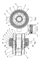
- Fig. 1 shows a device for connecting double-jacket pipes, which is also referred to below as a double-pipe coupling.
- the illustrated double-pipe coupling essentially has two pipe coupling parts 1, 2 and a securing element for the axial connection of the pipe coupling parts 1, 2.
- the pipe coupling parts 1, 2 each have an inner ring 1i and 2i and an outer ring 1a and 2a, wherein each of the inner rings 1i and 2i has a weld-on end 3 and 4 respectively and each of the outer rings 1a and 2a has a weld-on end 3 and 4, respectively.
- About the Ansch healthenden 3, 4, 5, 6, the pipe coupling parts 1, 2 to the ends of each of an inner tube 7, 8 and a jacket tube 9, 10 are welded.
- the inner tubes 7, 8 and the jacket tubes 9, 10 are arranged substantially collinear, so that between the inner tube 7 and the jacket tube 9 and between the inner tube 8 and the jacket tube 10 in each case an unspecified annular space is formed.
- FIG. 1 right-hand pipe coupling part 2 of two separate components, namely an inner component, which is essentially formed by the inner ring 1i of the pipe coupling part 1, and an outer member which is formed by the outer ring 1a with the webs 11 and the passages 12.
- the outer component is screwed onto the inner component.
- the inner ring 1i has an external thread 13 and the outer component has a corresponding internal thread 14.
- the external thread 13 is formed longer than the corresponding internal thread 14.
- the two pipe coupling parts 1, 2 are connected together in a conventional manner by a clamp 16 which is placed around the pipe coupling parts 1, 2 and the radial protruding paragraphs of the pipe coupling parts 1, 2 surrounds to fix the pipe coupling parts 1, 2 axially to each other.
- the inner rings 1i, 2i of the two pipe coupling parts 1, 2 are pushed into one another, wherein between the two inner rings 1i, 2i a game S is provided in the axial direction.
- the outer rings 1a, 2a of the two pipe coupling parts 1, 2 are pushed into one another, wherein between the two outer rings 1a, 2a a game in the axial direction remains.
- the annular gaps between the inner rings 1i, 2i and the outer rings 1a, 2a are sealed by corresponding annular seals 15.
- the two pipe coupling parts 1, 2 are put together. Subsequently, the two inner rings 1i, 2i are welded in the region of their welding ends 3, 4 to the associated inner tubes 7, 8.
- the inner rings 1i, 2i can be positioned exactly on the inner tubes 7, 8, since the two tube coupling parts 1, 2 are axially displaceable relative to one another. Subsequently, the left in the drawing casing 10 is brought to the stop on the one-piece pipe coupling part 2. Now, the outer member with the outer ring 1a of the two-part pipe coupling part 1 relative to the inner ring 1i so far twisted until it comes to the right in the drawing casing 9 in abutment. Finally, the welds between the jacket tubes 9, 10 and the welds 5, 6 of the outer rings 1a, 2a are produced.
- FIGS. 3 and 4 show a similar construction of a double pipe coupling, wherein instead of the clamp 16 a combination collar 36 is used.
- the use of a combination bowl has the advantage that it is held in a form-fitting manner during transport on the outer ring 22a and indeed in a circumferential groove 37.
- the combination cell 36 has two clamp halves 36A and 36B, which is folded around in a fixed position around the outer ring 22a (and 21a).
- Out Fig. 4 shows that in the upper part of the clamp half 36A a suspension lug 38 is arranged in order to suspend the pipe provided with the double pipe coupling according to the invention, for example when used in underground mining.
- FIGS. 5 and 6 and FIGS. 7 and 8 show two alternatives of a double-pipe coupling, in which the two outer rings 41a, 42a and 41a ', 42a' are each fixed by a union nut 56 or 56 'with threads 57 and 57' in the axial direction.
- the assembly and disassembly of the invention and in the FIGS. 5 and 6 shown double pipe coupling allows a connection by hand, since the thread 57 of the cap nut 56 is formed conically with a cylindrical structure.
- the use of a union nut 56 'with a cylindrical thread 57' requires for assembly / disassembly, however, always a striking tool.
- the illustrated union nuts 56, 56 ' have radially projecting webs 58 and 58', but it is also possible, although not shown, that the union nuts can also be provided with corresponding radial blind holes to be closed or opened by means of a corresponding tool to become. In this case, however, the pipe coupling thus equipped builds significantly smaller than with the projecting webs 58 and 58 '.
- the inner ring 41i 'and the associated outer ring 41a' of the pipe coupling part 41 ' can be rotatably connected together in the desired position, for example by the use of a cylinder pin 49 shown in the axial direction shown in the axial direction.
- a non-rotatable connection is in particular then required if additional torsional moments are introduced into the screw, as for example in the embodiment according to the FIGS. 7 and 8 the case is.
- the embodiment with the cylindrical pin 49 is particularly well from the detailed representation according to Fig. 7A out.
- a single ball chain 76 is provided as an axial securing element.
- a common circumferential groove 77 is incorporated, in which the ball chain 76 is inserted to prevent axial displacement of the two pipe coupling parts 61 and 62.
- the insertion and withdrawal of the ball chain 76 is particularly simple if a two-piece ball chain 76, so a ball chain 76 is used with two loose ends. This is introduced through an opening 78 in the groove 77, wherein an assembly aid 79 in the region of the recess 78 ensures the proper position.
- the chain links of the ball chain 76 may be balls, rollers, discs, cylinders or the like.
- the recess 78 can be covered with a protective clip 80, which is particularly clear Fig. 10 can be seen. It is not shown that the circumferential groove 77 can also be acted upon by means of a correspondingly arranged lubricating nipple with lubricant, in particular lubricating grease, in order to simplify the subsequent removal of the ball chain 76 from the double-tube coupling.
- FIG. 11 another embodiment of a double pipe coupling according to the invention shown.
- This essentially corresponds to the one in FIG. 5 illustrated embodiment.
- the difference is only in the configuration of the webs 51, 51 a of the pipe coupling parts 41, 42.
- the webs 51 a of the integrally formed pipe coupling part 42 at its coupling to the outside, ie to the left-facing side in the transition to the outer ring 42 a and the inner ring 42 i to form a part-circular curvature W formed rounded.
- the webs 51a are rounded off at their side facing the clutch inner side right side in their transition to the inner ring 42i. Because the Webs complete 51a on its inwardly facing side flush with the outer ring 42a, here the transition is rectilinear.
- the webs 51 of the two-part right pipe coupling part 41 are rounded at its inwardly facing end face and at its outwardly facing end face in the transition to the outer ring 41 a. Since the outer component of the two-part pipe coupling part 41 is screwed onto the inner ring 41i with the outer ring 41a and the webs 51, rounded transitions are not possible here.
Landscapes
- Engineering & Computer Science (AREA)
- General Engineering & Computer Science (AREA)
- Mechanical Engineering (AREA)
- Quick-Acting Or Multi-Walled Pipe Joints (AREA)
- Mutual Connection Of Rods And Tubes (AREA)
Applications Claiming Priority (2)
| Application Number | Priority Date | Filing Date | Title |
|---|---|---|---|
| DE201110111524 DE102011111524A1 (de) | 2011-08-31 | 2011-08-31 | Vorrichtung zum Verbinden von Doppelmantelrohren |
| DE201220101837 DE202012101837U1 (de) | 2011-08-31 | 2012-05-18 | Vorrichtung zum Verbinden von Doppelmantelrohren (zweiteiliges Rohrkupplungsteil) |
Related Parent Applications (1)
| Application Number | Title | Priority Date | Filing Date |
|---|---|---|---|
| DE202012101837U Previously-Filed-Application | 2012-05-18 |
Publications (3)
| Publication Number | Publication Date |
|---|---|
| EP2565510A2 true EP2565510A2 (fr) | 2013-03-06 |
| EP2565510A3 EP2565510A3 (fr) | 2014-06-04 |
| EP2565510B1 EP2565510B1 (fr) | 2015-01-21 |
Family
ID=47502604
Family Applications (1)
| Application Number | Title | Priority Date | Filing Date |
|---|---|---|---|
| EP20120178009 Active EP2565510B1 (fr) | 2011-08-31 | 2012-07-26 | Dispositif de raccord de tuyaux à double paroi |
Country Status (4)
| Country | Link |
|---|---|
| US (1) | US8991871B2 (fr) |
| EP (1) | EP2565510B1 (fr) |
| DE (2) | DE102011111524A1 (fr) |
| RU (1) | RU2508492C1 (fr) |
Cited By (1)
| Publication number | Priority date | Publication date | Assignee | Title |
|---|---|---|---|---|
| EP2851600A1 (fr) * | 2013-09-20 | 2015-03-25 | Siemens Aktiengesellschaft | Agencement de liaison de tube, système de conduites de fluide haute pression d'un moteur à combustion interne dualfuel, moteur à combustion interne dualfuel et utilisation d'un écrou de serrage |
Families Citing this family (15)
| Publication number | Priority date | Publication date | Assignee | Title |
|---|---|---|---|---|
| WO2013052741A2 (fr) * | 2011-10-07 | 2013-04-11 | Eaton Corporation | Adaptateur et raccord de tube à double paroi |
| RU2645378C2 (ru) * | 2016-03-18 | 2018-02-21 | Публичное акционерное общество "Транснефть" (ПАО "Транснефть") | Устройство и способ соединения труб защитного кожуха и размещаемого в нем рабочего трубопровода |
| RU2662071C1 (ru) * | 2016-06-27 | 2018-07-25 | Публичное акционерное общество "Транснефть" (ПАО "Транснефть") | Способ замены труб защитного кожуха и размещенного в нем рабочего трубопровода и устройство для его осуществления |
| US10359142B2 (en) * | 2016-06-27 | 2019-07-23 | The Boeing Company | Dual duct flexible coupling apparatus and methods of use |
| TWI644049B (zh) * | 2017-03-23 | 2018-12-11 | 億鴻興科技有限公司 | Chemical device delivery line coupling device |
| US10571062B2 (en) | 2017-06-23 | 2020-02-25 | United Technologies Corporation | Middle threaded fitting |
| DK180026B1 (en) | 2018-03-12 | 2020-01-24 | Mbh-International A/S | A flexible double lumen tube and a tube coupling system for same |
| EP3862611A1 (fr) * | 2020-02-07 | 2021-08-11 | Winterthur Gas & Diesel AG | Raccord à bride permettant de raccorder deux pièces de conduite à double paroi, système d'alimentation en gaz et gros moteur |
| US11732831B2 (en) * | 2021-02-05 | 2023-08-22 | Honeywell International Inc. | Fluid flow connector |
| EP4372164B1 (fr) | 2021-06-30 | 2026-02-04 | Consat AB | Appareil de récupération de chaleur des eaux grises |
| US20250361020A1 (en) * | 2022-06-14 | 2025-11-27 | Airbus Operations Limited | An aircraft assembly |
| CN119278318A (zh) | 2022-07-15 | 2025-01-07 | 韦尔泵阀解决方案有限公司 | 夹套管泵 |
| CN115282471B (zh) * | 2022-08-16 | 2025-08-26 | 深圳核心医疗科技股份有限公司 | 壳体组件及其制造方法和血泵 |
| US12215551B2 (en) * | 2022-09-13 | 2025-02-04 | Brocato Construction Company Inc. | Auger boring using a pipe seal assembly to join together casing pipe sections |
| US12200854B2 (en) * | 2022-09-20 | 2025-01-14 | Eagle Technology, Llc | Electronic assembly having both chassis and module dual-flow connectors and associated methods |
Citations (2)
| Publication number | Priority date | Publication date | Assignee | Title |
|---|---|---|---|---|
| DE3324271A1 (de) | 1983-07-06 | 1985-01-24 | Karl Dipl.-Ing.(FH) 4040 Neuss Weinhold | Vorrichtung zum verbinden zweier rohrenden |
| DE102009052674A1 (de) | 2009-11-12 | 2011-05-19 | Weinhold, Karl, Dipl.-Ing. | Vorrichtung zum Verbinden von Doppelmantelrohren |
Family Cites Families (15)
| Publication number | Priority date | Publication date | Assignee | Title |
|---|---|---|---|---|
| US1389768A (en) * | 1919-05-09 | 1921-09-06 | Guyton And Cumfer Mfg Company | Flanged coupling for double-pipe conduits |
| US1521482A (en) * | 1924-02-05 | 1924-12-30 | Hampton A Steele | Tool joint |
| AT226173B (de) * | 1961-12-07 | 1963-03-11 | Boleslaw Petuch | Rohrkupplung für zwei achsparallele, ineinanderliegende Rohrstränge |
| FR93826E (fr) * | 1967-02-16 | 1969-05-23 | Aquitaine Petrole | Nouveau réacteur chimique tubulaire. |
| SU666367A1 (ru) * | 1972-07-28 | 1979-06-05 | Государственный Научно-Исследовательский Энергетический Институт Им. Г.М.Кржижановского | Узел соединени секций криогенных трубопроводов |
| US4067596A (en) * | 1976-08-25 | 1978-01-10 | Smith International, Inc. | Dual flow passage drill stem |
| US4082323A (en) * | 1976-09-09 | 1978-04-04 | Smith International, Inc. | Box hole drill steel |
| DE4105206C2 (de) * | 1991-02-20 | 1998-11-05 | Weinhold Karl | Rohrkupplung |
| US6039216A (en) | 1998-01-06 | 2000-03-21 | Colgate-Palmolive Company | Positive displacement multichamber pump dispenser |
| DE19837296B4 (de) * | 1998-08-18 | 2006-02-02 | Weinhold, Karl, Dipl.-Ing. | Rohrkupplung für temperierbare Doppelmantelrohre |
| DE102004021799B3 (de) * | 2004-05-03 | 2005-12-29 | Mtu Friedrichshafen Gmbh | Abgas-Kompensator |
| EP1731823A1 (fr) * | 2005-06-08 | 2006-12-13 | Single Buoy Moorings Inc. | Tuyau flexible pour le transport de fluides cryogéniques |
| DE102009043024B4 (de) * | 2009-09-28 | 2014-01-30 | Karl Weinhold | Vorrichtung zum Verbinden zweier Rohrenden mit einem formschlüssig wirkenden Sicherungselement (Doppelkette) |
| DE102010009360A1 (de) * | 2010-02-25 | 2011-08-25 | Weinhold, Karl, Dipl.-Ing., 41464 | Rohrkupplung zum Verbinden zweier Rohrenden |
| CA2750948A1 (fr) * | 2010-08-31 | 2012-02-29 | Heliofocus Ltd. | Ensemble de raccordement de tuyaux |
-
2011
- 2011-08-31 DE DE201110111524 patent/DE102011111524A1/de not_active Withdrawn
-
2012
- 2012-05-18 DE DE201220101837 patent/DE202012101837U1/de not_active Expired - Lifetime
- 2012-07-26 EP EP20120178009 patent/EP2565510B1/fr active Active
- 2012-08-30 RU RU2012137106/06A patent/RU2508492C1/ru not_active IP Right Cessation
- 2012-08-31 US US13/600,372 patent/US8991871B2/en active Active
Patent Citations (2)
| Publication number | Priority date | Publication date | Assignee | Title |
|---|---|---|---|---|
| DE3324271A1 (de) | 1983-07-06 | 1985-01-24 | Karl Dipl.-Ing.(FH) 4040 Neuss Weinhold | Vorrichtung zum verbinden zweier rohrenden |
| DE102009052674A1 (de) | 2009-11-12 | 2011-05-19 | Weinhold, Karl, Dipl.-Ing. | Vorrichtung zum Verbinden von Doppelmantelrohren |
Cited By (3)
| Publication number | Priority date | Publication date | Assignee | Title |
|---|---|---|---|---|
| EP2851600A1 (fr) * | 2013-09-20 | 2015-03-25 | Siemens Aktiengesellschaft | Agencement de liaison de tube, système de conduites de fluide haute pression d'un moteur à combustion interne dualfuel, moteur à combustion interne dualfuel et utilisation d'un écrou de serrage |
| WO2015039832A1 (fr) * | 2013-09-20 | 2015-03-26 | Siemens Aktiengesellschaft | Ensemble de raccordement de tuyaux, système de conduites de fluide haute pression d'un double moteur à combustion interne, double moteur à combustion interne et utilisation d'un écrou de traction |
| US10281068B2 (en) | 2013-09-20 | 2019-05-07 | Siemens Aktiengesellschaft | Pipe connection arrangement, high-pressure fluid line system of a dual fuel engine, dual fuel engine and use of a tension nut |
Also Published As
| Publication number | Publication date |
|---|---|
| US20130049355A1 (en) | 2013-02-28 |
| DE102011111524A1 (de) | 2013-02-28 |
| RU2508492C1 (ru) | 2014-02-27 |
| EP2565510A3 (fr) | 2014-06-04 |
| DE202012101837U1 (de) | 2012-12-05 |
| US8991871B2 (en) | 2015-03-31 |
| EP2565510B1 (fr) | 2015-01-21 |
Similar Documents
| Publication | Publication Date | Title |
|---|---|---|
| EP2565510B1 (fr) | Dispositif de raccord de tuyaux à double paroi | |
| DE102009052674B4 (de) | Verfahren und Vorrichtung zum Verbinden von Doppelmantelrohren | |
| DE60128687T2 (de) | Gewindeverbindiung mit verstärktem anschlag | |
| DE10143290B4 (de) | Bogenförmiges Doppellagenrohr | |
| DE102014010570B4 (de) | Kupplungsteil für eine Kupplung für Druckmittelleitungen | |
| DE102007051436B4 (de) | Verbindungssystem für doppelwandige Rohre | |
| EP1965117B1 (fr) | Brides de liaison | |
| DE202016101905U1 (de) | Rohrkupplung | |
| EP2177810B1 (fr) | Bouchon destiné à la fermeture étanche d'un tuyau | |
| EP2194305B1 (fr) | Raccords à brides pour tuyaux | |
| DE10021184C2 (de) | Feststofftransportrohr | |
| DE60214775T2 (de) | Flanschglied mit einem ersten flanschende, das in einer radialrichtung mit einer konkaven endfläche ausgeführt ist, und einer flanschgliederumfassenden flanschverbindung | |
| DE102009043024B4 (de) | Vorrichtung zum Verbinden zweier Rohrenden mit einem formschlüssig wirkenden Sicherungselement (Doppelkette) | |
| DE102008058042B4 (de) | Rohrkupplung für Rohre | |
| EP3683481B1 (fr) | Raccord et pièce d'extension pour conduites | |
| EP2157352B1 (fr) | Raccord, en particulier raccord de tuyaux | |
| DE102010005216B4 (de) | Rohrbündelwärmeaustauscher | |
| DE4010555C1 (en) | Non-wearing pipe for carrying abrasive fluids - includes hardened steel liner pipe enclosed by welded outer jacket | |
| DE102009050719A1 (de) | Gewindemuffe, Förderrohr und System auf Gewindemuffe und Förderrohr | |
| WO2009062748A1 (fr) | Raccord, en particulier raccord pour tuyaux | |
| DE102021115306B4 (de) | Pressverbindungssystem zum unlösbaren Verbinden eines Fittings und Fitting | |
| DE102011120838B4 (de) | Kupplungseinrichtung zum Anschließen zweier Leitungen | |
| WO2024008351A1 (fr) | Élément d'insertion pour insérer et positionner un élément d'arbre, procédé pour assembler un système et procédé pour échanger un composant dans un système | |
| DE102009037653B4 (de) | Revisionsschacht für Rohrleitungen | |
| DE202009011126U1 (de) | Revisionsschacht für Rohrleitungen |
Legal Events
| Date | Code | Title | Description |
|---|---|---|---|
| PUAI | Public reference made under article 153(3) epc to a published international application that has entered the european phase |
Free format text: ORIGINAL CODE: 0009012 |
|
| AK | Designated contracting states |
Kind code of ref document: A2 Designated state(s): AL AT BE BG CH CY CZ DE DK EE ES FI FR GB GR HR HU IE IS IT LI LT LU LV MC MK MT NL NO PL PT RO RS SE SI SK SM TR |
|
| AX | Request for extension of the european patent |
Extension state: BA ME |
|
| RIC1 | Information provided on ipc code assigned before grant |
Ipc: F16L 37/56 20060101AFI20131219BHEP Ipc: F16L 3/12 20060101ALI20131219BHEP Ipc: F16L 39/00 20060101ALI20131219BHEP |
|
| 17P | Request for examination filed |
Effective date: 20140225 |
|
| RBV | Designated contracting states (corrected) |
Designated state(s): AL AT BE BG CH CY CZ DE DK EE ES FI FR GB GR HR HU IE IS IT LI LT LU LV MC MK MT NL NO PL PT RO RS SE SI SK SM TR |
|
| PUAL | Search report despatched |
Free format text: ORIGINAL CODE: 0009013 |
|
| AK | Designated contracting states |
Kind code of ref document: A3 Designated state(s): AL AT BE BG CH CY CZ DE DK EE ES FI FR GB GR HR HU IE IS IT LI LT LU LV MC MK MT NL NO PL PT RO RS SE SI SK SM TR |
|
| AX | Request for extension of the european patent |
Extension state: BA ME |
|
| RIC1 | Information provided on ipc code assigned before grant |
Ipc: F16L 39/00 20060101ALI20140428BHEP Ipc: F16L 3/12 20060101ALI20140428BHEP Ipc: F16L 37/56 20060101AFI20140428BHEP |
|
| 17Q | First examination report despatched |
Effective date: 20140627 |
|
| GRAP | Despatch of communication of intention to grant a patent |
Free format text: ORIGINAL CODE: EPIDOSNIGR1 |
|
| INTG | Intention to grant announced |
Effective date: 20140917 |
|
| GRAS | Grant fee paid |
Free format text: ORIGINAL CODE: EPIDOSNIGR3 |
|
| GRAA | (expected) grant |
Free format text: ORIGINAL CODE: 0009210 |
|
| AK | Designated contracting states |
Kind code of ref document: B1 Designated state(s): AL AT BE BG CH CY CZ DE DK EE ES FI FR GB GR HR HU IE IS IT LI LT LU LV MC MK MT NL NO PL PT RO RS SE SI SK SM TR |
|
| REG | Reference to a national code |
Ref country code: GB Ref legal event code: FG4D Free format text: NOT ENGLISH |
|
| REG | Reference to a national code |
Ref country code: CH Ref legal event code: EP |
|
| REG | Reference to a national code |
Ref country code: IE Ref legal event code: FG4D Free format text: LANGUAGE OF EP DOCUMENT: GERMAN |
|
| REG | Reference to a national code |
Ref country code: DE Ref legal event code: R096 Ref document number: 502012002156 Country of ref document: DE Effective date: 20150305 |
|
| REG | Reference to a national code |
Ref country code: AT Ref legal event code: REF Ref document number: 709356 Country of ref document: AT Kind code of ref document: T Effective date: 20150315 |
|
| REG | Reference to a national code |
Ref country code: NL Ref legal event code: VDEP Effective date: 20150121 |
|
| REG | Reference to a national code |
Ref country code: LT Ref legal event code: MG4D |
|
| REG | Reference to a national code |
Ref country code: FR Ref legal event code: PLFP Year of fee payment: 4 |
|
| PG25 | Lapsed in a contracting state [announced via postgrant information from national office to epo] |
Ref country code: BG Free format text: LAPSE BECAUSE OF FAILURE TO SUBMIT A TRANSLATION OF THE DESCRIPTION OR TO PAY THE FEE WITHIN THE PRESCRIBED TIME-LIMIT Effective date: 20150421 Ref country code: FI Free format text: LAPSE BECAUSE OF FAILURE TO SUBMIT A TRANSLATION OF THE DESCRIPTION OR TO PAY THE FEE WITHIN THE PRESCRIBED TIME-LIMIT Effective date: 20150121 Ref country code: NO Free format text: LAPSE BECAUSE OF FAILURE TO SUBMIT A TRANSLATION OF THE DESCRIPTION OR TO PAY THE FEE WITHIN THE PRESCRIBED TIME-LIMIT Effective date: 20150421 Ref country code: LT Free format text: LAPSE BECAUSE OF FAILURE TO SUBMIT A TRANSLATION OF THE DESCRIPTION OR TO PAY THE FEE WITHIN THE PRESCRIBED TIME-LIMIT Effective date: 20150121 Ref country code: HR Free format text: LAPSE BECAUSE OF FAILURE TO SUBMIT A TRANSLATION OF THE DESCRIPTION OR TO PAY THE FEE WITHIN THE PRESCRIBED TIME-LIMIT Effective date: 20150121 Ref country code: ES Free format text: LAPSE BECAUSE OF FAILURE TO SUBMIT A TRANSLATION OF THE DESCRIPTION OR TO PAY THE FEE WITHIN THE PRESCRIBED TIME-LIMIT Effective date: 20150121 Ref country code: SE Free format text: LAPSE BECAUSE OF FAILURE TO SUBMIT A TRANSLATION OF THE DESCRIPTION OR TO PAY THE FEE WITHIN THE PRESCRIBED TIME-LIMIT Effective date: 20150121 |
|
| PG25 | Lapsed in a contracting state [announced via postgrant information from national office to epo] |
Ref country code: LV Free format text: LAPSE BECAUSE OF FAILURE TO SUBMIT A TRANSLATION OF THE DESCRIPTION OR TO PAY THE FEE WITHIN THE PRESCRIBED TIME-LIMIT Effective date: 20150121 Ref country code: GR Free format text: LAPSE BECAUSE OF FAILURE TO SUBMIT A TRANSLATION OF THE DESCRIPTION OR TO PAY THE FEE WITHIN THE PRESCRIBED TIME-LIMIT Effective date: 20150422 Ref country code: RS Free format text: LAPSE BECAUSE OF FAILURE TO SUBMIT A TRANSLATION OF THE DESCRIPTION OR TO PAY THE FEE WITHIN THE PRESCRIBED TIME-LIMIT Effective date: 20150121 Ref country code: PL Free format text: LAPSE BECAUSE OF FAILURE TO SUBMIT A TRANSLATION OF THE DESCRIPTION OR TO PAY THE FEE WITHIN THE PRESCRIBED TIME-LIMIT Effective date: 20150121 Ref country code: IS Free format text: LAPSE BECAUSE OF FAILURE TO SUBMIT A TRANSLATION OF THE DESCRIPTION OR TO PAY THE FEE WITHIN THE PRESCRIBED TIME-LIMIT Effective date: 20150521 Ref country code: NL Free format text: LAPSE BECAUSE OF FAILURE TO SUBMIT A TRANSLATION OF THE DESCRIPTION OR TO PAY THE FEE WITHIN THE PRESCRIBED TIME-LIMIT Effective date: 20150121 |
|
| REG | Reference to a national code |
Ref country code: DE Ref legal event code: R097 Ref document number: 502012002156 Country of ref document: DE |
|
| PG25 | Lapsed in a contracting state [announced via postgrant information from national office to epo] |
Ref country code: EE Free format text: LAPSE BECAUSE OF FAILURE TO SUBMIT A TRANSLATION OF THE DESCRIPTION OR TO PAY THE FEE WITHIN THE PRESCRIBED TIME-LIMIT Effective date: 20150121 Ref country code: DK Free format text: LAPSE BECAUSE OF FAILURE TO SUBMIT A TRANSLATION OF THE DESCRIPTION OR TO PAY THE FEE WITHIN THE PRESCRIBED TIME-LIMIT Effective date: 20150121 Ref country code: CZ Free format text: LAPSE BECAUSE OF FAILURE TO SUBMIT A TRANSLATION OF THE DESCRIPTION OR TO PAY THE FEE WITHIN THE PRESCRIBED TIME-LIMIT Effective date: 20150121 Ref country code: SK Free format text: LAPSE BECAUSE OF FAILURE TO SUBMIT A TRANSLATION OF THE DESCRIPTION OR TO PAY THE FEE WITHIN THE PRESCRIBED TIME-LIMIT Effective date: 20150121 Ref country code: RO Free format text: LAPSE BECAUSE OF FAILURE TO SUBMIT A TRANSLATION OF THE DESCRIPTION OR TO PAY THE FEE WITHIN THE PRESCRIBED TIME-LIMIT Effective date: 20150121 |
|
| PLBE | No opposition filed within time limit |
Free format text: ORIGINAL CODE: 0009261 |
|
| STAA | Information on the status of an ep patent application or granted ep patent |
Free format text: STATUS: NO OPPOSITION FILED WITHIN TIME LIMIT |
|
| 26N | No opposition filed |
Effective date: 20151022 |
|
| PG25 | Lapsed in a contracting state [announced via postgrant information from national office to epo] |
Ref country code: IT Free format text: LAPSE BECAUSE OF FAILURE TO SUBMIT A TRANSLATION OF THE DESCRIPTION OR TO PAY THE FEE WITHIN THE PRESCRIBED TIME-LIMIT Effective date: 20150121 |
|
| PG25 | Lapsed in a contracting state [announced via postgrant information from national office to epo] |
Ref country code: SI Free format text: LAPSE BECAUSE OF FAILURE TO SUBMIT A TRANSLATION OF THE DESCRIPTION OR TO PAY THE FEE WITHIN THE PRESCRIBED TIME-LIMIT Effective date: 20150121 Ref country code: MC Free format text: LAPSE BECAUSE OF FAILURE TO SUBMIT A TRANSLATION OF THE DESCRIPTION OR TO PAY THE FEE WITHIN THE PRESCRIBED TIME-LIMIT Effective date: 20150121 |
|
| REG | Reference to a national code |
Ref country code: CH Ref legal event code: PL |
|
| PG25 | Lapsed in a contracting state [announced via postgrant information from national office to epo] |
Ref country code: LU Free format text: LAPSE BECAUSE OF FAILURE TO SUBMIT A TRANSLATION OF THE DESCRIPTION OR TO PAY THE FEE WITHIN THE PRESCRIBED TIME-LIMIT Effective date: 20150726 |
|
| REG | Reference to a national code |
Ref country code: IE Ref legal event code: MM4A |
|
| PG25 | Lapsed in a contracting state [announced via postgrant information from national office to epo] |
Ref country code: LI Free format text: LAPSE BECAUSE OF NON-PAYMENT OF DUE FEES Effective date: 20150731 Ref country code: CH Free format text: LAPSE BECAUSE OF NON-PAYMENT OF DUE FEES Effective date: 20150731 |
|
| REG | Reference to a national code |
Ref country code: FR Ref legal event code: PLFP Year of fee payment: 5 |
|
| PG25 | Lapsed in a contracting state [announced via postgrant information from national office to epo] |
Ref country code: IE Free format text: LAPSE BECAUSE OF NON-PAYMENT OF DUE FEES Effective date: 20150726 |
|
| PGFP | Annual fee paid to national office [announced via postgrant information from national office to epo] |
Ref country code: GB Payment date: 20160722 Year of fee payment: 5 |
|
| PG25 | Lapsed in a contracting state [announced via postgrant information from national office to epo] |
Ref country code: MT Free format text: LAPSE BECAUSE OF FAILURE TO SUBMIT A TRANSLATION OF THE DESCRIPTION OR TO PAY THE FEE WITHIN THE PRESCRIBED TIME-LIMIT Effective date: 20150121 |
|
| PG25 | Lapsed in a contracting state [announced via postgrant information from national office to epo] |
Ref country code: HU Free format text: LAPSE BECAUSE OF FAILURE TO SUBMIT A TRANSLATION OF THE DESCRIPTION OR TO PAY THE FEE WITHIN THE PRESCRIBED TIME-LIMIT; INVALID AB INITIO Effective date: 20120726 Ref country code: SM Free format text: LAPSE BECAUSE OF FAILURE TO SUBMIT A TRANSLATION OF THE DESCRIPTION OR TO PAY THE FEE WITHIN THE PRESCRIBED TIME-LIMIT Effective date: 20150121 |
|
| REG | Reference to a national code |
Ref country code: FR Ref legal event code: PLFP Year of fee payment: 6 |
|
| PG25 | Lapsed in a contracting state [announced via postgrant information from national office to epo] |
Ref country code: CY Free format text: LAPSE BECAUSE OF FAILURE TO SUBMIT A TRANSLATION OF THE DESCRIPTION OR TO PAY THE FEE WITHIN THE PRESCRIBED TIME-LIMIT Effective date: 20150121 |
|
| PG25 | Lapsed in a contracting state [announced via postgrant information from national office to epo] |
Ref country code: BE Free format text: LAPSE BECAUSE OF NON-PAYMENT OF DUE FEES Effective date: 20150731 |
|
| PG25 | Lapsed in a contracting state [announced via postgrant information from national office to epo] |
Ref country code: TR Free format text: LAPSE BECAUSE OF FAILURE TO SUBMIT A TRANSLATION OF THE DESCRIPTION OR TO PAY THE FEE WITHIN THE PRESCRIBED TIME-LIMIT Effective date: 20150121 |
|
| GBPC | Gb: european patent ceased through non-payment of renewal fee |
Effective date: 20170726 |
|
| PG25 | Lapsed in a contracting state [announced via postgrant information from national office to epo] |
Ref country code: GB Free format text: LAPSE BECAUSE OF NON-PAYMENT OF DUE FEES Effective date: 20170726 |
|
| REG | Reference to a national code |
Ref country code: FR Ref legal event code: PLFP Year of fee payment: 7 |
|
| PG25 | Lapsed in a contracting state [announced via postgrant information from national office to epo] |
Ref country code: PT Free format text: LAPSE BECAUSE OF FAILURE TO SUBMIT A TRANSLATION OF THE DESCRIPTION OR TO PAY THE FEE WITHIN THE PRESCRIBED TIME-LIMIT Effective date: 20150121 Ref country code: MK Free format text: LAPSE BECAUSE OF FAILURE TO SUBMIT A TRANSLATION OF THE DESCRIPTION OR TO PAY THE FEE WITHIN THE PRESCRIBED TIME-LIMIT Effective date: 20150121 |
|
| REG | Reference to a national code |
Ref country code: AT Ref legal event code: MM01 Ref document number: 709356 Country of ref document: AT Kind code of ref document: T Effective date: 20170726 |
|
| PG25 | Lapsed in a contracting state [announced via postgrant information from national office to epo] |
Ref country code: AL Free format text: LAPSE BECAUSE OF FAILURE TO SUBMIT A TRANSLATION OF THE DESCRIPTION OR TO PAY THE FEE WITHIN THE PRESCRIBED TIME-LIMIT Effective date: 20150121 |
|
| PG25 | Lapsed in a contracting state [announced via postgrant information from national office to epo] |
Ref country code: AT Free format text: LAPSE BECAUSE OF NON-PAYMENT OF DUE FEES Effective date: 20170726 |
|
| P01 | Opt-out of the competence of the unified patent court (upc) registered |
Effective date: 20230403 |
|
| P02 | Opt-out of the competence of the unified patent court (upc) changed |
Effective date: 20230517 |
|
| PGFP | Annual fee paid to national office [announced via postgrant information from national office to epo] |
Ref country code: DE Payment date: 20250704 Year of fee payment: 14 |
|
| PGFP | Annual fee paid to national office [announced via postgrant information from national office to epo] |
Ref country code: FR Payment date: 20250704 Year of fee payment: 14 |