EP2565523A2 - Dispositif d'éclairage de véhicule - Google Patents
Dispositif d'éclairage de véhicule Download PDFInfo
- Publication number
- EP2565523A2 EP2565523A2 EP12182928A EP12182928A EP2565523A2 EP 2565523 A2 EP2565523 A2 EP 2565523A2 EP 12182928 A EP12182928 A EP 12182928A EP 12182928 A EP12182928 A EP 12182928A EP 2565523 A2 EP2565523 A2 EP 2565523A2
- Authority
- EP
- European Patent Office
- Prior art keywords
- vehicle
- light emitting
- heat sink
- light source
- lighting device
- Prior art date
- Legal status (The legal status is an assumption and is not a legal conclusion. Google has not performed a legal analysis and makes no representation as to the accuracy of the status listed.)
- Withdrawn
Links
Images


Classifications
-
- F—MECHANICAL ENGINEERING; LIGHTING; HEATING; WEAPONS; BLASTING
- F21—LIGHTING
- F21S—NON-PORTABLE LIGHTING DEVICES; SYSTEMS THEREOF; VEHICLE LIGHTING DEVICES SPECIALLY ADAPTED FOR VEHICLE EXTERIORS
- F21S41/00—Illuminating devices specially adapted for vehicle exteriors, e.g. headlamps
- F21S41/10—Illuminating devices specially adapted for vehicle exteriors, e.g. headlamps characterised by the light source
- F21S41/14—Illuminating devices specially adapted for vehicle exteriors, e.g. headlamps characterised by the light source characterised by the type of light source
- F21S41/141—Light emitting diodes [LED]
- F21S41/147—Light emitting diodes [LED] the main emission direction of the LED being angled to the optical axis of the illuminating device
- F21S41/148—Light emitting diodes [LED] the main emission direction of the LED being angled to the optical axis of the illuminating device the main emission direction of the LED being perpendicular to the optical axis
-
- F—MECHANICAL ENGINEERING; LIGHTING; HEATING; WEAPONS; BLASTING
- F21—LIGHTING
- F21S—NON-PORTABLE LIGHTING DEVICES; SYSTEMS THEREOF; VEHICLE LIGHTING DEVICES SPECIALLY ADAPTED FOR VEHICLE EXTERIORS
- F21S41/00—Illuminating devices specially adapted for vehicle exteriors, e.g. headlamps
- F21S41/10—Illuminating devices specially adapted for vehicle exteriors, e.g. headlamps characterised by the light source
- F21S41/19—Attachment of light sources or lamp holders
-
- F—MECHANICAL ENGINEERING; LIGHTING; HEATING; WEAPONS; BLASTING
- F21—LIGHTING
- F21S—NON-PORTABLE LIGHTING DEVICES; SYSTEMS THEREOF; VEHICLE LIGHTING DEVICES SPECIALLY ADAPTED FOR VEHICLE EXTERIORS
- F21S45/00—Arrangements within vehicle lighting devices specially adapted for vehicle exteriors, for purposes other than emission or distribution of light
- F21S45/40—Cooling of lighting devices
- F21S45/47—Passive cooling, e.g. using fins, thermal conductive elements or openings
-
- F—MECHANICAL ENGINEERING; LIGHTING; HEATING; WEAPONS; BLASTING
- F21—LIGHTING
- F21S—NON-PORTABLE LIGHTING DEVICES; SYSTEMS THEREOF; VEHICLE LIGHTING DEVICES SPECIALLY ADAPTED FOR VEHICLE EXTERIORS
- F21S45/00—Arrangements within vehicle lighting devices specially adapted for vehicle exteriors, for purposes other than emission or distribution of light
- F21S45/10—Protection of lighting devices
Definitions
- the present invention is directed to a vehicle lighting device and further relates to a vehicle lighting device in which a light emitting element is employed as a light source.
- a vehicle lighting device of such type it has been conventionally known that in a lamp room made of a housing and a front lens, there are provided a chip-shaped light emitting diode (a light emitting element) and a reflector that is disposed on a light emission surface side of the light emitting diode, the reflector being adapted to reflect light from the light emitting diode to the font lens side.
- a chip-shaped light emitting diode a light emitting element
- a reflector that is disposed on a light emission surface side of the light emitting diode, the reflector being adapted to reflect light from the light emitting diode to the font lens side.
- the light emitting diode is mounted on a heat sink, and a heat generated by turning on the light emitting diode is radiated to the heat sink so as to thereby prevent a change in characteristics which is exerted by the heat from the light emitting diode.
- the heat sink is comparatively formed to be large in order to increase its heat dissipation effect, and is configured so that the light emitting diode is mounted on a plate-shaped portion that is protruded at a part of the heat sink.
- the heat sink is made of: a heat sink main body that is supported with respect to a housing; and a plate-shaped light source mount member which is protruded from the heat sink main body and on which the light emitting diode is to be disposed. It is to be noted that the light source mount member is disposed in parallel to a horizontal surface in a widthwise direction of a vehicle in a case where the vehicle lighting device is mounted on the vehicle.
- the light source mount member is a so called cantilever structure, so that it is structured to easily slacken with respect to acceleration in a direction from top face to back face thereof.
- the present invention has been made in view of such a circumstance, and it is an object of the present invention to provide a vehicle lighting device that is structured in such a manner as to be able to restrain vibration of a light source mount member of a heat sink adapted to mount a light emitting element.
- a light source mount member is disposed to tilt with respect to a horizontal surface of a widthwise direction of the vehicle so as to thereby restrain vibration of the light source mount member, exerted by vibration of the vehicle. In this manner, vibration of a light emitting element can be restrained, and light distribution distortion of the light from the light emitting element can be avoided.
- the present invention is recognized by the characterizing features as set forth below.
- a structure that is capable of, with respect to vibration of a vehicle, restraining vibration of a light source mount member of a heat sink adapted to mount a light emitting element.
- FIG. 2 is a sectional view showing schematics of a vehicle lighting device according to a first embodiment of the present invention.
- FIG. 2 shows a vehicle lighting device 10 made of a front lamp (a headlamp), for example.
- the x-direction, y-direction, and z- direction respectively indicate a forward direction, a widthwise direction, and a vertical direction, in a case where the vehicle lighting device 10 is mounted on a vehicle.
- the vehicle lighting device 10 is a device in which a lamp room 11 thereof is defined by a front lens 12 and a housing 13.
- the front lens 12 is disposed on a front side of a vehicle (on the left side shown in the figure), and the housing 13 is disposed on a rear side of the vehicle (on the right side shown in the figure).
- the housing 13 has an opening 14 on a front part of the vehicle, and in an opening edge of the opening, a groove portion 15 is formed in such a manner as to insert a peripheral edge portion 12A of the front lens 12.
- a hot melt 16 is applied in advance to the groove portion 15 of the opening edge of the housing 13, and by means of this hot melt 16, the peripheral edge portion 12A of the front lens 12 is securely fixed, making it possible to ensure a sealing property of preventing entry of moisture.
- a lamp 20 is arranged in the lamp room 11 of the vehicle lighting device 10.
- This lamp 20 is made of a light emitting element 21, a heat sink 22, and a reflector 23, for example.
- the light emitting element 21 is formed in a chip shaped, and on a surface thereof, a light emission surface 21A is formed and configured.
- This light emitting element 21 is mounted on the heat sink 22 that is supported with respect to the housing 13, the light emitting element being adapted to be disposed in the lamp room 11.
- the heat sink 22 radiates a heat that is generated while the light emitting element 21 is driven, so as to thereby prevent degradation in characteristics which is exerted by a heat from the light emitting element 21. A further detailed description of the heat sink 22 will be given later.
- the light emitting element 21 is disposed on a lower side of the lamp room 11 so that the light emitting surface 2 1 A is oriented to an upper side of the lamp room 11.
- the light emitting element 21 is disposed so that an emission direction of the light from the light emission surface 21 A (indicated by the arrow A in the figure) crosses an optical axis of the front lens 12 (indicated by single dotted chain line O in the figure) without the light emission surfaces 21 A being directly opposed to the front lens 12.
- the reflector 23 has: a flat portion 23A that is substantially flush with the light emission surface 21A of the light emitting element 21; and a curved portion 23B that is formed on an upper side with respect to the light emission surface 21 A of the light emitting element 21, and an opening 23C is formed and configured on the side of the front lens 12.
- An opening portion 23D adapted to expose the light emitting element 21 is provided at a site on which the light emitting element 21 of the flat portion 23A of the reflector 23 is to be disposed. In this manner, after the heat sink 22 adapted to mount the light emitting element 21 thereon has been supported by the housing 13, the reflector 23 is fixed to the housing 13, thereby making it possible to dispose the light emitting element 21 at a predetermined site with respect to the reflector 23.
- the curved portion 23B of the reflector 23 has a free curved surface that is formed by using a combination of rotational parabolic surface or a parabolic columnar surface or the like, for example.
- This curved portion 23B is configured with a light reflection surface in which light reflection processing is carried out as to an interior face that is opposite to the light emission surface 21A of the light emitting element 21.
- the curved portion 23B of the reflector 23 is adapted to reflect the light from the light emission surface 21A of the light emitting element 21 on the light reflection surface so as to emit the reflected light to the side of the front lend 12.
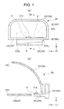
- FIG. 1 (a) and FIG. 1 (b) are views showing a case in which the lamp 20 is removed from the vehicle lighting device 10, wherein FIG. 1 (a) is a front view when seen from the side of the opening 23C of the reflector 23, and FIG. 1 (b) is a sectional view taken along the line b-b of FIG. 1 (a) . It is to be noted that the sectional view of FIG. 1 (b) coincides with a sectional view of the lamp 20 shown in FIG. 2 .
- the heat sink 22 is made of: a heat sin main body 22A that is supported with respect to the housing 13; and a plate-shaped light source mount member 22B which is protruded from the heat sink main body 22A and on which the light emitting diode 21 is to be disposed.
- the heat sink main body 22A is disposed on a rear side of the reflector 23, for example; has a comparatively large capacity; and is structured in such a manner that a surface area is increased by a heat radiation fin, although not shown, thereby increasing a heat radiation effect.
- the light source mount member 22B is formed as a plate-shaped member that is protruded from the heat sink main body 22A to the side of the opening 23C of the reflector 23.
- This light source mount member 22B is mounted integrally with the heat sink member 22A, for example, and is made of a metal or a resin material with its high heat conductivity. In this manner, the light source mount member 22B is a so called cantilever structure with respect to the heat sink main body 22A.
- the light source mount member 22B is adapted to mount the light emitting diode 21 thereon, as described above, a part of the heat from the light emitting diode 21 is thermally radiated by means of the light source mount member 22B, and the remaining heat that is a majority of the generated heat is transmitted to the side of the heat sink main body 22A so as to be thermally radiated by means of the heat sink main body 22A.
- the light source mount member 22B as shown in FIG. 1 (a) , is structured to be mounted on the heat sink main body 22A in such a manner that a side end face on the right side in the figure (reference numeral 22BR in the figure) is formed to be higher than a side end face on the left side in the figure (reference numeral 22BL in the figure) so that a surface on which the light emitting diode 21 is to be mounted has a tilt of an angle ⁇ .
- the light source mount member 22B is configured to be mounted on the heat sink member 22A so as to be disposed to tilt at an angle ⁇ with respect to a horizontal surface in a widthwise direction of the vehicle (on the x-y plane in the figure) in a case where the vehicle lighting device 10 is mounted on a vehicle.
- the aforementioned angle ⁇ is set in a range of 0 degree ⁇ ⁇ ⁇ 45 degrees, or preferably, in a range of 5 degrees ⁇ ⁇ ⁇ 15 degrees.
- the light emitting diode 21 is disposed on the light source mount member 22B so that the light emission surface 21A is substantially flush with the horizontal surface in the widthwise direction of the vehicle (the x-y plane in the figure) in the vehicle lighting device 10 is mounted on a vehicle in spite of the fact that the light source mount member 22B is disposed to be tilted. In this manner, optical distribution of the light from the light emitting diode 21 can be made for the existing reflector 23.
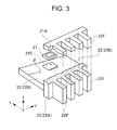
- FIG. 3 is a partially cutaway perspective view showing the thus configured heat sink 22.
- the light source mount member 22B is mount on the heat sink main body 22A so that a surface on which the light emitting diode 21 is to be mounted has a tilt of an angle ⁇ with respect to a horizontal surface in a widthwise direction of a vehicle (in the x-y plane in the figure) and then the light emitting diode 21 is mounted via a base portion 22E that is integrally provided on the light source mount member 22B, for example, whereby the light emission surface 21A is substantially flush with the horizontal surface in the widthwise direction of the vehicle (the x-y plane in the figure).
- a plurality of heat radiation fins 22F are formed which is provided in parallel to each other in the widthwise direction of the vehicle (in the y direction in the figure), and which extends in a vertical direction of the vehicle (in the z direction in the figure).
- FIG. 4 is a view when the heat sink 22 made of the heat sink main body 22A and the light source mount member 22B is seen from the front side of the vehicle, wherein the light emitting diode 21 is not shown. As is evident from FIG.
- the plate-shaped light source mount member 22B is disposed integrally with the heat sink main body 22A so as to have a tilt of an angle ⁇ (0 degree ⁇ ⁇ ⁇ 45 degrees) with respect to the horizontal surface in the widthwise direction of the vehicle in a case where the vehicle lighting device 10 is mounted on the vehicle.
- a width of the light source mount member 22B is defined as L in a case where the light source mount member 22B made of a cantilever structure is disposed in parallel to the horizontal surface in the widthwise direction of the vehicle, as shown in FIG. 4 in a case where the light source mount member 22B is caused to tilt at an angle of ⁇ , the width of the light source mount member 22B is obtained as L/cosine ⁇ , which can be greater than L, making it possible to increase rigidity.
- the light source mount member 22B can be formed in such as manner as to be reduced in thickness, or alternatively, the light source mount member 22B made of a cantilever structure can be increased in length, and an advantageous effect of improving a degree of freedom in design of the light source mount member 22B is attained.
- FIG. 7 (a) and FIG. 7 (b) are views each showing a configuration of the heat sink 22 of the lamp 20 shown in the first embodiment in which in a case where the vehicle lighting device 10 is mounted on a vehicle, the light source mount member 22B is disposed in parallel to the horizontal surface in the widthwise direction of the vehicle (in the x-y plane in the figure).
- this external force F is not reduced, and serves as a force to slacken the light source mount member 22B of a cantilever structure as it is, and there occurs an inconvenience that the light source mount member 22B easily resonates with such vibration.
- the vehicle lighting device of the present invention there can be provided a structure that is capable of, with respect to vibration of a vehicle, restraining vibration of the light source mount member 22B of the heat sink 22 adapted to mount a light emitting diode.
- the light emitting diode 21 shown in the first embodiment is disposed on the light source mount member 22B so that the light emission surface 21A is substantially flush with the horizontal surface in the widthwise direction of the vehicle in a case where the vehicle lighting device 10 is mounted on the vehicle.
- the light emitting diode 21 may be disposed on the light source mount member 22B so that the light emission surface 21 A tilts with respect to the horizontal surface in the widthwise direction of the vehicle (the x-y plane in the figure).
- light from the light emitting diode can be emitted to the front lens side in a predetermined light distribution state by changing a design of a light reflection surface of a reflector. From the foregoing scope of work, it is needless to say that the light emitting diode 21 may be mounted to tilt in a forward/backward direction of a vehicle (in the x direction in the figure).
- heat sink 22 shown in the first embodiment has been described as a heat sink in which the heat sink main body 22A and the light source mount member 22B are integrally provided respectively, of course, these heat sink main body 22A and light source mount member 22B may be separately formed respectively, and for example, these elements may be configured to be combined with each other by means of screw or the like.
- the light source mount member 22B adapted to mount the light emitting diode 21 is caused to tilt so that the vehicle outside is high and the vehicle inside is low, for example, with respect to the horizontal surface in the widthwise direction of the vehicle.
- the light source mount member 22B may be caused to tilt so that the vehicle outside is low and the vehicle inside is high with respect to the horizontal surface in the widthwise direction of the vehicle. Even in such a case, an advantageous effect similar to the above described effect can be obtained.
- the vehicle lighting device 10 that has been shown in the first embodiment is also shown as a vehicle lighting device that is structured in such a manner that, in a case where the lighting device is mounted on a vehicle, a reflector 23 is disposed upward of the light emitting diode 21.
- a reflector 23 is disposed upward of the light emitting diode 21.
- FIG. 6 is a view showing, in association with FIG. 1 , a vehicle lighting device that is structured in such a manner that the reflector 23 is disposed downward of the light emitting diode 21.
- the heat sink 22 is made of the heat sink main body 22A and the light source mount member 22B on which the light emitting diode is disposed; and the light source mount member 22B is made of a plate-shaped member that is protruded from the heat sink main body 22A to the side of the opening 23C of the reflector 23, and in a case where the vehicle lighting device 10 is mounted on the vehicle, the lighting device is disposed so as to tilt at an angle ⁇ with respect to the horizontal surface in the widthwise direction of the vehicle (the x-y plane in the figure).
Landscapes
- Engineering & Computer Science (AREA)
- General Engineering & Computer Science (AREA)
- Physics & Mathematics (AREA)
- Microelectronics & Electronic Packaging (AREA)
- Optics & Photonics (AREA)
- Non-Portable Lighting Devices Or Systems Thereof (AREA)
- Lighting Device Outwards From Vehicle And Optical Signal (AREA)
Applications Claiming Priority (1)
| Application Number | Priority Date | Filing Date | Title |
|---|---|---|---|
| JP2011193074A JP2013054959A (ja) | 2011-09-05 | 2011-09-05 | 車両用灯具 |
Publications (2)
| Publication Number | Publication Date |
|---|---|
| EP2565523A2 true EP2565523A2 (fr) | 2013-03-06 |
| EP2565523A3 EP2565523A3 (fr) | 2017-03-15 |
Family
ID=46762962
Family Applications (1)
| Application Number | Title | Priority Date | Filing Date |
|---|---|---|---|
| EP12182928.7A Withdrawn EP2565523A3 (fr) | 2011-09-05 | 2012-09-04 | Dispositif d'éclairage de véhicule |
Country Status (3)
| Country | Link |
|---|---|
| US (1) | US8556481B2 (fr) |
| EP (1) | EP2565523A3 (fr) |
| JP (1) | JP2013054959A (fr) |
Families Citing this family (3)
| Publication number | Priority date | Publication date | Assignee | Title |
|---|---|---|---|---|
| KR101529166B1 (ko) * | 2013-08-06 | 2015-06-16 | 현대모비스 주식회사 | 차량용 램프 |
| US20150167919A1 (en) * | 2013-12-17 | 2015-06-18 | Ford Global Technologies, Llc | Vehicle Lamp Assembly |
| KR102148512B1 (ko) | 2017-09-01 | 2020-08-27 | 주식회사 엘지화학 | 양극 활물질의 제조방법 및 이를 이용한 양극 활물질 및 리튬 이차전지 |
Citations (1)
| Publication number | Priority date | Publication date | Assignee | Title |
|---|---|---|---|---|
| JP2010086944A (ja) | 2008-09-08 | 2010-04-15 | Koito Mfg Co Ltd | 車両用赤外光照射ランプ |
Family Cites Families (14)
| Publication number | Priority date | Publication date | Assignee | Title |
|---|---|---|---|---|
| US6705745B1 (en) * | 1999-06-08 | 2004-03-16 | 911Ep, Inc. | Rotational led reflector |
| JP2006127963A (ja) * | 2004-10-29 | 2006-05-18 | Hitachi Ltd | 配光制御デバイス |
| JP4640962B2 (ja) * | 2005-07-29 | 2011-03-02 | 株式会社小糸製作所 | 車両用前照灯 |
| JP4780777B2 (ja) * | 2006-09-27 | 2011-09-28 | スタンレー電気株式会社 | 車両用led灯具 |
| WO2008084882A1 (fr) * | 2007-01-12 | 2008-07-17 | Panasonic Corporation | Dispositif électroluminescent et appareil d'éclairage utilisant celui-ci |
| JP4926770B2 (ja) * | 2007-03-15 | 2012-05-09 | 株式会社小糸製作所 | 車両用前照灯装置 |
| KR100923140B1 (ko) * | 2007-12-18 | 2009-10-23 | 에스엘 주식회사 | Led방열 장치 |
| US7762700B2 (en) * | 2008-05-28 | 2010-07-27 | Osram Sylvania Inc. | Rear-loaded light emitting diode module for automotive rear combination lamps |
| JP5297708B2 (ja) * | 2008-07-08 | 2013-09-25 | 株式会社小糸製作所 | 光源モジュール |
| WO2010026522A1 (fr) * | 2008-09-05 | 2010-03-11 | Philips Intellectual Property & Standards Gmbh | Ensemble de lampe |
| JP5264448B2 (ja) * | 2008-12-02 | 2013-08-14 | 株式会社小糸製作所 | 投射型の車両用灯具 |
| JP5218115B2 (ja) * | 2009-02-03 | 2013-06-26 | 市光工業株式会社 | 車両用灯具 |
| JP5457061B2 (ja) * | 2009-04-01 | 2014-04-02 | 株式会社小糸製作所 | 車両用前照灯 |
| JP2011171121A (ja) * | 2010-02-18 | 2011-09-01 | Ichikoh Ind Ltd | 車両用前照灯 |
-
2011
- 2011-09-05 JP JP2011193074A patent/JP2013054959A/ja active Pending
-
2012
- 2012-09-04 EP EP12182928.7A patent/EP2565523A3/fr not_active Withdrawn
- 2012-09-04 US US13/602,869 patent/US8556481B2/en not_active Expired - Fee Related
Patent Citations (1)
| Publication number | Priority date | Publication date | Assignee | Title |
|---|---|---|---|---|
| JP2010086944A (ja) | 2008-09-08 | 2010-04-15 | Koito Mfg Co Ltd | 車両用赤外光照射ランプ |
Also Published As
| Publication number | Publication date |
|---|---|
| US20130058118A1 (en) | 2013-03-07 |
| US8556481B2 (en) | 2013-10-15 |
| CN102980116A (zh) | 2013-03-20 |
| EP2565523A3 (fr) | 2017-03-15 |
| JP2013054959A (ja) | 2013-03-21 |
Similar Documents
| Publication | Publication Date | Title |
|---|---|---|
| KR101231406B1 (ko) | 차량용 전조등 | |
| US10514158B2 (en) | Light source device and projection device | |
| JP5287324B2 (ja) | 車両用灯具 | |
| EP2378323B1 (fr) | Lampe de véhicule | |
| US9885455B2 (en) | Vehicle lamp | |
| KR101548435B1 (ko) | 회로 모듈, 발광 모듈 및 차량용 등기구 | |
| JP2010238604A (ja) | 発光素子モジュール化部材および灯具ユニット | |
| US9035346B2 (en) | Light source module | |
| US8632232B2 (en) | Vehicular headlamp having a columnar light guide | |
| CN105247274B (zh) | 车辆用灯具 | |
| CN105247273B (zh) | 车辆用灯具 | |
| EP3660390B1 (fr) | Lampe de véhicule | |
| JP5614001B2 (ja) | 車両用灯具 | |
| US8556481B2 (en) | Vehicle lighting device | |
| JP6060677B2 (ja) | 車両用灯具 | |
| US20110249459A1 (en) | Vehicle light | |
| JP2014165150A (ja) | 車両用灯具 | |
| US20120314441A1 (en) | Automotive lamp | |
| JP4677971B2 (ja) | 車両用灯具 | |
| JP2020095876A (ja) | 車両用灯具 | |
| US12435851B2 (en) | Lamp fitting, and vehicular headlamp | |
| US9353925B2 (en) | Vehicular lamp with optical member having thermal stress absorption features | |
| JP2010165464A (ja) | 光源装置の製造方法および光源装置 | |
| JP6372061B2 (ja) | 車両用灯具 | |
| CN215267062U (zh) | 一种激光器外壳及半导体激光器 |
Legal Events
| Date | Code | Title | Description |
|---|---|---|---|
| PUAI | Public reference made under article 153(3) epc to a published international application that has entered the european phase |
Free format text: ORIGINAL CODE: 0009012 |
|
| AK | Designated contracting states |
Kind code of ref document: A2 Designated state(s): AL AT BE BG CH CY CZ DE DK EE ES FI FR GB GR HR HU IE IS IT LI LT LU LV MC MK MT NL NO PL PT RO RS SE SI SK SM TR |
|
| AX | Request for extension of the european patent |
Extension state: BA ME |
|
| PUAL | Search report despatched |
Free format text: ORIGINAL CODE: 0009013 |
|
| AK | Designated contracting states |
Kind code of ref document: A3 Designated state(s): AL AT BE BG CH CY CZ DE DK EE ES FI FR GB GR HR HU IE IS IT LI LT LU LV MC MK MT NL NO PL PT RO RS SE SI SK SM TR |
|
| AX | Request for extension of the european patent |
Extension state: BA ME |
|
| RIC1 | Information provided on ipc code assigned before grant |
Ipc: F21V 29/00 20150101ALI20170203BHEP Ipc: F21V 19/00 20060101ALI20170203BHEP Ipc: F21S 8/10 20060101AFI20170203BHEP |
|
| STAA | Information on the status of an ep patent application or granted ep patent |
Free format text: STATUS: REQUEST FOR EXAMINATION WAS MADE |
|
| 17P | Request for examination filed |
Effective date: 20170915 |
|
| RBV | Designated contracting states (corrected) |
Designated state(s): AL AT BE BG CH CY CZ DE DK EE ES FI FR GB GR HR HU IE IS IT LI LT LU LV MC MK MT NL NO PL PT RO RS SE SI SK SM TR |
|
| STAA | Information on the status of an ep patent application or granted ep patent |
Free format text: STATUS: EXAMINATION IS IN PROGRESS |
|
| 17Q | First examination report despatched |
Effective date: 20210329 |
|
| STAA | Information on the status of an ep patent application or granted ep patent |
Free format text: STATUS: THE APPLICATION IS DEEMED TO BE WITHDRAWN |
|
| 18D | Application deemed to be withdrawn |
Effective date: 20220126 |