EP2565535A2 - Dispositif dýéclairage - Google Patents
Dispositif dýéclairage Download PDFInfo
- Publication number
- EP2565535A2 EP2565535A2 EP12176634A EP12176634A EP2565535A2 EP 2565535 A2 EP2565535 A2 EP 2565535A2 EP 12176634 A EP12176634 A EP 12176634A EP 12176634 A EP12176634 A EP 12176634A EP 2565535 A2 EP2565535 A2 EP 2565535A2
- Authority
- EP
- European Patent Office
- Prior art keywords
- engaging
- holding
- mounting unit
- light source
- claw
- Prior art date
- Legal status (The legal status is an assumption and is not a legal conclusion. Google has not performed a legal analysis and makes no representation as to the accuracy of the status listed.)
- Granted
Links
- 238000005286 illumination Methods 0.000 title claims abstract description 33
- 210000000078 claw Anatomy 0.000 claims description 98
- 230000003014 reinforcing effect Effects 0.000 description 4
- 125000006850 spacer group Chemical group 0.000 description 4
- -1 acryl Chemical group 0.000 description 1
- 229920000122 acrylonitrile butadiene styrene Polymers 0.000 description 1
- XAGFODPZIPBFFR-UHFFFAOYSA-N aluminium Chemical compound [Al] XAGFODPZIPBFFR-UHFFFAOYSA-N 0.000 description 1
- 229910052782 aluminium Inorganic materials 0.000 description 1
- 239000003086 colorant Substances 0.000 description 1
- 238000003780 insertion Methods 0.000 description 1
- 230000037431 insertion Effects 0.000 description 1
- 238000010030 laminating Methods 0.000 description 1
- 238000004519 manufacturing process Methods 0.000 description 1
- 239000000463 material Substances 0.000 description 1
- 239000007769 metal material Substances 0.000 description 1
- 238000012986 modification Methods 0.000 description 1
- 230000004048 modification Effects 0.000 description 1
- 150000002894 organic compounds Chemical class 0.000 description 1
- 239000011368 organic material Substances 0.000 description 1
- 229920003023 plastic Polymers 0.000 description 1
- 239000004033 plastic Substances 0.000 description 1
- 229920005990 polystyrene resin Polymers 0.000 description 1
- 238000003825 pressing Methods 0.000 description 1
- 229920005989 resin Polymers 0.000 description 1
- 239000011347 resin Substances 0.000 description 1
- 230000000452 restraining effect Effects 0.000 description 1
- 230000000717 retained effect Effects 0.000 description 1
- 239000000758 substrate Substances 0.000 description 1
Images


Classifications
-
- F—MECHANICAL ENGINEERING; LIGHTING; HEATING; WEAPONS; BLASTING
- F21—LIGHTING
- F21V—FUNCTIONAL FEATURES OR DETAILS OF LIGHTING DEVICES OR SYSTEMS THEREOF; STRUCTURAL COMBINATIONS OF LIGHTING DEVICES WITH OTHER ARTICLES, NOT OTHERWISE PROVIDED FOR
- F21V19/00—Fastening of light sources or lamp holders
- F21V19/04—Fastening of light sources or lamp holders with provision for changing light source, e.g. turret
-
- F—MECHANICAL ENGINEERING; LIGHTING; HEATING; WEAPONS; BLASTING
- F21—LIGHTING
- F21S—NON-PORTABLE LIGHTING DEVICES; SYSTEMS THEREOF; VEHICLE LIGHTING DEVICES SPECIALLY ADAPTED FOR VEHICLE EXTERIORS
- F21S8/00—Lighting devices intended for fixed installation
- F21S8/04—Lighting devices intended for fixed installation intended only for mounting on a ceiling or the like overhead structures
-
- F—MECHANICAL ENGINEERING; LIGHTING; HEATING; WEAPONS; BLASTING
- F21—LIGHTING
- F21V—FUNCTIONAL FEATURES OR DETAILS OF LIGHTING DEVICES OR SYSTEMS THEREOF; STRUCTURAL COMBINATIONS OF LIGHTING DEVICES WITH OTHER ARTICLES, NOT OTHERWISE PROVIDED FOR
- F21V15/00—Protecting lighting devices from damage
- F21V15/01—Housings, e.g. material or assembling of housing parts
-
- F—MECHANICAL ENGINEERING; LIGHTING; HEATING; WEAPONS; BLASTING
- F21—LIGHTING
- F21V—FUNCTIONAL FEATURES OR DETAILS OF LIGHTING DEVICES OR SYSTEMS THEREOF; STRUCTURAL COMBINATIONS OF LIGHTING DEVICES WITH OTHER ARTICLES, NOT OTHERWISE PROVIDED FOR
- F21V21/00—Supporting, suspending, or attaching arrangements for lighting devices; Hand grips
- F21V21/02—Wall, ceiling, or floor bases; Fixing pendants or arms to the bases
-
- F—MECHANICAL ENGINEERING; LIGHTING; HEATING; WEAPONS; BLASTING
- F21—LIGHTING
- F21V—FUNCTIONAL FEATURES OR DETAILS OF LIGHTING DEVICES OR SYSTEMS THEREOF; STRUCTURAL COMBINATIONS OF LIGHTING DEVICES WITH OTHER ARTICLES, NOT OTHERWISE PROVIDED FOR
- F21V17/00—Fastening of component parts of lighting devices, e.g. shades, globes, refractors, reflectors, filters, screens, grids or protective cages
- F21V17/10—Fastening of component parts of lighting devices, e.g. shades, globes, refractors, reflectors, filters, screens, grids or protective cages characterised by specific fastening means or way of fastening
- F21V17/18—Latch-type fastening, e.g. with rotary action
-
- F—MECHANICAL ENGINEERING; LIGHTING; HEATING; WEAPONS; BLASTING
- F21—LIGHTING
- F21Y—INDEXING SCHEME ASSOCIATED WITH SUBCLASSES F21K, F21L, F21S and F21V, RELATING TO THE FORM OR THE KIND OF THE LIGHT SOURCES OR OF THE COLOUR OF THE LIGHT EMITTED
- F21Y2105/00—Planar light sources
-
- F—MECHANICAL ENGINEERING; LIGHTING; HEATING; WEAPONS; BLASTING
- F21—LIGHTING
- F21Y—INDEXING SCHEME ASSOCIATED WITH SUBCLASSES F21K, F21L, F21S and F21V, RELATING TO THE FORM OR THE KIND OF THE LIGHT SOURCES OR OF THE COLOUR OF THE LIGHT EMITTED
- F21Y2115/00—Light-generating elements of semiconductor light sources
- F21Y2115/10—Light-emitting diodes [LED]
- F21Y2115/15—Organic light-emitting diodes [OLED]
-
- G—PHYSICS
- G09—EDUCATION; CRYPTOGRAPHY; DISPLAY; ADVERTISING; SEALS
- G09F—DISPLAYING; ADVERTISING; SIGNS; LABELS OR NAME-PLATES; SEALS
- G09F13/00—Illuminated signs; Luminous advertising
- G09F13/04—Signs, boards or panels, illuminated from behind the insignia
Definitions
- the present invention relates to an illumination device in which a solid-state light emitting element such as an organic EL element or the like is used as a light source.
- An organic EL element is capable of emitting high-brightness light at a low voltage and capable of producing different emission colors depending on the kind of an organic compound.
- the organic EL element can be easily formed into a planar light emitting panel. In recent years, attention is paid to the use of the organic EL element as a light source for an illumination device.
- an illumination device using an organic EL element as a light emitting panel the light emitting panel needs to be replaced if the light emitting panel reaches its lifespan or if a user wishes to use a light emitting panel differing in size or kind. Therefore, it is desirable that the illumination device using an organic EL element as a light emitting panel be configured so that the light emitting panel can be replaced with ease.
- Japanese Patent Application Publication No. 2009-129766 discloses an EL illumination device in which a light emitting panel having an organic EL element is used as a light source.
- the illumination device of this kind includes a mounting unit 100 attached to a ceiling or a wall and a light source unit 200 removably mounted to the mounting unit 100 and provided with a flat organic EL element.
- the light source unit 200 is mounted to the mounting unit 100 by respectively bringing an engaging portion 210 and a holding portion 220 thereof into engagement with an engaged portion 110 and a held portion 120 of the mounting unit 100.
- the joint areas between the engaging members namely, the engaged portion 110, the held portion 120, the engaging portion 210 and the holding portion 220
- the engaging members are likely to be broken if the strength of the engaging members is low and if a large force is applied to the engaging members.
- the size of the engaging members and the joint areas between the engaging members and the mounting unit 100 or the light source unit 200 are increased in an effort to increase the strength of the engaging members, it is likely that the engaging members may interfere with other members. This may lead to an increase in the total thickness of the illumination device.
- the present invention provides an illumination device having a removably mounted light source unit, which is capable of restraining interference of engaging members with other members while increasing the strength of the engaging members and capable of reducing the total thickness of the illumination device.
- an illumination device including: a mounting unit adopted to be attached to a ceiling or a wall; and a light source unit removably mounted to the mounting unit and provided with a flat light emitting panel, wherein the mounting unit includes an engaged portion provided in one end portion of a mounting surface to which the light source unit is mounted and a held portion provided in the other end portion of the mounting surface opposing to said one end portion, the light source unit includes a package configured to cover the light emitting panel and an engaging portion and a holding portion arranged on the surface of the package facing the mounting unit, the engaging portion and the holding portion protruding toward the mounting unit, the engaging portion is arranged to engage with the engaged portion and the holding portion is arranged to engage with the held portion, and the engaging portion and the holding portion have mutually-opposing slant surfaces, the slant surfaces being inclined toward a center of the light source unit so as to increase a joint area of the engaging portion and the holding portion with respect to the package.
- the light source unit may be swingable with respect to the mounting unit in a state that the engaging portion engages with the engaged portion.
- the engaged portion may be provided in one end portion of the mounting surface to be slidable toward the held portion.
- the held portion may be provided with a holding claw extending toward the engaged portion.
- the holding portion may be provided with a holding claw engaging with the holding claw of the held portion.
- the holding claws of the held portion and the holding portion may include engaging surfaces engageable with each other and non-engaging surfaces formed at the opposite sides of the engaging surfaces.
- the holding claw of the held portion when seen in a vertical cross section taken through the engaged portion and the held portion in a state that the mounting unit and the light source unit are combined together, the holding claw of the held portion may be formed such that a tip end of the holding claw of the held portion on the non-engaging surface is positioned nearer to the mounting unit than a base end of the holding claw of the held portion on the non-engaging surface or the holding claw of the holding portion may be formed such that a tip end of the holding claw of the holding portion on the non-engaging surface is positioned nearer to the light source unit than a base end of the holding claw of the holding portion on the non-engaging surface.
- the light source unit may be swingable with respect to the mounting unit in a state that the engaging portion engages with the engaged portion.
- the engaged portion may be provided in one end portion of the mounting surface to slide toward the held portion.
- the held portion may be provided with a holding claw extending toward the engaged portion.
- the holding portion may be provided with a holding claw engaging with the holding claw of the held portion.
- the holding claws of the held portion and the holding portion include engaging surfaces engageable with each other.
- the holding claw of the held portion When seen in a vertical cross section taken through the engaged portion and the held portion in a state that the mounting unit and the light source unit are combined together, the holding claw of the held portion may be formed such that a tip end of the holding claw of the held portion on the engaging surface is positioned nearer to the light source unit than a base end of the holding claw of the held portion on the engaging surface or the holding claw of the holding portion may be formed such that a tip end of the holding claw of the holding portion on the engaging surface is positioned nearer to the mounting unit than a base end of the holding claw of the holding portion on the engaging surface.
- the engaged portion may be provided with an engaging claw extending toward the held portion.
- the engaging portion may be provided with an engaging claw engaging with the engaging claw of the engaged portion.
- the engaging claws of the engaged portion and the engaging portion may include engaging surfaces engageable with each other.
- the engaging claw of the engaged portion When seen in a vertical cross section taken through the engaged portion and the held portion in a state that the mounting unit and the light source unit are combined together, the engaging claw of the engaged portion may be formed such that a tip end of the engaging claw of the engaged portion on the engaging surface is positioned nearer to the light source unit than the base end of the engaging claw of the engaged portion on the engaging surface or the engaging claw of the engaging portion may be formed such that the tip end of the engaging claw of the engaging portion on the engaging surface is positioned nearer to the mounting unit than the base end of the engaging claw of the engaging portion on the engaging surface.
- the package may include a bevel surface formed by chamfering an end portion of the package which exists near the engaging portion and faces the mounting unit.
- the package may be configured such that the engaged portion and the engaging portion are positioned to engage with each other when the engaged portion and the engaging portion are moved toward each other in a state that the bevel surface makes contact with the mounting surface of the mounting unit.
- the bevel surface may be parallel or substantially parallel to the non-engaging surface of the engaging portion.
- the engaged portion may be provided to have a playing gap so that the engaged portion can be tilted with respect to the mounting unit.
- the engaged portion may include a salient portion provided on the outer surface thereof facing the held portion and positioned at the side of the light source unit.
- the salient portion may engage with a step formed in the mounting unit so as to prevent the engaged portion from being separated from the mounting unit.
- the regions of the engaging portion and the holding portion leading to the package are formed into slant surfaces.
- the joint area of the engaging portion and the holding portion with respect to the package grows larger. This helps increase the strength of the engaging portion and the holding portion. This makes it difficult for the engaging portion and the holding portion to interfere with other members. It is therefore possible to reduce the total thickness of the illumination device.
- the illumination device 1 includes a mounting unit 2 attached to a ceiling or a wall and provided with a housing, and a light source unit 3 removably mounted to the mounting unit 2.
- the mounting unit 2 has a rectangular shape when seen from the side of a light irradiation surface.
- the mounting unit 2 includes an engaged portion 21 and a held portion 22 provided on a mounting surface 2A on which the light source unit 3 is mounted.
- the engaged portion 21 is provided in the central area of one side (one end portion) of the rectangular mounting unit 2.
- the held portion 22 is provided in the central area of the other side (the other end portion) of the rectangular mounting unit 2 opposing to said one side.
- the light source unit 3 has a rectangular shape when seen from the side of the light irradiation surface.
- the light source unit 3 includes a flat light emitting panel 40 and a package 30 for accommodating the light emitting panel 40.
- the light source unit 3 includes an engaging portion 31 and a holding portion 32 provided on the surface of the package 30 facing the mounting unit 2.
- the engaging portion 31 and the holding portion 32 protrude toward the mounting unit 2.
- the mutually opposing surfaces 31a and 32a of the engaging portion 31 and the holding portion 32 are formed into slant surfaces inclined toward the center of the light source unit 3 (see Figs. 6 and 7 ).
- the joint area of the engaging portion 31 and the holding portion 32 with respect to the package 30 grows larger.
- the engaging portion 31 and the holding portion 32 occupy a reduced space. This helps increase the effective space within the illumination device 1.
- the engaging portion 31 engages with the engaged portion 21.
- the holding portion 32 engages with the held portion 22.
- the light source unit 3 is removably mounted to the mounting unit 2.
- the light source unit 3 is swingable with respect to the mounting unit 2 in a state that the engaging portion 31 engages with the engaged portion 21 of the mounting unit 2 (see Fig. 5 ).
- the mounting unit 2 is attached to a ceiling or a wall by screws 24 inserted into screw holes 23.
- the mounting unit 2 includes a circuit board 25 for controlling energization of the light source unit 3 and a terminal reception portion 26 led out from the circuit board 25.
- a terminal portion 33 of the package 30 protruding toward the mounting unit 2 is inserted into the terminal reception portion 26.
- the mounting unit 2 and the light source unit 3 are electrically connected to each other.
- the light source unit 3 includes a light emitting panel 40 electrically connected to the terminal portion 33.
- the light emitting panel 40 is formed of a solid-state light emitting element, e.g., an organic EL element.
- the organic EL element is formed by, e.g., laminating a light-transmitting substrate, a positive electrode made of a transparent conductive film, a light emitting layer containing a light-emitting organic material, and a light-reflecting negative electrode, in the named order from the side of a light emission surface.
- the package 30 includes a cover 30a for covering the light emission surface of the light emitting panel 40 and a case 30b for covering the non-light-emission surface of the light emitting panel 40.
- the cover 30a is formed of a transparent rectangular flat member.
- the case 30b is formed into a box shape and is opened on one surface.
- the cover 30a is attached to the opening of the case 30b.
- the case 30b is made of, e.g., a plastic material such as an ABS resin, an acryl resin or a polystyrene resin, or a metallic material such as aluminum or the like, the surface of which is subjected to an insulating treatment.
- the case 30b includes bevel surfaces 34 formed by chamfering the end portion of the case 30b which exists near the engaging portion 31 and faces the mounting unit 2 and by chamfering the end portion of the case 30b which exists near the holding portion 32 and faces the mounting unit 2.
- the inclination of the bevel surfaces 34 is set such that the engaged portion 21 and the engaging portion 31 are positioned to engage with each other when the light source unit 3 is brought into contact with the mounting surface 2A of the mounting unit 2 through the bevel surface 34 existing near the engaging portion 31 and when the light source unit 3 is moved toward the engaged portion 21 in that state.
- the case 30b includes a plurality of spacers 35 formed near the engaging portion 31 and the holding portion 32. The spacers 35 create a gap between the light source unit 3 and the mounting unit 2 when the light source unit 3 is mounted to the mounting unit 2.
- the held portion 22 includes a holding claw 22a extending toward the engaged portion 21.
- the holding portion 32 includes a holding claw 32b engaging with the holding claw 22a.
- the tip end 22b of the holding claw of the held portion 22 is positioned nearer to the light source unit 3 (namely, nearer to the light emitting panel 40) than the base end 22d of the holding claw of the held portion 22 on the engaging surface 22c engaging with the holding portion 32.
- the tip end 22b of the holding claw of the held portion 22 is positioned nearer to the mounting unit 2 (namely, farther from the light emitting panel 40) than the base end 22f of the holding claw of the held portion 22 on the non-engaging surface 22e existing at the opposite side of the engaging surface 22c.
- the tip end 32c of the holding claw of the holding portion 32 is positioned nearer to the mounting unit 2 than the base end 32e of the holding claw of the holding portion 32 on the engaging surface 32d engaging with the held portion 22 and is positioned nearer to the light source unit 3 than the base end 32g of the holding claw of the holding portion 32 on the non-engaging surface 32f.
- the holding claw 22a of the held portion 22 is formed such that the tip end 22b of the holding claw 22a of the held portion 22 on the non-engaging surface 22e is positioned nearer to the mounting unit 2 than the base end 22f of the holding claw 22a of the held portion 22 on the non-engaging surface 22e.
- the holding claw 32b of the holding portion 32 is formed such that the tip end 32c of the holding claw 32b of the holding portion 32 on the non-engaging surface 32f is positioned nearer to the light source unit 3 than the base end 32g of the holding claw 32b of the holding portion 32 on the non-engaging surface 32f.
- the engaged portion 21 includes an engaging claw 21a extending toward the held portion 22.
- the engaging portion 31 includes an engaging claw 31b engaging with the engaging claw 21a of the engaged portion 21.
- the tip end 21b of the engaging claw of the engaged portion 21 is positioned nearer to the light source unit 3 than the base end 21d of the engaging claw of the engaged portion 21 on the engaging surface 21c engaging with the engaging portion 31.
- the tip end 31c of the engaging claw of the engaging portion 31 is positioned nearer to the mounting unit 2 than the base end 31e of the engaging claw of the engaging portion 31 on the engaging surface 31d engaging with the engaged portion 21.
- the non-engaging surface 31f of the engaging portion 31 is formed parallel or substantially parallel to the bevel surface 34 existing near the engaging portion 31.
- the engaging claw 21a of the engaged portion 21 is formed such that the tip end 21b of the engaging claw of the engaged portion 21 on the engaging surface 21c is positioned nearer to the light source unit 3 than the base end 21d of the engaging claw of the engaged portion 21 on the engaging surface 21c.
- the engaging claw 31b of the engaging portion 31 is formed such that the tip end 31c of the engaging claw of the engaging portion 31 on the engaging surface 31d is positioned nearer to the mounting unit 2 than the base end 31e of the engaging claw of the engaging portion 31 on the engaging surface 31d.
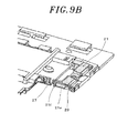
- the engaged portion 21 (indicated by dots) is resiliently biased toward the held portion 22 by a spring 4 and is mounted to the mounting unit 2 in a slidable manner.
- Fig. 9A shows a state that the engaged portion 21 positioned closest to the held portion 22
- Fig. 9B shows a state that the engaged portion 21 is positioned farthest from the held portion 22. No spring is shown in Figs. 9A and 9B .
- the engaged portion 21 includes not only the engaging claw 21a stated above but also groove portion 21e provided at the opposite sides of the engaging claw 21a.
- Each of the groove portions 21e has a groove extending in the direction orthogonal to the extension direction of the engaging claw 21a.
- the spring 4 is accommodated within the groove.
- the engaged portion 21 further includes salient portions 21f provided on the outer surface thereof facing the held portion 22 and positioned at the side of the light source unit 3 and protrusion portions 21g protruding from the outer surfaces of the groove portions 21e in the extension direction of the engaging claw 21a.
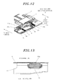
- the salient portions 21f engage with the steps 27 of the mounting unit 2, thereby preventing the engaged portion 21 from dropping from the mounting unit 2 (see Fig. 9A ).
- the protrusion portions 21g are involved in holding the engaged portion 21 with the mounting unit 2.
- the engaged portion 21 is introduced into the mounting unit 2 at the side of the surface (attachment surface) of the mounting unit 2 attached to a ceiling or a wall and is held in the mounting unit 2 with the protrusion portions 21g placed on the support portions 28 of the mounting unit 2.
- One end of the spring 4 is inserted into each of the groove portions 21e of the engaged portion 21.
- the other end of the spring 4 is retained by a resilient body support portion 29 provided in the mounting unit 2.
- a reinforcing plate 5 is arranged on the attachment surface of the engaged portion 21. The reinforcing plate 5 prevents the engaged portion 21 from dropping from the attachment surface. Consequently, as shown in Fig.
- the engaged portion 21 is held in the mounting unit 2 with the protrusion portions 21g interposed between the support portion 28 of the mounting unit 2 and the reinforcing plate 5.
- the engaged portion 21 is provided to have a playing gap so that the engaged portion 21 can be tilted with respect to the support portion 28 (the mounting unit 2) (the protrusion portions 21g in a tilted state is indicated by a dot line in Fig. 13 ).
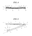
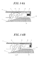
- the light source unit 3 is moved toward the engaged portion 21 in a state that bevel surface 34 of the light source unit 3 existing near the engaging portion 31 makes contact with the mounting surface 2A of the mounting unit 2 as shown in Fig. 5 .
- the engaged portion 21 and the engaging portion 31 are positioned to engage with each other as shown in Fig. 14A .
- the non-engaging surface 31f of the engaging portion 31 is kept parallel or substantially parallel to the bevel surface 34. Therefore, as compared with a case where an engaging portion 31 having a structure indicated by a dot line in Fig.
- the light source unit 3 is moved toward the held portion 22 as shown in Fig. 15B .
- the held portion 22 and the holding portion 32 come into engagement with each other.
- the engaged portion 21 engages with the engaging portion 31 while the held portion 22 engages with the holding portion 32.
- the light source unit 3 is mounted to the mounting unit 2.
- the light source unit 3 is swung toward the mounting unit 2 in the state shown in Fig. 5 without having to push the light source unit 3 toward the engaged portion 21.
- the held portion 22 and the holding portion 32 make contact with each other through the non-engaging surfaces 22e and 32f thereof.
- the non-engaging surfaces 22e and 32f are inclined so that the holding portion 32 can slide on the non-engaging surface 22e of the held portion 22 in such a direction as to engage with the held portion 22. Therefore, as shown in Fig.
- the holding portion 32 comes into contact with the held portion 22 and then slides on the non-engaging surface 22e of the held portion 22.
- the holding portion 32 comes into engagement with the held portion 22.
- the light source unit 3 may be mounted to the mounting unit 2 by converting the swing operation force to the sliding force for sliding the light source unit 3 toward the engaged portion 21, using the inclination of the non-engaging surfaces 22e and 32f of the held portion 22 and the holding portion 32.
- the operations for mounting the light source unit 3 to the mounting unit 2 are performed in the reverse order.
- the engagement of the held portion 22 and the holding portion 32 is first released by causing the light source unit 3 to slide toward the engaged portion 21.
- the end portion of the light source unit 3 near the holding portion 32 is swung in the direction in which the light source unit 3 is removed from the mounting unit 2.
- the engaging portion 31 is removed from the engaged portion 21.
- the engaging surfaces 21c and 31d of the engaged portion 21 and the engaging portion 31 are inclined so that the engagement of the engaged portion 21 and the engaging portion 31 can be released with ease (see Fig. 7 ). Since the engaged portion 21 is provided in the mounting unit 2 to have a playing gap, the engaging portion 31 is tilted in an easy-to-remove direction. It is therefore possible to easily remove the engaging portion 31 from the engaged portion 21.
- the light source unit 3 is removed from the mounting unit 2 by first sliding the light source unit 3 toward the engaged portion 21 and then swinging the light source unit 3. In some cases, however, the light source unit 3 may be directly swung without having to slide the light source unit 3.
- the engaging surfaces 22c and 32d of the held portion 22 and the holding portion 32 are inclined so that the holding portion 32 engaging with the held portion 22 can slide on the engaging surface 22c of the held portion 22 in such a direction as to be removed from the held portion 22 (see Fig. 6 ).
- the holding portion 32 is slid along the engaging surface 22c of the held portion 22 and is rapidly removed from the held portion 22.
- the light source unit 3 When removing the light source unit 3 from the mounting unit 2, the light source unit 3 is slid toward the held portion 22 by the resilient force of the spring 4 at the time point when the holding portion 32 is removed from the held portion 22. At this time, if the spacers 35 existing near the engaging portion 31 are allowed to interfere with the heads of the screws 24 as shown in Fig. 4 , the spacers 35 are placed on the heads of the screws 24, whereby the light source unit 3 floats upward from the mounting unit 2. Consequently, a space for insertion of a finger is created between the light source unit 3 and the mounting unit 2. Thus the task of removing the light source unit 3 can be performed with ease.
- the regions of the engaging portion 31 and the holding portion 32 leading to the package 30 are formed into slant surfaces.
- the joint area of the engaging portion 31 and the holding portion 32 with respect to the package 30 grows larger. This helps increase the strength of the engaging portion 31 and the holding portion 32.
- the effective space within the illumination device 1 gets increased, the interference between the respective members becomes smaller as compared with the conventional illumination device. It is therefore possible to reduce the total thickness of the illumination device 1 and to arrange an increased number of members within the illumination device 1. Since the mutually opposing surfaces 31a and 32a of the engaging portion 31 and the holding portion 32 are formed into slant surfaces, the effective space is formed in the central region of the illumination device 1.
- the non-engaging surfaces 22e and 32f of the held portion 22 and the holding portion 32 are inclined so that the held portion 22 and the holding portion 32 can smoothly engage with each other when the held portion 22 and the holding portion 32 are brought into contact with each other through the non-engaging surfaces 22e and 32f. This makes it easy to mount the light source unit 3 to the mounting unit 2.
- the engaging surfaces 22c and 32d are inclined so that the engagement of the held portion 22 and the holding portion 32 can be rapidly released when an excessive load is applied to the held portion 22 and the holding portion 32 due to an erroneous operation or other causes. This makes it possible to prevent damage of the held portion 22 and the holding portion 32.
- the engaging surfaces 21c and 31d of the engaged portion 21 and the engaging portion 31 are inclined so that the engagement of the engaged portion 21 and the engaging portion 31 can be released with ease when the light source unit 3 is removed from the mounting unit 2. This makes it easy to perform the task of removing the light source unit 3. Since the engaged portion 21 is provided in the mounting unit 2 to have a playing gap, it is easy to remove the engaging portion 31 from the engaged portion 21. It is also unlikely that an excessive force is applied to the engaged portion 21. This makes it possible to prevent damage of the engaged portion 21 and to prevent the engaged portion 21 from dropping from the mounting unit 2.
- the engaged portion 21 and the engaging portion 31 can be arranged in the mutually engaging positions by merely bringing the bevel surfaces 34 into contact with the mounting surface 2A of the mounting unit 2. This makes it easy to mount the light source unit 3 to the mounting unit 2.
- non-engaging surface 31f of the engaging portion 31 is parallel or substantially parallel to the bevel surface 34 of the case 30b existing near the engaging portion 31, it is possible to reduce the height of the mounting unit 2 and to reduce the total thickness of the illumination device 1.
- the engaged portion 21 is provided with the salient portions 21f, the engaged portion 21 is hardly dropped from the mounting unit 2 even before the reinforcing plate 5 is attached in the step of assembling the mounting unit 2 during the manufacturing process. This helps enhance the assembling efficiency of the illumination device 1.
- the illumination device is not limited to the embodiment described above but may be modified in many different forms.
- the light emitting body making up the light source unit is not limited to the organic EL element.
- the light emitting body may be formed of a solid-state light emitting element such as an inorganic EL element or an LED (Light Emitting Diode). While all the holding claws of the held portion and the holding portion have the slant non-engaging surface in the foregoing embodiment, only one of the holding claws may have the non-engaging surface. Similarly, only one of the holding claws of the held portion and the holding portion may have the slant engaging surface. Only one of the holding claws of the engaged portion and the engaging portion may have the slant engaging surface.
Landscapes
- Engineering & Computer Science (AREA)
- General Engineering & Computer Science (AREA)
- Fastening Of Light Sources Or Lamp Holders (AREA)
- Non-Portable Lighting Devices Or Systems Thereof (AREA)
- Planar Illumination Modules (AREA)
- Circuit Arrangement For Electric Light Sources In General (AREA)
Applications Claiming Priority (1)
| Application Number | Priority Date | Filing Date | Title |
|---|---|---|---|
| JP2011187083A JP5884027B2 (ja) | 2011-08-30 | 2011-08-30 | 照明装置 |
Publications (3)
| Publication Number | Publication Date |
|---|---|
| EP2565535A2 true EP2565535A2 (fr) | 2013-03-06 |
| EP2565535A3 EP2565535A3 (fr) | 2015-04-22 |
| EP2565535B1 EP2565535B1 (fr) | 2017-04-19 |
Family
ID=46582579
Family Applications (1)
| Application Number | Title | Priority Date | Filing Date |
|---|---|---|---|
| EP12176634.9A Not-in-force EP2565535B1 (fr) | 2011-08-30 | 2012-07-17 | Dispositif d'éclairage |
Country Status (4)
| Country | Link |
|---|---|
| US (1) | US20130051033A1 (fr) |
| EP (1) | EP2565535B1 (fr) |
| JP (1) | JP5884027B2 (fr) |
| CN (1) | CN102966883B (fr) |
Cited By (1)
| Publication number | Priority date | Publication date | Assignee | Title |
|---|---|---|---|---|
| WO2014202968A1 (fr) * | 2013-06-18 | 2014-12-24 | Jcc Lighting Products Limited | Appareil d'éclairage |
Families Citing this family (10)
| Publication number | Priority date | Publication date | Assignee | Title |
|---|---|---|---|---|
| TWI465666B (zh) * | 2012-01-10 | 2014-12-21 | Ind Tech Res Inst | 模組化照明裝置與光源模組 |
| US10036537B2 (en) | 2013-03-25 | 2018-07-31 | Philips Lighting Holding B.V. | Easy to install luminaire |
| CN110239429B (zh) * | 2013-06-13 | 2022-07-29 | 提爱思科技股份有限公司 | 照明装置的附接结构 |
| CN106796004B (zh) * | 2014-08-14 | 2020-07-10 | 飞利浦灯具控股公司 | 用于环境照明的踢脚板照明器 |
| JP6570407B2 (ja) * | 2015-04-28 | 2019-09-04 | 三菱電機株式会社 | 照明装置 |
| JP6541062B2 (ja) * | 2015-05-13 | 2019-07-10 | パナソニックIpマネジメント株式会社 | 照明器具 |
| KR200484907Y1 (ko) * | 2016-03-29 | 2017-11-06 | 주식회사 아이엠엘이디 | 엘이디 조명등 |
| KR101800958B1 (ko) * | 2016-04-19 | 2017-11-23 | 주식회사 금강에너텍 | 조명등 설치구조 |
| DE202018100352U1 (de) * | 2018-01-23 | 2019-04-24 | Zumtobel Lighting Gmbh | Flächenleuchte mit optimierter Bauhöhe |
| KR102892090B1 (ko) | 2025-06-12 | 2025-11-28 | (주)선텍 | 조명등 어셈블리 |
Citations (1)
| Publication number | Priority date | Publication date | Assignee | Title |
|---|---|---|---|---|
| JP2009129766A (ja) | 2007-11-26 | 2009-06-11 | Panasonic Electric Works Co Ltd | El照明装置 |
Family Cites Families (16)
| Publication number | Priority date | Publication date | Assignee | Title |
|---|---|---|---|---|
| US6715903B2 (en) * | 2001-02-28 | 2004-04-06 | Hubbell Incorporated | Light mounting assembly with movable tab |
| CN2618055Y (zh) * | 2003-03-10 | 2004-05-26 | 宁波富诚汽车零部件有限公司 | 灯具装饰环 |
| US7014332B2 (en) * | 2003-05-23 | 2006-03-21 | Vr Lux Industrial, Ltda. | Structural device applied to ceiling luminaries, lamps or lamp fixtures |
| JP2006302740A (ja) * | 2005-04-22 | 2006-11-02 | Unity:Kk | 照明器具 |
| MX2007001906A (es) * | 2006-02-14 | 2008-11-18 | Acuity Brands Inc | Inserto y estructura de montaje de señal iluminada. |
| DE102006010791A1 (de) * | 2006-03-08 | 2007-09-13 | Patent-Treuhand-Gesellschaft für elektrische Glühlampen mbH | Beleuchtungssystem mit einer Flachlampe und einem Rahmen |
| JP2007250302A (ja) * | 2006-03-15 | 2007-09-27 | Matsushita Electric Works Ltd | 発光パネル式照明器具 |
| CN2916369Y (zh) * | 2006-05-10 | 2007-06-27 | 周伟 | 灯管连接座 |
| DE202007002131U1 (de) * | 2007-02-13 | 2007-04-19 | Patent-Treuhand-Gesellschaft für elektrische Glühlampen mbH | Beleuchtungssystem mit einer Flachlampe und einem Rahmen |
| JP4915589B2 (ja) * | 2007-11-26 | 2012-04-11 | パナソニック株式会社 | 面状発光モジュール及び照明器具 |
| JP5138524B2 (ja) * | 2008-09-25 | 2013-02-06 | パナソニック株式会社 | 照明器具 |
| US8382340B2 (en) * | 2008-10-03 | 2013-02-26 | Lsi Industries, Inc. | Interchangeable lightiing |
| JP4757294B2 (ja) * | 2008-11-25 | 2011-08-24 | シャープ株式会社 | 照明装置 |
| CN201731396U (zh) * | 2009-12-04 | 2011-02-02 | 邓文强 | 一种吸顶灯 |
| US20110305027A1 (en) * | 2010-06-09 | 2011-12-15 | Richard Ham | Induction streetlight |
| JP5789757B2 (ja) * | 2011-03-04 | 2015-10-07 | パナソニックIpマネジメント株式会社 | 照明装置 |
-
2011
- 2011-08-30 JP JP2011187083A patent/JP5884027B2/ja not_active Expired - Fee Related
-
2012
- 2012-07-17 EP EP12176634.9A patent/EP2565535B1/fr not_active Not-in-force
- 2012-07-26 US US13/558,609 patent/US20130051033A1/en not_active Abandoned
- 2012-08-03 CN CN201210276120.5A patent/CN102966883B/zh not_active Expired - Fee Related
Patent Citations (1)
| Publication number | Priority date | Publication date | Assignee | Title |
|---|---|---|---|---|
| JP2009129766A (ja) | 2007-11-26 | 2009-06-11 | Panasonic Electric Works Co Ltd | El照明装置 |
Cited By (3)
| Publication number | Priority date | Publication date | Assignee | Title |
|---|---|---|---|---|
| WO2014202968A1 (fr) * | 2013-06-18 | 2014-12-24 | Jcc Lighting Products Limited | Appareil d'éclairage |
| GB2515308A (en) * | 2013-06-18 | 2014-12-24 | Jcc Lighting Products Ltd | Lighting fixture |
| GB2515308B (en) * | 2013-06-18 | 2015-05-06 | Jcc Lighting Products Ltd | Lighting fixture |
Also Published As
| Publication number | Publication date |
|---|---|
| US20130051033A1 (en) | 2013-02-28 |
| CN102966883A (zh) | 2013-03-13 |
| JP2013051053A (ja) | 2013-03-14 |
| JP5884027B2 (ja) | 2016-03-15 |
| EP2565535A3 (fr) | 2015-04-22 |
| CN102966883B (zh) | 2015-09-30 |
| EP2565535B1 (fr) | 2017-04-19 |
Similar Documents
| Publication | Publication Date | Title |
|---|---|---|
| EP2565535B1 (fr) | Dispositif d'éclairage | |
| EP2495492B1 (fr) | Dispositif d'illumination | |
| US9400095B2 (en) | Lighting apparatus | |
| US9423111B2 (en) | Illumination device | |
| JPWO2014132737A1 (ja) | 電池パック | |
| EP2495491B1 (fr) | Dispositif d'illumination | |
| CN100433218C (zh) | 具有背光照明的电子装置遥控器 | |
| JP5789772B2 (ja) | 照明器具 | |
| JP5909668B2 (ja) | 照明装置 | |
| JP6284074B2 (ja) | 照明器具 | |
| EP2573459B1 (fr) | Dispositif d'illumination | |
| US20140078743A1 (en) | Mounting structure of a lamp assembly | |
| JP6066187B2 (ja) | 照明器具の取付構造 | |
| CN102272875B (zh) | 电气开关 | |
| JP6083527B2 (ja) | 発光モジュール及びそれを用いた照明器具 | |
| JP5587715B2 (ja) | 基板取付構造 | |
| JP2005123136A (ja) | パック電池 | |
| TWM547745U (zh) | 發光鍵盤及使用其之電子裝置 | |
| JP2007080531A (ja) | Led照明器具 | |
| JP7515217B2 (ja) | 取付具、取付具セット及びそれを用いた照明器具 | |
| KR101479492B1 (ko) | Led 등기구 | |
| JP5895151B2 (ja) | 照明装置 | |
| JP2019129102A (ja) | 取付具、取付具セット及びそれを用いた照明器具 | |
| JP6708699B2 (ja) | 照明装置 | |
| JP6152544B2 (ja) | 照明器具の取付構造 |
Legal Events
| Date | Code | Title | Description |
|---|---|---|---|
| PUAI | Public reference made under article 153(3) epc to a published international application that has entered the european phase |
Free format text: ORIGINAL CODE: 0009012 |
|
| AK | Designated contracting states |
Kind code of ref document: A2 Designated state(s): AL AT BE BG CH CY CZ DE DK EE ES FI FR GB GR HR HU IE IS IT LI LT LU LV MC MK MT NL NO PL PT RO RS SE SI SK SM TR |
|
| AX | Request for extension of the european patent |
Extension state: BA ME |
|
| 17P | Request for examination filed |
Effective date: 20140327 |
|
| RBV | Designated contracting states (corrected) |
Designated state(s): AL AT BE BG CH CY CZ DE DK EE ES FI FR GB GR HR HU IE IS IT LI LT LU LV MC MK MT NL NO PL PT RO RS SE SI SK SM TR |
|
| PUAL | Search report despatched |
Free format text: ORIGINAL CODE: 0009013 |
|
| RAP1 | Party data changed (applicant data changed or rights of an application transferred) |
Owner name: PANASONIC INTELLECTUAL PROPERTY MANAGEMENT CO., LT |
|
| AK | Designated contracting states |
Kind code of ref document: A3 Designated state(s): AL AT BE BG CH CY CZ DE DK EE ES FI FR GB GR HR HU IE IS IT LI LT LU LV MC MK MT NL NO PL PT RO RS SE SI SK SM TR |
|
| AX | Request for extension of the european patent |
Extension state: BA ME |
|
| RIC1 | Information provided on ipc code assigned before grant |
Ipc: F21V 15/01 20060101ALI20150313BHEP Ipc: F21V 21/03 20060101AFI20150313BHEP Ipc: F21Y 101/02 20060101ALN20150313BHEP Ipc: F21V 19/04 20060101ALI20150313BHEP Ipc: F21V 19/00 20060101ALI20150313BHEP |
|
| RIC1 | Information provided on ipc code assigned before grant |
Ipc: F21V 21/03 20060101AFI20160719BHEP Ipc: F21V 19/04 20060101ALI20160719BHEP Ipc: F21Y 115/10 20160101ALN20160719BHEP Ipc: F21V 19/00 20060101ALI20160719BHEP Ipc: F21V 15/01 20060101ALI20160719BHEP |
|
| GRAP | Despatch of communication of intention to grant a patent |
Free format text: ORIGINAL CODE: EPIDOSNIGR1 |
|
| INTG | Intention to grant announced |
Effective date: 20161109 |
|
| INTG | Intention to grant announced |
Effective date: 20161115 |
|
| GRAS | Grant fee paid |
Free format text: ORIGINAL CODE: EPIDOSNIGR3 |
|
| GRAA | (expected) grant |
Free format text: ORIGINAL CODE: 0009210 |
|
| AK | Designated contracting states |
Kind code of ref document: B1 Designated state(s): AL AT BE BG CH CY CZ DE DK EE ES FI FR GB GR HR HU IE IS IT LI LT LU LV MC MK MT NL NO PL PT RO RS SE SI SK SM TR |
|
| REG | Reference to a national code |
Ref country code: GB Ref legal event code: FG4D |
|
| REG | Reference to a national code |
Ref country code: CH Ref legal event code: EP |
|
| REG | Reference to a national code |
Ref country code: AT Ref legal event code: REF Ref document number: 886341 Country of ref document: AT Kind code of ref document: T Effective date: 20170515 |
|
| REG | Reference to a national code |
Ref country code: IE Ref legal event code: FG4D |
|
| REG | Reference to a national code |
Ref country code: DE Ref legal event code: R096 Ref document number: 602012031256 Country of ref document: DE |
|
| REG | Reference to a national code |
Ref country code: NL Ref legal event code: MP Effective date: 20170419 |
|
| REG | Reference to a national code |
Ref country code: LT Ref legal event code: MG4D |
|
| REG | Reference to a national code |
Ref country code: AT Ref legal event code: MK05 Ref document number: 886341 Country of ref document: AT Kind code of ref document: T Effective date: 20170419 |
|
| PG25 | Lapsed in a contracting state [announced via postgrant information from national office to epo] |
Ref country code: NL Free format text: LAPSE BECAUSE OF FAILURE TO SUBMIT A TRANSLATION OF THE DESCRIPTION OR TO PAY THE FEE WITHIN THE PRESCRIBED TIME-LIMIT Effective date: 20170419 |
|
| PG25 | Lapsed in a contracting state [announced via postgrant information from national office to epo] |
Ref country code: GR Free format text: LAPSE BECAUSE OF FAILURE TO SUBMIT A TRANSLATION OF THE DESCRIPTION OR TO PAY THE FEE WITHIN THE PRESCRIBED TIME-LIMIT Effective date: 20170720 Ref country code: LT Free format text: LAPSE BECAUSE OF FAILURE TO SUBMIT A TRANSLATION OF THE DESCRIPTION OR TO PAY THE FEE WITHIN THE PRESCRIBED TIME-LIMIT Effective date: 20170419 Ref country code: AT Free format text: LAPSE BECAUSE OF FAILURE TO SUBMIT A TRANSLATION OF THE DESCRIPTION OR TO PAY THE FEE WITHIN THE PRESCRIBED TIME-LIMIT Effective date: 20170419 Ref country code: NO Free format text: LAPSE BECAUSE OF FAILURE TO SUBMIT A TRANSLATION OF THE DESCRIPTION OR TO PAY THE FEE WITHIN THE PRESCRIBED TIME-LIMIT Effective date: 20170719 Ref country code: FI Free format text: LAPSE BECAUSE OF FAILURE TO SUBMIT A TRANSLATION OF THE DESCRIPTION OR TO PAY THE FEE WITHIN THE PRESCRIBED TIME-LIMIT Effective date: 20170419 Ref country code: HR Free format text: LAPSE BECAUSE OF FAILURE TO SUBMIT A TRANSLATION OF THE DESCRIPTION OR TO PAY THE FEE WITHIN THE PRESCRIBED TIME-LIMIT Effective date: 20170419 Ref country code: ES Free format text: LAPSE BECAUSE OF FAILURE TO SUBMIT A TRANSLATION OF THE DESCRIPTION OR TO PAY THE FEE WITHIN THE PRESCRIBED TIME-LIMIT Effective date: 20170419 |
|
| PG25 | Lapsed in a contracting state [announced via postgrant information from national office to epo] |
Ref country code: IS Free format text: LAPSE BECAUSE OF FAILURE TO SUBMIT A TRANSLATION OF THE DESCRIPTION OR TO PAY THE FEE WITHIN THE PRESCRIBED TIME-LIMIT Effective date: 20170819 Ref country code: SE Free format text: LAPSE BECAUSE OF FAILURE TO SUBMIT A TRANSLATION OF THE DESCRIPTION OR TO PAY THE FEE WITHIN THE PRESCRIBED TIME-LIMIT Effective date: 20170419 Ref country code: BG Free format text: LAPSE BECAUSE OF FAILURE TO SUBMIT A TRANSLATION OF THE DESCRIPTION OR TO PAY THE FEE WITHIN THE PRESCRIBED TIME-LIMIT Effective date: 20170719 Ref country code: PL Free format text: LAPSE BECAUSE OF FAILURE TO SUBMIT A TRANSLATION OF THE DESCRIPTION OR TO PAY THE FEE WITHIN THE PRESCRIBED TIME-LIMIT Effective date: 20170419 Ref country code: RS Free format text: LAPSE BECAUSE OF FAILURE TO SUBMIT A TRANSLATION OF THE DESCRIPTION OR TO PAY THE FEE WITHIN THE PRESCRIBED TIME-LIMIT Effective date: 20170419 Ref country code: LV Free format text: LAPSE BECAUSE OF FAILURE TO SUBMIT A TRANSLATION OF THE DESCRIPTION OR TO PAY THE FEE WITHIN THE PRESCRIBED TIME-LIMIT Effective date: 20170419 |
|
| REG | Reference to a national code |
Ref country code: DE Ref legal event code: R097 Ref document number: 602012031256 Country of ref document: DE |
|
| PG25 | Lapsed in a contracting state [announced via postgrant information from national office to epo] |
Ref country code: SK Free format text: LAPSE BECAUSE OF FAILURE TO SUBMIT A TRANSLATION OF THE DESCRIPTION OR TO PAY THE FEE WITHIN THE PRESCRIBED TIME-LIMIT Effective date: 20170419 Ref country code: EE Free format text: LAPSE BECAUSE OF FAILURE TO SUBMIT A TRANSLATION OF THE DESCRIPTION OR TO PAY THE FEE WITHIN THE PRESCRIBED TIME-LIMIT Effective date: 20170419 Ref country code: RO Free format text: LAPSE BECAUSE OF FAILURE TO SUBMIT A TRANSLATION OF THE DESCRIPTION OR TO PAY THE FEE WITHIN THE PRESCRIBED TIME-LIMIT Effective date: 20170419 Ref country code: DK Free format text: LAPSE BECAUSE OF FAILURE TO SUBMIT A TRANSLATION OF THE DESCRIPTION OR TO PAY THE FEE WITHIN THE PRESCRIBED TIME-LIMIT Effective date: 20170419 Ref country code: CZ Free format text: LAPSE BECAUSE OF FAILURE TO SUBMIT A TRANSLATION OF THE DESCRIPTION OR TO PAY THE FEE WITHIN THE PRESCRIBED TIME-LIMIT Effective date: 20170419 |
|
| PLBE | No opposition filed within time limit |
Free format text: ORIGINAL CODE: 0009261 |
|
| STAA | Information on the status of an ep patent application or granted ep patent |
Free format text: STATUS: NO OPPOSITION FILED WITHIN TIME LIMIT |
|
| PG25 | Lapsed in a contracting state [announced via postgrant information from national office to epo] |
Ref country code: SM Free format text: LAPSE BECAUSE OF FAILURE TO SUBMIT A TRANSLATION OF THE DESCRIPTION OR TO PAY THE FEE WITHIN THE PRESCRIBED TIME-LIMIT Effective date: 20170419 Ref country code: IT Free format text: LAPSE BECAUSE OF FAILURE TO SUBMIT A TRANSLATION OF THE DESCRIPTION OR TO PAY THE FEE WITHIN THE PRESCRIBED TIME-LIMIT Effective date: 20170419 |
|
| REG | Reference to a national code |
Ref country code: CH Ref legal event code: PL |
|
| 26N | No opposition filed |
Effective date: 20180122 |
|
| GBPC | Gb: european patent ceased through non-payment of renewal fee |
Effective date: 20170719 |
|
| REG | Reference to a national code |
Ref country code: IE Ref legal event code: MM4A |
|
| REG | Reference to a national code |
Ref country code: FR Ref legal event code: ST Effective date: 20180330 |
|
| PG25 | Lapsed in a contracting state [announced via postgrant information from national office to epo] |
Ref country code: GB Free format text: LAPSE BECAUSE OF NON-PAYMENT OF DUE FEES Effective date: 20170719 Ref country code: LI Free format text: LAPSE BECAUSE OF NON-PAYMENT OF DUE FEES Effective date: 20170731 Ref country code: IE Free format text: LAPSE BECAUSE OF NON-PAYMENT OF DUE FEES Effective date: 20170717 Ref country code: CH Free format text: LAPSE BECAUSE OF NON-PAYMENT OF DUE FEES Effective date: 20170731 |
|
| PG25 | Lapsed in a contracting state [announced via postgrant information from national office to epo] |
Ref country code: FR Free format text: LAPSE BECAUSE OF NON-PAYMENT OF DUE FEES Effective date: 20170731 Ref country code: SI Free format text: LAPSE BECAUSE OF FAILURE TO SUBMIT A TRANSLATION OF THE DESCRIPTION OR TO PAY THE FEE WITHIN THE PRESCRIBED TIME-LIMIT Effective date: 20170419 |
|
| REG | Reference to a national code |
Ref country code: BE Ref legal event code: MM Effective date: 20170731 |
|
| PG25 | Lapsed in a contracting state [announced via postgrant information from national office to epo] |
Ref country code: LU Free format text: LAPSE BECAUSE OF NON-PAYMENT OF DUE FEES Effective date: 20170717 |
|
| PG25 | Lapsed in a contracting state [announced via postgrant information from national office to epo] |
Ref country code: BE Free format text: LAPSE BECAUSE OF NON-PAYMENT OF DUE FEES Effective date: 20170731 |
|
| PG25 | Lapsed in a contracting state [announced via postgrant information from national office to epo] |
Ref country code: MT Free format text: LAPSE BECAUSE OF NON-PAYMENT OF DUE FEES Effective date: 20170717 |
|
| PGFP | Annual fee paid to national office [announced via postgrant information from national office to epo] |
Ref country code: DE Payment date: 20180723 Year of fee payment: 7 |
|
| PG25 | Lapsed in a contracting state [announced via postgrant information from national office to epo] |
Ref country code: HU Free format text: LAPSE BECAUSE OF FAILURE TO SUBMIT A TRANSLATION OF THE DESCRIPTION OR TO PAY THE FEE WITHIN THE PRESCRIBED TIME-LIMIT; INVALID AB INITIO Effective date: 20120717 Ref country code: MC Free format text: LAPSE BECAUSE OF FAILURE TO SUBMIT A TRANSLATION OF THE DESCRIPTION OR TO PAY THE FEE WITHIN THE PRESCRIBED TIME-LIMIT Effective date: 20170419 |
|
| PG25 | Lapsed in a contracting state [announced via postgrant information from national office to epo] |
Ref country code: CY Free format text: LAPSE BECAUSE OF NON-PAYMENT OF DUE FEES Effective date: 20170419 |
|
| PG25 | Lapsed in a contracting state [announced via postgrant information from national office to epo] |
Ref country code: MK Free format text: LAPSE BECAUSE OF FAILURE TO SUBMIT A TRANSLATION OF THE DESCRIPTION OR TO PAY THE FEE WITHIN THE PRESCRIBED TIME-LIMIT Effective date: 20170419 |
|
| REG | Reference to a national code |
Ref country code: DE Ref legal event code: R119 Ref document number: 602012031256 Country of ref document: DE |
|
| PG25 | Lapsed in a contracting state [announced via postgrant information from national office to epo] |
Ref country code: TR Free format text: LAPSE BECAUSE OF FAILURE TO SUBMIT A TRANSLATION OF THE DESCRIPTION OR TO PAY THE FEE WITHIN THE PRESCRIBED TIME-LIMIT Effective date: 20170419 |
|
| PG25 | Lapsed in a contracting state [announced via postgrant information from national office to epo] |
Ref country code: DE Free format text: LAPSE BECAUSE OF NON-PAYMENT OF DUE FEES Effective date: 20200201 |
|
| PG25 | Lapsed in a contracting state [announced via postgrant information from national office to epo] |
Ref country code: PT Free format text: LAPSE BECAUSE OF FAILURE TO SUBMIT A TRANSLATION OF THE DESCRIPTION OR TO PAY THE FEE WITHIN THE PRESCRIBED TIME-LIMIT Effective date: 20170419 |
|
| PG25 | Lapsed in a contracting state [announced via postgrant information from national office to epo] |
Ref country code: AL Free format text: LAPSE BECAUSE OF FAILURE TO SUBMIT A TRANSLATION OF THE DESCRIPTION OR TO PAY THE FEE WITHIN THE PRESCRIBED TIME-LIMIT Effective date: 20170419 |