EP2565540A2 - Vorrichtung zur Steuerung der Brennstoffmenge durch eine Brennstoffleitung - Google Patents
Vorrichtung zur Steuerung der Brennstoffmenge durch eine Brennstoffleitung Download PDFInfo
- Publication number
- EP2565540A2 EP2565540A2 EP12176380A EP12176380A EP2565540A2 EP 2565540 A2 EP2565540 A2 EP 2565540A2 EP 12176380 A EP12176380 A EP 12176380A EP 12176380 A EP12176380 A EP 12176380A EP 2565540 A2 EP2565540 A2 EP 2565540A2
- Authority
- EP
- European Patent Office
- Prior art keywords
- valve
- pressure
- sensor
- channel
- valve member
- Prior art date
- Legal status (The legal status is an assumption and is not a legal conclusion. Google has not performed a legal analysis and makes no representation as to the accuracy of the status listed.)
- Granted
Links
- 239000000446 fuel Substances 0.000 title claims description 27
- 230000013011 mating Effects 0.000 claims description 25
- 239000012528 membrane Substances 0.000 claims description 16
- 230000004913 activation Effects 0.000 claims 1
- 238000007789 sealing Methods 0.000 description 6
- 238000010586 diagram Methods 0.000 description 3
- 238000002485 combustion reaction Methods 0.000 description 2
- 230000001276 controlling effect Effects 0.000 description 2
- 230000001419 dependent effect Effects 0.000 description 2
- 230000001105 regulatory effect Effects 0.000 description 2
- 241001156002 Anthonomus pomorum Species 0.000 description 1
- 230000015572 biosynthetic process Effects 0.000 description 1
- 238000001514 detection method Methods 0.000 description 1
- 230000037431 insertion Effects 0.000 description 1
- 238000003780 insertion Methods 0.000 description 1
- 235000013490 limbo Nutrition 0.000 description 1
- 230000007257 malfunction Effects 0.000 description 1
- 239000013589 supplement Substances 0.000 description 1
Images


Classifications
-
- F—MECHANICAL ENGINEERING; LIGHTING; HEATING; WEAPONS; BLASTING
- F23—COMBUSTION APPARATUS; COMBUSTION PROCESSES
- F23N—REGULATING OR CONTROLLING COMBUSTION
- F23N1/00—Regulating fuel supply
- F23N1/002—Regulating fuel supply using electronic means
-
- F—MECHANICAL ENGINEERING; LIGHTING; HEATING; WEAPONS; BLASTING
- F23—COMBUSTION APPARATUS; COMBUSTION PROCESSES
- F23N—REGULATING OR CONTROLLING COMBUSTION
- F23N2225/00—Measuring
- F23N2225/04—Measuring pressure
- F23N2225/06—Measuring pressure for determining flow
-
- F—MECHANICAL ENGINEERING; LIGHTING; HEATING; WEAPONS; BLASTING
- F23—COMBUSTION APPARATUS; COMBUSTION PROCESSES
- F23N—REGULATING OR CONTROLLING COMBUSTION
- F23N2235/00—Valves, nozzles or pumps
- F23N2235/12—Fuel valves
- F23N2235/18—Groups of two or more valves
Definitions
- the present invention relates to a device for controlling the amount of fuel flowing through a fuel line from a fuel source to a burner.
- Such a device with a pressure-controlled double shut-off valve is off DE 20 2005 000 346 U1 known.
- the double shut-off valve has a first valve and a second valve.
- the two valves are actuated by a respective pressure-loaded membrane against the force of a closing spring, wherein the voltage applied to the diaphragm control pressure is set via a respective associated pressure control unit, which is electrically controlled.
- the two valves are arranged axially aligned with each other.
- the device has a valve housing with an inlet channel and an outlet channel.
- the input channel is connected to the output channel via a first valve channel and a second valve channel.
- the two valve channels are connected in fluidic parallel.
- a first valve seat and in the second valve channel a second valve seat is provided in the first valve channel.
- a valve lifter movable along its axis carries a first valve member associated with the first valve seat and a second valve member associated with the second valve seat. The distance between the two valve members on the valve stem corresponds to the distance between the two valve seats, so that both valve members can simultaneously rest against the respective valve seat by a closing movement of the valve stem.
- the pressure applied to the two valve members via the input channel acts in opposite directions, that is, it exerts a force in the opening direction on the first valve member and a force in the closing direction on the second valve member.
- the surface of the second valve member associated with the input channel is greater than the area of the first valve member acted upon by the pressure in the inlet channel when both valve members are in the closed position. Due to the valve stem carrying two valve members, the valve formed thereby can securely shut off both valve channels to the inlet channel without requiring an additional, larger closing force of a closing spring for this purpose.
- a provided in a preferred embodiment closing spring which biases the two valve members in the closed position only needs provide a low closing force. This, in turn, has the advantage that a first valve drive assigned to the first valve tappet requires only a small force in order to hold the two valve members of the first valve tappet in an open position.
- the first valve drive is electrically controllable.
- the electrical energy required to adjust the open position is low because of the small counterforce by the closing spring.
- the device also has a pressure sensor which detects the fuel pressure in the valve channel and / or in the output channel and generates an electrical sensor signal depending on the detected pressure.
- Fluidic control lines in the valve housing which lead to a valve drive or a valve member, can be omitted thereby.
- the required for the control or regulation pressure detection via a pressure sensor which generates an electrical signal and transmitted to a control device.
- the valve drive is electrically controlled. In this way, the pressure downstream of the input channel can be regulated.
- the valve housing has a comparatively simple structure and can have a basic body which is designed as an extruded profile part.
- This extruded profile part is closed fluid-tight after insertion of one or more valve tappet or the pressure sensor by end cover.
- the device can be produced very easily and inexpensively. Due to the extruded section part a voids formation is avoided in the valve housing, as occurs in cast valve housings. Such voids can affect the stability or tightness of the valve housing and are due to the use an extruded profile part avoided.
- the device has a second valve stem with a third valve member and a fourth valve member.
- the second valve stem is movable by a second, separate electrically controllable valve drive.
- the third valve member is associated with a third valve seat in the first valve channel and the fourth valve member is associated with a fourth valve seat in the second valve channel.
- the first valve stem, the first valve member, the second valve member and the associated first and second valve seat and the first valve drive thus form a first valve.
- the third valve member carrying the third valve member and the fourth valve member, the associated third valve seat, the associated fourth valve seat and the second valve drive form a second valve of the device.
- the two valves can be controlled separately via the control device. Both valve channels can therefore be shut off by the first valve and / or the second valve.
- valves have no pressurized diaphragm for ram actuation.
- the plunger actuation takes place exclusively via electrically actuatable valve drives, which preferably each have an electromagnet and in each case a magnet armature connected to the plunger.
- the pressure sensor is preferably designed so that a voltage is output as the sensor signal, which indicates whether a pressure setpoint predetermined at the pressure sensor is exceeded or undershot. An exact determination of the prevailing pressure based on the sensor signal by the control device is possible, but can be omitted in one embodiment.
- the pressure sensor has a pressure-actuated, movable against the force of a sensor spring membrane, a movement-coupled to the membrane switching contact and at least one switch contact associated mating contact.
- the switch contact and the mating contact make an electrical connection when they abut each other.
- the force of the sensor spring determined the pressure setpoint and can be changed manually or electrically operated in an embodiment via an adjusting screw.
- each arranged a counter-contact Preferably, in the direction of movement of the membrane seen on opposite sides of the switching contact each arranged a counter-contact. If the pressure setpoint is undershot, the switching contact moves toward a mating contact, whereas when the pressure setpoint is exceeded, the switching contact is moved in the direction of the other mating contact.
- the switching distance between the two mating contacts can be chosen so that the switching contact within the allowable tolerance range to the pressure setpoint again and again moved against one of the two mating contacts and the electrical connection is thus repeatedly made for a short time. In such an operation, the reliability of the pressure sensor can be increased.
- the control device is set up to control the operation of the device.
- the control device for igniting the burner carries out the following steps:
- the first valve tappet becomes dependent on the first valve drive controlled by the sensor signal to adjust the pressure according to the predetermined target pressure.
- the second valve stem is simultaneously moved starting from the closed valve output position over a predetermined opening movement in the fully open position.
- the opening movement may be, for example, a linear movement.
- control device can control the second valve drive such that the second valve tappet with the third and fourth valve member is used as the throttle device for the burner.
- throttle devices between the output channel and the burner can be omitted.
- FIG. 1 the block diagram of a device 10 is illustrated, which serves to influence the amount of fuel flowing through a fuel line 11.
- the fuel line 11 leads from a fuel source 12 to a burner 13.
- the fuel is preferably gas.
- a gas valve 14 of the device 10 is used in the fuel line 11, a gas valve 14 of the device 10 is used.
- the gas valve 14 has a valve housing 15 in which an inlet channel 16, an outlet channel 17, a first valve channel 18 and a second valve channel 19 are present.
- the two valve channels 18, 19 are fluidically connected in parallel to each other. Gas flows into the gas valve 14 via the inlet channel 16, and the gas flows out of the gas valve 14 via the outlet channel 17.
- the first valve channel 18 opens at a first valve seat 20 into the inlet channel 16 and at a third valve seat 22 in the outlet channel 17.
- the second valve channel 19 opens at a second valve seat 21 in the inlet channel 16 and at a fourth valve seat 23 in the outlet channel 17th
- the first valve 24 has a first valve tappet 25, which is mounted movably in the valve housing 15 in the direction of movement R parallel to its longitudinal axis.
- the first valve stem 25 carries a first valve member 26 which is associated with the first valve seat 20, and at a distance axially thereto a second valve member 27 which is associated with the second valve seat 21.
- the two valve members 26, 27 each have an annular sealing element 28, seen in the direction of the longitudinal axis of the valve stem 25 at the respective valve seat 20, 21 associated sides an axially projecting sealing projection 29 and at its axially opposite side by a support ring 30 in Supported in axial direction is.
- valve seats 20, 21, 22, 23 are each formed in the valve housing 15 by an annular shoulder 31 which completely encloses a cylindrical through-hole 32.
- the device 10 also has a second valve 40 having a second valve stem 41 on which a third valve member 42 and a fourth valve member 43 are arranged.
- the structure of the second valve 40 corresponds to the first valve 24, so that reference can be made to the above description.
- the respective sealing element 28 rests with its sealing projection 29 against the associated valve seat 20, 21, 22, 23.
- the first valve stem 25 passes through the respective through hole 32 on the first valve seat 20 and on the second valve seat 21.
- the second valve stem 41 in the closed position of the second valve 40 passes through the through holes 32 on the third valve seat 22 and on the fourth valve seat 23.
- the first valve member 26 is arranged in the first valve channel 18.
- the second valve member 27 is arranged in the input channel 16 and is therefore according to the example therefore with the first valve 24 closed on the input channel 16 associated side of the second valve seat 21 at.
- the third valve member 42 is arranged in the first valve channel 18 and the fourth valve member 43 is arranged in the outlet channel 17.
- the second valve 40 is closed, the second valve member 42 abuts the side associated with the first valve channel 18 third valve seat 21 on. In this position, the fourth valve member 43 is located on the output channel 17 associated side of the fourth valve seat 23 at.
- the first surface A1 facing the input channel 16 through the through-hole 32 of the first valve seat 20 is smaller than the second surface A2 of the second valve member 27 facing the input channel 16.
- a further hearing of the safety of the gas valve 14 is achieved in that the third surface A3 of the third valve member 42 facing the first valve channel 18 in the closed position of the second valve 40 is larger than the fourth valve 4 facing the second valve channel 19 in the closed position of the second valve 40 Area A4 of the fourth valve member 43.
- valve housing 15 includes a main body 46 which is designed as an extruded profile part.
- the base body 46 has, in the region of the two valve channels 18, 19, outwardly open recesses 56, which are closed in a fluid-tight manner and, for example, in a gastight manner by means of a cover 47, 48 for forming the valve channels 18, 19 are.
- the two valve tappets 25, 41 are led out in a gastight manner through the cover 47 associated with the first valve channel 18.
- the recesses 56 for forming the two valve channels 18, 19 are open on opposite sides of the main body 46, preferably along the entire length of the valve channels 18, 19 in the longitudinal direction L of the gas valve 14.
- the through holes 32 of the first valve seat 20 and the third valve seat 22nd are arranged in one of the opening of the recess 56 opposite inner wall 57.
- the inner wall 57 extends parallel to a longitudinal axis L of the gas valve 14.
- the second valve channel 19 in which the through-holes 32 of the second valve seat 21 and the fourth valve seat 23 are arranged in its inner wall 57, which is preferably parallel to the longitudinal direction L.
- the mouth 16 a of the input channel 16 and / or the mouth 17 a of the output channel 17 on the base body 46 are arranged coaxially to the longitudinal axis L, for example.
- a central wall 58 blocks the direct fluidic connection between the input channel 16 and the output channel 17.
- the longitudinal axis L extends through the central wall 58. The latter is located between the first valve seat 20 and the third valve seat 22 and between the second viewed in the direction of the longitudinal axis L.
- a magnet armature 50 is connected to the free end of the valve stem 25 and the valve stem 41.
- Each armature 50 is coaxially enclosed by an electromagnet 51.
- the armature 50 and the associated solenoid 51 form a first valve drive 52 for the first valve 24 and a second valve drive 53 for the second valve 40.
- the two valve drives 52, 53 are electrically connected via a Control device 54 is activated. Via the valve drives 52, 53, the valve members 26, 27 and 42, 43 are moved against the closing force of a closing spring 55.
- each valve 24, 40 associated with a closing spring 55 which acts on the respective valve members 26, 27 and 42, 43 with a closing force to the associated valve seat 20, 21 and 22, 23 out.
- the closing springs 55 may be as shown schematically in FIG FIG. 1 be arranged in the first valve channel 18 and the first valve member 26 and the third valve member 42 act upon. Alternatively, the closing springs 55 could also act on the respective other valve member 27 and 43, respectively, and be arranged in the inlet channel 16 or in the outlet channel 17. Each valve 24, 40 could also have more than one closing spring 55.
- the control device 54 is supplied with a sensor signal S of a pressure sensor 60 of the device 10.
- the device 10 has at least one pressure sensor 60.
- the pressure sensor 60 detects the pressure p in the first valve channel 18 or in the second valve channel 19 or in the outlet channel 17.
- the pressure sensor 60 can also be inserted immediately after the outlet channel 17 into the fuel supply line 11. It is also possible to detect the pressure p at a plurality of the indicated locations and thus to arrange a plurality of pressure sensors 60 as shown in FIG FIG. 1 dashed lines by another pressure sensor 60 is illustrated.
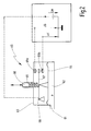
- the structure of the pressure sensor 60 is shown in FIG FIG. 2 shown.
- the pressure sensor 60 Via a pressure input 61, the pressure sensor 60 is fluidically connected to the area in that the pressure to be measured p is present.
- the pressure p Via the pressure input 61, the pressure p is applied in a pressure chamber 62 of the sensor housing 63. Inside the sensor housing 63, the pressure chamber 62 is at a Position limited by a movable sensor membrane 64.
- the sensor membrane 64 is acted upon by a sensor spring 65 on the side opposite the pressure chamber 62.
- the force of the sensor spring 65 presses the sensor membrane 64 against the applied pressure in the pressure chamber 62.
- the spring force of the sensor spring 65 is variable via an adjusting screw 66. Via the force of the sensor spring 65, the desired pressure value p setpoint can be set. If the force of the force of the sensor spring 65 acting on the sensor membrane 64 by the pressure p in the pressure chamber 62 is equal, the sensor diaphragm 64 is in the equilibrium of
- a switching contact 67 is coupled for movement.
- the switching contact 67 is electrically conductive.
- On in a measuring voltage UM is created.
- the switching contact 67 is pivotally mounted at one end via a pivot bearing 68, while its other end between two mating contacts 69a and 69b is arranged.
- the two mating contacts 69a, 69b are arranged in the direction of movement of the sensor membrane 64 with a switching distance.
- the mating contacts 69a, 69b are electrically conductive.
- the second sensor voltage UK is measured.
- the switching contact 67 comes into contact with one of the mating contacts 69a, 69b, the measuring voltage UM is applied to the relevant mating contact 69a, 69b as sensor voltage UG or UK. If the pressure p corresponds to the setpoint pressure, the switching contact 67 in the exemplary embodiment is located between the two mating contacts 69a, 69b. If the pressure in the pressure chamber 62 rises above the desired pressure value p Soll , the switching contact 67 is moved toward the first mating contact 69a. If the pressure p in the pressure chamber 62 drops below the desired pressure value p Soll , the Switching contact 67 to the other, second mating contact 69b.
- the two sensor voltages UG, UK are transmitted to the control device 54 as a sensor signal S.
- the measuring voltage UM for the pressure sensor 60 can be applied via the control device 54, wherein the necessary electrical connection for clarity in the FIGS. 1 and 3 not shown.
- the controller 54 may also be transmitted signals B of the burner 13, which describe the operating state of the burner 13 and / or operating requirements of an operator.
- valves 24, 40 are in their initial state. Both valves 24, 40 are closed and each valve member 26, 27, 42, 43 is sealingly on the associated valve seat 20, 21, 22, 23 at.
- the burner 13 is to be turned on and transmits the power-on request to the control device 54 as signal B. This takes place at the first time t0.
- the control device 54 causes the first valve drive 52 to move the first valve 24 to its maximum open position, so that the opening cross-section Q1 between the first valve member 26 and the first valve seat 20 and the second valve member 27 and the second valve seat 21 assumes the maximum cross-section Q max ,
- the second valve 40 is slowly opened via the second valve drive 53.
- the movement of the second valve lifter 41 may be linear, for example.
- the opening cross section Q2 of the second valve 40 thereby increases steadily from the first time t0.
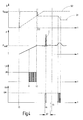
- the pressure sensor 60 measures the pressure p in the outlet channel 17. From the first time t0, the pressure p increases. Since this is still significantly lower than the desired pressure value p desired , the switching contact is applied to the second mating contact 69b, so that the measuring voltage UM is present there as the second sensor voltage UK. With increasing pressure p, the switching contact 67 begins again and again briefly to withdraw from the second mating contact 69b, so that as a second sensor voltage UK from a second time t1 a voltage signal is applied, which is equal to zero and equal to the measuring voltage UM alternately. This is in FIG. 4 schematically represented by the hatched area from the second time t1.
- the pressure p is already so close to the target pressure value p, that the switching contact 67 no longer engages with the second counter-contact 69b to the plant.
- the second sensor voltage UK then remains equal to zero.
- the switching contact 67 has taken a limbo state between the two mating contacts 69 from the third time t2.
- both the first sensor voltage UK, and the second sensor voltage UG is equal to zero.
- the pressure sensor 60 indicates to the control device 54 that the pressure p is within the tolerance range around the desired pressure value p setpoint .
- the opening cross section Q2 at the second valve 40 is further increased. In order to avoid a pressure increase in the outlet channel 17, the opening cross-section Q1 of the first valve 24 is therefore reduced between the third time t2 and a fourth time t3.
- the ignition phase of the burner 13 begins at the first time t0.
- the gas G supplied to the fuel supply line 11 is ignited in a combustion chamber of the burner 13.
- strong pressure fluctuations occur, which can react on the device 10 via the fuel supply line 11.
- a pressure pulse I is caused by the burner 13, which is detected via the pressure sensor 60.
- the first sensor voltage UG rises briefly and assumes the value of the measuring voltage UM. Since the ignition phase of the burner 13 is not yet completed, such pressure pulses I are ignored by the controller 54.
- the first sensor voltage UG which indicates that the pressure p is greater than the desired pressure value p Soll , within a predefinable time window ⁇ T an average value which is smaller than a predetermined threshold, it is concluded that only single pressure pulse I by the Burner 13 were initiated. Such changes in the first sensor voltage UG or the sensor signal S remain disregarded during the ignition phase of the burner 13. As a result of such pressure pulses I, no change in the cross-sectional openings Q1 or Q2 of the two valves 24, 40 is caused.
- the ignition phase of the burner 13 is terminated at a sixth time t5.
- This can be indicated by a burner signal B, for example.
- a lambda sensor can be used, in particular a sensor which measures the ionization current in the combustion chamber.
- the opening cross-section Q1 of the first valve 24 is increased or increased reduced to keep the pressure p in the tolerance range by the predetermined pressure setpoint p setpoint .
- the opening cross-section Q2 of the second valve 40 remains constant at the maximum possible opening cross-section Q max .
- the controller 54 may control the second valve 40 and use it as an adjustable throttle. An additional throttle in the fuel supply line 11 between the gas valve 14 and the burner 13 can then be omitted.
- the pressure p in the first valve channel 18 or in the second valve channel 19 is preferably regulated via the first valve 24.
- the invention relates to a device 10 with a gas valve 14 for influencing the flow rate of a gas G through a fuel supply line 11 to a burner 13.
- the gas valve 14 has a first valve 24 and a second valve 40. Both valves 24, 40 are designed as double-seat valves, each with two valve members 26, 27 and 42, 43.
- Each valve 24, 40 has an electromagnetic valve drive 52, 53. Via a control device 54, the two valve actuators 52, 53 are independently controllable.
- a pressure sensor 60 detects a pressure p downstream of the first valve 24. With the aid of the first valve 24, the control device 54 performs pressure regulation at the pressure measuring point of the pressure sensor 60.
- the second valve 40 connected downstream of the first valve 24 in the direction of flow of the gas G can be used as a throttle. Depending on the required burner output, the volume flow or the mass flow of the gas G through the fuel supply line 11 via the second valve 40 can be adjusted by controlling the valve drive 53 by the control device 54.
Landscapes
- Engineering & Computer Science (AREA)
- Chemical & Material Sciences (AREA)
- Combustion & Propulsion (AREA)
- Mechanical Engineering (AREA)
- General Engineering & Computer Science (AREA)
- Fluid-Driven Valves (AREA)
- Feeding And Controlling Fuel (AREA)
Abstract
Description
- Die vorliegende Erfindung betrifft eine Vorrichtung zur Steuerung der durch eine Brennstoffleitung von einer Brennstoffquelle zu einem Brenner strömenden Brennstoffmenge.
- Eine solche Vorrichtung mit einem druckgesteuerten Doppelabsperrventil ist aus
DE 20 2005 000 346 U1 bekannt. Das Doppelabsperrventil weist ein erstes Ventil und ein zweites Ventil auf. Die beiden Ventile werden durch jeweils eine druckbeaufschlagte Membran gegen die Kraft einer Schließfeder betätigt, wobei der an den Membranen anliegende Steuerdruck über jeweils eine zugeordnete Drucksteuereinheit eingestellt wird, die elektrisch ansteuerbar ist. Die beiden Ventile sind axial fluchtend zueinander angeordnet. - Nachteilig ist bei solchen Vorrichtungen, dass Steuerleitungen zwischen den beiden Ventilen und dem jeweils zugeordneten Drucksteuerelement notwendig sind. Dadurch wird der Aufbau des Gehäuses aufwendig. Andererseits bedarf es einer relativ großen Kraft, um die beiden Ventilabsperrglieder gegen die Schließkraft der Schließfeder zu bewegen, weswegen zur Betätigung der Ventilstößel Membrane mit relativ großer Druckbeaufschlagungsfläche vorgesehen sind.
- Es kann als eine Aufgabe der vorliegenden Erfindung angesehen werden, die bekannte Vorrichtung zu verbessern.
- Diese Aufgabe wird durch eine Vorrichtung mit den Merkmalen des Patentanspruches 1 gelöst.
- Erfindungsgemäß weist die Vorrichtung ein Ventilgehäuse mit einem Eingangskanal und einem Ausgangskanal auf. Innerhalb des Ventilgehäuses ist der Eingangskanal über einen ersten Ventilkanal und einen zweiten Ventilkanal mit dem Ausgangskanal verbunden. Vorzugsweise sind die beiden Ventilkanäle fluidisch parallel geschaltet. Im ersten Ventilkanal ist ein erster Ventilsitz und im zweiten Ventilkanal ein zweiter Ventilsitz vorgesehen. Ein entlang seiner Achse bewegbarer Ventilstößel trägt ein erstes Ventilglied, das dem ersten Ventilsitz zugeordnet ist und ein zweites Ventilglied, das dem zweiten Ventilsitz zugeordnet ist. Der Abstand der beiden Ventilglieder am Ventilstößel entspricht dem Abstand der beiden Ventilsitze, so dass durch eine Schließbewegung des Ventilstößels beide Ventilglieder gleichzeitig schließend am jeweiligen Ventilsitz anliegen können.
- Der über den Eingangskanal an den beiden Ventilgliedern anliegende Druck wirkt in entgegengesetzte Richtungen, das heißt er übt auf das erste Ventilglied eine Kraft in Öffnungsrichtung und auf das zweite Ventilglied eine Kraft in Schließrichtung aus. Vorzugsweise ist die dem Eingangskanal zugeordnete Fläche des zweiten Ventilgliedes größer als die durch den Druck im Eingangskanal beaufschlagte Fläche des ersten Ventilglieds, wenn sich beide Ventilglieder in Schließstellung befinden. Aufgrund des zwei Ventilglieder tragenden Ventilstößels kann das dadurch gebildete Ventil beide Ventilkanäle zum Eingangskanal sicher absperren, ohne dass es hierzu einer zusätzlichen größeren Schließkraft einer Schließfeder bedarf. Eine bei einem bevorzugten Ausführungsbeispiel vorgesehen Schließfeder, die die beiden Ventilglieder in die Schließstellung vorspannt, muss lediglich eine geringe Schließkraft bereitstellen. Dies bringt wiederum den Vorteil mit sich, dass ein dem ersten Ventilstößel zugeordneter erster Ventilantrieb lediglich eine geringe Kraft benötigt, um die beiden Ventilglieder des ersten Ventilstößels in einer Offenstellung zu halten.
- Der erste Ventilantrieb ist elektrisch ansteuerbar. Die zur Einstellung der Offenstellung benötigte elektrische Energie ist wegen der kleinen Gegenkraft durch die Schließfeder gering.
- Die Vorrichtung verfügt außerdem über einen Drucksensor, der den Brennstoffdruck im Ventilkanal und/oder im Ausgangskanal erfasst und abhängig vom erfassten Druck ein elektrisches Sensorsignal erzeugt. Fluidische Ansteuerleitungen im Ventilgehäuse, die zu einem Ventilantrieb oder einem Ventilglied führen, können dadurch entfallen. Die zur Steuerung oder Regelung erforderliche Druckerfassung erfolgt über einen Drucksensor, der ein elektrisches Signal erzeugt und an eine Steuereinrichtung übermittelt. Abhängig von dem elektrischen Sensorsignal wird dann der Ventilantrieb elektrisch angesteuert. Auf diese Weise kann der Druck stromabwärts des Eingangskanals geregelt werden.
- Das Ventilgehäuse weist eine vergleichsweise einfache Struktur auf und kann einen Grundkörper aufweisen, der als Strangpressprofilteil ausgebildet ist. Dieses Strangpressprofilteil wird nach dem Einsetzen eines oder mehrerer Ventilstößel bzw. des Drucksensors durch Abschlussdeckel fluiddicht verschlossen. Die Vorrichtung lässt sich dadurch sehr einfach und kostengünstig herstellen. Durch das Strangpressprofilteil ist eine Lunkerbildung im Ventilgehäuse vermieden, wie sie bei gegossenen Ventilgehäusen auftritt. Solche Lunker können die Stabilität bzw. Dichtheit des Ventilgehäuses beeinträchtigen und sind durch die Verwendung eines Strangpressprofilteils vermieden.
- Bei einer bevorzugten Ausführungsform weist die Vorrichtung einen zweiten Ventilstößel mit einem dritten Ventilglied und einem vierten Ventilglied auf. Der zweite Ventilstößel ist durch einen zweiten, separaten elektrisch ansteuerbaren Ventilantrieb bewegbar. Das dritte Ventilglied ist einem dritten Ventilsitz im ersten Ventilkanal und das vierte Ventilglied einem vierten Ventilsitz im zweiten Ventilkanal zugeordnet. Der erste Ventilstößel, das erste Ventilglied, das zweite Ventilglied und der zugeordnete erste und zweite Ventilsitz sowie der erste Ventilantrieb bilden mithin ein erstes Ventil. Der das dritte Ventilglied und das vierte Ventilglied tragende zweite Ventilstößel, der zugeordnete dritte Ventilsitz, der zugeordnete vierte Ventilsitz und der zweite Ventilantrieb bilden ein zweites Ventil der Vorrichtung. Die beiden Ventile sind über die Steuereinrichtung separat ansteuerbar. Beide Ventilkanäle können mithin durch das erste Ventil und/oder das zweite Ventil abgesperrt werden. Dadurch wird eine hohe Abschaltsicherheit erreicht, insbesondere bei dem Einsatz der Vorrichtung in einer Gasleitung. Die Ventile weisen keine druckbeaufschlagte Membran zur Stößelbetätigung auf. Die Stößelbetätigung erfolgt ausschließlich über elektrisch ansteuerbare Ventilantriebe, die vorzugsweise jeweils einen Elektromagneten und jeweils einen mit dem Stößel verbundenen Magnetanker aufweisen.
- Der Drucksensor ist vorzugsweise dazu eingerichtet, dass als Sensorsignal eine Spannung ausgegeben wird, die anzeigt, ob ein am Drucksensor vorgegebener Drucksollwert überschritten oder unterschritten wird. Eine exakte Bestimmung des herrschenden Drucks anhand des Sensorsignals durch die Steuereinrichtung ist möglich, kann aber bei einem Ausführungsbeispiel entfallen.
- Bei einem bevorzugten Ausführungsbeispiel weist der Drucksensor eine druckbeaufschlagte, gegen die Kraft einer Sensorfeder bewegbare Membran, einen mit dem Membran bewegungsgekoppelten Schaltkontakt und zumindest einen den Schaltkontakt zugeordneten Gegenkontakt auf. Der Schaltkontakt und der Gegenkontakt stellen eine elektrische Verbindung her, wenn sie aneinander anliegen. Die Kraft der Sensorfeder bestimmten den Drucksollwert und kann bei einem Ausführungsbeispiel über eine Einstellschraube manuell oder elektrisch betätigt veränderbar sein. Vorzugsweise sind in Bewegungsrichtung der Membran gesehen auf entgegengesetzte Seiten des Schaltkontakts jeweils ein Gegenkontakt angeordnet. Bei Unterschreitung des Drucksollwerts bewegt sich der Schaltkontakt zu einem Gegenkontakt hin, während bei Überschreiten des Drucksollwerts der Schaltkontakt in Richtung zum anderen Gegenkontakt bewegt wird. Mit Hilfe dieses Drucksensors kann eine hysteresearme Druckregelung erreicht werden. Außerdem ist es möglich, einen eigensicheren Drucksensor aufzubauen. Der Schaltabstand zwischen den beiden Gegenkontakten kann so gewählt werden, dass sich der Schaltkontakt innerhalb des zulässigen Toleranzbereichs um den Drucksollwert immer wieder gegen einen der beiden Gegenkontakte bewegt und die elektrische Verbindung dadurch immer wieder kurzzeitig hergestellt wird. Bei einem solchen Betrieb kann die Funktionssicherheit des Druckssensors erhöht werden.
- Die Steuereinrichtung ist dazu eingerichtet, den Betrieb der Vorrichtung zu steuern. Bei einer bevorzugten Ausführungsform führt die Steuereinrichtung zum Zünden des Brenners folgende Schritte aus:
- Nach der Wärmeanforderung durch den Kessel wird der erste Ventilstößel über den ersten Ventilantrieb abhängig vom Sensorsignal angesteuert, um den Druck gemäß dem vorgegebenen Solldruck einzustellen. Der zweite Ventilstößel wird gleichzeitig ausgehend von der geschlossenen Ventilausgangsstellung über eine vorgegebene Öffnungsbewegung in die vollständig geöffnete Position bewegt. Die Öffnungsbewegung kann beispielsweise eine lineare Bewegung sein. Während dieser Zündphase des Brenners auftretende Druckimpulse bleiben durch die Steuereinrichtung bei einem bevorzugten Ausführungsbeispiel unberücksichtigt. Derartige Druckimpulse während der Zündphase veranlassen keine Änderung der Stellung des ersten Ventilstößels.
- Im Anschluss an die Zündphase kann die Steuereinrichtung den zweiten Ventilantrieb derart ansteuern, dass der zweite Ventilstößel mit dem dritten und vierten Ventilglied als Drosseleinrichtung für den Brenner verwendet wird. Bei dieser Ausgestaltung können Drosseleinrichtungen zwischen dem Ausgangskanal und dem Brenner entfallen.
- Vorteilhafte Ausgestaltungen der erfindungsgemäßen Vorrichtung ergeben sich aus den abhängigen Patentansprüchen und der Beschreibung. In der Beschreibung wird die Erfindung anhand eines bevorzugten Ausführungsbeispiels erläutert. Die Beschreibung beschränkt sich auf wesentliche Merkmale der Erfindung und sonstige Gegebenheiten. Die Zeichnung ist ergänzend heranzuziehen. Es zeigen:
-
Figur 1 ein Blockschaltbild eines Ausführungsbeispiels einer Vorrichtung zur Beeinflussung der Brennstoffmenge in einer Brennstoffzufuhrleitung, -
Figur 2 ein Blockschaltbild eines bevorzugten Ausführungsbeispiels des Drucksensors bei der Vorrichtung nachFigur 1 , -
Figur 3 einen Querschnitt durch das Ventilgehäuse der Vorrichtung nachFigur 1 und -
Figur 4 einen beispielhaften zeitlichen Verlauf, der Position der beiden Ventilstößel, des Drucksignals, sowie des Sensorsignals während und im Anschluss an die Zündphase des Brenners. - In
Figur 1 ist das Blockschaltbild einer Vorrichtung 10 veranschaulicht, die zur Beeinflussung der durch eine Brennstoffleitung 11 fließenden Brennstoffmenge dient. Die Brennstoffleitung 11 führt von einer Brennstoffquelle 12 zu einem Brenner 13. Als Brennstoff dient vorzugsweise Gas. In die Brennstoffleitung 11 ist ein Gasventil 14 der Vorrichtung 10 eingesetzt. Das Gasventil 14 weist ein Ventilgehäuse 15 auf, in dem ein Eingangskanal 16, ein Ausgangskanal 17, ein erster Ventilkanal 18 und ein zweiter Ventilkanal 19 vorhanden sind. Die beiden Ventilkanäle 18, 19 sind fluidisch parallel zueinander geschaltet. Über den Eingangskanal 16 strömt Gas in das Gasventil 14 und über den Ausgangskanal 17 strömt das Gas aus dem Gasventil 14 heraus. - Der erste Ventilkanal 18 mündet an einem ersten Ventilsitz 20 in den Eingangskanal 16 und an einem dritten Ventilsitz 22 in den Ausgangskanal 17. Der zweite Ventilkanal 19 mündet an einem zweiten Ventilsitz 21 in den Eingangskanal 16 und an einem vierten Ventilsitz 23 in den Ausgangskanal 17.
- Am ersten Ventilsitz 20 und am zweiten Ventilsitz 21 ist ein erstes Ventil angeordnet. Das erste Ventil 24 weist einen ersten Ventilstößel 25 auf, der in Bewegungsrichtung R parallel zu seiner Längsachse bewegbar im Ventilgehäuse 15 gelagert ist. Der erste Ventilstößel 25 trägt ein erstes Ventilglied 26, das dem ersten Ventilsitz 20 zugeordnet ist, und mit axialem Abstand hierzu ein zweites Ventilglied 27, das dem zweiten Ventilsitz 21 zugeordnet ist. Die beiden Ventilglieder 26, 27 weisen jeweils ein ringförmiges Dichtelement 28 auf, das in Richtung der Längsachse des Ventilstößels 25 gesehen an der dem jeweiligen Ventilsitz 20, 21 zugeordneten Seiten einen axial vorspringen Dichtvorsprung 29 aufweist und an seiner axial entgegengesetzten Seite durch einen Stützring 30 in Axialrichtung abgestützt ist.
- Die Ventilsitze 20, 21, 22, 23 sind im Ventilgehäuse 15 jeweils durch eine Ringschulter 31 gebildet, die ein zylindrisches Durchgangsloch 32 vollständig umschließt.
- Die Vorrichtung 10 verfügt außerdem über ein zweites Ventil 40, das einen zweiten Ventilstößel 41 aufweist, an dem ein drittes Ventilglied 42 und ein viertes Ventilglied 43 angeordnet sind. Der Aufbau des zweiten Ventils 40 entspricht dem ersten Ventil 24, so dass auf die vorstehende Beschreibung verwiesen werden kann.
- Sind die beiden Ventile 24, 40 geschlossen, so liegt das jeweilige Dichtelement 28 mit seinem Dichtvorsprung 29 am zugeordneten Ventilsitz 20, 21, 22, 23 an. Der erste Ventilstößel 25 durchgreift dabei das jeweilige Durchgangsloch 32 am ersten Ventilsitz 20 und am zweiten Ventilsitz 21. Gleichermaßen durchgreift der zweite Ventilstößel 41 in der geschlossenen Stellung des zweiten Ventils 40 die Durchgangslöcher 32 am dritten Ventilsitz 22 und am vierten Ventilsitz 23.
- Das erste Ventilglied 26 ist im ersten Ventilkanal 18 angeordnet. Das erste Ventilglied 26 liegt bei geschlossenem ersten Ventil 24 auf der dem ersten Ventilkanal 18 zugeordneten Seite des ersten Ventilsitzes 20 an. Das zweite Ventilglied 27 ist im Eingangskanal 16 angeordnet und liegt beispielsgemäß daher bei geschlossenem ersten Ventil 24 auf der dem Eingangskanal 16 zugeordneten Seite des zweiten Ventilsitzes 21 an. Analog hierzu ist das dritte Ventilglied 42 im ersten Ventilkanal 18 angeordnet und das vierte Ventilglied 43 ist im Ausgangskanal 17 angeordnet. Bei geschlossenem zweiten Ventil 40 liegt das zweite Ventilglied 42 an der dem ersten Ventilkanal 18 zugeordneten Seite am dritten Ventilsitz 21 an. In dieser Stellung liegt das vierte Ventilglied 43 an der dem Ausgangskanal 17 zugeordneten Seite des vierten Ventilsitzes 23 an.
- In der Schließstellung des ersten Ventils 24 ist die dem Eingangskanal 16 durch das Durchgangsloch 32 des ersten Ventilsitzes 20 zugewandete erste Fläche A1 kleiner als die dem Eingangskanal 16 zugewandte zweite Fläche A2 des zweiten Ventilgliedes 27. Bei geschlossenem ersten Ventil 24 kann der im Eingangskanal 16 herrschende Druck das erste Ventil 24 nicht öffnen, da die dadurch auf den ersten Ventilstößel 25 ausgeübte resultierende Kraft in Schließrichtung gerichtet ist.
- Eine weitere Erhörung der Sicherheit des Gasventils 14 wird dadurch erreicht, dass die dem ersten Ventilkanal 18 in der Schließstellung des zweiten Ventils 40 zugewandete dritte Fläche A3 des dritten Ventilgliedes 42 größer ist als die dem zweiten Ventilkanal 19 in der Schließstellung des zweiten Ventils 40 zugewandte vierte Fläche A4 des vierten Ventilgliedes 43. Selbst wenn das erste Ventil 24 aufgrund einer Fehlfunktion nicht schließen kann und der am Eingangskanal 16 herrschende Druck über den ersten Ventilkanal 18 und dem zweiten Ventilkanal 19 am zweiten Ventil 40 anliegt, bleibt das zweite Ventil 40 in seiner Schließstellung, weil die durch den anstehenden Druck resultierende Kraft auf den zweiten Ventilstößel 41 in Schließrichtung ausgeübt wird.
- Das in
Figur 3 dargestellte Ventilgehäuse 15 enthält einen Grundkörper 46, der als Strangpressprofilteil ausgeführt ist. Der Grundkörper 46 weist im Bereich der beiden Ventilkanäle 18, 19 nach außen offene Ausnehmungen 56 aus, die zur Bildung der Ventilkanäle 18, 19 durch jeweils einen Deckel 47, 48 fluiddicht und beispielsgemäß gasdicht verschlossen sind. Die beiden Ventilstößel 25, 41 sind gasdicht durch den dem ersten Ventilkanal 18 zugeordneten Deckel 47 herausgeführt. - Die Ausnehmungen 56 zur Bildung der beiden Ventilkanäle 18, 19 sind zu entgegengesetzten Seiten des Grundkörpers 46 hin offen, vorzugsweise entlang der gesamten Länge der Ventilkanäle 18, 19 in Längsrichtung L des Gasventils 14. Die Durchgangslöcher 32 des ersten Ventilsitzes 20 und des dritten Ventilsitzes 22 sind in einer der Öffnung der Ausnehmung 56 entgegengesetzten Innenwand 57 angeordnet. Die Innenwand 57 verläuft parallel zu einer Längsachse L des Gasventils 14. Analog gilt dies auch für den zweiten Ventilkanal 19, in dessen vorzugsweise parallel zur Längsrichtung L verlaufender Innenwand 57 die Durchgangslöcher 32 des zweiten Ventilsitzes 21 und des vierten Ventilsitzes 23 angeordnet sind. Die Mündung 16a des Eingangskanals 16 und/oder die Mündung 17a des Ausgangskanals 17 am Grundkörper 46 sind beispielsgemäß koaxial zur Längsachse L angeordnet. Eine zentrale Wand 58 sperrt die direkte fluidisch Verbindung zwischen dem Eingangskanal 16 und dem Ausgangskanal 17 Die Längsachse L verläuft durch die zentrale Wand 58. Letztere befindet sich in Richtung der Längsachse L gesehen zwischen dem ersten Ventilsitz 20 und dem dritten Ventilsitz 22 sowie zwischen dem zweiten Ventilsitz 21 und dem vierten Ventilsitz 23.
- Außerhalb des Ventilgehäuses 15 ist jeweils ein Magnetanker 50 mit dem freien Ende des Ventilstößels 25 und des Ventilstößels 41 verbunden. Jeder Magnetanker 50 ist von einem Elektromagneten 51 koaxial umschlossen. Der Magnetanker 50 und der zugeordnete Elektromagnet 51 bilden für das erste Ventil 24 einen ersten Ventilantrieb 52 und für das zweite Ventil 40 einen zweiten Ventilantrieb 53. Die beiden Ventilantriebe 52, 53 sind elektrisch über eine Steuereinrichtung 54 angesteuert. Über die Ventilantriebe 52, 53 können die Ventilglieder 26, 27 bzw. 42, 43 gegen die Schließkraft einer Schließfeder 55 bewegt werden. Beim Ausführungsbeispiel ist jedem Ventil 24, 40 eine Schließfeder 55 zugeordnet, die die jeweiligen Ventilglieder 26, 27 bzw. 42, 43 mit einer Schließkraft zum zugeordneten Ventilsitz 20, 21 bzw. 22, 23 hin beaufschlagt. Die Schließfedern 55 können wie schematisch in
Figur 1 dargestellt im ersten Ventilkanal 18 angeordnet sein und das erste Ventilglied 26 bzw. das dritte Ventilglied 42 beaufschlagen. Alternativ hierzu könnten die Schließfedern 55 auch auf das jeweils andere Ventilglied 27 bzw. 43 einwirken und im Eingangskanal 16 bzw. im Ausgangskanal 17 angeordnet sein. Jedes Ventil 24, 40 könnte auch mehr als eine Schließfeder 55 aufweisen. - Der Steuereinrichtung 54 wird ein Sensorsignal S eines Drucksensors 60 der Vorrichtung 10 zugeführt. Die Vorrichtung 10 weist zumindest einen Drucksensor 60 auf. Der Drucksensor 60 erfasst den Druck p im ersten Ventilkanal 18 oder im zweiten Ventilkanal 19 oder im Ausgangskanal 17. Zur Erfassung des Drucks p im Ausgangskanal 17 kann der Drucksensor 60 auch unmittelbar im Anschluss an den Ausgangskanal 17 in die Brennstoffzufuhrleitung 11 eingesetzt sein. Es ist auch möglich, den Druck p an mehreren der angegebenen Stellen zu erfassen und mithin mehrere Drucksensoren 60 anzuordnen wie dies in
Figur 1 gestrichelt durch einen weiteren Drucksensor 60 veranschaulicht ist. - Der Aufbau des Drucksensors 60 ist in
Figur 2 dargestellt. Über einen Druckeingang 61 ist der Drucksensor 60 fluidisch mit dem Bereich verbunden, indem der zu messende Druck p anliegt. Über den Druckeingang 61 liegt der Druck p in einer Druckkammer 62 des Sensorgehäuses 63 an. Im Inneren des Sensorgehäuses 63 ist die Druckkammer 62 an einer Stelle durch eine bewegliche Sensormembran 64 begrenzt. Die Sensormembran 64 ist auf der der Druckkammer 62 entgegengesetzten Seite mit einer Kraft von einer Sensorfeder 65 beaufschlagt. Die Kraft der Sensorfeder 65 drückt die Sensormembran 64 gegen den in der Druckkammer 62 anliegenden Druck. Die Federkraft der Sensorfeder 65 ist über eine Einstellschraube 66 variierbar. Über die Kraft der Sensorfeder 65 kann der Drucksollwert pSoll eingestellt werden. Entspricht die durch den Druck p in der Druckkammer 62 auf die Sensormembran 64 einwirkende Kraft der Kraft der Sensorfeder 65, so befindet sich die Sensormembran 64 im Kräftegleichgewicht. Die Sensormembran 64 bewegt sich bei einer Druckänderung in die entsprechende Richtung. - Mit der Sensormembran 64 ist ein Schaltkontakt 67 bewegungsgekoppelt. Der Schaltkontakt 67 ist elektrisch leitend. An in ist eine Messspannung UM angelegt. Beim Ausführungsbeispiel ist der Schaltkontakt 67 an einem Ende über eine Schwenklagerung 68 schwenkbar gelagert, während sein anderes Ende zwischen zwei Gegenkontakten 69a und 69b angeordnet ist. Die beiden Gegenkontakte 69a, 69b sind in Bewegungsrichtung der Sensormembran 64 gesehen mit Schaltabstand angeordnet. Die Gegenkontakte 69a, 69b sind elektrisch leitfähig. Am ersten Gegenkontakt 69a wird die erste Sensorspannung UG und am zweiten Gegenkontakt 69b wird die zweite Sensorspannung UK gemessen. Gelangt der Schaltkontakt 67 mit einem der Gegenkontakte 69a, 69b zur Anlage, liegt am betreffenden Gegenkontakt 69a, 69b als Sensorspannung UG oder UK die Messspannung UM an. Entspricht der Druck p dem Solldruck befindet sich der Schaltkontakt 67 beim Ausführungsbeispiel zwischen den beiden Gegenkontakten 69a, 69b. Steigt der Druck in der Druckkammer 62 über den Drucksollwert pSoll an, wird der Schaltkontakt 67 zum ersten Gegenkontakt 69a hinbewegt. Sinkt der Druck p in der Druckkammer 62 unter den Drucksollwert pSoll, bewegt sich der Schaltkontakt 67 zum jeweils anderen, zweiten Gegenkontakt 69b.
- Die beiden Sensorspannungen UG, UK werden der Steuereinrichtung 54 als Sensorsignal S übermittelt. Die Messspannung UM für den Drucksensor 60 kann über die Steuereinrichtung 54 angelegt werden, wobei die für notwendige elektrische Verbindung der Übersichtlichkeit halber in den
Figuren 1 und3 nicht gezeigt ist. - Der Steuereinrichtung 54 können außerdem Signale B des Brenners 13 übermittelt werden, die den Betriebszustand des Brenners 13 und/oder Bedienanforderungen einer Bedienperson beschreiben.
- Insbesondere anhand von
Figur 4 soll der durch die Steuereinrichtung 54 veranlasste Betrieb der Vorrichtung 10 näher erläutert werden. - Es sei angenommen, dass sich die beiden Ventile 24, 40 in ihrem Ausgangszustand befinden. Beide Ventile 24, 40 sind geschlossen und jedes Ventilglied 26, 27, 42, 43 liegt dichtend am zugeordneten Ventilsitz 20, 21, 22, 23 an. Der Brenner 13 soll eingeschaltet werden und übermittelt als Signal B die Einschaltanforderung an die Steuereinrichtung 54. Dies erfolgt zum ersten Zeitpunkt t0. Die Steuereinrichtung 54 veranlasst den ersten Ventilantrieb 52 das erste Ventil 24 in seine maximale Offenstellung zu bewegen, so dass der Öffnungsquerschnitt Q1 zwischen dem ersten Ventilglied 26 und dem ersten Ventilsitz 20 sowie dem zweiten Ventilglied 27 und dem zweiten Ventilsitz 21 den maximalen Querschnitt Qmax annimmt.
- Das zweite Ventil 40 wird über den zweiten Ventilantrieb 53 langsam geöffnet. Die Bewegung des zweiten Ventilstößels 41 kann beispielsweise linear erfolgen. Der Öffnungsquerschnitt Q2 des zweiten Ventils 40 nimmt dadurch ab dem ersten Zeitpunkt t0 stetig zu.
- Der Drucksensor 60 misst den Druck p im Ausgangskanal 17. Ab dem ersten Zeitpunkt t0 steigt der Druck p an. Da dieser noch deutlich geringer ist als der Drucksollwert pSoll liegt der Schaltkontakt am zweiten Gegenkontakt 69b an, so dass dort als zweite Sensorspannung UK die Messspannung UM anliegt. Mit zunehmendem Druck p beginnt sich der Schaltkontakt 67 immer wieder kurzzeitig vom zweiten Gegenkontakt 69b abzuheben, so dass als zweite Sensorspannung UK ab einem zweiten Zeitpunkt t1 ein Spannungssignal anliegt, das abwechselnd gleich null und gleich der Messspannung UM ist. Dies ist in
Figur 4 schematisch durch die schraffierte Fläche ab dem zweiten Zeitpunkt t1 dargestellt. Ab einem dritten Zeitpunkt t2 ist der Druck p bereits so nahe am Drucksollwert pSoll, dass der Schaltkontakt 67 nicht mehr mit dem zweiten Gegenkontakt 69b zur Anlage gelangt. Die zweite Sensorspannung UK bleibt dann gleich null. Der Schaltkontakt 67 hat ab dem dritten Zeitpunkt t2 einen Schwebezustand zwischen den beiden Gegenkontakten 69 eingenommen. - Ab dem dritten Zeitpunkt t2 ist sowohl die erste Sensorspannung UK, als auch die zweite Sensorspannung UG gleich null. Der Drucksensor 60 zeigt der Steuereinrichtung 54 damit an, dass sich der Druck p im Toleranzbereich um den Drucksollwert pSoll befindet. Zum dritten Zeitpunkt t2 wird der Öffnungsquerschnitt Q2 am zweiten Ventil 40 weiter erhöht. Um eine Druckerhöhung im Ausgangskanal 17 zu vermeiden, wird der Öffnungsquerschnitt Q1 des ersten Ventils 24 daher zwischen dem dritten Zeitpunkt t2 und einem vierten Zeitpunkt t3 verringert.
- Mit dem ersten Zeitpunkt t0 beginnt die Zündphase des Brenners 13. Dabei wird das für die Brennstoffzufuhrleitung 11 zugeführte Gas G in einer Brennkammer des Brenners 13 entzündet. Beim Zünden der Flamme entstehen starke Druckschwankungen, die über die Brennstoffzufuhrleitung 11 auf die Vorrichtung 10 zurückwirken können. Zu einem fünften Zeitpunkt t4 ist bei dem hier beschriebenen beispielhaften Verlauf ein Druckimpuls I durch den Brenner 13 verursacht, der über den Drucksensor 60 erfasst wird. Zu diesem fünften Zeitpunkt t4 steigt die erste Sensorspannung UG kurzzeitig an und nimmt den Wert der Messspannung UM ein. Da die Zündphase des Brenners 13 noch nicht abgeschlossen ist, werden derartige Druckimpulse I durch die Steuereinrichtung 54 ignoriert. Nimmt die erste Sensorspannung UG, die anzeigt, dass der Druck p größer ist als der Drucksollwert pSoll, in einem vorgebbaren Zeitfenster ΔT einen Mittelwert an, der kleiner ist als ein vorgegebenen Schwellenwert, so wird daraus geschlossen, dass nur einzelne Druckimpuls I durch den Brenner 13 veranlasst wurden. Derartige Veränderungen der ersten Sensorspannung UG bzw. des Sensorsignals S bleiben während der Zündphase des Brenners 13 unberücksichtigt. Durch solche Druckimpulse I wird mithin keine Änderung der Querschnittsöffnungen Q1 oder Q2 der beiden Ventile 24, 40 veranlasst.
- Beim Ausführungsbeispiel ist angenommen, dass die Zündphase des Brenners 13 zu einem sechsten Zeitpunkt t5 beendet ist. Dies kann beispielsweise durch ein Brennersignal B angezeigt werden. Hierfür kann beispielsweise ein Lambdasensor verwendet werden, insbesondere ein Sensor, der den Ionisationsstrom in der Brennkammer misst.
- Verändert sich nach dem Ende der Zündphase, also ab dem sechsten Zeitpunkt t5 der Druck p, so wird der Öffnungsquerschnitt Q1 des ersten Ventils 24 vergrößert oder verkleinert, um den Druck p im Toleranzbereich um den vorgegebenen Drucksollwert pSoll zu halten.
- Bei dem hier in
Figur 4 dargestellten Ausführungsbeispiel bleibt der Öffnungsquerschnitt Q2 des zweiten Ventils 40 konstant beim maximal möglichen Öffnungsquerschnitt Qmax. Alternativ hierzu kann die Steuereinrichtung 54 das zweite Ventil 40 ansteuern und als verstellbare Drossel verwenden. Eine zusätzliche Drosselklappe in der Brennstoffzufuhrleitung 11 zwischen dem Gasventil 14 und dem Brenner 13 kann dann entfallen. Über das erste Ventil 24 wird bei dieser Ausgestaltung vorzugsweise der Druck p im ersten Ventilkanal 18 bzw. im zweiten Ventilkanal 19 geregelt. - Die Erfindung betrifft eine Vorrichtung 10 mit einem Gasventil 14 zur Beeinflussung der Durchflussmenge eines Gases G durch eine Brennstoffzufuhrleitung 11 zu einem Brenner 13. Das Gasventil 14 weist ein erstes Ventil 24 und ein zweites Ventil 40 auf. Beide Ventile 24, 40 sind als Doppelsitzventile mit jeweils zwei Ventilgliedern 26, 27 bzw. 42, 43 ausgestaltet. Jedes Ventil 24, 40 weist einen elektromagnetischen Ventilantrieb 52, 53 auf. Über eine Steuereinrichtung 54 sind die beiden Ventilantriebe 52, 53 unabhängig voneinander ansteuerbar. Ein Drucksensor 60 erfasst einen Druck p stromabwärts des ersten Ventils 24. Mit Hilfe des ersten Ventils 24 führt die Steuereinrichtung 54 eine Druckregelung an der Druckmessstelle des Drucksensors 60 durch. Das dem ersten Ventil 24 in Strömungsrichtung des Gases G nachgeschaltete zweite Ventil 40 kann als Drossel verwendet werden. Abhängig von der angeforderten Brennerleistung kann der Volumenstrom oder der Massenstrom des Gases G durch die Brennstoffzufuhrleitung 11 über das zweite Ventil 40 durch Ansteuerung des Ventilantriebs 53 durch die Steuereinrichtung 54 eingestellt werden.
-
- 10
- Vorrichtung
- 11
- Brennstoffleitung
- 12
- Brennstoffquelle
- 13
- Brenner
- 14
- Gasventil
- 15
- Ventilgehäuse
- 16
- Eingangskanal
- 17
- Ausgangskanal
- 18
- erster Ventilkanal
- 19
- zweiter Ventilkanal
- 20
- erster Ventilsitz
- 21
- zweiter Ventilsitz
- 22
- dritter Ventilsitz
- 23
- vierter Ventilsitz
- 24
- erstes Ventil
- 25
- erster Ventilstößel
- 26
- erstes Ventilglied
- 27
- zweites Ventilglied
- 28
- Dichtelement
- 29
- Dichtvorsprung
- 30
- Stützring
- 31
- Ringschulter
- 32
- Durchgangsloch
- 40
- zweites Ventil
- 41
- zweiter Ventilstößel
- 42
- drittes Ventilglied
- 43
- viertes Ventilglied
- 46
- Grundkörper
- 47
- Deckel
- 48
- Deckel
- 50
- Magnetanker
- 51
- Elektromagnet
- 52
- erster Ventilantrieb
- 53
- zweiter Ventilantrieb
- 54
- Steuereinrichtung
- 55
- Schließfeder
- 56
- Ausnehmung
- 57
- Innenwand
- 58
- zentrale Wand
- 60
- Drucksensor
- 61
- Druckeingang
- 62
- Druckkammer
- 63
- Sensorgehäuse
- 64
- Sensormembran
- 65
- Sensorfeder
- 66
- Einstellschraube
- 67
- Schaltkontakt
- 68
- Schwenklagerung
- 69a
- erster Gegenkontakt
- 69b
- zweiter Gegenkontakt
- A1
- erste Fläche
- A2
- zweite Fläche
- A3
- dritte Fläche
- A4
- vierte Fläche
- B
- Signal des Brenners
- I
- Druckimpuls
- L
- Längsachse
- p
- Druck
- Psoll
- Drucksollwert
- Q1
- Öffnungsquerschnitt des ersten Ventils
- Q2
- Öffnungsquerschnitt des zweiten Ventils
- Qmax
- maximaler Öffnungsquerschnitt
- R
- Bewegungsrichtung
- S
- Sensorsignal
- t
- Zeit
- t1...t5
- Zeitpunkt
- ΔT
- Zeitfenster
- UG
- erste Sensorspannung
- UK
- zweite Sensorspannung
- UM
- Messspannung
Claims (15)
- Vorrichtung (10) zur Steuerung der durch eine Brennstoffleitung (11) strömenden Brennstoffmenge (G),
mit einem Ventilgehäuse (15) das einen Eingangskanal (16), einem Ausgangskanal (17), einen ersten Ventilkanal (18) und einem zweiten Ventilkanal (19) aufweist, wobei die beiden Ventilkanäle (18, 19) den Eingangskanal (16) mit dem Ausgangskanal (17) fluidisch verbinden,
mit einem ersten Ventilsitz (20) im ersten Ventilkanal (18) und mit einem zweiten Ventilsitz (21) im zweiten Ventilkanal (19),
mit einem Ventilstößel (25), der ein dem ersten Ventilsitz (20) zugeordnetes erstes Ventilglied (26) und ein dem zweiten Ventilsitz (21) zugeordnetes zweites Ventilglied (27) trägt,
mit einem elektrisch ansteuerbaren Ventilantrieb (52) zur Bewegung des Ventilstößels (25),
mit einem Drucksensor (60), der abhängig von dem Druck (p) in einem Ventilkanal (18, 19) und/oder im Ausgangskanal (17) ein elektrisches Sensorsignal (S) erzeugt,
mit einer Steuereinrichtung (54), die den Ventilantrieb (52) abhängig vom Sensorsignal (S) ansteuert. - Vorrichtung nach Anspruch 1,
dadurch gekennzeichnet, dass der Drucksensor (60) nur anzeigt, ob der Druck (p) größer oder kleiner als ein vorgegebener Drucksollwert (psoll) ist. - Vorrichtung nach Anspruch 1,
dadurch gekennzeichnet, dass der Drucksensor (60) eine druckbeaufschlagte, gegen die Kraft einer Sensorfeder (65) bewegbare Sensormembran (64), einen mit der Sensormembran (64) bewegungsgekoppelten Schaltkontakt (67) und zumindest einen dem Schaltkontakt (67) zugeordneten Gegenkontakt (69a, 69b) aufweist, wobei der Schaltkontakt (67) und der Gegenkontakt (69a, 69b) eine elektrische Verbindung herstellen, wenn der Schaltkontakt (67) am Gegenkontakt (69a, 69b) anliegt. - Vorrichtung nach Anspruch 2 und 3,
dadurch gekennzeichnet, dass der Drucksollwert (psoll) durch die auf die Sensormembran (64) einwirkende und durch die Sensorfeder (65) vorgegebene Kraft einstellbar oder vorgebbar ist. - Vorrichtung nach Anspruch 3,
dadurch gekennzeichnet, dass der Drucksensor (60) zwei Gegenkontakte (69a, 69b) aufweist, die in Bewegungsrichtung der Sensormembran (64) auf entgegengesetzten Seiten des Schaltkontakts (67) angeordnet sind. - Vorrichtung nach Anspruch 3,
dadurch gekennzeichnet, dass an den Schaltkontakt (67) eine Messspannung (UM) angelegt ist und die Steuereinrichtung (54) die am Gegenkontakt (69a, 69b) anliegende Sensorspannung (UG, UK) zur Beurteilung des an der Sensormembran (64) anliegenden Drucks (p) auswertet. - Vorrichtung nach Anspruch 1,
dadurch gekennzeichnet, dass das erste Ventilglied (26) und das zweite Ventilglied (27) durch eine Schließkraft einer Schließfeder (55) beaufschlagt sind, wobei die Schließkraft zum jeweiligen Ventilsitz (20, 21) hin gerichtet ist. - Vorrichtung nach Anspruch 1,
dadurch gekennzeichnet, dass im ersten Ventilkanal (18) ein dritter Ventilsitz (22) und im zweiten Ventilkanal () ein vierter Ventilsitz (23) angeordnet ist. - Vorrichtung nach Anspruch 8,
dadurch gekennzeichnet, dass ein weiterer, zweiter Ventilstößel (41) vorhanden ist, der ein dem dritten Ventilsitz (22) zugeordnetes drittes Ventilglied (42) und ein dem vierten Ventilsitz (23) zugeordnetes viertes Ventilglied (43) trägt und der durch einen elektrisch ansteuerbaren zweiten Ventilantrieb (53) bewegbar ist. - Vorrichtung nach Anspruch 9,
dadurch gekennzeichnet, dass das dritte Ventilglied (42) und das vierte Ventilglied (43) durch eine Schließkraft einer Schließfeder (55) beaufschlagt sind, wobei die Schließkraft zum jeweiligen Ventilsitz (22, 23) hin gerichtet ist. - Vorrichtung nach Anspruch 9,
dadurch gekennzeichnet, dass die Steuereinrichtung (54) dazu eingerichtet ist, die Brennstoffmenge (G) durch die Brennstoffleitung (11) zu einem Brenner (13) während dessen Zündphase mit folgenden Schritten zu steuern:- Ansteuern des den ersten Ventilstößel (25) betätigenden ersten Ventilantriebs (52) abhängig vom Sensorsignal (S) zur Einstellung des Drucks (p) am Drucksensor (60) gemäß dem vorgegebenen Solldruck (psoll),- Ansteuern des den zweiten Ventilstößel (41) betätigenden zweiten Ventilantriebs (53) zum Bewegen des dritten Ventilgliedes (42) und des vierten Ventilgliedes (43) aus einer den Öffnungsquerschnitt (Q2) an den zugeordneten Ventilsitzen (22, 23) vollständig schlie-βenden Ausgangsstellung in eine den maximal möglichen Öffnungsquerschnitt (Qmax) einstellende Endstellung. - Vorrichtung nach Anspruch 11,
dadurch gekennzeichnet, dass die Steuereinrichtung (54) dazu eingerichtet ist, während der Zündphase des Brenners (13) in der Brennstoffleitung (11) auftretende Druckimpulse (I) zu erkennen, wobei die Ansteuerung des ersten Ventilantriebs (52) durch die Druckimpulse (I) unverändert bleibt. - Vorrichtung nach Anspruch 11,
dadurch gekennzeichnet, dass die Steuereinrichtung (54) dazu eingerichtet ist, den zweiten Ventilantrieb (53) anzusteuern, um den zweiten Ventilstößel (41) mit dem dritten Ventilglied (42) und vierten Ventilglied (43) und die zugeordneten Ventilsitze (22, 23) als Drosseleinrichtung zu verwenden. - Vorrichtung nach Anspruch 1,
dadurch gekennzeichnet, dass die beiden Ventilkanäle (18, 19) fluidisch parallel geschaltet sind. - Vorrichtung nach Anspruch 1,
dadurch gekennzeichnet, dass das Ventilgehäuse (14) ein Strangpressprofilteil (16) aufweist, in dem die Ventilsitze (20, 21, 22, 23) angeordnet sind.
Applications Claiming Priority (1)
| Application Number | Priority Date | Filing Date | Title |
|---|---|---|---|
| DE102011053152A DE102011053152A1 (de) | 2011-08-31 | 2011-08-31 | Vorrichtung zur Steuerung der Brennstoffmenge durch eine Brennstoffleitung |
Publications (3)
| Publication Number | Publication Date |
|---|---|
| EP2565540A2 true EP2565540A2 (de) | 2013-03-06 |
| EP2565540A3 EP2565540A3 (de) | 2013-04-17 |
| EP2565540B1 EP2565540B1 (de) | 2014-09-10 |
Family
ID=46581771
Family Applications (1)
| Application Number | Title | Priority Date | Filing Date |
|---|---|---|---|
| EP12176380.9A Not-in-force EP2565540B1 (de) | 2011-08-31 | 2012-07-13 | Vorrichtung zur Steuerung der Brennstoffmenge durch eine Brennstoffleitung |
Country Status (2)
| Country | Link |
|---|---|
| EP (1) | EP2565540B1 (de) |
| DE (1) | DE102011053152A1 (de) |
Cited By (2)
| Publication number | Priority date | Publication date | Assignee | Title |
|---|---|---|---|---|
| CN111075984A (zh) * | 2020-01-14 | 2020-04-28 | 嘉兴市大宇机电有限公司 | 一种校零空燃比例电磁阀 |
| CN115479136A (zh) * | 2021-06-14 | 2022-12-16 | 西门子股份公司 | 阀组件 |
Families Citing this family (1)
| Publication number | Priority date | Publication date | Assignee | Title |
|---|---|---|---|---|
| US11835409B2 (en) | 2020-12-26 | 2023-12-05 | Honeywell International Inc. | Pressure monitoring using a hybrid pressure switch |
Citations (1)
| Publication number | Priority date | Publication date | Assignee | Title |
|---|---|---|---|---|
| DE202005000346U1 (de) | 2005-01-11 | 2005-05-12 | Huang, Chun-Cheng | Druckgesteuertes Doppelabsperrventil |
Family Cites Families (4)
| Publication number | Priority date | Publication date | Assignee | Title |
|---|---|---|---|---|
| DE3942437C3 (de) * | 1989-12-22 | 1994-04-07 | Dungs Karl Gmbh & Co | Gasarmatur |
| DE4337703C1 (de) * | 1993-11-05 | 1995-03-23 | Dungs Karl Gmbh & Co | Mehrfachstellgerät mit eingangsseitigem Regler |
| US6330880B1 (en) * | 1998-02-27 | 2001-12-18 | Mitsubishi Denki Kabushiki Kaisha | Exhaust gas recirculation system |
| DE10114249A1 (de) * | 2001-03-22 | 2002-09-26 | Siemens Building Tech Ag | Doppelventil |
-
2011
- 2011-08-31 DE DE102011053152A patent/DE102011053152A1/de not_active Withdrawn
-
2012
- 2012-07-13 EP EP12176380.9A patent/EP2565540B1/de not_active Not-in-force
Patent Citations (1)
| Publication number | Priority date | Publication date | Assignee | Title |
|---|---|---|---|---|
| DE202005000346U1 (de) | 2005-01-11 | 2005-05-12 | Huang, Chun-Cheng | Druckgesteuertes Doppelabsperrventil |
Cited By (6)
| Publication number | Priority date | Publication date | Assignee | Title |
|---|---|---|---|---|
| CN111075984A (zh) * | 2020-01-14 | 2020-04-28 | 嘉兴市大宇机电有限公司 | 一种校零空燃比例电磁阀 |
| CN111075984B (zh) * | 2020-01-14 | 2022-02-22 | 嘉兴市大宇机电有限公司 | 一种校零空燃比例电磁阀 |
| CN115479136A (zh) * | 2021-06-14 | 2022-12-16 | 西门子股份公司 | 阀组件 |
| EP4105555A1 (de) * | 2021-06-14 | 2022-12-21 | Siemens Aktiengesellschaft | Gasventilanordnung |
| US11867296B2 (en) | 2021-06-14 | 2024-01-09 | Siemens Aktiengesellschaft | Valve assembly |
| CN115479136B (zh) * | 2021-06-14 | 2025-09-23 | 西门子股份公司 | 阀组件 |
Also Published As
| Publication number | Publication date |
|---|---|
| DE102011053152A1 (de) | 2013-02-28 |
| EP2565540A3 (de) | 2013-04-17 |
| EP2565540B1 (de) | 2014-09-10 |
Similar Documents
| Publication | Publication Date | Title |
|---|---|---|
| DE19515286C2 (de) | Druckregler zum Erzeugen eines geregelten Steuerdrucks für ein membrangesteuertes Gasventil | |
| EP0757200B1 (de) | Doppel-Sicherheitsmagnetventil | |
| EP2921924B1 (de) | Vorrichtung zur Bereitstellung eines Fluids mit geregeltem Ausgangsdruck | |
| DE102011101187A1 (de) | Druckminderer | |
| EP2237128A1 (de) | Vorgesteuerte Druckproportionalventilanordnung mit einer durch eine elektronische Regelungseinrichtung angesteuerten Vorsteuerstufe | |
| EP2565540B1 (de) | Vorrichtung zur Steuerung der Brennstoffmenge durch eine Brennstoffleitung | |
| EP1032375A1 (de) | Hydraulisches wegeventil | |
| EP3087279B1 (de) | Ventilanordnung | |
| EP0955472B1 (de) | Sitzventil | |
| EP1979796B1 (de) | Ventilanordnung zum anschliessen eines wärmetauschers einer warmwasserentnahmevorrichtung an ein fernwärmenetz | |
| DE4019757A1 (de) | Membrangesteuerter gasdruckregler | |
| EP1970787B1 (de) | Druckregel-Sitzventil | |
| EP2642132A2 (de) | Hydraulische Pilotventilanordnung und hydraulische Ventilanordnung damit | |
| EP1870621B1 (de) | Ventil zur Steuerung eines Fluids | |
| EP1278011A2 (de) | Ventileinsatz und Ventil für Gasgeräte | |
| EP2452078B1 (de) | Anordnung zur bereitstellung eines veränderbaren drosselquerschnitts für einen fluidstrom | |
| EP3563076B1 (de) | Elektromagnetische klappanker-ventilvorrichtung | |
| DE10006600B4 (de) | Gasventil und Verfahren zum Betrieb eines Gasventils | |
| EP1146268A2 (de) | Betätigungsvorrichtung für ein Ventilglied eines Ventils sowie ein derartiges Ventil | |
| DE102012223244A1 (de) | Kraftstoffeinspritzventil für Brennkraftmaschinen | |
| EP1650427B1 (de) | Kraftstoffeinspritzventil für Brennkraftmaschinen | |
| EP0109978A1 (de) | Gasregelgerät mit Servodruckregler | |
| EP4067745B1 (de) | Verfahren und anordnung zur beeinflussung eines volumenstromes durch einen strömungsweg für brenngas zu einem heizgerät | |
| DE102006004179B4 (de) | Ventilanordnung zum Anschließen eines Wärmetauschers einer Warmwasserentnahmevorrichtung an ein Fernwärmenetz | |
| WO2002086996A1 (de) | Brennstoffzellensystem und verfahren zur druckregulation in brennstoffzellensystemen |
Legal Events
| Date | Code | Title | Description |
|---|---|---|---|
| PUAI | Public reference made under article 153(3) epc to a published international application that has entered the european phase |
Free format text: ORIGINAL CODE: 0009012 |
|
| AK | Designated contracting states |
Kind code of ref document: A2 Designated state(s): AL AT BE BG CH CY CZ DE DK EE ES FI FR GB GR HR HU IE IS IT LI LT LU LV MC MK MT NL NO PL PT RO RS SE SI SK SM TR |
|
| AX | Request for extension of the european patent |
Extension state: BA ME |
|
| PUAL | Search report despatched |
Free format text: ORIGINAL CODE: 0009013 |
|
| AK | Designated contracting states |
Kind code of ref document: A3 Designated state(s): AL AT BE BG CH CY CZ DE DK EE ES FI FR GB GR HR HU IE IS IT LI LT LU LV MC MK MT NL NO PL PT RO RS SE SI SK SM TR |
|
| AX | Request for extension of the european patent |
Extension state: BA ME |
|
| RIC1 | Information provided on ipc code assigned before grant |
Ipc: F23N 1/00 20060101AFI20130314BHEP |
|
| 17P | Request for examination filed |
Effective date: 20130924 |
|
| RBV | Designated contracting states (corrected) |
Designated state(s): AL AT BE BG CH CY CZ DE DK EE ES FI FR GB GR HR HU IE IS IT LI LT LU LV MC MK MT NL NO PL PT RO RS SE SI SK SM TR |
|
| GRAP | Despatch of communication of intention to grant a patent |
Free format text: ORIGINAL CODE: EPIDOSNIGR1 |
|
| INTG | Intention to grant announced |
Effective date: 20140611 |
|
| GRAS | Grant fee paid |
Free format text: ORIGINAL CODE: EPIDOSNIGR3 |
|
| GRAA | (expected) grant |
Free format text: ORIGINAL CODE: 0009210 |
|
| AK | Designated contracting states |
Kind code of ref document: B1 Designated state(s): AL AT BE BG CH CY CZ DE DK EE ES FI FR GB GR HR HU IE IS IT LI LT LU LV MC MK MT NL NO PL PT RO RS SE SI SK SM TR |
|
| REG | Reference to a national code |
Ref country code: GB Ref legal event code: FG4D Free format text: NOT ENGLISH |
|
| REG | Reference to a national code |
Ref country code: CH Ref legal event code: EP |
|
| REG | Reference to a national code |
Ref country code: IE Ref legal event code: FG4D Free format text: LANGUAGE OF EP DOCUMENT: GERMAN |
|
| REG | Reference to a national code |
Ref country code: AT Ref legal event code: REF Ref document number: 686891 Country of ref document: AT Kind code of ref document: T Effective date: 20141015 |
|
| REG | Reference to a national code |
Ref country code: DE Ref legal event code: R096 Ref document number: 502012001232 Country of ref document: DE Effective date: 20141023 |
|
| REG | Reference to a national code |
Ref country code: NL Ref legal event code: T3 |
|
| PG25 | Lapsed in a contracting state [announced via postgrant information from national office to epo] |
Ref country code: NO Free format text: LAPSE BECAUSE OF FAILURE TO SUBMIT A TRANSLATION OF THE DESCRIPTION OR TO PAY THE FEE WITHIN THE PRESCRIBED TIME-LIMIT Effective date: 20141210 Ref country code: GR Free format text: LAPSE BECAUSE OF FAILURE TO SUBMIT A TRANSLATION OF THE DESCRIPTION OR TO PAY THE FEE WITHIN THE PRESCRIBED TIME-LIMIT Effective date: 20141211 Ref country code: LT Free format text: LAPSE BECAUSE OF FAILURE TO SUBMIT A TRANSLATION OF THE DESCRIPTION OR TO PAY THE FEE WITHIN THE PRESCRIBED TIME-LIMIT Effective date: 20140910 Ref country code: FI Free format text: LAPSE BECAUSE OF FAILURE TO SUBMIT A TRANSLATION OF THE DESCRIPTION OR TO PAY THE FEE WITHIN THE PRESCRIBED TIME-LIMIT Effective date: 20140910 Ref country code: ES Free format text: LAPSE BECAUSE OF FAILURE TO SUBMIT A TRANSLATION OF THE DESCRIPTION OR TO PAY THE FEE WITHIN THE PRESCRIBED TIME-LIMIT Effective date: 20140910 Ref country code: SE Free format text: LAPSE BECAUSE OF FAILURE TO SUBMIT A TRANSLATION OF THE DESCRIPTION OR TO PAY THE FEE WITHIN THE PRESCRIBED TIME-LIMIT Effective date: 20140910 |
|
| REG | Reference to a national code |
Ref country code: LT Ref legal event code: MG4D |
|
| PG25 | Lapsed in a contracting state [announced via postgrant information from national office to epo] |
Ref country code: LV Free format text: LAPSE BECAUSE OF FAILURE TO SUBMIT A TRANSLATION OF THE DESCRIPTION OR TO PAY THE FEE WITHIN THE PRESCRIBED TIME-LIMIT Effective date: 20140910 Ref country code: RS Free format text: LAPSE BECAUSE OF FAILURE TO SUBMIT A TRANSLATION OF THE DESCRIPTION OR TO PAY THE FEE WITHIN THE PRESCRIBED TIME-LIMIT Effective date: 20140910 Ref country code: CY Free format text: LAPSE BECAUSE OF FAILURE TO SUBMIT A TRANSLATION OF THE DESCRIPTION OR TO PAY THE FEE WITHIN THE PRESCRIBED TIME-LIMIT Effective date: 20140910 Ref country code: HR Free format text: LAPSE BECAUSE OF FAILURE TO SUBMIT A TRANSLATION OF THE DESCRIPTION OR TO PAY THE FEE WITHIN THE PRESCRIBED TIME-LIMIT Effective date: 20140910 |
|
| PG25 | Lapsed in a contracting state [announced via postgrant information from national office to epo] |
Ref country code: EE Free format text: LAPSE BECAUSE OF FAILURE TO SUBMIT A TRANSLATION OF THE DESCRIPTION OR TO PAY THE FEE WITHIN THE PRESCRIBED TIME-LIMIT Effective date: 20140910 Ref country code: SK Free format text: LAPSE BECAUSE OF FAILURE TO SUBMIT A TRANSLATION OF THE DESCRIPTION OR TO PAY THE FEE WITHIN THE PRESCRIBED TIME-LIMIT Effective date: 20140910 Ref country code: CZ Free format text: LAPSE BECAUSE OF FAILURE TO SUBMIT A TRANSLATION OF THE DESCRIPTION OR TO PAY THE FEE WITHIN THE PRESCRIBED TIME-LIMIT Effective date: 20140910 Ref country code: RO Free format text: LAPSE BECAUSE OF FAILURE TO SUBMIT A TRANSLATION OF THE DESCRIPTION OR TO PAY THE FEE WITHIN THE PRESCRIBED TIME-LIMIT Effective date: 20140910 Ref country code: PT Free format text: LAPSE BECAUSE OF FAILURE TO SUBMIT A TRANSLATION OF THE DESCRIPTION OR TO PAY THE FEE WITHIN THE PRESCRIBED TIME-LIMIT Effective date: 20150112 Ref country code: IS Free format text: LAPSE BECAUSE OF FAILURE TO SUBMIT A TRANSLATION OF THE DESCRIPTION OR TO PAY THE FEE WITHIN THE PRESCRIBED TIME-LIMIT Effective date: 20150110 |
|
| PG25 | Lapsed in a contracting state [announced via postgrant information from national office to epo] |
Ref country code: PL Free format text: LAPSE BECAUSE OF FAILURE TO SUBMIT A TRANSLATION OF THE DESCRIPTION OR TO PAY THE FEE WITHIN THE PRESCRIBED TIME-LIMIT Effective date: 20140910 |
|
| REG | Reference to a national code |
Ref country code: DE Ref legal event code: R097 Ref document number: 502012001232 Country of ref document: DE |
|
| PLBE | No opposition filed within time limit |
Free format text: ORIGINAL CODE: 0009261 |
|
| STAA | Information on the status of an ep patent application or granted ep patent |
Free format text: STATUS: NO OPPOSITION FILED WITHIN TIME LIMIT |
|
| PG25 | Lapsed in a contracting state [announced via postgrant information from national office to epo] |
Ref country code: DK Free format text: LAPSE BECAUSE OF FAILURE TO SUBMIT A TRANSLATION OF THE DESCRIPTION OR TO PAY THE FEE WITHIN THE PRESCRIBED TIME-LIMIT Effective date: 20140910 |
|
| 26N | No opposition filed |
Effective date: 20150611 |
|
| PG25 | Lapsed in a contracting state [announced via postgrant information from national office to epo] |
Ref country code: SI Free format text: LAPSE BECAUSE OF FAILURE TO SUBMIT A TRANSLATION OF THE DESCRIPTION OR TO PAY THE FEE WITHIN THE PRESCRIBED TIME-LIMIT Effective date: 20140910 |
|
| PGFP | Annual fee paid to national office [announced via postgrant information from national office to epo] |
Ref country code: IT Payment date: 20150731 Year of fee payment: 4 |
|
| REG | Reference to a national code |
Ref country code: DE Ref legal event code: R119 Ref document number: 502012001232 Country of ref document: DE |
|
| PG25 | Lapsed in a contracting state [announced via postgrant information from national office to epo] |
Ref country code: MC Free format text: LAPSE BECAUSE OF FAILURE TO SUBMIT A TRANSLATION OF THE DESCRIPTION OR TO PAY THE FEE WITHIN THE PRESCRIBED TIME-LIMIT Effective date: 20140910 |
|
| REG | Reference to a national code |
Ref country code: CH Ref legal event code: PL |
|
| PG25 | Lapsed in a contracting state [announced via postgrant information from national office to epo] |
Ref country code: LU Free format text: LAPSE BECAUSE OF FAILURE TO SUBMIT A TRANSLATION OF THE DESCRIPTION OR TO PAY THE FEE WITHIN THE PRESCRIBED TIME-LIMIT Effective date: 20150713 |
|
| REG | Reference to a national code |
Ref country code: NL Ref legal event code: MM Effective date: 20150801 |
|
| REG | Reference to a national code |
Ref country code: IE Ref legal event code: MM4A |
|
| PG25 | Lapsed in a contracting state [announced via postgrant information from national office to epo] |
Ref country code: LI Free format text: LAPSE BECAUSE OF NON-PAYMENT OF DUE FEES Effective date: 20150731 Ref country code: DE Free format text: LAPSE BECAUSE OF NON-PAYMENT OF DUE FEES Effective date: 20160202 Ref country code: CH Free format text: LAPSE BECAUSE OF NON-PAYMENT OF DUE FEES Effective date: 20150731 |
|
| REG | Reference to a national code |
Ref country code: FR Ref legal event code: ST Effective date: 20160331 |
|
| PG25 | Lapsed in a contracting state [announced via postgrant information from national office to epo] |
Ref country code: NL Free format text: LAPSE BECAUSE OF NON-PAYMENT OF DUE FEES Effective date: 20150801 Ref country code: FR Free format text: LAPSE BECAUSE OF NON-PAYMENT OF DUE FEES Effective date: 20150731 |
|
| PG25 | Lapsed in a contracting state [announced via postgrant information from national office to epo] |
Ref country code: IE Free format text: LAPSE BECAUSE OF NON-PAYMENT OF DUE FEES Effective date: 20150713 |
|
| GBPC | Gb: european patent ceased through non-payment of renewal fee |
Effective date: 20160713 |
|
| PG25 | Lapsed in a contracting state [announced via postgrant information from national office to epo] |
Ref country code: MT Free format text: LAPSE BECAUSE OF FAILURE TO SUBMIT A TRANSLATION OF THE DESCRIPTION OR TO PAY THE FEE WITHIN THE PRESCRIBED TIME-LIMIT Effective date: 20140910 |
|
| PG25 | Lapsed in a contracting state [announced via postgrant information from national office to epo] |
Ref country code: SM Free format text: LAPSE BECAUSE OF FAILURE TO SUBMIT A TRANSLATION OF THE DESCRIPTION OR TO PAY THE FEE WITHIN THE PRESCRIBED TIME-LIMIT Effective date: 20140910 Ref country code: BG Free format text: LAPSE BECAUSE OF FAILURE TO SUBMIT A TRANSLATION OF THE DESCRIPTION OR TO PAY THE FEE WITHIN THE PRESCRIBED TIME-LIMIT Effective date: 20140910 Ref country code: HU Free format text: LAPSE BECAUSE OF FAILURE TO SUBMIT A TRANSLATION OF THE DESCRIPTION OR TO PAY THE FEE WITHIN THE PRESCRIBED TIME-LIMIT; INVALID AB INITIO Effective date: 20120713 Ref country code: GB Free format text: LAPSE BECAUSE OF NON-PAYMENT OF DUE FEES Effective date: 20160713 |
|
| PG25 | Lapsed in a contracting state [announced via postgrant information from national office to epo] |
Ref country code: BE Free format text: LAPSE BECAUSE OF NON-PAYMENT OF DUE FEES Effective date: 20150731 |
|
| PG25 | Lapsed in a contracting state [announced via postgrant information from national office to epo] |
Ref country code: IT Free format text: LAPSE BECAUSE OF NON-PAYMENT OF DUE FEES Effective date: 20160713 Ref country code: TR Free format text: LAPSE BECAUSE OF FAILURE TO SUBMIT A TRANSLATION OF THE DESCRIPTION OR TO PAY THE FEE WITHIN THE PRESCRIBED TIME-LIMIT Effective date: 20140910 |
|
| PG25 | Lapsed in a contracting state [announced via postgrant information from national office to epo] |
Ref country code: MK Free format text: LAPSE BECAUSE OF FAILURE TO SUBMIT A TRANSLATION OF THE DESCRIPTION OR TO PAY THE FEE WITHIN THE PRESCRIBED TIME-LIMIT Effective date: 20140910 |
|
| REG | Reference to a national code |
Ref country code: AT Ref legal event code: MM01 Ref document number: 686891 Country of ref document: AT Kind code of ref document: T Effective date: 20170713 |
|
| PG25 | Lapsed in a contracting state [announced via postgrant information from national office to epo] |
Ref country code: AL Free format text: LAPSE BECAUSE OF FAILURE TO SUBMIT A TRANSLATION OF THE DESCRIPTION OR TO PAY THE FEE WITHIN THE PRESCRIBED TIME-LIMIT Effective date: 20140910 |
|
| PG25 | Lapsed in a contracting state [announced via postgrant information from national office to epo] |
Ref country code: AT Free format text: LAPSE BECAUSE OF NON-PAYMENT OF DUE FEES Effective date: 20170713 |