EP2565541A2 - Einspritzdüsenanordnung für eine Gasturbomaschine - Google Patents
Einspritzdüsenanordnung für eine Gasturbomaschine Download PDFInfo
- Publication number
- EP2565541A2 EP2565541A2 EP12180670A EP12180670A EP2565541A2 EP 2565541 A2 EP2565541 A2 EP 2565541A2 EP 12180670 A EP12180670 A EP 12180670A EP 12180670 A EP12180670 A EP 12180670A EP 2565541 A2 EP2565541 A2 EP 2565541A2
- Authority
- EP
- European Patent Office
- Prior art keywords
- fluid
- injection nozzle
- nozzle assembly
- center body
- tip portion
- Prior art date
- Legal status (The legal status is an assumption and is not a legal conclusion. Google has not performed a legal analysis and makes no representation as to the accuracy of the status listed.)
- Withdrawn
Links
Images

Classifications
-
- F—MECHANICAL ENGINEERING; LIGHTING; HEATING; WEAPONS; BLASTING
- F23—COMBUSTION APPARATUS; COMBUSTION PROCESSES
- F23D—BURNERS
- F23D14/00—Burners for combustion of a gas, e.g. of a gas stored under pressure as a liquid
- F23D14/46—Details
- F23D14/62—Mixing devices; Mixing tubes
- F23D14/64—Mixing devices; Mixing tubes with injectors
-
- F—MECHANICAL ENGINEERING; LIGHTING; HEATING; WEAPONS; BLASTING
- F23—COMBUSTION APPARATUS; COMBUSTION PROCESSES
- F23R—GENERATING COMBUSTION PRODUCTS OF HIGH PRESSURE OR HIGH VELOCITY, e.g. GAS-TURBINE COMBUSTION CHAMBERS
- F23R3/00—Continuous combustion chambers using liquid or gaseous fuel
- F23R3/02—Continuous combustion chambers using liquid or gaseous fuel characterised by the air-flow or gas-flow configuration
- F23R3/04—Air inlet arrangements
- F23R3/10—Air inlet arrangements for primary air
- F23R3/12—Air inlet arrangements for primary air inducing a vortex
Definitions
- the subject matter disclosed herein relates to the art of turbomachines and, more particularly, to an injection nozzle assembly for a gas turbomachine.
- gas turbomachines combust a fuel/air mixture that releases heat energy to form a high temperature gas stream.
- the high temperature gas stream is channeled to a turbine portion via a hot gas path.
- the turbine portion converts thermal energy from the high temperature gas stream to mechanical energy that rotates a turbine shaft.
- the turbine portion may be used in a variety of applications, such as for providing power to a pump or an electrical generator.
- the premixed injection nozzles include a center body that injects a portion of the combustible mixture toward a combustion zone of the combustion chamber. Another portion of the combustible mixture flows over and around the center body toward the combustion zone. The portion of the combustible mixture flowing over the center body often times creates ring vortices that propagate toward the combustion zone. The ring vortices can lead to flame instability in the combustion chamber as well as creating undesirable combustion dynamics that impact turbomachine efficiency.
- an injection nozzle assembly includes a nozzle body having an outer surface and an inner surface that defines a flow passage, and a center body arranged within the nozzle body and extending along the flow passage.
- the center body includes a first end that extends to a tip portion through an intermediate portion that defines a fluid passage.
- the intermediate portion includes a first outer dimension and the tip portion includes a second outer dimension that is distinct from the first outer dimension.
- the center body includes a plurality of grooves that extend axially along the tip portion.
- a turbomachine includes a compressor portion, a turbine portion operatively coupled to the compressor portion, and a combustor portion fluidly connecting the compressor portion and the turbine portion.
- the combustor portion includes the injection nozzle assembly as described above.
- a method of mixing a first fluid and a second fluid passing from an injection nozzle into a turbomachine combustion chamber includes passing the first fluid through a center body of the injection nozzle, passing the second fluid over the center body , channeling the second fluid into a plurality of grooves formed in a tip portion of the center body , inducing longitudinal mixing vortices into the second fluid, and discharging the first fluid from the tip portion of the center body , the longitudinal mixing vortices enhancing mixing of the first and second fluids to form a combustible mixture.
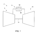
- Turbomachine 2 includes a compressor portion 4 fluidly connected to a combustor assembly 5.
- Turbomachine 2 also includes a turbine portion 10 operatively connected to compressor portion 4 through a common compressor/turbine shaft 12.
- Combustor assembly 5 includes a combustion chamber 38 and is coupled in flow communication with compressor portion 4 and turbine portion 10. With this arrangement, compressed air is passed into combustor assembly 5, mixed with fuel, and combusted to form hot gases. The hot gases are channeled to turbine portion 10 which converts thermal energy from the hot gases into mechanical rotational energy.
- the above described structure has been provided for the sake of completeness, and to enable a better understanding of the exemplary embodiments which are directed to an injection nozzle assembly 60 arranged within combustor assembly 5.
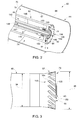
- injection nozzle assembly 60 includes a nozzle body 64 having an outer surface 66 and an inner surface 67 that defines a flow passage 70.
- Injection nozzle assembly 60 is also shown to include a center body 74 that extends within flow passage 70.
- Center body 74 includes a first end 78 that extends to a second end or tip portion 79 through an intermediate portion 80 that defines a fluid passage 82.
- intermediate portion 80 includes a circular cross-section having a first outer dimension 84 and tip portion 79 includes a circular cross-section having a second outer dimension 85.
- First outer dimension 84 defines a first diameter
- second outer dimension 85 defines a second diameter.
- Second outer dimension 85 is greater than first outer dimension 84 so as to define a flared region 87 at tip portion 79.
- tip portion 79 includes an outer face 90 and an inner face 91.
- Outer face 90 includes an outlet 92 which, as will be discussed more fully below, discharges first and second fluids, generally fuel and air, into combustion chamber 38.
- Tip portion 79 also includes a plurality of grooves, one of which is indicated at 100. Grooves 100 extend annularly about tip portion 79 and include a first end portion 104 that extend to a second end portion 105 that is exposed at outer face 90. In the exemplary embodiment shown, second end portion 105 is off-set from first end portion 104. In this manner, a swirl imparted to fluid flow passing through an upstream swozzle (not shown) is channeled through grooves 100 toward combustion chamber 38.
- first end portion 104 may be formed so as to be in-line with second end portion 105.
- Center body 74 is also includes an annular fluid plenum 114 arranged in tip portion 79 between outer face 90 and inner face 91.
- Annular fluid plenum 114 includes a plurality of inlet openings, one of which is indicated at 117, that lead to fluid passage 82 and a plurality of discharge openings 120 that lead to outlet 92.
- fluid such as air
- a first portion of the fluid provides cooling to inner face 91 while a second portion of the fluid passes into annular fluid plenum 114.
- the second portion of fluid flows about annular fluid plenum 114 and passes through discharge openings 120 toward outlet 92.
- the second portion of fluid aids in fuel atomization as will be discussed more fully below.
- Center body 74 is further shown to include a fluid cartridge 140 that passes through fluid passage 82.
- Fluid cartridge 140 includes a first end section 142 that extends to a second end section 143. Second end section 143 is provided with an outlet section 144. First end section 142 is arranged at first end 78 while second end section 143 passes through outlet 92 with outlet section 144 extending proud relative to, or beyond outer face 90.
- Fluid cartridge 140 includes an outer body 146 and an inner body 147 that defines a fluid channel 148.
- Fluid cartridge 140 further includes a shroud 150 positioned at second end section 143.
- Shroud 150 includes a plurality of passages, one of which is indicated at 152, that channel fluid from fluid passage 82 toward outlet section 144. The fluid not only provides cooling to second end section 143 but also contributes to atomization of fluid, such as fuel, passing through fluid cartridge 140 toward combustion chamber 38.
- fluid passing from fluid passage 82 through shroud 150 and annular fluid plenum 114 contributes to atomizing fuel passing from fluid cartridge 140 to enhance combustion.
- fluid, such as air, passing over center body 74 enters into grooves 100 and flows toward combustion chamber 38.
- the fluid passing through grooves 100 reduces combustion dynamics by breaking up large scale vortex rings that may be generated in combustion chamber 38 as well as improves flame stability and enhances turndown by generating longitudinal mixing vortices that increase hot product, and fresh reactant mixing intensity.
- the number and pitch of the grooves can vary depending upon nozzle geometry and nozzle components.
- grooves and annular fluid plenum are shown augmenting a fluid cartridge, other fluid and/or fuel introduction systems could also be employed.
- the particular type of fuel can vary and fuel may include homogeneous fuels, mixtures of fuel, mixtures of fuel and diluents, as well as mixtures of fuel and other constituents.
Landscapes
- Engineering & Computer Science (AREA)
- Chemical & Material Sciences (AREA)
- Combustion & Propulsion (AREA)
- Mechanical Engineering (AREA)
- General Engineering & Computer Science (AREA)
- Nozzles (AREA)
- Turbine Rotor Nozzle Sealing (AREA)
- Nozzles For Spraying Of Liquid Fuel (AREA)
Applications Claiming Priority (1)
| Application Number | Priority Date | Filing Date | Title |
|---|---|---|---|
| US13/221,027 US20130047619A1 (en) | 2011-08-30 | 2011-08-30 | Injection nozzle assembly for a gas turbomachine |
Publications (1)
| Publication Number | Publication Date |
|---|---|
| EP2565541A2 true EP2565541A2 (de) | 2013-03-06 |
Family
ID=46799051
Family Applications (1)
| Application Number | Title | Priority Date | Filing Date |
|---|---|---|---|
| EP12180670A Withdrawn EP2565541A2 (de) | 2011-08-30 | 2012-08-16 | Einspritzdüsenanordnung für eine Gasturbomaschine |
Country Status (3)
| Country | Link |
|---|---|
| US (1) | US20130047619A1 (de) |
| EP (1) | EP2565541A2 (de) |
| CN (1) | CN102966976A (de) |
Families Citing this family (5)
| Publication number | Priority date | Publication date | Assignee | Title |
|---|---|---|---|---|
| US8943832B2 (en) * | 2011-10-26 | 2015-02-03 | General Electric Company | Fuel nozzle assembly for use in turbine engines and methods of assembling same |
| CN104764016A (zh) * | 2015-04-01 | 2015-07-08 | 深圳智慧能源技术有限公司 | 文丘里混合器的喷嘴结构 |
| US10215414B2 (en) | 2015-04-22 | 2019-02-26 | General Electric Company | System and method having fuel nozzle |
| JP6634909B2 (ja) * | 2016-03-18 | 2020-01-22 | 三浦工業株式会社 | ベンチュリノズル及び該ベンチュリノズルを備える燃料供給装置 |
| US11534728B2 (en) * | 2018-11-15 | 2022-12-27 | Caterpillar Inc. | Reductant nozzle with helical channel design |
Family Cites Families (4)
| Publication number | Priority date | Publication date | Assignee | Title |
|---|---|---|---|---|
| US2701164A (en) * | 1951-04-26 | 1955-02-01 | Gen Motors Corp | Duplex fuel nozzle |
| GB1377184A (en) * | 1971-02-02 | 1974-12-11 | Secr Defence | Gas turbine engine combustion apparatus |
| US6968695B2 (en) * | 2002-09-13 | 2005-11-29 | The Boeing Company | Compact lightweight ramjet engines incorporating swirl augmented combustion with improved performance |
| US8661824B2 (en) * | 2009-05-26 | 2014-03-04 | Parker-Hannifin Corporation | Airblast fuel nozzle assembly |
-
2011
- 2011-08-30 US US13/221,027 patent/US20130047619A1/en not_active Abandoned
-
2012
- 2012-08-16 EP EP12180670A patent/EP2565541A2/de not_active Withdrawn
- 2012-08-30 CN CN2012103163567A patent/CN102966976A/zh active Pending
Non-Patent Citations (1)
| Title |
|---|
| 01None |
Also Published As
| Publication number | Publication date |
|---|---|
| US20130047619A1 (en) | 2013-02-28 |
| CN102966976A (zh) | 2013-03-13 |
Similar Documents
| Publication | Publication Date | Title |
|---|---|---|
| US8281596B1 (en) | Combustor assembly for a turbomachine | |
| US8904802B2 (en) | Turbomachine combustor assembly including a vortex modification system | |
| US9714767B2 (en) | Premix fuel nozzle assembly | |
| JP5947515B2 (ja) | 渦発生装置を有する混合管要素を備えたターボ機械 | |
| US7716931B2 (en) | Method and apparatus for assembling gas turbine engine | |
| US9599343B2 (en) | Fuel nozzle for use in a turbine engine and method of assembly | |
| US20150153044A1 (en) | Turbomachine combustor assembly | |
| CN106066049B (zh) | 具有燃料喷嘴的系统和方法 | |
| CN102679399B (zh) | 具有固定火苗用燃料喷嘴的燃气涡轮机燃烧室 | |
| US20100223930A1 (en) | Injection device for a turbomachine | |
| CN103206727A (zh) | 具有可变旋流器的燃气涡轮机燃烧室的空气-燃料预混器 | |
| US20190011130A1 (en) | Systems and methods for a multi-fuel premixing nozzle with integral liquid injectors/evaporators | |
| US10030869B2 (en) | Premix fuel nozzle assembly | |
| EP3376109B1 (de) | Zweistoffbrennstoffdüse mit flüssigbrennstoffspitze | |
| CN116136308B (zh) | 具有压降吹扫通道的旋流器套圈板 | |
| CN103423773A (zh) | 二次燃烧系统 | |
| EP2565541A2 (de) | Einspritzdüsenanordnung für eine Gasturbomaschine | |
| JP2013217635A (ja) | 拡散燃焼器燃料ノズル | |
| US9677766B2 (en) | Fuel nozzle for use in a turbine engine and method of assembly | |
| EP2383517A2 (de) | Gekühlte Einspritzdüsenanordnung für eine Gasturbine | |
| US20150276225A1 (en) | Combustor wth pre-mixing fuel nozzle assembly | |
| US9670846B2 (en) | Enhanced mixing tube elements | |
| EP2385305A2 (de) | Einspritzdüsenanordnung für Turbomaschinen | |
| US10746101B2 (en) | Annular fuel manifold with a deflector |
Legal Events
| Date | Code | Title | Description |
|---|---|---|---|
| PUAI | Public reference made under article 153(3) epc to a published international application that has entered the european phase |
Free format text: ORIGINAL CODE: 0009012 |
|
| AK | Designated contracting states |
Kind code of ref document: A2 Designated state(s): AL AT BE BG CH CY CZ DE DK EE ES FI FR GB GR HR HU IE IS IT LI LT LU LV MC MK MT NL NO PL PT RO RS SE SI SK SM TR |
|
| AX | Request for extension of the european patent |
Extension state: BA ME |
|
| STAA | Information on the status of an ep patent application or granted ep patent |
Free format text: STATUS: THE APPLICATION IS DEEMED TO BE WITHDRAWN |
|
| 18D | Application deemed to be withdrawn |
Effective date: 20150303 |