EP2565552B1 - Wärmetauscher - Google Patents
Wärmetauscher Download PDFInfo
- Publication number
- EP2565552B1 EP2565552B1 EP10850669.2A EP10850669A EP2565552B1 EP 2565552 B1 EP2565552 B1 EP 2565552B1 EP 10850669 A EP10850669 A EP 10850669A EP 2565552 B1 EP2565552 B1 EP 2565552B1
- Authority
- EP
- European Patent Office
- Prior art keywords
- heat absorbing
- pipe
- water
- pipe end
- heat exchanger
- Prior art date
- Legal status (The legal status is an assumption and is not a legal conclusion. Google has not performed a legal analysis and makes no representation as to the accuracy of the status listed.)
- Active
Links
Images


Classifications
-
- F—MECHANICAL ENGINEERING; LIGHTING; HEATING; WEAPONS; BLASTING
- F24—HEATING; RANGES; VENTILATING
- F24H—FLUID HEATERS, e.g. WATER OR AIR HEATERS, HAVING HEAT-GENERATING MEANS, e.g. HEAT PUMPS, IN GENERAL
- F24H8/00—Fluid heaters characterised by means for extracting latent heat from flue gases by means of condensation
-
- F—MECHANICAL ENGINEERING; LIGHTING; HEATING; WEAPONS; BLASTING
- F24—HEATING; RANGES; VENTILATING
- F24H—FLUID HEATERS, e.g. WATER OR AIR HEATERS, HAVING HEAT-GENERATING MEANS, e.g. HEAT PUMPS, IN GENERAL
- F24H9/00—Details
- F24H9/16—Arrangements for water drainage
-
- F—MECHANICAL ENGINEERING; LIGHTING; HEATING; WEAPONS; BLASTING
- F28—HEAT EXCHANGE IN GENERAL
- F28F—DETAILS OF HEAT-EXCHANGE AND HEAT-TRANSFER APPARATUS, OF GENERAL APPLICATION
- F28F9/00—Casings; Header boxes; Auxiliary supports for elements; Auxiliary members within casings
- F28F9/02—Header boxes; End plates
-
- F—MECHANICAL ENGINEERING; LIGHTING; HEATING; WEAPONS; BLASTING
- F24—HEATING; RANGES; VENTILATING
- F24D—DOMESTIC- OR SPACE-HEATING SYSTEMS, e.g. CENTRAL HEATING SYSTEMS; DOMESTIC HOT-WATER SUPPLY SYSTEMS; ELEMENTS OR COMPONENTS THEREFOR
- F24D19/00—Details
- F24D19/0095—Devices for preventing damage by freezing
-
- F—MECHANICAL ENGINEERING; LIGHTING; HEATING; WEAPONS; BLASTING
- F24—HEATING; RANGES; VENTILATING
- F24H—FLUID HEATERS, e.g. WATER OR AIR HEATERS, HAVING HEAT-GENERATING MEANS, e.g. HEAT PUMPS, IN GENERAL
- F24H9/00—Details
- F24H9/14—Arrangements for connecting different sections, e.g. in water heaters
- F24H9/146—Connecting elements of a heat exchanger
-
- F—MECHANICAL ENGINEERING; LIGHTING; HEATING; WEAPONS; BLASTING
- F28—HEAT EXCHANGE IN GENERAL
- F28D—HEAT-EXCHANGE APPARATUS, NOT PROVIDED FOR IN ANOTHER SUBCLASS, IN WHICH THE HEAT-EXCHANGE MEDIA DO NOT COME INTO DIRECT CONTACT
- F28D1/00—Heat-exchange apparatus having stationary conduit assemblies for one heat-exchange medium only, the media being in contact with different sides of the conduit wall, in which the other heat-exchange medium is a large body of fluid, e.g. domestic or motor car radiators
- F28D1/02—Heat-exchange apparatus having stationary conduit assemblies for one heat-exchange medium only, the media being in contact with different sides of the conduit wall, in which the other heat-exchange medium is a large body of fluid, e.g. domestic or motor car radiators with heat-exchange conduits immersed in the body of fluid
- F28D1/04—Heat-exchange apparatus having stationary conduit assemblies for one heat-exchange medium only, the media being in contact with different sides of the conduit wall, in which the other heat-exchange medium is a large body of fluid, e.g. domestic or motor car radiators with heat-exchange conduits immersed in the body of fluid with tubular conduits
- F28D1/047—Heat-exchange apparatus having stationary conduit assemblies for one heat-exchange medium only, the media being in contact with different sides of the conduit wall, in which the other heat-exchange medium is a large body of fluid, e.g. domestic or motor car radiators with heat-exchange conduits immersed in the body of fluid with tubular conduits the conduits being bent, e.g. in a serpentine or zig-zag
- F28D1/0477—Heat-exchange apparatus having stationary conduit assemblies for one heat-exchange medium only, the media being in contact with different sides of the conduit wall, in which the other heat-exchange medium is a large body of fluid, e.g. domestic or motor car radiators with heat-exchange conduits immersed in the body of fluid with tubular conduits the conduits being bent, e.g. in a serpentine or zig-zag the conduits being bent in a serpentine or zig-zag
-
- F—MECHANICAL ENGINEERING; LIGHTING; HEATING; WEAPONS; BLASTING
- F28—HEAT EXCHANGE IN GENERAL
- F28D—HEAT-EXCHANGE APPARATUS, NOT PROVIDED FOR IN ANOTHER SUBCLASS, IN WHICH THE HEAT-EXCHANGE MEDIA DO NOT COME INTO DIRECT CONTACT
- F28D7/00—Heat-exchange apparatus having stationary tubular conduit assemblies for both heat-exchange media, the media being in contact with different sides of a conduit wall
- F28D7/02—Heat-exchange apparatus having stationary tubular conduit assemblies for both heat-exchange media, the media being in contact with different sides of a conduit wall the conduits being helically coiled
- F28D7/024—Heat-exchange apparatus having stationary tubular conduit assemblies for both heat-exchange media, the media being in contact with different sides of a conduit wall the conduits being helically coiled the conduits of only one medium being helically coiled tubes, the coils having a cylindrical configuration
-
- F—MECHANICAL ENGINEERING; LIGHTING; HEATING; WEAPONS; BLASTING
- F28—HEAT EXCHANGE IN GENERAL
- F28F—DETAILS OF HEAT-EXCHANGE AND HEAT-TRANSFER APPARATUS, OF GENERAL APPLICATION
- F28F1/00—Tubular elements; Assemblies of tubular elements
- F28F1/08—Tubular elements crimped or corrugated in longitudinal section
-
- F—MECHANICAL ENGINEERING; LIGHTING; HEATING; WEAPONS; BLASTING
- F28—HEAT EXCHANGE IN GENERAL
- F28F—DETAILS OF HEAT-EXCHANGE AND HEAT-TRANSFER APPARATUS, OF GENERAL APPLICATION
- F28F9/00—Casings; Header boxes; Auxiliary supports for elements; Auxiliary members within casings
- F28F9/02—Header boxes; End plates
- F28F9/026—Header boxes; End plates with static flow control means, e.g. with means for uniformly distributing heat exchange media into conduits
- F28F9/0278—Header boxes; End plates with static flow control means, e.g. with means for uniformly distributing heat exchange media into conduits in the form of stacked distribution plates or perforated plates arranged over end plates
-
- F—MECHANICAL ENGINEERING; LIGHTING; HEATING; WEAPONS; BLASTING
- F24—HEATING; RANGES; VENTILATING
- F24H—FLUID HEATERS, e.g. WATER OR AIR HEATERS, HAVING HEAT-GENERATING MEANS, e.g. HEAT PUMPS, IN GENERAL
- F24H9/00—Details
- F24H9/0005—Details for water heaters
- F24H9/001—Guiding means
- F24H9/0015—Guiding means in water channels
-
- F—MECHANICAL ENGINEERING; LIGHTING; HEATING; WEAPONS; BLASTING
- F28—HEAT EXCHANGE IN GENERAL
- F28D—HEAT-EXCHANGE APPARATUS, NOT PROVIDED FOR IN ANOTHER SUBCLASS, IN WHICH THE HEAT-EXCHANGE MEDIA DO NOT COME INTO DIRECT CONTACT
- F28D21/00—Heat-exchange apparatus not covered by any of the groups F28D1/00 - F28D20/00
- F28D2021/0019—Other heat exchangers for particular applications; Heat exchange systems not otherwise provided for
- F28D2021/0024—Other heat exchangers for particular applications; Heat exchange systems not otherwise provided for for combustion apparatus, e.g. for boilers
-
- F—MECHANICAL ENGINEERING; LIGHTING; HEATING; WEAPONS; BLASTING
- F28—HEAT EXCHANGE IN GENERAL
- F28F—DETAILS OF HEAT-EXCHANGE AND HEAT-TRANSFER APPARATUS, OF GENERAL APPLICATION
- F28F2265/00—Safety or protection arrangements; Arrangements for preventing malfunction
- F28F2265/06—Safety or protection arrangements; Arrangements for preventing malfunction by using means for draining heat exchange media from heat exchangers
-
- Y—GENERAL TAGGING OF NEW TECHNOLOGICAL DEVELOPMENTS; GENERAL TAGGING OF CROSS-SECTIONAL TECHNOLOGIES SPANNING OVER SEVERAL SECTIONS OF THE IPC; TECHNICAL SUBJECTS COVERED BY FORMER USPC CROSS-REFERENCE ART COLLECTIONS [XRACs] AND DIGESTS
- Y02—TECHNOLOGIES OR APPLICATIONS FOR MITIGATION OR ADAPTATION AGAINST CLIMATE CHANGE
- Y02B—CLIMATE CHANGE MITIGATION TECHNOLOGIES RELATED TO BUILDINGS, e.g. HOUSING, HOUSE APPLIANCES OR RELATED END-USER APPLICATIONS
- Y02B30/00—Energy efficient heating, ventilation or air conditioning [HVAC]
Definitions
- the present invention relates to a heat exchanger which carries out heat-exchange heating of the water flowing through heat absorbing pipes through two headers by combustion exhaust gas.
- a latent heat recovery type heat exchanger mounted in a high thermal efficiency water heater is adapted to recover latent heat by providing a plurality of heat absorbing pipes within a casing which is the passage of combustion exhaust gas, arranging both pipe ends of each of the heat absorbing pipes at a predetermined vertical interval, connecting the both ends of each of the heat absorbing pipes to two headers provided on a side plate of the casing, respectively, and introducing water from external pipe to the heat absorbing pipes through the inflow header to condense moisture in the combustion exhaust gas (see, for example, PTL 1).
- a reduction in diameter of the heat absorbing pipe is promoted in order to realize further downsizing and further improvement in thermal efficiency. That is, the reduction in diameter of the heat absorbing pipe allows more pipes to be provided in a limited space within the casing and increases a heat transfer area of the entire heat absorbing pipe.
- the reduction in diameter of the heat absorbing pipe poses a problem in that when water is removed from the heat absorbing pipe in order to prevent water inside the heat absorbing pipe from freezing during wintertime, a water film is formed at a pipe end opening of the heat absorbing pipe due to water surface tension, causing the water to remain at a downstream portion of the heat absorbing pipe in a water flow direction.
- some measures need to be taken for smoothly removing water in the heat absorbing pipe.
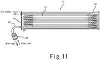
- Fig. 11 illustrates a conventional heat exchanger 9.
- the heat exchanger 9 includes a plurality of heat absorbing pipes 91 in a casing 90, each having both ends penetrating a side plate 92 of the casing 90, a downward-bending extended tubular body 93 connected to one of the pipe ends of each of the heat absorbing pipes 91 appeared from the side plate 92, and a header 94 mounted to a lower end of the extended tubular body 93 and is configured to drain water in the heat absorbing pipes 91 through the header 94 (see, for example, PTL 2).
- the extended tubular body 93 or the header 94 is provided extending outside of the casing 90, impeding downsizing of the heat exchanger 9. Further, the extended tubular body 93 needs to be provided for each of the plurality of heat absorbing pipes 91, resulting in an increase in the number of components or brazing portions, which in turn increases the number of assembling processes.
- the present invention has been made in view of the above situation, and an object thereof is to provide a heat exchanger that does not impede downsizing and removes water in the heat absorbing pipe adequately with a simple configuration even when the reduction in diameter of the heat absorbing pipe is made.
- a heat exchanger is a heat exchanger in which heat absorbing pipes are disposed in a multi-tier arrangement within a casing which is the passage of combustion exhaust gas, both pipe ends of each of the heat absorbing pipes are connected respectively to two headers provided on a side plate of the casing, and water introduced from an external pipe to each of the heat absorbing pipes through the header is heat-exchanged and heated by combustion exhaust gas.
- the pipe ends of the heat absorbing pipes are arranged at a predetermined vertical interval.
- a drainage plate for forming a drainage passage through which the water that has reached the pipe end openings of respective heat absorbing pipes is removed during drainage operation for the heat absorbing pipes is disposed in the header disposed on a lower side of the heat absorbing pipes so as to face a number of the pipe end openings vertically arranged in a state of continuous.
- the water that has reached the lower side pipe end opening is smoothly discharged from the pipe end opening to a connecting port of the header for connecting the external pipe through the drainage passage formed by the drainage plate.
- the water does not remain at a downstream portion of the heat absorbing pipe in a water flow direction, and the water can reliably be removed from the heat absorbing pipe.
- This effect can be achieved by a simple configuration in which the drainage plate is provided in the header, thus not impeding downsizing of the heat exchanger.
- the drainage passage is preferably composed of a vertically extending concave groove formed in the drainage plate, and the concave groove preferably has a groove width smaller than a diameter of each of the pipe end openings and communicates with the pipe end openings.
- the drainage passage may be composed of a gap between the pipe end openings and the drainage plate, and a width of the gap may be set equal to or less than a swelling amount of a water film to be formed at the pipe end opening due to the water surface tension.
- the drainage plate is formed of a water permeable member.
- the water can pass smoothly through the drainage plate, so that flow of water to the heat absorbing pipes through the header is not impeded in normal hot water feeding operation.
- Lower ends of the lower side pipe end openings of the heat absorbing pipes are preferably positioned above a lower end of a connecting port of the header for connecting the external pipe.
- the heat absorbing pipes are preferably disposed tilted downward to the front and vertically such that pipe cross sections are staggered in a zig-zag alignment as viewed in a vertical cross section, and in lower side heat absorbing pipes, the pipe end opening of the lowermost heat absorbing pipe is preferably positioned rearward of the pipe end opening of the second lowest heat absorbing pipe.
- the water can reliably be removed from the heat absorbing pipes with a simple configuration in which the drainage plate is provided so as to face the pipe end openings of the lower side heat absorbing pipes. This prevents the water from remaining in the heat absorbing pipes after the drainage operation, which in turn prevents the water remaining in the heat absorbing pipes from freezing during wintertime to destroy the heat absorbing pipes.
- a heat exchanger capable of achieving downsizing and high thermal efficiency, as well as, capable of reliably removing the water from the heat absorbing pipes can be provided.
- a latent heat recovery type water heater 1 includes, in an outer casing 10, a combustion casing 30 incorporating a gas burner 3, a main heat exchanger 4 disposed above the combustion casing 30 and configured to mainly recover sensible heat in combustion exhaust gas, and a sub heat exchanger 5 disposed above the main heat exchanger 4 and configured to mainly recover latent heat in the combustion exhaust gas.
- An air supply fan 2 that supplies combustion air into the combustion casing 30 is installed at a bottom portion of the combustion casing 30.
- the main heat exchanger 4 includes, in a rectangular-cylindrical body portion 40 with opened top and bottom thereof, a plurality of heat absorbing fins 40a arranged side by side at intervals and a heat absorbing pipe 41 that penetrates the heat absorbing fins 40a in a meandering state.
- a lower end of the body portion 40 is connected with an upper end of the combustion casing 30, and an upper end of the body portion 40 is connected with a lower end of a casing 50 of the sub heat exchanger 5.
- a downstream end of the heat absorbing pipe 41 of the main heat exchanger 4 is connected with a hot water pipe 61 leading to a hot water supply destination P such as a faucet or a shower, and an upstream end of the heat absorbing pipe 41 is connected with a connecting pipe 62 leading to the sub heat exchanger 5.
- the sub heat exchanger 5 is a latent-heat heat exchanger and includes, in the rectangular box-shaped casing 50, a plurality of (in this case, eight) heat absorbing pipes 51.
- a lateral passage 500 extending in a front-rear direction is formed in the casing 50, and the heat absorbing pipes 51 are mounted in the lateral passage 500.
- An inflow header 54 and an outflow header 55 are provided on a side plate 52 on one side of the casing 50 in the lateral direction.
- One end portions of the plurality of the heat absorbing pipes 51 are connected to the inflow header 54, and the other end portions thereof are connected to the outflow header 55.
- An exhaust inlet port 501 allowing the lateral passage 500 and an inner space of the body portion 40 to communicate with each other is formed at a bottom rear portion of the casing 50, and an exhaust port 502 allowing the lateral passage 500 and a space outside the outer casing 10 to communicate with each other is formed at an upper portion of the casing 50.
- combustion exhaust gas of the gas burner 3 passes through the body portion 40 of the main heat exchanger 4, guided from the exhaust inlet port 501 to the lateral passage 500, and passes through gaps between the heat absorbing pipes 51, to be finally discharged outside the outer casing 10 through the exhaust port 502.
- water supplied from waterworks to the inflow header 54 of the sub heat exchanger 5 through a water supply pipe 63 is heat-exchanged and heated by the latent heat in the combustion exhaust gas when passing through the heat absorbing pipes 51 and, thereafter, guided to the main heat exchanger 4 through the outflow header 55 and connecting pipe 62 sequentially.
- the water guided to the main heat exchanger 4 is heat-exchanged and heated by the sensible heat in the combustion exhaust gas when passing through the heat absorbing pipe 41 of the main heat exchanger 4 and then supplied to the hot water supply destination P through the hot water pipe 61.
- the heat absorbing pipes 51 of the sub heat exchanger 5 are each obtained by bending, in a meandering state, a corrugated pipe formed of highly corrosion-resistant metal, such as stainless or titanium.
- Inlet side pipe ends 511 of the respective heat absorbing pipes 51 and outlet side pipe ends 512 thereof are connected, in a penetrating manner, to two concave portions 520 formed in the side plate 52 on one side of the casing 50, respectively.
- the inflow header 54 that collectively connects the inlet side pipe ends 511 to the water supply pipe 63 is provided in the concave portion 520 on the side of the inlet side pipe ends 511
- the outflow header 55 that collectively connects the outlet side pipe ends 512 to the connecting pipe 62 is provided in the concave portion 520 on the side of the outlet side pipe ends 512.
- the inflow header 54 is disposed lower than the outflow header 55 and, in conformity with the positional relationship between the inflow header 54 and outflow header 55, the heat absorbing pipes 51 are disposed tilted downward to the front at a predetermined angle (e.g., 5°) such that the inlet side pipe ends 511 thereof are positioned lower than the outlet side pipe ends 512.
- the heat absorbing pipes 51 are disposed vertically such that cross sections thereof are staggered in a zig-zag alignment as viewed in a vertical cross section and that the lowermost heat absorbing pipe 51 is positioned rearward of the second lowest heat absorbing pipe 51.
- the concave portion 520 is formed into a vertically long rectangular shape and tilted toward the front side of the casing 50 at a predetermined angle (e.g., 5°).
- the inlet side pipe ends 511 of the heat absorbing pipes 51 are arranged in two rows along a longitudinal direction of the concave portion 520 and staggered in a zig-zag alignment.
- the inlet side pipe end 511 of the lowermost heat absorbing pipe 51 is positioned rearward of the inlet side pipe end 511 of the second lowest heat absorbing pipe 51.
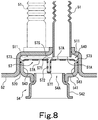
- Pipe end opening portions 51A opened at the respective inlet side pipe ends 511 are covered by a header body 541 of the inflow header 54 from outside the casing 50.
- a tubular joint portion 542 to be connected to the water supply pipe 63 is provided at a lower portion of an outer surface of the header body 541, and the pipe end opening portions 51A communicate with a connecting port 54A opened at the joint portion 542 through a closed space within the inflow header 54.
- a joint portion 552 of the outflow header 55 to be connected to the connecting pipe 62 is provided at an upper portion of an outer surface of a header body 551 of the outflow header 55 and positioned higher than the joint portion 542 of the inflow header 54.
- a reduction in diameter of the heat absorbing pipe 51 has been made so as to achieve further downsizing and high thermal efficiency.
- eight heat absorbing pipes 51 each having the pipe end opening portion 51A with a diameter of 10 mm are arranged in a zig-zag alignment and accommodated within the lateral space 500 of the casing 50. Disposing a number of the heat absorbing pipes 51 within the limited space in this manner leads to downsizing, as well as, increases a heat transfer area of the entire heat absorbing pipe 51 to result in high thermal efficiency.
- a water film may be formed at the pipe end opening portion 51A due to water surface tension when drainage from the heat absorbing pipe 51 is conducted, which may cause the water to remain at a downstream portion of the heat absorbing pipe 51.
- the following configuration is employed in order to allow the water in the heat absorbing pipe 51 to be smoothly removed even when the reduction in diameter of the heat absorbing pipe 51 is made.
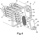
- the lower side inflow header 54 covers, from outside the casing 50, the entire concave portion 520 by the header body 541 formed into a shallow container shape having a peripheral wall 543 over the entire periphery thereof.
- the peripheral wall 543 is fixed in a closely contacting manner to the entire inner periphery of the concave portion 520, and the closed space 540 is formed between the header body 541 and concave portion 520.
- a drainage plate 56 illustrated in Fig. 7 which is formed of a punching metal is accommodated in the closed space 540.
- This drainage plate 56 forms a drainage passage for removing water that has reached the pipe end opening portions 51A of the heat absorbing pipes 51 when the water is removed from the heat absorbing pipe 51. More specifically, the drainage plate 56 faces the pipe end opening portions 51A of the heat absorbing pipes 51.
- Two rows of vertically extending concave grooves 561 are formed on one surface of the drainage plate 56 that faces the pipe end opening portions 51A.
- the concave grooves 561 are disposed so as to face continuous with respect to the pipe end opening portions 51A of each of the columns arranged in two rows to the left and right one column is made up of four pipe end opening portions 51A.
- Each of the concave grooves 561 each serve as the drainage passage for removing water that has reached the pipe end opening portions 51A when the water is removed from the heat absorbing pipe 51.
- Each of the concave grooves 561 has a width smaller (for example, diameter of each pipe end opening portion 51A is set to 10 mm, and width of the each concave groove 561 is set to approximately 1 mm) than the diameter of each of the pipe end opening portions 51A, and a large number of punched holes 56A formed in the drainage plate 56 each have a diameter smaller than the diameter of each of the pipe end opening portions 51A.
- Projecting ribs 562 constituting each of the concave grooves 561 are formed in the drainage plate 56 so as to ensure strength of the drainage plate 56. Further, bent portions 563 each bent obtusely toward the projecting rib 562 side are formed on both ends of the drainage plate 56. Furthermore, the drainage plate 56 has an outer shape substantially corresponding to the inner periphery of the concave portion 520.
- the projecting ribs 562 are formed so as to have a height such that top portions 56T thereof make contact with an inside of the header body 541.
- the bent portions 563 are formed such that leading ends thereof make contact with an upper end of the peripheral wall 543 of the header body 541. A surface of the drainage plate 56 on a side on which the concave grooves 561 are opened contacts a periphery of the pipe end openings 51A.
- drain plugs provided respectively in the water supply pipe 63 and hot water pipe 61 are opened to start the operation of removing water from the heat absorbing pipes 51 of the sub heat exchanger 5
- the water in the heat absorbing pipes 51 is first guided to the pipe end openings 51A side of a water inlet side by a difference in height between the inlet side and an outlet side of the heat absorbing pipes 51, and passes through the plurality of pinched holes 56A formed in the drainage plate 56 to be smoothly discharged to the connecting port 54A side.
- the water that has reached the pipe end opening portion 51A permeates the concave groove 561 by capillary action in the concave groove 561, and that the water that has permeated the concave groove 561 flows down along the concave groove 561 as a joint result of its own weight and capillary action.
- the water that has reached the pipe end opening portions 51A is thus made to flow sequentially through the concave grooves 561, and it follows that even when the hydraulic head pressure resulting from the height difference becomes small, the water in the water heat absorbing pipes 51 does not form the water films at the pipe end opening portions 51A but is discharged to the connecting port 54A side reliably.
- the diameter of the heat absorbing pipe 51 is reduced, the water does not remain at the downstream portion of the heat absorbing pipes 51 in the water flow direction, and the water can reliably be removed from the heat absorbing pipes 51.
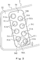
- the following configuration is adopted. That is, in the inflow header 54 arranged on the lower position side, the lower ends of the pipe end openings 51A of all the heat absorbing pipes 51 are positioned above a lower end of the connecting port 54A of the inflow header 54, as illustrated in Figs. 1 and 3 .
- the water that has reached the lower side pipe end opening portions 51A is smoothly discharged from the pipe end opening portions 51A to the connection port 54A of the inflow header 54 by the height difference between the lower end of the pipe end opening portion 51A and lower end of the connection port 54A of the inflow header 54.
- the inlet side pipe end 511 of the lowermost heat absorbing pipe 51 is positioned rearward of the inlet side pipe end 511 of the second lowest heat absorbing pipe 51.
- the sub heat exchanger 5 of the present embodiment water can reliably be removed from the heat absorbing pipe 51 even when the reduction in diameter of the heat absorbing pipe 51 is made. This prevents a problem that the heat absorbing pipes 51 are destroyed by freezing due to the water remaining in the heat absorbing pipes 51, in spite of having done drainage operation.
- the sub heat exchanger 5 capable of achieving further downsizing and high terminal efficiency, as well as, capable of adequately removing water from the heat absorbing pipes 51 with comparatively simple configurations in which the lower ends of the pipe end opening portions 51A are positioned above the lower end of the connecting port 54A and in which the drainage plate 56 is provided so as to face the pipe end opening portions 51A in the inflow header 54.
- the drainage plate 56 formed of the punching metal allows water that has been guided to the inlet side pipe end 511 of the heat absorbing pipe 51 to smoothly pass through the drainage plate 56, so that passage of water to the sub heat exchanger 5 is not impeded in normal hot water feeding operation.
Landscapes
- Engineering & Computer Science (AREA)
- Physics & Mathematics (AREA)
- Thermal Sciences (AREA)
- Mechanical Engineering (AREA)
- General Engineering & Computer Science (AREA)
- Chemical & Material Sciences (AREA)
- Combustion & Propulsion (AREA)
- Geometry (AREA)
- Details Of Fluid Heaters (AREA)
- Instantaneous Water Boilers, Portable Hot-Water Supply Apparatuses, And Control Of Portable Hot-Water Supply Apparatuses (AREA)
- Heat-Exchange Devices With Radiators And Conduit Assemblies (AREA)
Claims (6)
- Wärmetauscher (5), in dem Wärme aufnehmende Rohre (51) in einer Anordnung mit mehreren Ebenen innerhalb eines Gehäuses (50) angeordnet sind, das den Durchgang von Verbrennungsabgas bildet, wobei beide Rohrenden (511, 512) von jedem der Wärme aufnehmenden Rohre (51) jeweils an zwei auf einer Seitenplatte (52) des Gehäuses (50) vorgesehenen Köpfe (54, 55) angeschlossen sind und von einem externen Rohr (63) zu jedem der Wärme aufnehmenden Rohre (51) durch den Kopf (54) eingeführtes Wasser einem Wärmeaustausch unterzogen und durch Verbrennungsabgas erwärmt wird,
wobei die Rohrenden (511, 512) der Wärme aufnehmenden Rohre (51) in einem vorbestimmten senkrechten Abstand angeordnet sind, dadurch gekennzeichnet, dass
eine Drainageplatte (56) zur Bildung eines Drainagedurchgangs, durch welchen Wasser, das die Rohrendeöffnungen (51A) von jeweiligen Wärme aufnehmenden Rohren (51) erreicht hat, während des Drainagevorgangs für die Wärme aufnehmenden Rohre (51) entfernt wird, im an einer unteren Seite der Wärme aufnehmenden Rohre (51) angeordneten Kopf (54) angeordnet ist, um einer Anzahl senkrecht in einem ununterbrochenem Zustand angeordneten Rohrendeöffnungen (51A) gegenüberzuliegen. - Wärmetauscher (5) nach Anspruch 1, wobei der Drainagedurchgang aus einer konkaven, sich senkrecht erstreckenden Nut (561) besteht, die in der Drainageplatte (56) ausgebildet ist, und
die konkave Nut (561) eine Nutbreite hat, die kleiner als ein Durchmesser von jeder der Rohrendeöffnungen (51A) ist, und mit den Rohrendeöffnungen (51A) verbindet. - Wärmetauscher (5) nach Anspruch 1, wobei der Drainagedurchgang aus einem Spalt (57S) zwischen den Rohrendeöffnungen (51A) und der Drainageplatte (56) besteht und
eine Breite des Spalts (57S) gleich oder geringer als ein Quellungsmaß eines an der Rohrendeöffnung (51A) aufgrund der Wasseroberflächenspannung zu bildenden Wasserfilms eingestellt ist. - Wärmetauscher (5) nach einem der Ansprüche 1 bis 3, wobei
die Drainageplatte (56) aus einem wasserdurchlässigen Element gebildet ist. - Wärmetauscher (5) nach einem der Ansprüche 1 bis 4, wobei
untere Enden der zur unteren Seite gehörenden Rohrendeöffnungen (51A) der Wärme aufnehmenden Rohre (51) oberhalb eines unteren Endes einer Anschlussöffnung (54A) des Kopfes (54) zum Anschluss des externen Rohres (63) positioniert sind. - Wärmetauscher (5) nach einem der Ansprüche 1 bis 5, wobei
die Wärme aufnehmenden Rohre (51) derart nach unten zur Frontseite geneigt und senkrecht angeordnet sind, dass, in einem senkrechten Querschnitt gesehen, Rohrquerschnitte in einer Zig-Zag-Ausrichtung versetzt sind, und
in unterer Seite der Wärme aufnehmenden Rohre (51), die Rohrendeöffnung (51A) des untersten Wärme aufnehmenden Rohrs (51) rückwärtig von der Rohrendeöffnung (51A) des zweituntersten Wärme aufnehmenden Rohres (51) positioniert ist.
Applications Claiming Priority (1)
| Application Number | Priority Date | Filing Date | Title |
|---|---|---|---|
| PCT/JP2010/057375 WO2011135650A1 (ja) | 2010-04-26 | 2010-04-26 | 熱交換器 |
Publications (3)
| Publication Number | Publication Date |
|---|---|
| EP2565552A1 EP2565552A1 (de) | 2013-03-06 |
| EP2565552A4 EP2565552A4 (de) | 2014-08-27 |
| EP2565552B1 true EP2565552B1 (de) | 2017-01-25 |
Family
ID=44860997
Family Applications (1)
| Application Number | Title | Priority Date | Filing Date |
|---|---|---|---|
| EP10850669.2A Active EP2565552B1 (de) | 2010-04-26 | 2010-04-26 | Wärmetauscher |
Country Status (6)
| Country | Link |
|---|---|
| US (1) | US9709341B2 (de) |
| EP (1) | EP2565552B1 (de) |
| KR (1) | KR101666253B1 (de) |
| CN (1) | CN102906510B (de) |
| CA (1) | CA2797413C (de) |
| WO (1) | WO2011135650A1 (de) |
Families Citing this family (24)
| Publication number | Priority date | Publication date | Assignee | Title |
|---|---|---|---|---|
| DE102012023125B3 (de) * | 2012-11-27 | 2013-11-28 | Modine Manufacturing Co. | Herstellungsverfahren gelöteter Plattenwärmetauscher, sowie danach hergestellte Plattenwärmetauscher |
| JP5951467B2 (ja) * | 2012-12-20 | 2016-07-13 | 株式会社コロナ | 潜熱回収型給湯機の二次熱交換装置 |
| US9964333B2 (en) * | 2013-05-28 | 2018-05-08 | Trane International Inc. | System and method for furnace fluid flow management |
| JP6173820B2 (ja) * | 2013-08-01 | 2017-08-02 | 株式会社神戸製鋼所 | ガス圧縮機用の熱交換器 |
| DE102013014987B4 (de) * | 2013-09-07 | 2015-05-07 | Martin Kronstedt | Wärmetauscher-Bauteil aus Wellrohr, Spiralrohr oder Wellschlauch |
| US20160215735A1 (en) * | 2013-09-11 | 2016-07-28 | International Engine Intellectual Property Company, Llc | Thermal screen for an egr cooler |
| JP6153458B2 (ja) * | 2013-12-09 | 2017-06-28 | リンナイ株式会社 | 熱交換器 |
| CN105466019B (zh) * | 2014-09-10 | 2018-08-24 | 关隆股份有限公司 | 热水器及其二次热交换器 |
| WO2016055392A1 (en) * | 2014-10-08 | 2016-04-14 | Bekaert Combustion Technology B.V. | Heat exchanger |
| JP6293685B2 (ja) * | 2015-02-04 | 2018-03-14 | リンナイ株式会社 | 強制給排気式暖房装置 |
| PL3411635T3 (pl) * | 2016-02-01 | 2020-06-29 | Intergas Heating Assets B.V. | Kocioł z gorącą wodą, system odprowadzania gazów spalinowych dla kotła i sposób podgrzewania płynu |
| US20180023895A1 (en) * | 2016-07-22 | 2018-01-25 | Trane International Inc. | Enhanced Tubular Heat Exchanger |
| JP6905806B2 (ja) * | 2016-08-25 | 2021-07-21 | リンナイ株式会社 | 熱交換器及びそれを用いた給湯装置 |
| US20180106500A1 (en) * | 2016-10-18 | 2018-04-19 | Trane International Inc. | Enhanced Tubular Heat Exchanger |
| JP2018132256A (ja) * | 2017-02-16 | 2018-08-23 | リンナイ株式会社 | 熱交換器及びそれを用いた給湯装置 |
| US10401055B2 (en) * | 2017-03-03 | 2019-09-03 | Trane International Inc. | Reduced drag combustion pass in a tubular heat exchanger |
| JP7052341B2 (ja) * | 2017-12-26 | 2022-04-12 | 株式会社ノーリツ | 熱交換装置および熱源機 |
| CN108419412B (zh) * | 2018-02-08 | 2020-01-14 | 惠州汉旭五金塑胶科技有限公司 | 一种具有杂质过滤功能的水冷排 |
| JP2019207068A (ja) * | 2018-05-29 | 2019-12-05 | 株式会社ノーリツ | 熱交換器およびこれを備えた温水装置 |
| JP7241595B2 (ja) * | 2019-04-23 | 2023-03-17 | リンナイ株式会社 | 熱交換器、及び、それを備えた燃焼装置、並びに、水抜き補助具 |
| US11480392B2 (en) * | 2019-07-19 | 2022-10-25 | Rheem Manufacturing Company | Heat exchanger transfer tubes |
| CN111947297B (zh) * | 2020-08-17 | 2021-11-16 | 珠海格力电器股份有限公司 | 燃气热水器、燃气热水器的控制方法、装置及存储介质 |
| JP7653145B2 (ja) * | 2021-10-21 | 2025-03-28 | 株式会社パロマ | 給湯器 |
| US12405030B2 (en) * | 2021-11-23 | 2025-09-02 | Tyco Fire & Security Gmbh | Top fired outdoor gas heat exchanger |
Family Cites Families (17)
| Publication number | Priority date | Publication date | Assignee | Title |
|---|---|---|---|---|
| US406512A (en) * | 1889-07-09 | Feed-water heater | ||
| US2488623A (en) * | 1944-07-31 | 1949-11-22 | Modine Mfg Co | Heat exchanger |
| US2915294A (en) * | 1958-03-19 | 1959-12-01 | Young Radiator Co | Heat exchanger and turbulator retainer therefor |
| US3191672A (en) * | 1962-03-26 | 1965-06-29 | Walking Stick Radiators Inc | Insertable slag trap adapter for automobile radiators |
| US3706534A (en) * | 1970-11-03 | 1972-12-19 | Shell Oil Co | Mixing nozzle for gases |
| US5465783A (en) * | 1994-03-04 | 1995-11-14 | Fedco Automotive Components Company, Inc. | Sacrificial erosion bridge for a heat exchanger |
| CN1526063A (zh) * | 2001-03-14 | 2004-09-01 | 昭和电工株式会社 | 分层型热交换器、汽车空调用的分层型蒸发器和致冷系统 |
| JP4180935B2 (ja) * | 2003-02-04 | 2008-11-12 | リンナイ株式会社 | 熱交換器及び温水加熱器 |
| DE112005000642T5 (de) * | 2004-03-25 | 2007-02-22 | Noritz Corporation, Kobe | Heizeinrichtung |
| JP4655621B2 (ja) * | 2004-12-22 | 2011-03-23 | 株式会社ノーリツ | 給湯装置 |
| JP2007093197A (ja) * | 2005-09-01 | 2007-04-12 | Showa Denko Kk | 熱交換器およびその製造方法 |
| JP4574535B2 (ja) * | 2005-12-16 | 2010-11-04 | リンナイ株式会社 | 潜熱回収型熱交換器の製造方法。 |
| JP2007170733A (ja) * | 2005-12-21 | 2007-07-05 | Rinnai Corp | 潜熱回収型熱交換器 |
| CN101395433B (zh) * | 2006-04-24 | 2010-05-19 | 林内株式会社 | 单罐式组合热源机 |
| JP4929866B2 (ja) * | 2006-06-16 | 2012-05-09 | 株式会社ノーリツ | 熱交換器およびこれを備えた温水装置 |
| US20100089559A1 (en) * | 2006-10-13 | 2010-04-15 | Carrier Corporation | Method and apparatus for improving distribution of fluid in a heat exchanger |
| JP2010048424A (ja) * | 2008-08-19 | 2010-03-04 | Noritz Corp | 熱交換器およびこれを備えた温水装置 |
-
2010
- 2010-04-26 EP EP10850669.2A patent/EP2565552B1/de active Active
- 2010-04-26 US US13/643,160 patent/US9709341B2/en active Active
- 2010-04-26 CA CA2797413A patent/CA2797413C/en active Active
- 2010-04-26 WO PCT/JP2010/057375 patent/WO2011135650A1/ja not_active Ceased
- 2010-04-26 KR KR1020127030960A patent/KR101666253B1/ko active Active
- 2010-04-26 CN CN201080066441.1A patent/CN102906510B/zh active Active
Non-Patent Citations (1)
| Title |
|---|
| None * |
Also Published As
| Publication number | Publication date |
|---|---|
| US20130112384A1 (en) | 2013-05-09 |
| CA2797413C (en) | 2017-02-28 |
| EP2565552A4 (de) | 2014-08-27 |
| WO2011135650A1 (ja) | 2011-11-03 |
| CN102906510B (zh) | 2015-05-20 |
| KR101666253B1 (ko) | 2016-10-13 |
| CN102906510A (zh) | 2013-01-30 |
| US9709341B2 (en) | 2017-07-18 |
| KR20130058010A (ko) | 2013-06-03 |
| CA2797413A1 (en) | 2011-11-03 |
| EP2565552A1 (de) | 2013-03-06 |
Similar Documents
| Publication | Publication Date | Title |
|---|---|---|
| EP2565552B1 (de) | Wärmetauscher | |
| WO2016013369A1 (ja) | フィンアンドチューブ式の熱交換器およびこれを備えた給湯装置 | |
| CN110542211B (zh) | 换热器及具备该换热器的热水装置 | |
| JP5818071B2 (ja) | 給湯装置 | |
| KR100529788B1 (ko) | 열교환기 | |
| JP5158404B2 (ja) | 熱交換器および温水装置 | |
| CN102822617A (zh) | 换热器 | |
| CN107782171B (zh) | 热交换器以及热水器 | |
| US20150241130A1 (en) | Condensation heat exchanger having dummy pipe | |
| JP5207053B2 (ja) | 熱交換器および温水装置 | |
| JP5030981B2 (ja) | 熱交換器 | |
| JP5405395B2 (ja) | 熱交換器 | |
| KR101031101B1 (ko) | 분할형 열교환기 | |
| JP2010139110A (ja) | 潜熱回収型熱交換器 | |
| JP6153458B2 (ja) | 熱交換器 | |
| JP5212703B2 (ja) | 給湯装置 | |
| JP5234349B2 (ja) | 熱交換器および温水装置 | |
| JP5234350B2 (ja) | 熱交換器および温水装置 | |
| JP6124060B2 (ja) | 熱交換器及び燃焼装置 | |
| JP4636325B2 (ja) | 加熱装置 | |
| KR100656517B1 (ko) | 폐열 회수기 | |
| CN110220407B (zh) | 具有自净水功能的冷凝换热器 | |
| US20180231333A1 (en) | Heat exchanger and water heater | |
| JP5234509B2 (ja) | 熱交換器および温水装置 | |
| KR20100094744A (ko) | 수관 연관 복합 보일러 |
Legal Events
| Date | Code | Title | Description |
|---|---|---|---|
| PUAI | Public reference made under article 153(3) epc to a published international application that has entered the european phase |
Free format text: ORIGINAL CODE: 0009012 |
|
| 17P | Request for examination filed |
Effective date: 20121023 |
|
| AK | Designated contracting states |
Kind code of ref document: A1 Designated state(s): AT BE BG CH CY CZ DE DK EE ES FI FR GB GR HR HU IE IS IT LI LT LU LV MC MK MT NL NO PL PT RO SE SI SK SM TR |
|
| DAX | Request for extension of the european patent (deleted) | ||
| A4 | Supplementary search report drawn up and despatched |
Effective date: 20140730 |
|
| RIC1 | Information provided on ipc code assigned before grant |
Ipc: F24H 9/16 20060101ALI20140724BHEP Ipc: F24H 9/00 20060101AFI20140724BHEP |
|
| GRAP | Despatch of communication of intention to grant a patent |
Free format text: ORIGINAL CODE: EPIDOSNIGR1 |
|
| INTG | Intention to grant announced |
Effective date: 20160811 |
|
| STAA | Information on the status of an ep patent application or granted ep patent |
Free format text: STATUS: GRANT OF PATENT IS INTENDED |
|
| GRAS | Grant fee paid |
Free format text: ORIGINAL CODE: EPIDOSNIGR3 |
|
| GRAA | (expected) grant |
Free format text: ORIGINAL CODE: 0009210 |
|
| STAA | Information on the status of an ep patent application or granted ep patent |
Free format text: STATUS: THE PATENT HAS BEEN GRANTED |
|
| AK | Designated contracting states |
Kind code of ref document: B1 Designated state(s): AT BE BG CH CY CZ DE DK EE ES FI FR GB GR HR HU IE IS IT LI LT LU LV MC MK MT NL NO PL PT RO SE SI SK SM TR |
|
| REG | Reference to a national code |
Ref country code: GB Ref legal event code: FG4D |
|
| REG | Reference to a national code |
Ref country code: CH Ref legal event code: EP |
|
| REG | Reference to a national code |
Ref country code: AT Ref legal event code: REF Ref document number: 864381 Country of ref document: AT Kind code of ref document: T Effective date: 20170215 |
|
| REG | Reference to a national code |
Ref country code: IE Ref legal event code: FG4D |
|
| REG | Reference to a national code |
Ref country code: DE Ref legal event code: R096 Ref document number: 602010039889 Country of ref document: DE |
|
| REG | Reference to a national code |
Ref country code: LT Ref legal event code: MG4D |
|
| REG | Reference to a national code |
Ref country code: NL Ref legal event code: MP Effective date: 20170125 |
|
| REG | Reference to a national code |
Ref country code: AT Ref legal event code: MK05 Ref document number: 864381 Country of ref document: AT Kind code of ref document: T Effective date: 20170125 |
|
| PG25 | Lapsed in a contracting state [announced via postgrant information from national office to epo] |
Ref country code: NL Free format text: LAPSE BECAUSE OF FAILURE TO SUBMIT A TRANSLATION OF THE DESCRIPTION OR TO PAY THE FEE WITHIN THE PRESCRIBED TIME-LIMIT Effective date: 20170125 |
|
| PG25 | Lapsed in a contracting state [announced via postgrant information from national office to epo] |
Ref country code: IS Free format text: LAPSE BECAUSE OF FAILURE TO SUBMIT A TRANSLATION OF THE DESCRIPTION OR TO PAY THE FEE WITHIN THE PRESCRIBED TIME-LIMIT Effective date: 20170525 Ref country code: LT Free format text: LAPSE BECAUSE OF FAILURE TO SUBMIT A TRANSLATION OF THE DESCRIPTION OR TO PAY THE FEE WITHIN THE PRESCRIBED TIME-LIMIT Effective date: 20170125 Ref country code: NO Free format text: LAPSE BECAUSE OF FAILURE TO SUBMIT A TRANSLATION OF THE DESCRIPTION OR TO PAY THE FEE WITHIN THE PRESCRIBED TIME-LIMIT Effective date: 20170425 Ref country code: GR Free format text: LAPSE BECAUSE OF FAILURE TO SUBMIT A TRANSLATION OF THE DESCRIPTION OR TO PAY THE FEE WITHIN THE PRESCRIBED TIME-LIMIT Effective date: 20170426 Ref country code: FI Free format text: LAPSE BECAUSE OF FAILURE TO SUBMIT A TRANSLATION OF THE DESCRIPTION OR TO PAY THE FEE WITHIN THE PRESCRIBED TIME-LIMIT Effective date: 20170125 Ref country code: HR Free format text: LAPSE BECAUSE OF FAILURE TO SUBMIT A TRANSLATION OF THE DESCRIPTION OR TO PAY THE FEE WITHIN THE PRESCRIBED TIME-LIMIT Effective date: 20170125 |
|
| PG25 | Lapsed in a contracting state [announced via postgrant information from national office to epo] |
Ref country code: SE Free format text: LAPSE BECAUSE OF FAILURE TO SUBMIT A TRANSLATION OF THE DESCRIPTION OR TO PAY THE FEE WITHIN THE PRESCRIBED TIME-LIMIT Effective date: 20170125 Ref country code: BG Free format text: LAPSE BECAUSE OF FAILURE TO SUBMIT A TRANSLATION OF THE DESCRIPTION OR TO PAY THE FEE WITHIN THE PRESCRIBED TIME-LIMIT Effective date: 20170425 Ref country code: PT Free format text: LAPSE BECAUSE OF FAILURE TO SUBMIT A TRANSLATION OF THE DESCRIPTION OR TO PAY THE FEE WITHIN THE PRESCRIBED TIME-LIMIT Effective date: 20170525 Ref country code: LV Free format text: LAPSE BECAUSE OF FAILURE TO SUBMIT A TRANSLATION OF THE DESCRIPTION OR TO PAY THE FEE WITHIN THE PRESCRIBED TIME-LIMIT Effective date: 20170125 Ref country code: ES Free format text: LAPSE BECAUSE OF FAILURE TO SUBMIT A TRANSLATION OF THE DESCRIPTION OR TO PAY THE FEE WITHIN THE PRESCRIBED TIME-LIMIT Effective date: 20170125 Ref country code: PL Free format text: LAPSE BECAUSE OF FAILURE TO SUBMIT A TRANSLATION OF THE DESCRIPTION OR TO PAY THE FEE WITHIN THE PRESCRIBED TIME-LIMIT Effective date: 20170125 Ref country code: AT Free format text: LAPSE BECAUSE OF FAILURE TO SUBMIT A TRANSLATION OF THE DESCRIPTION OR TO PAY THE FEE WITHIN THE PRESCRIBED TIME-LIMIT Effective date: 20170125 |
|
| REG | Reference to a national code |
Ref country code: DE Ref legal event code: R097 Ref document number: 602010039889 Country of ref document: DE |
|
| PG25 | Lapsed in a contracting state [announced via postgrant information from national office to epo] |
Ref country code: RO Free format text: LAPSE BECAUSE OF FAILURE TO SUBMIT A TRANSLATION OF THE DESCRIPTION OR TO PAY THE FEE WITHIN THE PRESCRIBED TIME-LIMIT Effective date: 20170125 Ref country code: EE Free format text: LAPSE BECAUSE OF FAILURE TO SUBMIT A TRANSLATION OF THE DESCRIPTION OR TO PAY THE FEE WITHIN THE PRESCRIBED TIME-LIMIT Effective date: 20170125 Ref country code: SK Free format text: LAPSE BECAUSE OF FAILURE TO SUBMIT A TRANSLATION OF THE DESCRIPTION OR TO PAY THE FEE WITHIN THE PRESCRIBED TIME-LIMIT Effective date: 20170125 Ref country code: CZ Free format text: LAPSE BECAUSE OF FAILURE TO SUBMIT A TRANSLATION OF THE DESCRIPTION OR TO PAY THE FEE WITHIN THE PRESCRIBED TIME-LIMIT Effective date: 20170125 |
|
| REG | Reference to a national code |
Ref country code: DE Ref legal event code: R119 Ref document number: 602010039889 Country of ref document: DE |
|
| PG25 | Lapsed in a contracting state [announced via postgrant information from national office to epo] |
Ref country code: SM Free format text: LAPSE BECAUSE OF FAILURE TO SUBMIT A TRANSLATION OF THE DESCRIPTION OR TO PAY THE FEE WITHIN THE PRESCRIBED TIME-LIMIT Effective date: 20170125 Ref country code: DK Free format text: LAPSE BECAUSE OF FAILURE TO SUBMIT A TRANSLATION OF THE DESCRIPTION OR TO PAY THE FEE WITHIN THE PRESCRIBED TIME-LIMIT Effective date: 20170125 |
|
| REG | Reference to a national code |
Ref country code: CH Ref legal event code: PL |
|
| PLBE | No opposition filed within time limit |
Free format text: ORIGINAL CODE: 0009261 |
|
| STAA | Information on the status of an ep patent application or granted ep patent |
Free format text: STATUS: NO OPPOSITION FILED WITHIN TIME LIMIT |
|
| 26N | No opposition filed |
Effective date: 20171026 |
|
| REG | Reference to a national code |
Ref country code: IE Ref legal event code: MM4A |
|
| REG | Reference to a national code |
Ref country code: FR Ref legal event code: ST Effective date: 20171229 |
|
| PG25 | Lapsed in a contracting state [announced via postgrant information from national office to epo] |
Ref country code: MC Free format text: LAPSE BECAUSE OF FAILURE TO SUBMIT A TRANSLATION OF THE DESCRIPTION OR TO PAY THE FEE WITHIN THE PRESCRIBED TIME-LIMIT Effective date: 20170125 Ref country code: FR Free format text: LAPSE BECAUSE OF NON-PAYMENT OF DUE FEES Effective date: 20170502 Ref country code: DE Free format text: LAPSE BECAUSE OF NON-PAYMENT OF DUE FEES Effective date: 20171103 |
|
| PG25 | Lapsed in a contracting state [announced via postgrant information from national office to epo] |
Ref country code: LU Free format text: LAPSE BECAUSE OF NON-PAYMENT OF DUE FEES Effective date: 20170426 Ref country code: CH Free format text: LAPSE BECAUSE OF NON-PAYMENT OF DUE FEES Effective date: 20170430 Ref country code: LI Free format text: LAPSE BECAUSE OF NON-PAYMENT OF DUE FEES Effective date: 20170430 Ref country code: SI Free format text: LAPSE BECAUSE OF FAILURE TO SUBMIT A TRANSLATION OF THE DESCRIPTION OR TO PAY THE FEE WITHIN THE PRESCRIBED TIME-LIMIT Effective date: 20170125 |
|
| REG | Reference to a national code |
Ref country code: BE Ref legal event code: MM Effective date: 20170430 |
|
| PG25 | Lapsed in a contracting state [announced via postgrant information from national office to epo] |
Ref country code: IE Free format text: LAPSE BECAUSE OF NON-PAYMENT OF DUE FEES Effective date: 20170426 |
|
| PG25 | Lapsed in a contracting state [announced via postgrant information from national office to epo] |
Ref country code: BE Free format text: LAPSE BECAUSE OF NON-PAYMENT OF DUE FEES Effective date: 20170430 |
|
| PG25 | Lapsed in a contracting state [announced via postgrant information from national office to epo] |
Ref country code: MT Free format text: LAPSE BECAUSE OF NON-PAYMENT OF DUE FEES Effective date: 20170426 |
|
| PG25 | Lapsed in a contracting state [announced via postgrant information from national office to epo] |
Ref country code: HU Free format text: LAPSE BECAUSE OF FAILURE TO SUBMIT A TRANSLATION OF THE DESCRIPTION OR TO PAY THE FEE WITHIN THE PRESCRIBED TIME-LIMIT; INVALID AB INITIO Effective date: 20100426 |
|
| PG25 | Lapsed in a contracting state [announced via postgrant information from national office to epo] |
Ref country code: CY Free format text: LAPSE BECAUSE OF NON-PAYMENT OF DUE FEES Effective date: 20170125 |
|
| PG25 | Lapsed in a contracting state [announced via postgrant information from national office to epo] |
Ref country code: MK Free format text: LAPSE BECAUSE OF FAILURE TO SUBMIT A TRANSLATION OF THE DESCRIPTION OR TO PAY THE FEE WITHIN THE PRESCRIBED TIME-LIMIT Effective date: 20170125 |
|
| PG25 | Lapsed in a contracting state [announced via postgrant information from national office to epo] |
Ref country code: TR Free format text: LAPSE BECAUSE OF FAILURE TO SUBMIT A TRANSLATION OF THE DESCRIPTION OR TO PAY THE FEE WITHIN THE PRESCRIBED TIME-LIMIT Effective date: 20170125 |
|
| PGFP | Annual fee paid to national office [announced via postgrant information from national office to epo] |
Ref country code: GB Payment date: 20250423 Year of fee payment: 16 |
|
| PGFP | Annual fee paid to national office [announced via postgrant information from national office to epo] |
Ref country code: IT Payment date: 20250424 Year of fee payment: 16 |