EP2565578B1 - Dispositif interférométrique de détermination de distance entre deux plaques parallèles - Google Patents
Dispositif interférométrique de détermination de distance entre deux plaques parallèles Download PDFInfo
- Publication number
- EP2565578B1 EP2565578B1 EP12177860.9A EP12177860A EP2565578B1 EP 2565578 B1 EP2565578 B1 EP 2565578B1 EP 12177860 A EP12177860 A EP 12177860A EP 2565578 B1 EP2565578 B1 EP 2565578B1
- Authority
- EP
- European Patent Office
- Prior art keywords
- plate
- deflection
- measurement
- light source
- diffractive
- Prior art date
- Legal status (The legal status is an assumption and is not a legal conclusion. Google has not performed a legal analysis and makes no representation as to the accuracy of the status listed.)
- Active
Links
Images


Classifications
-
- G—PHYSICS
- G01—MEASURING; TESTING
- G01B—MEASURING LENGTH, THICKNESS OR SIMILAR LINEAR DIMENSIONS; MEASURING ANGLES; MEASURING AREAS; MEASURING IRREGULARITIES OF SURFACES OR CONTOURS
- G01B9/00—Measuring instruments characterised by the use of optical techniques
- G01B9/02—Interferometers
- G01B9/02055—Reduction or prevention of errors; Testing; Calibration
- G01B9/02056—Passive reduction of errors
-
- G—PHYSICS
- G01—MEASURING; TESTING
- G01B—MEASURING LENGTH, THICKNESS OR SIMILAR LINEAR DIMENSIONS; MEASURING ANGLES; MEASURING AREAS; MEASURING IRREGULARITIES OF SURFACES OR CONTOURS
- G01B11/00—Measuring arrangements characterised by the use of optical techniques
- G01B11/14—Measuring arrangements characterised by the use of optical techniques for measuring distance or clearance between spaced objects or spaced apertures
-
- G—PHYSICS
- G01—MEASURING; TESTING
- G01B—MEASURING LENGTH, THICKNESS OR SIMILAR LINEAR DIMENSIONS; MEASURING ANGLES; MEASURING AREAS; MEASURING IRREGULARITIES OF SURFACES OR CONTOURS
- G01B9/00—Measuring instruments characterised by the use of optical techniques
- G01B9/02—Interferometers
- G01B9/02015—Interferometers characterised by the beam path configuration
- G01B9/02017—Interferometers characterised by the beam path configuration with multiple interactions between the target object and light beams, e.g. beam reflections occurring from different locations
- G01B9/02018—Multipass interferometers, e.g. double-pass
-
- G—PHYSICS
- G01—MEASURING; TESTING
- G01B—MEASURING LENGTH, THICKNESS OR SIMILAR LINEAR DIMENSIONS; MEASURING ANGLES; MEASURING AREAS; MEASURING IRREGULARITIES OF SURFACES OR CONTOURS
- G01B9/00—Measuring instruments characterised by the use of optical techniques
- G01B9/02—Interferometers
- G01B9/02015—Interferometers characterised by the beam path configuration
- G01B9/02022—Interferometers characterised by the beam path configuration contacting one object by grazing incidence
-
- G—PHYSICS
- G01—MEASURING; TESTING
- G01B—MEASURING LENGTH, THICKNESS OR SIMILAR LINEAR DIMENSIONS; MEASURING ANGLES; MEASURING AREAS; MEASURING IRREGULARITIES OF SURFACES OR CONTOURS
- G01B9/00—Measuring instruments characterised by the use of optical techniques
- G01B9/02—Interferometers
- G01B9/02055—Reduction or prevention of errors; Testing; Calibration
- G01B9/02056—Passive reduction of errors
- G01B9/02061—Reduction or prevention of effects of tilts or misalignment
Definitions
- the present invention relates to an apparatus for interferometric distance determination between two plates arranged largely in parallel.
- the from the DE 10 2007 016 774 A1 Known apparatus for interferometric distance determination comprises one on a glass plate arranged radiator-receiver unit, which is placed in a distance to be determined by an object, wherein a mirror is arranged on the object.
- a glass plate splitting grids are arranged, which split the radiation beam emitted by the light source into at least one measuring beam and at least one reference beam.
- the measuring beam propagates in the direction of the mirror on the object and is reflected back in the direction of the radiator-receiver unit; the reference beam propagates exclusively in the glass plate and arrives after several reflections in the emitter-receiver unit for interfering superposition with the measuring beam.
- the distance between the glass plate and the object or the changes in distance between these components can be determined in a known manner.
- a disadvantage of the known device from the DE 10 2007 016 774 A1 is, however, that in case of tilting between the glass plate and the mirror, erroneous distance signals result.
- From the EP 1 762 828 A2 is a position measuring device for detecting the position of two relatively movable objects known.
- the scanning system provided here is designed in such a way that a simultaneous position value determination along at least one lateral as well as along a vertical displacement direction of the objects is possible.
- the EP 2 085 752 A2 discloses an optical position-measuring device for generating a plurality of phase-shifted, shift-dependent incremental signals with respect to two objects which are movable relative to one another in a measuring direction.
- the sampling grid provided in this case consists of a plurality of blocks which each effect a deflection of the beams passing through them in different spatial directions.
- the present invention is based on the problem to provide a device for high-precision interferometric distance determination between two largely parallel plates, which has the largest possible mounting and operating tolerances, that is in particular insensitive to any tilting of the two plates.
- the inventive apparatus for interferometric distance determination between two largely parallel plates comprises a light source, at least one beam splitter element, at least one reflector element, a plurality of deflection elements, a plurality of retroreflectors and a detection unit.
- a radiation beam emitted by the light source impinges on a beam splitter element on the first plate and experiences there a division into a reflected reference beam and a transmitted measuring beam.
- the measuring beam impinges on a reflector element on the second plate and experiences there a first return reflection in the direction of the first plate.
- the reference beam passes through a first deflecting element, the measuring beam passes through a second deflecting element; Subsequently, the reference and measuring beams each pass through an associated retroreflector; The measuring beam then passes through a third deflection element and the reference beam passes through a fourth deflection element, wherein both the first and second deflection elements and the third and fourth deflection elements each exert different deflection effects on the passing reference and measurement beams.
- the reference beam then experiences a reflection on the first plate and the measuring beam then a second return reflection on a reflector element of the second plate, so that the measuring beam and the reference beam then propagate collinearly in the direction of the detection unit, where from the interfering measuring and reference beams more phase-shifted distance signals can be generated.
- the retroreflectors comprise a first diffractive lens, a reflector element and a second diffractive lens, wherein focusing of the measuring or reference beam beam impinging thereon onto the reflector element takes place via the first diffractive lens and collimation of the precipitated measuring or reference beam bundle reflected by the reflector element takes place via the second diffractive lens.
- first and second diffractive lenses prefferably be arranged on a first side of a plate-shaped, transparent carrier element and for the reflector element to be arranged on the opposite, second side of the carrier element, whose reflective side is oriented in the direction of the first side.
- the combined diffractive deflection lens elements prefferably be arranged on a first side of a plate-shaped, transparent carrier element and for the reflector element to be arranged on the opposite second side of the carrier element, whose reflective side is in the direction of the first side is oriented.
- the optical path lengths of the measuring and reference beams are identical in a defined nominal position.
- the first plate prefferably has an antireflection coating on the side facing the light source and on the opposite side outside the regions with the beam splitter elements and / or a diaphragm in the region in which the collinear superimpose superimposed measuring and reference beams in the direction of the detection unit.
- the second plate can be formed as a transparent plane plate, on whose side facing the light source as reflector elements planar mirror layers is arranged, whose reflective sides is oriented in the direction of the first plate.
- the measuring points of the optical position-measuring device and the device for interferometric distance determination preferably coincide.
- the decisive advantage of the solution according to the invention is their great insensitivity to possible tilting of the two plates to mention; this in turn results in the desired large mounting and operating tolerances.
- Decisively responsible for this is the provision according to the invention of a retroreflection, by means of which at least one of the radiation beams reaching the interference is reflected a second time by one of the two plates.
- a possible tilting of this plate relative to the required parallel alignment is optically compensated and thus no longer causes measurement errors.
- the device according to the invention also allows the use of measuring and reference beams with extended beam cross sections.
- the interferometric distance determination in this way is insensitive to possible local defects on the two Plates, as a beam with a large beam cross-section detects the average surface properties over a correspondingly larger area.
- the measurement and reference beams always fall inclinedly onto the two plates whose distance is to be determined.
- the signal quality and measuring accuracy are increased again in this way.
- the device according to the invention can be combined particularly advantageously with an optical position-measuring device for detecting the relative displacement of the two plates in the lateral direction to form an overall system.
- the two plates 1, 2 are, for example, two plane plates made of glass, which are arranged, for example, in an optical position-measuring device and are movable relative to one another in the lateral xy-plane in one or two directions.
- the system comprising the optical position-measuring device and the interferometric distance-determining device according to the invention, is arranged in a machine and serves to generate highly accurate position information for a machine control with respect to relatively movable machine components which are connected to the two plates 1, 2.
- the position detection in the xy plane is possible via the optical position measuring device.
- the corresponding optical position-measuring device also comprises a scanning head, likewise not shown, which is arranged, for example, in the scanning unit 3 of the device according to the invention.
- Suitable scanning optics or suitable optical position measuring devices are approximately from the DE 10 2010 043 263 the applicant known.
- the spatial position of the two plates 1, 2 in six degrees of freedom determine with high precision.
- This information can be used, for example, in the machine in which the system of optical position-measuring device and device according to the invention is arranged to determine the spatial position of the relatively movable machine parts with high precision and also to correct so-called. Abbe error in the position determination , On further advantageous details of the system of inventive device and Optical position measuring device will be discussed in more detail in the course of the following description.
- the various components of the device are arranged in a scanning unit 3, which is placed in the z-direction at a distance from the two plates 1, 2.
- the arrangement of all components in a single, common scanning unit is not mandatory; for example, it would also be conceivable, e.g. to arrange the light source 3.1 and / or the detection unit 4 or parts thereof spatially separated from the scanning unit 3 and to connect it to the scanning unit 3 by means of light-conducting fibers.
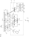
- the scanning beam path in the first exemplary embodiment will now be explained below, via which a plurality of phase-shifted distance signals S0, S120, S240 with respect to the distance zP or with respect to changes in the distance zP between the two plates 1, 2 are generated.
- the radiation beam emitted by a light source 3.1 in the scanning unit 3 strikes, at an angle ⁇ inclined relative to the optical axis A, on a beam splitter element 1.2 on the first plate 1.
- the light source 3.1 is preferably a laser emitting a linearly polarized beam.
- the beam splitter element 1.2 is formed in the present example as a planar beam splitter layer, which is arranged on that side of the first plate 1, which is oriented away from the light source 3.1; This page will be referred to below as the top of the first plate 1.
- the beam bundle incident from the light source 3.1 undergoes a division into two partial beams, one of which is reflected and another is transmitted.
- the reflected partial beam is subsequently referred to as a reference beam R
- the designation of the two split radiation beams as measurement and reference beams M, R is arbitrary and of course the designations could be chosen the other way around as well.
- the measuring beam M subsequently impinges on the first plate 1 nominally parallel second plate 2.
- a reflector element 2.2 is arranged on the first plate 1 facing side of the second plate 2, hereinafter also referred to as the underside of the second plate 2.
- the reflector element 2.2 is designed as a planar mirror layer whose reflective side is oriented in the direction of the first plate 1.
- the measuring beam M undergoes a first return reflection in the direction of the first plate 1.
- the measuring beam M then passes through the first plate 1 in a transparent, optically ineffective region, passes through a polarization-optical element 3.2b, formed as ⁇ / 8-plate, and then passes to a scanning 3.3 in the scanning unit 3.
- the measuring beam M passes through a first deflecting element, an associated retroreflector and a fourth deflecting element before it propagates again in the direction of the two plates 1, 2.
- the incident from the direction of the two plates 1, 2 forth measuring beam M first passes through a deflection AE, which is designed as a grid.
- the incident under the angle of incidence ⁇ in the optical axis A incident beam M is deflected by the deflection element AE such that it propagates after passing through desselbigen parallel to the optical axis A in the direction of a retroreflector RR.
- the retroreflector RR consists in the example shown from a diffractive lens DL and a reflector element R, formed as a mirror layer; Preferably, the diffractive lens DL and the reflector element R are arranged on the opposite sides of a plate-shaped, transparent support member.
- the diffractive lens DL the measuring beam M is focused on the reflector element R; from the reflector element R results in a back reflection in the direction of the diffractive lens DL, which collapses the emergent measuring beam M again, before it again meets the deflector AE.
- the deflecting element AE and / or the diffractive lens DL of the retroreflector RR can in principle also be designed in several parts, that is to say, for example. in each case only in the region of the incoming and outgoing measuring beam M.
- the deflection element AE deflects the measurement beam M, M 'differently during the first and second passes. That's how it turns out FIG. 3 the incident measuring beam M, M 'in +1. Distracted diffraction order, the failed measuring beam M but in -1. Diffraction order.
- the combined diffractive deflection lens element is arranged on one side of a plate-shaped, transparent carrier element, on the opposite side of the reflector element, wherein the reflective side is oriented towards the other side.
- a second combined, diffractive deflection lens element 3.4b is arranged on the side of the scanning plate 3.3, which faces the two plates 1, 2. This deflects the measuring beam M via the corresponding optical deflection function parallel to the optical axis A and focuses it simultaneously on its optical lens function on a reflector element 3.5 on the opposite side of the scanning 3.3. There, the measuring beam M impinges on the reflector element 3.5 in the region of the optical axis A, is reflected thereby and reaches a third combined, diffractive deflection lens element 3.4c.
- the third combined, diffractive deflection lens element 3.4c and its optical lens function results in a collimation of the measurement beam M, via the optical deflection function of the third combined diffractive deflection lens element 3.4c deflects the measurement beam M towards the optical axis A at an angle ⁇ .
- the measuring beam M propagating in the direction of the two plates 1, 2 first passes through another polarization-optical element 3.2c, again formed as ⁇ / 8 plate, then passes through a transparent region of the plate 1 and finally meets the reflector element 2.2 on the second There it then experiences a second return reflection, then passes through a further beam splitter element 1.3 on the first plate 1 and propagates in the direction of a detection unit 4th
- the reference beam R generated at the beam splitter element 1.2 of the first plate 1 is reflected back in the direction of the scanning unit 3 and passes there through a polarization-optical element 3.2a in the form of a ⁇ / 8 plate and reaches a first combined, diffractive deflection lens element 3.4a, which on the same side of the scanning 3.3 is arranged as the second, by the measuring beam M passed through combined diffractive deflection lens element 3.4b.
- the first combined diffractive deflection lens element 3.4a performs a basically comparable optical function as the second combined diffractive deflection lens element 3.4b on the measurement beam M.
- the optical deflection function of the first combined, diffractive Deflection lens element 3.4a the reference sub-beam R is aligned parallel to the optical axis A, while it is focused on the optical lens function on the reflector element 3.5 in the region of the optical axis A on the reflector element 3.6, which is arranged on the side of the scanning 3.3, the the two plates 1, 2 faces.
- the reference beam R then passes via a further reflection on the reflector element 3.5 to the fourth combined, diffractive deflection lens element 3.4d. This collimates the reference beam R again and also deflects it at an angle ⁇ to the optical axis A down.
- the reference beam R thus passes through a first deflection element, an associated retroreflector and a fourth deflection element before it propagates again in the direction of the two plates 1, 2.
- a polarization-optical element 3.2d designed as ⁇ / 8 the reference beam R then passes onto the beam splitter element 1.3 on the first plate 1, where it is superimposed with the measuring beam M also arriving there and propagates in the direction of the detection unit 4 after further reflection ,
- the reference beam R in the present embodiment in the scanning 3.3 traversed due to the additional reflection on the reflector element 3.6 is preferably chosen so that it is equal to the additional optical path of the measuring beam M between the in the nominal position of the plates 1, 2 Plates 1, 2 is.
- the optical path lengths of the two beams are thus compensated in the nominal position. This results in a particularly low position noise, since the phase noise of the light source 3.1 in this nominal position has no influence.
- a short coherence length light source 3.1 can be used, which substantially reduces interference from unwanted noise (e.g., by "speckle" on housing walls).
- the measurement and reference beams M, R are circularly polarized relative to each other by suitably oriented polarization-optical components 3.2a-3.2d, each formed as ⁇ / 8 platelets.
- a splitting grating 4.1 in the detection unit 4 splits the two collinear measuring and reference beams M, R into three further ones Partial beam on. These pass through respective polarizers 4.2a, 4.2b, 4.2c before they are converted by optoelectronic detector elements 4.3a, 4.3b, 4.3c into phase-shifted, electrical distance signals S0, S120, S240.
- the polarizers 4.2a, 4.2b, 4.2c are oriented at an angle of 60 ° to one another, so that a phase shift of 120 ° in each case results between the generated distance signals S0, S120, S240.
- all the radiation beams from the light source 3.1 to the detection unit 4 extend in one plane, namely in the one in FIG Fig. 1a displayed XZ plane.
- the effective measuring point for each of the two plates 1, 2 lies on the optical axis A between the points of impact of the corresponding partial beams M, R.
- the effective measuring point for the second plate is located at location 2.1 on the underside of the plate 2; for the first plate 1, the effective measuring point is located at the location 1.1 on the upper side of the plate 1.
- the measuring points 1.1, 2.1 remain even with a z-displacement of the first plate 1 on the optical axis A lying.
- an additional optical position measuring device which in the FIGS. 1a . 1b is not shown, can - as already mentioned above - also a lateral displacement of the two plates 1, 2 are detected in the xy plane to each other.
- Both plates 1, 2 can for this purpose have at the measuring points 1.1, 2.1 grating structures which are scanned by a suitable scanning head.
- the scanning of a scanning optics such as from the DE 10 2010 043 263 is known, is arranged in the scanning unit 3 preferably in the vicinity of the optical axis A and also has effective measuring points at the locations 1.1, 2.1. on.
- Common measuring points 1.1, 2.1 of the inventive device for interferometric distance determination and an additional optical position measuring device allow a particularly favorable evaluation of the distance signals generated with a simple determination of several degrees of freedom.
- the 6D pose can be used to calculate the relative position of the plates 1, 2 or associated machine parts at the location of a Tool Center Point (TCP), thus correcting any abbe errors.
- TCP Tool Center Point
- the first plate 1 is provided on the upper side outside the areas with the beam splitter elements 1.2, 1.3 and on the entire bottom with an antireflection layer. Also advantageous is the arrangement of a diaphragm (not shown in the figures) in front of the detection unit 4 or in the area in which the collinearly superimposed measuring and reference beams M, R propagate in the direction of the detection unit 4, in order to suppress disturbing reflections. It is also favorable to make the first plate 1 slightly wedge-shaped in order to avoid interference with multiple reflections within this plate 1.
- FIGS. 4a . 4b . 5 and 6a and 6b show the beam path or parts thereof in different views analogously to the first embodiment in schematic form
- FIG. 5 a plan view of the top of the scanning
- FIG. 6a and 6b Views of the first and second plate of the device according to the invention.
- the second exemplary embodiment of a device according to the invention differs from the first embodiment primarily in that the beam path from the light source 13.1 to the detection unit 14 no longer extends completely in one plane, as was the case in the xz plane in the first example.
- the light source 13.1 is arranged in this embodiment in the y-direction offset from the optical axis A and emits a beam at the inclination angle ⁇ to the optical axis A parallel to the xz-plane.
- the reference beam R and the measuring beam M hit in the y-direction offset to the associated first and second combined diffractive deflection lens elements 13.4a, 13.4b on the top of the scanning 13.3 in the scanning unit 13.
- Their lens functions are chosen in this embodiment so that both the reference beam R and the measuring beam M are focused on the reflector element 13.5 on the underside of the scanning 13.3, seen laterally, the focus location is again on the optical axis A. Symmetrical to the optical axis A.
- FIGS. 4a . 4b and FIGS. 6a, 6b show components of such an optical position-measuring device in a highly schematic manner.
- These include a scanning unit 20 assigned to the scanning unit 13 and a first measuring graduation 21 on the first plate 11 and a second measuring graduation 22 on the second plate 12.
- the first measuring graduation 21 is in this case arranged centrally between the two beam splitter elements 11.2, 11.3 of the first plate 11, the second measuring standard 22 in the middle between the two reflector elements 12.2, 12.3 of the second plate 12.
- the scanning head 20 may comprise approximately a light source and a detector unit; as the first and second measuring graduation 21, 22, an incremental graduation extending in the x-direction is provided in each case.
- baffles may serve as grating, prisms or mirrors
- the lenses may be made diffractive or refractive.
- the retroreflector functionality via triple mirrors or triple prisms, i. the diffractive or refractive lens, the associated mirror and the subsequent diffractive or refractive lens could also be replaced by a triple prism or a triple mirror.
- the coherence length of the light source is chosen to be so short that disruptive multiple reflections on the two plates are no longer capable of interfering.
- phase-shifted distance signals starting from mutually orthogonally polarized beam bundles can be carried out in an alternative manner as described in the two embodiments.
- the tilt of the two interfering beams could also be achieved by slightly varying the deflection angles of the combined diffractive deflection lens elements for the measuring and reference beams.
Landscapes
- Physics & Mathematics (AREA)
- General Physics & Mathematics (AREA)
- Length Measuring Devices By Optical Means (AREA)
- Optical Transform (AREA)
- Instruments For Measurement Of Length By Optical Means (AREA)
Claims (13)
- Arrangement de détermination interférométrique de la distance entre deux plaques (1, 2 ; 11, 12) disposées largement en parallèle, comprenant une source de lumière (3.1 ; 13.1), au moins un élément séparateur de faisceau (1.2 ; 11.2), au moins un élément réflecteur (2.2, 3.5, 3.6 ; 12.1, 12.2, 13.5), plusieurs éléments de déviation, plusieurs rétroréflecteurs (RR) et une unité de détection (4 ; 14), la source de lumière, l'au moins un élément séparateur de faisceau, l'au moins un élément réflecteur, les plusieurs éléments de déviation, les plusieurs réflecteurs et l'unité de détection étant disposés de telle sorte que :- un faisceau de rayons émis par la source de lumière (3.1 ; 13.1) venant frapper en biais un élément séparateur de faisceau (1.2 ; 11.2) sur la première plaque (1 ; 11) et y subit une dissociation en un faisceau de rayons de référence (R) réfléchi et un faisceau de rayons de mesure (M) transmis et- le faisceau de rayons de mesure (M) vient frapper un élément réflecteur (2.2 ; 12.2) sur la deuxième plaque (2) et y subit une première rétroréflexion en direction de la première plaque (1) et- le faisceau de rayons de référence (R) traverse un premier élément de déviation et le faisceau de rayons de mesure (M) un deuxième élément de déviation, les faisceaux de rayons de mesure et de référence (M, R) traversent ensuite respectivement un rétroréflecteur (RR) associé et ensuite le faisceau de rayons de mesure (M) traverse un troisième élément de déviation et le faisceau de rayons de référence (R) un quatrième élément de déviation, les premier et deuxième éléments de déviation ainsi que les troisième et quatrième éléments de déviation exerçant respectivement des effets de déviation différents sur les faisceaux de rayons de mesure et de référence (M, R) traversants et- le faisceau de rayons de référence (R) subit alors une réflexion au niveau de la première plaque (1 ; 11) et- le faisceau de rayons de mesure (M) subit ensuite une deuxième rétroréflexion au niveau d'un élément réflecteur (2.2 ; 12.3) de la deuxième plaque (2 ; 12), de sorte que :- le faisceau de rayons de mesure (M) et le faisceau de rayons de référence (R) se propagent alors de manière colinéaire en direction de l'unité de détection (4 ; 14) où plusieurs signaux de distance (S0, S120, S240) déphasés peuvent être générés à partir des faisceaux de rayons de mesure et de référence (M, R) interférents.
- Arrangement selon la revendication 1, les rétroréflecteurs (RR) comportant une première lentille diffractive (DL), un élément réflecteur (R) et une deuxième lentille diffractive (DL), la première lentille diffractive (DL) effectuant une concentration, sur l'élément réflecteur (R), du faisceau de rayons de référence ou de mesure (R, M) incident sur celle-ci et la deuxième lentille diffractive (DL) effectuant une collimation du faisceau de rayons de référence ou de mesure (R, M) émergeant, réfléchi par l'élément réflecteur (R).
- Arrangement selon la revendication 2, la première et la deuxième lentille diffractive (DL) étant disposées sur un premier côté d'un élément porteur transparent en forme de plaque et l'élément réflecteur (R), dont le côté réfléchissant est orienté en direction du premier côté, étant disposé sur le deuxième côté opposé de l'élément porteur.
- Arrangement selon la revendication 2,- le premier élément de déviation et la première lentille diffractive ainsi que le quatrième élément de déviation et la deuxième lentille diffractive d'un premier rétroréflecteur étant réalisés sous la forme d'un premier et quatrième élément formant lentille de déviation diffractif combiné (3.2a, 3.2d ; 13.2a, 13.2d) et- le deuxième élément de déviation et la première lentille diffractive ainsi que le troisième élément de déviation et la deuxième lentille diffractive d'un deuxième rétroréflecteur étant réalisés sous la forme d'un deuxième et troisième élément formant lentille de déviation diffractif combiné (3.2b, 3.2c ; 13.2b, 13.2c).
- Arrangement selon la revendication 4, les éléments formant lentille de déviation diffractifs combinés (3.2a, 3.2b, 3.2c, 3.2d ; 13.2a, 13.2b, 13.2c, 13.2d) étant disposés sur un premier côté d'un élément porteur transparent en forme de plaque et l'élément réflecteur (3.5 ; 13.5), dont le côté réfléchissant est orienté en direction du premier côté, étant disposé sur le deuxième côté opposé de l'élément porteur.
- Arrangement selon au moins l'une des revendications précédentes, les longueurs de trajet optiques des faisceaux de rayons de mesure et de référence (M, R) étant identiques dans une position nominale définie.
- Arrangement selon la revendication 6, les rétroréflecteurs respectivement associés aux faisceaux de rayons de mesure et de référence (M, R) étant de configuration différente en vue du réglage de longueurs de trajet optique identiques.
- Arrangement selon au moins l'une des revendications précédentes, l'équation suivante étant vérifiée pour l'angle (θ) sous lequel le faisceau de rayons émis par la source de lumière (3.1 ; 13.1) est incident sur la première plaque en biais :
 θ désigne l'angle par rapport à une verticale sur la première plaque, sous lequel le faisceau de rayons émis par la source de lumière est incident sur la première plaque,rS désigne le rayon de rayonnement de la source de lumière zP désigne la distance entre la première et la deuxième plaque.
 - Arrangement selon au moins l'une des revendications précédentes, la première plaque (1 ; 11) étant réalisée sous la forme d'une plaque plane transparente,- sur le côté à l'opposé de la source de lumière (3.1 ; 13.1) de laquelle est disposée, en tant qu'élément séparateur de faisceau (1.2 ; 11.2) dans une première zone délimitée dans l'espace, une couche de séparation de faisceau plane sur laquelle vient frapper le faisceau de rayons émis par la source de lumière (3.1 ; 13.1) et- sur le même côté est disposée, en tant qu'élément séparateur de faisceau supplémentaire (1.3 ; 11.3) dans une deuxième zone délimitée dans l'espace, une couche de séparation de faisceau plane supplémentaire sur laquelle vient frapper le faisceau de rayons de mesure (M) après la deuxième rétroréflexion au niveau de l'élément réflecteur (2.2 ; 12.3) de la deuxième plaque (2) et sur laquelle vient frapper le faisceau de rayons de référence (R) après avoir traversé le quatrième élément de déviation.
- Arrangement selon la revendication 9, la première plaque (1 ; 11) possédant une couche antiréfléchissante sur le côté faisant face à la source de lumière (3.1 ; 13.1) ainsi que sur le côté opposé en-dehors des zones comportant les éléments séparateurs de faisceau (1.2, 1.3 ; 11.2, 11.3) et/ou possédant un obturateur dans la zone dans laquelle les faisceaux de rayons de mesure et de référence (M, R) superposés de manière colinéaire se propagent en direction de l'unité de détection (4 ; 14).
- Arrangement selon au moins l'une des revendications précédentes, la deuxième plaque (2 ; 12) étant réalisée sous la forme d'une plaque plane transparente sur le côté faisant face à la source de lumière (3.1 ; 13.1) de laquelle sont disposées, en tant qu'éléments réflecteurs (2.2 ; 12.2, 12.3), des couches réfléchissantes planes dont les côtés réfléchissants sont orientés en direction de la première plaque (1 ; 11).
- Système, constitué d'un arrangement selon au moins l'une des revendications précédentes combiné avec un dispositif de mesure de position optique, qui est adapté pour détecter un décalage relatif de la première et de la deuxième plaque (1, 2 ; 11, 12) parallèlement aux plans de disposition des deux plaques (1, 2 ; 11, 12) .
- Système selon la revendication 12, les points de mesure (1.1, 2.1 ; 11.1, 12.1) du dispositif de mesure de position optique et de l'arrangement de détermination interférométrique de la distance étant coïncidents.
Applications Claiming Priority (1)
| Application Number | Priority Date | Filing Date | Title |
|---|---|---|---|
| DE102011111900A DE102011111900A1 (de) | 2011-08-30 | 2011-08-30 | Vorrichtung zur interferometrischen Abstandsbestimmung |
Publications (2)
| Publication Number | Publication Date |
|---|---|
| EP2565578A1 EP2565578A1 (fr) | 2013-03-06 |
| EP2565578B1 true EP2565578B1 (fr) | 2018-12-19 |
Family
ID=46682673
Family Applications (1)
| Application Number | Title | Priority Date | Filing Date |
|---|---|---|---|
| EP12177860.9A Active EP2565578B1 (fr) | 2011-08-30 | 2012-07-25 | Dispositif interférométrique de détermination de distance entre deux plaques parallèles |
Country Status (5)
| Country | Link |
|---|---|
| US (1) | US9068811B2 (fr) |
| EP (1) | EP2565578B1 (fr) |
| JP (1) | JP6063166B2 (fr) |
| CN (1) | CN102967269B (fr) |
| DE (1) | DE102011111900A1 (fr) |
Families Citing this family (7)
| Publication number | Priority date | Publication date | Assignee | Title |
|---|---|---|---|---|
| DE102011076178B4 (de) * | 2011-05-20 | 2022-03-31 | Dr. Johannes Heidenhain Gmbh | Positionsmesseinrichtung |
| DE102013206693A1 (de) | 2013-04-15 | 2014-10-16 | Dr. Johannes Heidenhain Gmbh | Vorrichtung zur interferentiellen Abstandsmessung |
| DE102013211758A1 (de) * | 2013-06-21 | 2014-12-24 | Dr. Johannes Heidenhain Gmbh | Interferometer |
| DE102014208988A1 (de) * | 2013-09-11 | 2015-03-12 | Dr. Johannes Heidenhain Gmbh | Optische Positionsmesseinrichtung |
| DE102013221898A1 (de) * | 2013-10-29 | 2015-04-30 | Dr. Johannes Heidenhain Gmbh | Vorrichtung zur Positionsbestimmung |
| DE102017201257A1 (de) * | 2017-01-26 | 2018-07-26 | Dr. Johannes Heidenhain Gmbh | Positionsmesseinrichtung |
| CN109945783B (zh) * | 2019-03-13 | 2020-11-17 | 北京交通大学 | 基于夫琅禾费衍射的微距测量方法 |
Family Cites Families (15)
| Publication number | Priority date | Publication date | Assignee | Title |
|---|---|---|---|---|
| JPS5174659A (fr) * | 1974-12-24 | 1976-06-28 | Nippon Electric Co | |
| US4606638A (en) * | 1983-11-03 | 1986-08-19 | Zygo Corporation | Distance measuring interferometer and method of use |
| JPS6065626U (ja) * | 1984-08-30 | 1985-05-09 | 日本電気株式会社 | 変位測定装置 |
| JP3478567B2 (ja) * | 1992-09-25 | 2003-12-15 | キヤノン株式会社 | 回転情報検出装置 |
| CN1131741A (zh) * | 1995-03-22 | 1996-09-25 | 载歌公司 | 光学间隙测量装置和方法 |
| JP2000136998A (ja) * | 1998-11-02 | 2000-05-16 | Central Glass Co Ltd | 雨滴検出装置 |
| EP0999104A3 (fr) * | 1998-11-02 | 2003-09-17 | Central Glass Company, Limited | Capteur de pluie et système d'exposition pour hologramme |
| DE10333772A1 (de) * | 2002-08-07 | 2004-02-26 | Dr. Johannes Heidenhain Gmbh | Interferenzielle Positionsmesseinrichtung |
| EP1664932B1 (fr) * | 2003-09-15 | 2015-01-28 | Zygo Corporation | Procedes et systemes d'analyse interferometrique de surfaces et applications associees |
| JP4514209B2 (ja) * | 2004-10-15 | 2010-07-28 | キヤノン株式会社 | 位置検出装置及び方法 |
| DE102005043569A1 (de) * | 2005-09-12 | 2007-03-22 | Dr. Johannes Heidenhain Gmbh | Positionsmesseinrichtung |
| DE102007016774A1 (de) | 2007-04-04 | 2008-10-09 | Friedrich-Schiller-Universität Jena | Verfahren und Vorrichtung zur interferenziellen Abstandsmessung von Objekten |
| DE102007023300A1 (de) * | 2007-05-16 | 2008-11-20 | Dr. Johannes Heidenhain Gmbh | Positionsmesseinrichtung und Anordnung derselben |
| DE102008007319A1 (de) | 2008-02-02 | 2009-08-06 | Dr. Johannes Heidenhain Gmbh | Optische Positionsmesseinrichtung |
| DE102011081879A1 (de) | 2010-11-03 | 2012-05-03 | Dr. Johannes Heidenhain Gmbh | Optische Winkelmesseinrichtung |
-
2011
- 2011-08-30 DE DE102011111900A patent/DE102011111900A1/de not_active Withdrawn
-
2012
- 2012-07-25 EP EP12177860.9A patent/EP2565578B1/fr active Active
- 2012-08-02 JP JP2012171642A patent/JP6063166B2/ja active Active
- 2012-08-28 US US13/596,836 patent/US9068811B2/en active Active
- 2012-08-30 CN CN201210317094.6A patent/CN102967269B/zh active Active
Non-Patent Citations (1)
| Title |
|---|
| None * |
Also Published As
| Publication number | Publication date |
|---|---|
| US9068811B2 (en) | 2015-06-30 |
| JP6063166B2 (ja) | 2017-01-18 |
| US20130057872A1 (en) | 2013-03-07 |
| CN102967269A (zh) | 2013-03-13 |
| DE102011111900A1 (de) | 2013-02-28 |
| EP2565578A1 (fr) | 2013-03-06 |
| CN102967269B (zh) | 2016-08-03 |
| JP2013050448A (ja) | 2013-03-14 |
Similar Documents
| Publication | Publication Date | Title |
|---|---|---|
| EP2565578B1 (fr) | Dispositif interférométrique de détermination de distance entre deux plaques parallèles | |
| EP1319170B1 (fr) | Dispositif de mesure de position | |
| EP1901041B1 (fr) | Dispositif de mesure de position | |
| EP1739395B1 (fr) | Dispositif de mesure de position | |
| EP2474815B1 (fr) | Dispositif optique de mesure de la position | |
| EP2388558B1 (fr) | Dispositif optique de mesure de la position | |
| EP2848899B1 (fr) | Dispositif optique de mesure de position | |
| DE102009028068B4 (de) | Positionsmessvorrichtung | |
| EP2857802B1 (fr) | Dispositif optique de mesure de position | |
| EP2149029A1 (fr) | Dispositif de mesure de position | |
| EP2623937B1 (fr) | Dispositif de mesure de position et agencement à plusieurs dispositifs de mesure de position | |
| EP2674720B1 (fr) | Dispositif de mesure de distance interférentielle | |
| DE102010003157A1 (de) | Vorrichtung zur interferentiellen Abstandsmessung | |
| EP3059554B1 (fr) | Dispositif optique de mesure de position | |
| EP2980525B1 (fr) | Interferometre à triple passage | |
| DE102011076178B4 (de) | Positionsmesseinrichtung | |
| DE102018000887A1 (de) | Vorrichtung und ein Verfahren zum Durchführen und Überwachen eines Bearbeitungsprozesses auf einem Werkstück mit der Möglichkeit zur OCT-Scanner-Kalibrierung | |
| EP2816316B1 (fr) | Interféromètre | |
| EP2955489A1 (fr) | Dispositif optique de mesure de position | |
| EP2746731B1 (fr) | Dispositif optique de mesure de la position | |
| DE102011077376A1 (de) | Optische Abstandsmessvorrichtung | |
| DE102011005937B4 (de) | Vorrichtung zur interferentiellen Abstandsmessung | |
| EP3045873B1 (fr) | Dispositif optique de mesure de position | |
| EP2869034A1 (fr) | Dispositif de détermination de la position | |
| DE112014001977B4 (de) | Vorrichtung zur interferentiellen Abstandsmessung |
Legal Events
| Date | Code | Title | Description |
|---|---|---|---|
| PUAI | Public reference made under article 153(3) epc to a published international application that has entered the european phase |
Free format text: ORIGINAL CODE: 0009012 |
|
| AK | Designated contracting states |
Kind code of ref document: A1 Designated state(s): AL AT BE BG CH CY CZ DE DK EE ES FI FR GB GR HR HU IE IS IT LI LT LU LV MC MK MT NL NO PL PT RO RS SE SI SK SM TR |
|
| AX | Request for extension of the european patent |
Extension state: BA ME |
|
| RIN1 | Information on inventor provided before grant (corrected) |
Inventor name: HOLZAPFEL, WOLFGANG |
|
| 17P | Request for examination filed |
Effective date: 20130906 |
|
| RBV | Designated contracting states (corrected) |
Designated state(s): AL AT BE BG CH CY CZ DE DK EE ES FI FR GB GR HR HU IE IS IT LI LT LU LV MC MK MT NL NO PL PT RO RS SE SI SK SM TR |
|
| GRAP | Despatch of communication of intention to grant a patent |
Free format text: ORIGINAL CODE: EPIDOSNIGR1 |
|
| STAA | Information on the status of an ep patent application or granted ep patent |
Free format text: STATUS: GRANT OF PATENT IS INTENDED |
|
| INTG | Intention to grant announced |
Effective date: 20180907 |
|
| GRAS | Grant fee paid |
Free format text: ORIGINAL CODE: EPIDOSNIGR3 |
|
| GRAA | (expected) grant |
Free format text: ORIGINAL CODE: 0009210 |
|
| STAA | Information on the status of an ep patent application or granted ep patent |
Free format text: STATUS: THE PATENT HAS BEEN GRANTED |
|
| AK | Designated contracting states |
Kind code of ref document: B1 Designated state(s): AL AT BE BG CH CY CZ DE DK EE ES FI FR GB GR HR HU IE IS IT LI LT LU LV MC MK MT NL NO PL PT RO RS SE SI SK SM TR |
|
| REG | Reference to a national code |
Ref country code: GB Ref legal event code: FG4D Free format text: NOT ENGLISH |
|
| REG | Reference to a national code |
Ref country code: CH Ref legal event code: EP |
|
| REG | Reference to a national code |
Ref country code: IE Ref legal event code: FG4D Free format text: LANGUAGE OF EP DOCUMENT: GERMAN |
|
| REG | Reference to a national code |
Ref country code: DE Ref legal event code: R096 Ref document number: 502012013998 Country of ref document: DE |
|
| REG | Reference to a national code |
Ref country code: AT Ref legal event code: REF Ref document number: 1079197 Country of ref document: AT Kind code of ref document: T Effective date: 20190115 |
|
| REG | Reference to a national code |
Ref country code: NL Ref legal event code: FP |
|
| PG25 | Lapsed in a contracting state [announced via postgrant information from national office to epo] |
Ref country code: NO Free format text: LAPSE BECAUSE OF FAILURE TO SUBMIT A TRANSLATION OF THE DESCRIPTION OR TO PAY THE FEE WITHIN THE PRESCRIBED TIME-LIMIT Effective date: 20190319 Ref country code: LT Free format text: LAPSE BECAUSE OF FAILURE TO SUBMIT A TRANSLATION OF THE DESCRIPTION OR TO PAY THE FEE WITHIN THE PRESCRIBED TIME-LIMIT Effective date: 20181219 Ref country code: BG Free format text: LAPSE BECAUSE OF FAILURE TO SUBMIT A TRANSLATION OF THE DESCRIPTION OR TO PAY THE FEE WITHIN THE PRESCRIBED TIME-LIMIT Effective date: 20190319 Ref country code: FI Free format text: LAPSE BECAUSE OF FAILURE TO SUBMIT A TRANSLATION OF THE DESCRIPTION OR TO PAY THE FEE WITHIN THE PRESCRIBED TIME-LIMIT Effective date: 20181219 Ref country code: LV Free format text: LAPSE BECAUSE OF FAILURE TO SUBMIT A TRANSLATION OF THE DESCRIPTION OR TO PAY THE FEE WITHIN THE PRESCRIBED TIME-LIMIT Effective date: 20181219 Ref country code: HR Free format text: LAPSE BECAUSE OF FAILURE TO SUBMIT A TRANSLATION OF THE DESCRIPTION OR TO PAY THE FEE WITHIN THE PRESCRIBED TIME-LIMIT Effective date: 20181219 |
|
| REG | Reference to a national code |
Ref country code: LT Ref legal event code: MG4D |
|
| PG25 | Lapsed in a contracting state [announced via postgrant information from national office to epo] |
Ref country code: SE Free format text: LAPSE BECAUSE OF FAILURE TO SUBMIT A TRANSLATION OF THE DESCRIPTION OR TO PAY THE FEE WITHIN THE PRESCRIBED TIME-LIMIT Effective date: 20181219 Ref country code: AL Free format text: LAPSE BECAUSE OF FAILURE TO SUBMIT A TRANSLATION OF THE DESCRIPTION OR TO PAY THE FEE WITHIN THE PRESCRIBED TIME-LIMIT Effective date: 20181219 Ref country code: GR Free format text: LAPSE BECAUSE OF FAILURE TO SUBMIT A TRANSLATION OF THE DESCRIPTION OR TO PAY THE FEE WITHIN THE PRESCRIBED TIME-LIMIT Effective date: 20190320 Ref country code: RS Free format text: LAPSE BECAUSE OF FAILURE TO SUBMIT A TRANSLATION OF THE DESCRIPTION OR TO PAY THE FEE WITHIN THE PRESCRIBED TIME-LIMIT Effective date: 20181219 |
|
| PG25 | Lapsed in a contracting state [announced via postgrant information from national office to epo] |
Ref country code: PL Free format text: LAPSE BECAUSE OF FAILURE TO SUBMIT A TRANSLATION OF THE DESCRIPTION OR TO PAY THE FEE WITHIN THE PRESCRIBED TIME-LIMIT Effective date: 20181219 Ref country code: IT Free format text: LAPSE BECAUSE OF FAILURE TO SUBMIT A TRANSLATION OF THE DESCRIPTION OR TO PAY THE FEE WITHIN THE PRESCRIBED TIME-LIMIT Effective date: 20181219 Ref country code: PT Free format text: LAPSE BECAUSE OF FAILURE TO SUBMIT A TRANSLATION OF THE DESCRIPTION OR TO PAY THE FEE WITHIN THE PRESCRIBED TIME-LIMIT Effective date: 20190419 Ref country code: CZ Free format text: LAPSE BECAUSE OF FAILURE TO SUBMIT A TRANSLATION OF THE DESCRIPTION OR TO PAY THE FEE WITHIN THE PRESCRIBED TIME-LIMIT Effective date: 20181219 Ref country code: ES Free format text: LAPSE BECAUSE OF FAILURE TO SUBMIT A TRANSLATION OF THE DESCRIPTION OR TO PAY THE FEE WITHIN THE PRESCRIBED TIME-LIMIT Effective date: 20181219 |
|
| PG25 | Lapsed in a contracting state [announced via postgrant information from national office to epo] |
Ref country code: RO Free format text: LAPSE BECAUSE OF FAILURE TO SUBMIT A TRANSLATION OF THE DESCRIPTION OR TO PAY THE FEE WITHIN THE PRESCRIBED TIME-LIMIT Effective date: 20181219 Ref country code: IS Free format text: LAPSE BECAUSE OF FAILURE TO SUBMIT A TRANSLATION OF THE DESCRIPTION OR TO PAY THE FEE WITHIN THE PRESCRIBED TIME-LIMIT Effective date: 20190419 Ref country code: EE Free format text: LAPSE BECAUSE OF FAILURE TO SUBMIT A TRANSLATION OF THE DESCRIPTION OR TO PAY THE FEE WITHIN THE PRESCRIBED TIME-LIMIT Effective date: 20181219 Ref country code: SM Free format text: LAPSE BECAUSE OF FAILURE TO SUBMIT A TRANSLATION OF THE DESCRIPTION OR TO PAY THE FEE WITHIN THE PRESCRIBED TIME-LIMIT Effective date: 20181219 Ref country code: SK Free format text: LAPSE BECAUSE OF FAILURE TO SUBMIT A TRANSLATION OF THE DESCRIPTION OR TO PAY THE FEE WITHIN THE PRESCRIBED TIME-LIMIT Effective date: 20181219 |
|
| REG | Reference to a national code |
Ref country code: DE Ref legal event code: R097 Ref document number: 502012013998 Country of ref document: DE |
|
| PLBE | No opposition filed within time limit |
Free format text: ORIGINAL CODE: 0009261 |
|
| STAA | Information on the status of an ep patent application or granted ep patent |
Free format text: STATUS: NO OPPOSITION FILED WITHIN TIME LIMIT |
|
| PG25 | Lapsed in a contracting state [announced via postgrant information from national office to epo] |
Ref country code: DK Free format text: LAPSE BECAUSE OF FAILURE TO SUBMIT A TRANSLATION OF THE DESCRIPTION OR TO PAY THE FEE WITHIN THE PRESCRIBED TIME-LIMIT Effective date: 20181219 |
|
| 26N | No opposition filed |
Effective date: 20190920 |
|
| PG25 | Lapsed in a contracting state [announced via postgrant information from national office to epo] |
Ref country code: MC Free format text: LAPSE BECAUSE OF FAILURE TO SUBMIT A TRANSLATION OF THE DESCRIPTION OR TO PAY THE FEE WITHIN THE PRESCRIBED TIME-LIMIT Effective date: 20181219 Ref country code: SI Free format text: LAPSE BECAUSE OF FAILURE TO SUBMIT A TRANSLATION OF THE DESCRIPTION OR TO PAY THE FEE WITHIN THE PRESCRIBED TIME-LIMIT Effective date: 20181219 |
|
| REG | Reference to a national code |
Ref country code: CH Ref legal event code: PL |
|
| GBPC | Gb: european patent ceased through non-payment of renewal fee |
Effective date: 20190725 |
|
| PG25 | Lapsed in a contracting state [announced via postgrant information from national office to epo] |
Ref country code: TR Free format text: LAPSE BECAUSE OF FAILURE TO SUBMIT A TRANSLATION OF THE DESCRIPTION OR TO PAY THE FEE WITHIN THE PRESCRIBED TIME-LIMIT Effective date: 20181219 |
|
| REG | Reference to a national code |
Ref country code: BE Ref legal event code: MM Effective date: 20190731 |
|
| PG25 | Lapsed in a contracting state [announced via postgrant information from national office to epo] |
Ref country code: GB Free format text: LAPSE BECAUSE OF NON-PAYMENT OF DUE FEES Effective date: 20190725 |
|
| PG25 | Lapsed in a contracting state [announced via postgrant information from national office to epo] |
Ref country code: BE Free format text: LAPSE BECAUSE OF NON-PAYMENT OF DUE FEES Effective date: 20190731 Ref country code: LU Free format text: LAPSE BECAUSE OF NON-PAYMENT OF DUE FEES Effective date: 20190725 Ref country code: LI Free format text: LAPSE BECAUSE OF NON-PAYMENT OF DUE FEES Effective date: 20190731 Ref country code: CH Free format text: LAPSE BECAUSE OF NON-PAYMENT OF DUE FEES Effective date: 20190731 |
|
| PG25 | Lapsed in a contracting state [announced via postgrant information from national office to epo] |
Ref country code: FR Free format text: LAPSE BECAUSE OF NON-PAYMENT OF DUE FEES Effective date: 20190731 |
|
| PG25 | Lapsed in a contracting state [announced via postgrant information from national office to epo] |
Ref country code: IE Free format text: LAPSE BECAUSE OF NON-PAYMENT OF DUE FEES Effective date: 20190725 |
|
| REG | Reference to a national code |
Ref country code: AT Ref legal event code: MM01 Ref document number: 1079197 Country of ref document: AT Kind code of ref document: T Effective date: 20190725 |
|
| PG25 | Lapsed in a contracting state [announced via postgrant information from national office to epo] |
Ref country code: AT Free format text: LAPSE BECAUSE OF NON-PAYMENT OF DUE FEES Effective date: 20190725 |
|
| PG25 | Lapsed in a contracting state [announced via postgrant information from national office to epo] |
Ref country code: CY Free format text: LAPSE BECAUSE OF FAILURE TO SUBMIT A TRANSLATION OF THE DESCRIPTION OR TO PAY THE FEE WITHIN THE PRESCRIBED TIME-LIMIT Effective date: 20181219 |
|
| PG25 | Lapsed in a contracting state [announced via postgrant information from national office to epo] |
Ref country code: MT Free format text: LAPSE BECAUSE OF FAILURE TO SUBMIT A TRANSLATION OF THE DESCRIPTION OR TO PAY THE FEE WITHIN THE PRESCRIBED TIME-LIMIT Effective date: 20181219 Ref country code: HU Free format text: LAPSE BECAUSE OF FAILURE TO SUBMIT A TRANSLATION OF THE DESCRIPTION OR TO PAY THE FEE WITHIN THE PRESCRIBED TIME-LIMIT; INVALID AB INITIO Effective date: 20120725 |
|
| PG25 | Lapsed in a contracting state [announced via postgrant information from national office to epo] |
Ref country code: MK Free format text: LAPSE BECAUSE OF FAILURE TO SUBMIT A TRANSLATION OF THE DESCRIPTION OR TO PAY THE FEE WITHIN THE PRESCRIBED TIME-LIMIT Effective date: 20181219 |
|
| PGFP | Annual fee paid to national office [announced via postgrant information from national office to epo] |
Ref country code: NL Payment date: 20250721 Year of fee payment: 14 |
|
| PGFP | Annual fee paid to national office [announced via postgrant information from national office to epo] |
Ref country code: DE Payment date: 20250722 Year of fee payment: 14 |