EP2565593B1 - Compteur à ultrasons - Google Patents
Compteur à ultrasons Download PDFInfo
- Publication number
- EP2565593B1 EP2565593B1 EP12005751.8A EP12005751A EP2565593B1 EP 2565593 B1 EP2565593 B1 EP 2565593B1 EP 12005751 A EP12005751 A EP 12005751A EP 2565593 B1 EP2565593 B1 EP 2565593B1
- Authority
- EP
- European Patent Office
- Prior art keywords
- webs
- flow
- insert
- longitudinal axis
- meter according
- Prior art date
- Legal status (The legal status is an assumption and is not a legal conclusion. Google has not performed a legal analysis and makes no representation as to the accuracy of the status listed.)
- Active
Links
Images



Classifications
-
- G—PHYSICS
- G01—MEASURING; TESTING
- G01F—MEASURING VOLUME, VOLUME FLOW, MASS FLOW OR LIQUID LEVEL; METERING BY VOLUME
- G01F1/00—Measuring the volume flow or mass flow of fluid or fluent solid material wherein the fluid passes through a meter in a continuous flow
- G01F1/66—Measuring the volume flow or mass flow of fluid or fluent solid material wherein the fluid passes through a meter in a continuous flow by measuring frequency, phase shift or propagation time of electromagnetic or other waves, e.g. using ultrasonic flowmeters
- G01F1/662—Constructional details
-
- G—PHYSICS
- G01—MEASURING; TESTING
- G01F—MEASURING VOLUME, VOLUME FLOW, MASS FLOW OR LIQUID LEVEL; METERING BY VOLUME
- G01F1/00—Measuring the volume flow or mass flow of fluid or fluent solid material wherein the fluid passes through a meter in a continuous flow
- G01F1/66—Measuring the volume flow or mass flow of fluid or fluent solid material wherein the fluid passes through a meter in a continuous flow by measuring frequency, phase shift or propagation time of electromagnetic or other waves, e.g. using ultrasonic flowmeters
- G01F1/667—Arrangements of transducers for ultrasonic flowmeters; Circuits for operating ultrasonic flowmeters
-
- G—PHYSICS
- G01—MEASURING; TESTING
- G01F—MEASURING VOLUME, VOLUME FLOW, MASS FLOW OR LIQUID LEVEL; METERING BY VOLUME
- G01F15/00—Details of, or accessories for, apparatus of groups G01F1/00 - G01F13/00 insofar as such details or appliances are not adapted to particular types of such apparatus
Definitions
- the invention relates to an ultrasonic meter, comprising a housing with a tubular flow section in which a measuring insert defining a measuring section is inserted, as well as two ultrasonic transducers arranged on the housing side, to which reflectors arranged on the measuring insert are assigned.
- Such ultrasonic meters are used to determine the flow rate of a flowing, usually fluid medium, primarily water.
- Such an ultrasonic meter usually consists of a housing, which is mostly tubular and has a corresponding tubular flow section which extends through the housing starting from the inlet to the outlet.
- a measuring insert which defines a measuring section within which the actual measurement takes place, is inserted in a fixed position into this tubular flow section. This is done by means of two ultrasonic transducers, which are arranged on the housing side and to which two reflectors positioned on the measuring insert and at an angle of 45 ° to the longitudinal axis of the measuring section are assigned.
- the two ultrasonic transducers are aligned with their measuring axes perpendicular to the longitudinal axis of the measuring section. For example, they are operated alternately as a transmitter and receiver, just as only one can be operated as a transmitter and the other as a receiver.
- the transmitting ultrasonic transducer emits its signal in the direction of the reflector assigned to it, which reflects the ultrasonic signal parallel to the longitudinal axis into the measurement section.
- the signal influenced by the fluid is in turn reflected by the second ultrasonic transducer from the measuring section in the direction of the receiving ultrasonic transducer, where it is recorded and then processed via a downstream evaluation electronics to determine the flow rate.
- the way in which such an ultrasonic meter works is basically known.
- the fluid to be measured flows through the flow section or the measuring section.
- There are two types of flow namely laminar flow on the one hand and turbulent flow on the other. With increasing flow or increasing flow speed, there is a transition from one type of flow to the other.
- With ultrasonic meters has an effect This flow change is disadvantageous when there is a direct jump in the characteristic curve of the ultrasonic meter, i.e. the measurement signal shows a relatively steep jump in the characteristic curve when transitioning from laminar to turbulent flow or vice versa, which results from the hard transition between the two speed distributions results. This jump in the characteristic curve cannot be corrected exactly mathematically.
- this step in the characteristic curve is variable insofar as it generally moves by a few percent of the entire measuring range with the temperature and the variation in the inflow conditions. This means that in known ultrasonic meters in the area of the flow change there is a measurement inaccuracy that can only be compensated with difficulty by the downstream signal processing.
- a flow straightener is known from conventional flow meters that work on the basis of an impeller, which is either installed as an independent component in the pipeline in front of a flow sensor or integrated directly into the housing of a flow meter.
- a first type of rectifier serves primarily to prevent swirl flow and therefore mostly consists of thin-walled metal sheets or tube bundles.
- a second type of rectifier tries to build up a defined, physically ideal flow profile by drastically narrowing the flow channel. As a rule, both types of rectifier do not change the small-scale flow direction within the component through which the flow passes, i.e. the flow vector of the partial flows always points in the axial direction parallel to the pipe's longitudinal axis.
- a flow straightener which has webs arranged obliquely to the direction of flow and arranged in a star shape, two adjacent webs being inclined towards each other in order to reduce or completely eliminate turbulence in the flow.
- a turbulator component for generating turbulence in the flowing medium in the inlet area of a flow measuring section is in the EP 1 876 427 A1 described.
- This has webs arranged in a star shape, which are arranged tilted against the direction of flow. In order to achieve swirling of the inflowing medium, the webs are each tilted in the same direction.
- Tilted webs of an insert generating flow turbulence for a Coriolis flow meter are also disclosed in US Pat EP 0 579 493 .
- the invention is now based on the problem of specifying an ultrasonic counter which is improved in comparison.
- an ultrasonic meter comprising a housing with a tubular flow section, in which a measuring insert defining a measuring section is inserted, as well as two ultrasonic transducers arranged on the housing side, to which reflectors arranged on the measuring insert are assigned, with a measuring insert upstream of the flow section , the flow influencing insert is set, consisting of an outer ring resting on the inner circumference of the flow section and several webs dividing the ring cross-section into several laterally closed openings, with at least some of the webs not being parallel to the longitudinal axis of the flow section with the same web thickness.
- a specially designed insert is used which does not have the task of bringing the flow closer to the physical ideal, but on the contrary as much turbulence and eddies as possible even at low flow velocities and thus especially in the transition area between turbulent and laminar flow should bring in. It is therefore used for the targeted swirling of the fluid, for which purpose a special geometry or configuration of the openings or the webs is provided.
- This insert comprises an outer ring which rests on the inner circumference of the flow section so that the insert is ultimately positioned perpendicular to the inflow axis.
- the ring cross-section defined by the outer ring is subdivided into a plurality of laterally closed openings through which the fluid flows, ie, a plurality of individual partial flows are formed here as well.
- the breakthroughs or their wall surfaces are not designed in such a way that rectification occurs, as is the case with known rectifiers, in order to approach the physical ideal, as is known there. Rather, at least some of the web wall surfaces delimiting the openings are not arranged parallel to the longitudinal axis of the flow section, i.e.
- the opening geometry it has been found to be particularly expedient with regard to the opening geometry to design the openings as rectangular, preferably square.
- the cross-sectional area viewed in the longitudinal direction of the opening, cannot change; alternatively, there is the possibility that it changes, i.e. the cross-sectional area increases or decreases slightly due to the inclined webs, although the surface area is preferred.
- the specific embodiment of the invention provides that the insert has a plurality of first webs running parallel to one another and parallel to the longitudinal axis of the flow section, between which second webs extend perpendicular to the first webs to form the closed openings at least some of which have the web surfaces that are not parallel to the longitudinal axis of the flow section.
- the result is a lattice structure, formed by the first and second webs, which run perpendicular to one another, the first webs preferably running parallel to the direction of flow. Since the second webs do not change their width or thickness, seen in the longitudinal direction of the flow, a second web has the swirl surfaces for two adjacent openings.
- the web thickness or web width viewed in the longitudinal direction of the flow, remains the same; the general inclination consequently results in corresponding inclined wall surfaces in two adjacent openings, which are tilted relative to the longitudinal axis of the flow.
- At least one web is not parallel to the longitudinal axis.
- two inclined webs and two further parallel webs are preferably provided so that there is a constant cross-sectional area in the longitudinal direction of the opening.
- all second webs are positioned correspondingly tilted, so that consequently at least two corresponding tilted surfaces in each opening over the entire flow cross-section are designed, so there is a turbulence in almost every partial volume flow.
- At least a part, preferably all of the second webs present in the area between two first webs, which are not parallel to the longitudinal axis, can run identically with respect to the longitudinal axis. If one considers the second webs arranged between two first webs, then all webs are tilted in the same direction or all web wall surfaces are tilted in the same direction. This means that the partial volume flow deflection is the same in each of the openings limited by this, as well as the respective cross-sectional area of each opening, viewed in the direction of flow, remains constant.
- the second webs present in the area between two first webs, which are not parallel to the longitudinal axis can be in different, preferably mutually opposite directions with respect to the longitudinal axis be tilted.
- the tilting directions of the second webs within such a web row are consequently different between two parallel first webs, one part is tilted in one direction, another part in the other direction. This consequently results in different directions of deflection of the individual partial volume flows within such a series of openings.
- the cross-sectional area of the openings, which are delimited by two second webs tilted in the same direction remains the same viewed in the direction of flow, combined with the advantage that there are no pressure differences in front of and behind the opening.
- the webs of two adjacent areas can be tilted in different directions with respect to the longitudinal axis. If one considers two parallel rows of openings that are defined by a total of three parallel first webs, the respective tilting directions between these two rows of openings can be different insofar as ultimately the deflection directions of two largely adjacent openings are each different. This means that the fluid is deflected in one opening in one direction, while it is deflected in the other direction in the adjacent opening. This means that a tilt variation is not only possible within a row of perforations, but also across from one row of perforations to another.
- a radial groove in which the insert is held is provided to fix it in the flow section.
- the radial groove is designed so long that the insert with its ring is completely locked in the groove, but it is also conceivable to form an externally protruding circumferential annular projection on the outer ring of the insert, which is snapped into the correspondingly dimensioned radial groove in the flow section.
- one or more latching elements can be provided on the insert, which latch on latching receptacles provided in the flow section, possibly the radial groove.
- an anti-rotation device can be provided for a positionally accurate assembly and to ensure that the assembly position is maintained, in particular a radial projection which engages in a radial receptacle in the flow section, in particular the radial groove.
- the insert it is expediently designed as a plastic injection-molded part.
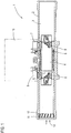
- Fig. 1 shows an ultrasonic meter 1 according to the invention, comprising a tubular housing 2 with a flow section 3, into which a measuring insert 5 defining a measuring section 4 is inserted.
- a measuring insert 5 On the outside of the tubular housing 2, two ultrasonic transducers 6, 7 are provided, via which ultrasonic signals are coupled in and out in a known manner.
- Two reflectors 8, 9 are provided on the measuring insert 5, which reflect the coupled-in ultrasonic signals axially parallel to the longitudinal axis of the measurement path, or the ultrasonic signals to be coupled out again in the direction of the adjacent ultrasonic transducer.
- the measuring insert 5 can for example be a plastic component.
- an insert 12 is arranged, which is used to influence the flow that enters the housing 2 in the direction of the arrow.
- the insert is therefore connected upstream of the measuring section 4 and influences the flow in such a way that an optimal recording of the measured values is possible.
- the insert is configured in such a way that - unlike previously in the prior art - it enables a targeted swirling of the incoming flow, and therefore targeted turbulence.
- the entire flow cross-section is separated into a large number of individual small flow cross-sections via the insert 12. This is done by means of appropriately inclined webs, which will be discussed below with reference to the individual exemplary embodiments.
- a large number of individual openings are made on the insert 12, which, viewed axially, are structured in such a way that the individual partial flows separated by this are deflected, i.e. the individual partial flows are deflected at an angle relative to the longitudinal axis of the housing. The deflection can take place uniformly in the same direction, i.e.
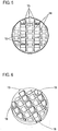
- the Figs. 2-4 show a first embodiment of an insert according to the invention, which is preferably manufactured as a plastic injection-molded part.
- This consists of an outer ring 13, which, based on the illustration in FIG Fig. 2 , run in the vertical direction, as well as second webs 15, which according to Fig. 2 run in the horizontal direction, is separated into a plurality of individual openings 16.
- Each opening defines a single, small flow cross section, so a single partial flow volume of the total flow passes through each opening.
- first and second webs 14, 15 run at right angles to one another, so that a lattice structure is formed.
- the first, vertical webs 14 define, as it were, columns lying next to one another, which are subdivided via the second webs 15 into individual openings 16 lying one above the other.
- the second webs 15 now run overall, that is to say over their entire axial length, obliquely to the longitudinal axis of the flow section 3, that is to say of the housing 2, as shown in the Figures 3 and 4 can be found.
- each partial volume, that is to say each opening 16 is delimited on two sides by inclined surfaces which, in this exemplary embodiment, run in the same direction.
- Each individual second web 15 defines, as it were, two deflecting surfaces, provided that the web is arranged in the central region of a "column", like the individual sectional views according to FIG Figures 3 and 4 demonstrate.
- the cross-section of the respective opening remains the same viewed in the axial direction, ie there are no constrictions or widening of the cross-section or the cross-sectional area that would be nozzle-shaped in any way, which has a disadvantageous effect on the flow. This applies in particular in the case of corresponding constrictions, since this increases the flow resistance.
- the cross-sections remain the same.
- the vertical webs 14 in any case run with their opening delimiting surfaces parallel to one another and axially parallel, so that they likewise do not vary the cross section.
- the webs 14 of two adjacent columns are tilted in different directions relative to the longitudinal axis, so that two adjacent columns define different deflection directions, one downwards, the other upwards. This has the effect that there is a directionally split deflection of the individual partial flows.
- FIGS. 5 and 6 show a further embodiment of an insert, the structure of the insert according to FIG Fig. 2-4 corresponds, but has its own separate fastening means, the same reference numerals being used for the same components. While the use according to the Fig. 2-4 is received in a corresponding groove 17 in the housing 2 and is fixed there by means of an additional fastening ring, for example, or snaps into an annular groove on the housing by means of a circumferential annular bead (not shown in more detail) Figures 5 and 6 Latching elements 18 on the edge are provided which latch on corresponding latching sections in the area of the housing 2.
- the latching elements 18 are, since it is a plastic component, slightly resilient, so they can be bent in and out a little so that simple latching can take place when the insert is pushed in.
- an anti-rotation lock 19 is also provided, which engages in a corresponding receptacle or recess on the housing 2 and secures the insert against rotation.
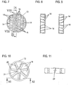
- FIGS Figures 7-9 Another embodiment of a comparable insert is shown in FIGS Figures 7-9 , the same reference numerals being used again for the same components.
- the in Fig. 7 The insert 12 shown also has an outer ring 13.
- the cross-sectional area of the outer ring 13 is divided into a large number of individual openings 16 via first webs 14, which run vertically (in the figure), and second webs 15, which run horizontally.
- first webs 14, which run vertically (in the figure) and second webs 15, which run horizontally.
- second webs are tilted differently relative to the longitudinal axis, like the Figures 8 and 9 demonstrate. So are, see Fig. 8 , the three upper second webs 14 are arranged with their left end upwards, while the three lower second webs 14 are tilted with their left end downwards. Exactly the other way around is the web tilt in the adjacent column, like Fig. 9 clearly shows.
- the individual webs are tilted overall, i.e. every second web 14 does not vary its strength or thickness, which applies to all exemplary embodiments according to the invention.
- the cross-sectional areas of the individual openings 16 delimited hereby are again the same, apart from the respective central opening where two webs converge, i.e. they do not change, so that there are no cross-sectional constrictions and the like, apart from the central opening.
- a directionally different deflection is generated within a column, the deflection directions of adjacent columns in turn being different from one another.
- considerable turbulence can also be achieved with this.
- the cross-sectional area of all complete openings which is not necessarily reduced due to their position (the openings to the edge, because it is a round component, are of course somewhat smaller than the adjacent ones to the center Openings) are all the same in cross-section.
- FIGS. 10 and 11 show an embodiment of an insert 12 not according to the invention, also consisting of an outer ring 13, the cross section of which, however, is subdivided over several, in the example shown six webs 20, which extend in a star shape from the central center 21 outward to the outer ring 13. So there are six pie-shaped openings 16, all of which are of the same size.
- Each web 20 as a whole is again at an angle to the longitudinal direction of the housing 2, each web 20 in turn delimits two adjacent openings. Since all the webs 20, which here too do not change their strength or thickness, are tilted in the same direction, the cross-sectional area of each opening 16 does not change in the direction of passage, as a result of which there are no constrictions.
- the Figures 12 and 13 show two measured value diagrams that show the flow rate in l / h along the abscissa and the measurement deviation in percent along the ordinate.
- the measured medium was water with a temperature of 20 +/- 5 ° Celsius.
- the pipe cross-section of the connection piping was DN25 / 32.
- Fig. 12 shows the measured values without use while Fig. 13 shows the measured values with use.
- An insert was used like the one in Fig. 2 is shown, that is, an application in which the direction of deflection of the openings in a column is the same, but the directions of deflection of two adjacent columns are different.
- Fig. 12 shows the result is a measured value profile or an interpolated curve which first falls and then passes through a minimum in order to then increase again to higher flow rates.
- the measured value or curve minimum is in the range of approx. 100 - 200 l / h, i.e. the range in which the laminar flow changes into turbulent flow.
- a characteristic curve correction is difficult, like the associated one Fig. 14 shows.
- Fig. 14 shows the flow rate in l / h along the abscissa and the measured value deviation in percent along the ordinate.
- Fig. 13 shows the measured values obtained, which clearly shows a steady course, i.e. the measured values show a considerable measured value deviation at lower flow rates, which, however, becomes smaller and smaller as the flow rate increases, until the measured value deviates from approx. a flow rate of 150 l / h levels off at a constant level.
- the conditions are constant, ie, a reasonable mathematical correction of the characteristic curve can be achieved, like the corresponding one Fig. 15 shows.
- Fig. 15 shows the course of the measurement deviation over the flow rate after the characteristic curve has been corrected. Obviously, all measuring points are around the 0% measurement deviation, very different from in Fig. 14 after correcting the measured values without a measuring insert.
- FIGS. 12 and 13 14 and 15, respectively, show very clearly the particular advantages of integrating the "swirl insert" according to the invention, which thus generates targeted and strongest possible turbulence in the area of the flow inlet shortly before the measuring section.
Landscapes
- Physics & Mathematics (AREA)
- Fluid Mechanics (AREA)
- General Physics & Mathematics (AREA)
- Electromagnetism (AREA)
- Measuring Volume Flow (AREA)
Claims (12)
- Compteur à ultrasons, comprenant un boîtier (2), pourvu d'une portion d'écoulement tubulaire (3) dans laquelle est inséré un insert de mesure (5) définissant une section de mesure (4), ainsi que deux transducteurs à ultrasons (6, 7) qui sont disposés côté boîtier et auxquels sont associés des réflecteurs (8, 9) disposés au niveau de l'insert de mesure (5),
un insert (12) étant placé dans la portion d'écoulement (3), lequel insert est monté en amont de l'insert de mesure (5), influe sur l'écoulement et comprend une bague extérieure (13), en appui sur la circonférence intérieure de la portion d'écoulement (3), et une pluralité de nervures (14,15) divisant la section transversale de la bague en une pluralité de passages (16) fermées latéralement,
au moins une partie des nervures (15) n'étant pas parallèle à l'axe longitudinal de la portion d'écoulement (3) pour une épaisseur de nervure constante,
les passages (16) ayant une section transversale rectangulaire et
l'insert (12) comportant une pluralité de premières nervures (14) qui s'étendent parallèlement les unes aux autres et parallèlement à l'axe longitudinal de la portion d'écoulement (3) et entre lesquelles des deuxièmes nervures (15), qui sont perpendiculaires aux premières nervures (14) et dont au moins une partie ne sont pas parallèles à l'axe longitudinal de la portion d'écoulement (3), s'étendent pour former les passages fermés (16). - Compteur à ultrasons selon la revendication 1, caractérisé en ce qu'au moins une nervure (15) de chaque passage (16) n'est pas parallèle à l'axe longitudinal de la portion d'écoulement (3).
- Compteur à ultrasons selon la revendication 1 ou 2, caractérisé en ce que les passages (16) ont une section transversale carrée.
- Compteur à ultrasons selon la revendication 1, caractérisé en ce que toutes les deuxièmes nervures (15) ne sont pas parallèles à l'axe longitudinal de la portion d'écoulement (3).
- Compteur à ultrasons selon la revendication 1 ou 4, caractérisé en ce qu'au moins une partie, de préférence la totalité, des deuxièmes nervures (15) présentes dans la zone située entre deux premières nervures (14) et non parallèles à l'axe longitudinal, s'étendent de manière identique par rapport à l'axe longitudinal.
- Compteur à ultrasons selon la revendication 1 ou 4, caractérisé en ce qu'au moins une partie des deuxièmes nervures (15) présentes dans la zone située entre deux premières nervures (14) et non parallèles à l'axe longitudinal sont inclinées dans des directions différentes, de préférence opposées, par rapport à l'axe longitudinal.
- Compteur à ultrasons selon la revendication 6, caractérisé en ce qu'un premier groupe de deuxièmes nervures (15), qui sont disposées de manière adjacente les unes aux autres, sont inclinées dans une première direction, tandis qu'un deuxième groupe de deuxièmes nervures (15), qui sont disposées de manière adjacente les unes aux autres, sont inclinées dans une direction opposée.
- Compteur à ultrasons selon l'une des revendications 5 à 7, caractérisé en ce que les deuxièmes nervures (15) de deux zones adjacentes sont inclinées dans des directions différentes par rapport à l'axe longitudinal.
- Compteur à ultrasons selon l'une des revendications précédentes, caractérisé en ce qu'une rainure radiale (17), dans laquelle l'insert (12) est maintenu, est ménagée dans la portion d'écoulement (3).
- Compteur à ultrasons selon l'une des revendications précédentes, caractérisé en ce qu'un ou plusieurs éléments d'encliquetage (18) sont prévus au niveau de l'insert, lesquels s'encliquètent au niveau de logements d'encliquetage prévus dans la portion d'écoulement (3), éventuellement de la rainure radiale.
- Compteur à ultrasons selon l'une des revendications précédentes, caractérisé en ce qu'un blocage en rotation (19), notamment une saillie radiale, qui s'engage dans un logement radial ménagé dans la portion d'écoulement (3), en particulier de la rainure radiale, est prévu au niveau de l'insert (12).
- Compteur à ultrasons selon l'une des revendications précédentes, caractérisé en ce que l'insert (12) est une pièce en matière synthétique moulée par injection.
Applications Claiming Priority (1)
| Application Number | Priority Date | Filing Date | Title |
|---|---|---|---|
| DE102011112028.2A DE102011112028B4 (de) | 2011-08-31 | 2011-08-31 | Ultraschallzähler |
Publications (2)
| Publication Number | Publication Date |
|---|---|
| EP2565593A1 EP2565593A1 (fr) | 2013-03-06 |
| EP2565593B1 true EP2565593B1 (fr) | 2020-10-07 |
Family
ID=46762797
Family Applications (1)
| Application Number | Title | Priority Date | Filing Date |
|---|---|---|---|
| EP12005751.8A Active EP2565593B1 (fr) | 2011-08-31 | 2012-08-08 | Compteur à ultrasons |
Country Status (3)
| Country | Link |
|---|---|
| EP (1) | EP2565593B1 (fr) |
| CN (1) | CN202869565U (fr) |
| DE (1) | DE102011112028B4 (fr) |
Families Citing this family (16)
| Publication number | Priority date | Publication date | Assignee | Title |
|---|---|---|---|---|
| WO2016012024A1 (fr) * | 2014-07-21 | 2016-01-28 | Apator Miitors Aps | Accessoire intérieur de conduit pour un débitmètre ultrasonore |
| CN105987730A (zh) * | 2015-01-30 | 2016-10-05 | 浙江超仪电子技术股份有限公司 | 一种超声波流量传感器及超声波流量计 |
| GB2542354B8 (en) * | 2015-09-15 | 2022-05-11 | Ft Tech Uk Ltd | Wind sensor housing |
| CN105784031B (zh) * | 2016-02-29 | 2019-10-15 | 浙江天信超声技术有限公司 | 一种气体整流装置 |
| US10444051B2 (en) * | 2017-01-09 | 2019-10-15 | Georg Fischer Signet, LLC | Ultrasonic sensor assembly and method of manufacture |
| JP6747994B2 (ja) * | 2017-01-26 | 2020-08-26 | 株式会社キーエンス | 超音波流量センサ及びその取付方法 |
| DE102017002378B4 (de) | 2017-03-11 | 2022-02-17 | Diehl Metering Gmbh | Fluidzähler |
| DE102017010282B4 (de) | 2017-09-09 | 2022-04-21 | Diehl Metering Gmbh | Durchflusszähler und Verfahren zur Herstellung eines Durchflusszählers |
| DK3454018T3 (da) * | 2017-09-09 | 2022-09-05 | Diehl Metering Gmbh | Gennemstrømningsmåler og fremgangsmåde til fremstilling af en gennemstrømningsmåler |
| CN108318090B (zh) * | 2018-01-22 | 2023-11-07 | 重庆市生态环境科学研究院 | 适用于大口径管道流量测量的流量计 |
| EP3537112A1 (fr) * | 2018-03-08 | 2019-09-11 | Energoflow AG | Débitmètre d'écoulement fluide |
| EP3757527B1 (fr) * | 2019-06-25 | 2021-06-09 | SICK Engineering GmbH | Débitmètre à ultra sons |
| US12123759B2 (en) * | 2019-11-19 | 2024-10-22 | Panasonic Intellectual Property Management Co., Ltd. | Ultrasonic flowmeter |
| EP4273511A1 (fr) * | 2022-05-04 | 2023-11-08 | Sartorius Stedim Biotech GmbH | Appareil d'agencement sur une conduite guidant un liquide et d'application d'un dispositif à écoulement continu et procédé de détection d'une grandeur à mesurer d'un fluide acheminé dans une conduite |
| CN116202026B (zh) * | 2023-02-27 | 2025-10-14 | 深圳市安保医疗科技股份有限公司 | 一种制氧机用通气组件 |
| CN118190090B (zh) * | 2024-02-01 | 2025-02-11 | 安徽欧泰祺智慧水务科技有限公司 | 整流结构及超声波测量装置 |
Family Cites Families (9)
| Publication number | Priority date | Publication date | Assignee | Title |
|---|---|---|---|---|
| US4365518A (en) * | 1981-02-23 | 1982-12-28 | Mapco, Inc. | Flow straighteners in axial flowmeters |
| US4929088A (en) * | 1988-07-27 | 1990-05-29 | Vortab Corporation | Static fluid flow mixing apparatus |
| GB9215043D0 (en) * | 1992-07-15 | 1992-08-26 | Flow Inc K | Fluid mass flow meters |
| EP0831303B1 (fr) * | 1996-08-21 | 2008-04-23 | Endress + Hauser Flowtec AG | Capteur de débit à tourbillon avec une grille à turbulence |
| DE19647081A1 (de) * | 1996-11-14 | 1998-05-28 | Bosch Gmbh Robert | Vorrichtung zur Messung der Masse eines strömenden Mediums |
| DE102004060065B4 (de) * | 2004-12-14 | 2016-10-20 | Robert Bosch Gmbh | Ultraschall Durchflussmesser mit Leitelementen |
| DK1775560T3 (da) * | 2005-10-14 | 2011-01-31 | Kamstrup As | Ultralydsstrømningsmåler med strømningsblander |
| DE102006030942A1 (de) * | 2006-07-05 | 2008-01-10 | Landis+Gyr Gmbh | Durchflussmesser mit einem Einlaufbereich und einer Durchflussmessstrecke |
| DE102008049891B4 (de) * | 2008-10-02 | 2012-12-06 | Hydrometer Gmbh | Strömungsrichter für ein Durchflussmessgerät, insbesondere ein Ultraschallmessgerät |
-
2011
- 2011-08-31 DE DE102011112028.2A patent/DE102011112028B4/de not_active Expired - Fee Related
-
2012
- 2012-08-08 EP EP12005751.8A patent/EP2565593B1/fr active Active
- 2012-08-15 CN CN2012204034094U patent/CN202869565U/zh not_active Expired - Lifetime
Non-Patent Citations (1)
| Title |
|---|
| None * |
Also Published As
| Publication number | Publication date |
|---|---|
| DE102011112028A1 (de) | 2013-02-28 |
| CN202869565U (zh) | 2013-04-10 |
| DE102011112028B4 (de) | 2021-07-01 |
| EP2565593A1 (fr) | 2013-03-06 |
Similar Documents
| Publication | Publication Date | Title |
|---|---|---|
| DE102011112028B4 (de) | Ultraschallzähler | |
| EP2172657B1 (fr) | Guide d'écoulement pour un appareil de mesure du débit, notamment un appareil de mesure à ultrasons | |
| EP1613928B1 (fr) | Ensemble compteur a gaz a geometrie d'ecoulement amelioree | |
| EP3004812B1 (fr) | Débitmètre ultrasonique | |
| EP3599446B1 (fr) | Compteur à ultrasons | |
| EP2625492B1 (fr) | Débitmètre massique à effet coriolis | |
| EP2607718B1 (fr) | Tranquilliseur de débit | |
| DE102013009347A1 (de) | Durchflussmesser | |
| DE102007023119A1 (de) | Strömungsführungselement zur Führung einer Strömung eines fluiden Mediums | |
| EP3314214B1 (fr) | Débitmètre comprenant un canal de mesure et des canaux auxiliaires | |
| EP3277998B1 (fr) | Conditionneur d'écoulement | |
| EP3267158A1 (fr) | Compteur à ultrasons destiné à enregistrer le débit d'un fluide | |
| EP3321645B1 (fr) | Compteur d'écoulement à ultrasons | |
| DE102010062892A1 (de) | Strömungsgitter zum Einsatz in einem Strömungsrohr eines strömenden fluiden Mediums | |
| DE102019103674A1 (de) | Durchflussmessanordnung und strömungstechnische Anordnung | |
| EP3306277A1 (fr) | Débitmètre à effet coriolis et son procédé de fonctionnement | |
| EP4089357A1 (fr) | Echangeur de chaleur | |
| DE102008042807B4 (de) | Vorrichtung zur Bestimmung eines Parameters eines strömenden fluiden Mediums | |
| EP3748309B1 (fr) | Débitmètre à ultrasons, utilisation d'un débitmètre à ultrasons dans un organe d'arrêt et organe d'arrêt | |
| DE102015003365A1 (de) | Coriolis-Massendurchflussmessgerät | |
| WO2014127964A1 (fr) | Élément de transfert thermique | |
| DE102006047526A1 (de) | Strömungsgleichrichter | |
| EP2986953B1 (fr) | Débitmètre | |
| EP3669133B1 (fr) | Échangeur de chaleur | |
| DE10109161B4 (de) | Durchflußmesser |
Legal Events
| Date | Code | Title | Description |
|---|---|---|---|
| PUAI | Public reference made under article 153(3) epc to a published international application that has entered the european phase |
Free format text: ORIGINAL CODE: 0009012 |
|
| AK | Designated contracting states |
Kind code of ref document: A1 Designated state(s): AL AT BE BG CH CY CZ DE DK EE ES FI FR GB GR HR HU IE IS IT LI LT LU LV MC MK MT NL NO PL PT RO RS SE SI SK SM TR |
|
| AX | Request for extension of the european patent |
Extension state: BA ME |
|
| 17P | Request for examination filed |
Effective date: 20130828 |
|
| RBV | Designated contracting states (corrected) |
Designated state(s): AL AT BE BG CH CY CZ DE DK EE ES FI FR GB GR HR HU IE IS IT LI LT LU LV MC MK MT NL NO PL PT RO RS SE SI SK SM TR |
|
| RAP1 | Party data changed (applicant data changed or rights of an application transferred) |
Owner name: DIEHL METERING GMBH |
|
| STAA | Information on the status of an ep patent application or granted ep patent |
Free format text: STATUS: EXAMINATION IS IN PROGRESS |
|
| 17Q | First examination report despatched |
Effective date: 20190426 |
|
| GRAP | Despatch of communication of intention to grant a patent |
Free format text: ORIGINAL CODE: EPIDOSNIGR1 |
|
| STAA | Information on the status of an ep patent application or granted ep patent |
Free format text: STATUS: GRANT OF PATENT IS INTENDED |
|
| INTG | Intention to grant announced |
Effective date: 20200625 |
|
| GRAS | Grant fee paid |
Free format text: ORIGINAL CODE: EPIDOSNIGR3 |
|
| GRAA | (expected) grant |
Free format text: ORIGINAL CODE: 0009210 |
|
| STAA | Information on the status of an ep patent application or granted ep patent |
Free format text: STATUS: THE PATENT HAS BEEN GRANTED |
|
| AK | Designated contracting states |
Kind code of ref document: B1 Designated state(s): AL AT BE BG CH CY CZ DE DK EE ES FI FR GB GR HR HU IE IS IT LI LT LU LV MC MK MT NL NO PL PT RO RS SE SI SK SM TR |
|
| REG | Reference to a national code |
Ref country code: GB Ref legal event code: FG4D Free format text: NOT ENGLISH |
|
| REG | Reference to a national code |
Ref country code: CH Ref legal event code: EP Ref country code: AT Ref legal event code: REF Ref document number: 1321646 Country of ref document: AT Kind code of ref document: T Effective date: 20201015 |
|
| REG | Reference to a national code |
Ref country code: IE Ref legal event code: FG4D Free format text: LANGUAGE OF EP DOCUMENT: GERMAN |
|
| REG | Reference to a national code |
Ref country code: DE Ref legal event code: R096 Ref document number: 502012016393 Country of ref document: DE |
|
| REG | Reference to a national code |
Ref country code: NL Ref legal event code: MP Effective date: 20201007 |
|
| PG25 | Lapsed in a contracting state [announced via postgrant information from national office to epo] |
Ref country code: NO Free format text: LAPSE BECAUSE OF FAILURE TO SUBMIT A TRANSLATION OF THE DESCRIPTION OR TO PAY THE FEE WITHIN THE PRESCRIBED TIME-LIMIT Effective date: 20210107 Ref country code: NL Free format text: LAPSE BECAUSE OF FAILURE TO SUBMIT A TRANSLATION OF THE DESCRIPTION OR TO PAY THE FEE WITHIN THE PRESCRIBED TIME-LIMIT Effective date: 20201007 Ref country code: PT Free format text: LAPSE BECAUSE OF FAILURE TO SUBMIT A TRANSLATION OF THE DESCRIPTION OR TO PAY THE FEE WITHIN THE PRESCRIBED TIME-LIMIT Effective date: 20210208 Ref country code: FI Free format text: LAPSE BECAUSE OF FAILURE TO SUBMIT A TRANSLATION OF THE DESCRIPTION OR TO PAY THE FEE WITHIN THE PRESCRIBED TIME-LIMIT Effective date: 20201007 Ref country code: RS Free format text: LAPSE BECAUSE OF FAILURE TO SUBMIT A TRANSLATION OF THE DESCRIPTION OR TO PAY THE FEE WITHIN THE PRESCRIBED TIME-LIMIT Effective date: 20201007 Ref country code: GR Free format text: LAPSE BECAUSE OF FAILURE TO SUBMIT A TRANSLATION OF THE DESCRIPTION OR TO PAY THE FEE WITHIN THE PRESCRIBED TIME-LIMIT Effective date: 20210108 |
|
| REG | Reference to a national code |
Ref country code: LT Ref legal event code: MG4D |
|
| PG25 | Lapsed in a contracting state [announced via postgrant information from national office to epo] |
Ref country code: BG Free format text: LAPSE BECAUSE OF FAILURE TO SUBMIT A TRANSLATION OF THE DESCRIPTION OR TO PAY THE FEE WITHIN THE PRESCRIBED TIME-LIMIT Effective date: 20210107 Ref country code: IS Free format text: LAPSE BECAUSE OF FAILURE TO SUBMIT A TRANSLATION OF THE DESCRIPTION OR TO PAY THE FEE WITHIN THE PRESCRIBED TIME-LIMIT Effective date: 20210207 Ref country code: ES Free format text: LAPSE BECAUSE OF FAILURE TO SUBMIT A TRANSLATION OF THE DESCRIPTION OR TO PAY THE FEE WITHIN THE PRESCRIBED TIME-LIMIT Effective date: 20201007 Ref country code: LV Free format text: LAPSE BECAUSE OF FAILURE TO SUBMIT A TRANSLATION OF THE DESCRIPTION OR TO PAY THE FEE WITHIN THE PRESCRIBED TIME-LIMIT Effective date: 20201007 Ref country code: PL Free format text: LAPSE BECAUSE OF FAILURE TO SUBMIT A TRANSLATION OF THE DESCRIPTION OR TO PAY THE FEE WITHIN THE PRESCRIBED TIME-LIMIT Effective date: 20201007 Ref country code: SE Free format text: LAPSE BECAUSE OF FAILURE TO SUBMIT A TRANSLATION OF THE DESCRIPTION OR TO PAY THE FEE WITHIN THE PRESCRIBED TIME-LIMIT Effective date: 20201007 |
|
| PG25 | Lapsed in a contracting state [announced via postgrant information from national office to epo] |
Ref country code: HR Free format text: LAPSE BECAUSE OF FAILURE TO SUBMIT A TRANSLATION OF THE DESCRIPTION OR TO PAY THE FEE WITHIN THE PRESCRIBED TIME-LIMIT Effective date: 20201007 |
|
| REG | Reference to a national code |
Ref country code: DE Ref legal event code: R097 Ref document number: 502012016393 Country of ref document: DE |
|
| PG25 | Lapsed in a contracting state [announced via postgrant information from national office to epo] |
Ref country code: EE Free format text: LAPSE BECAUSE OF FAILURE TO SUBMIT A TRANSLATION OF THE DESCRIPTION OR TO PAY THE FEE WITHIN THE PRESCRIBED TIME-LIMIT Effective date: 20201007 Ref country code: CZ Free format text: LAPSE BECAUSE OF FAILURE TO SUBMIT A TRANSLATION OF THE DESCRIPTION OR TO PAY THE FEE WITHIN THE PRESCRIBED TIME-LIMIT Effective date: 20201007 Ref country code: SM Free format text: LAPSE BECAUSE OF FAILURE TO SUBMIT A TRANSLATION OF THE DESCRIPTION OR TO PAY THE FEE WITHIN THE PRESCRIBED TIME-LIMIT Effective date: 20201007 Ref country code: LT Free format text: LAPSE BECAUSE OF FAILURE TO SUBMIT A TRANSLATION OF THE DESCRIPTION OR TO PAY THE FEE WITHIN THE PRESCRIBED TIME-LIMIT Effective date: 20201007 Ref country code: SK Free format text: LAPSE BECAUSE OF FAILURE TO SUBMIT A TRANSLATION OF THE DESCRIPTION OR TO PAY THE FEE WITHIN THE PRESCRIBED TIME-LIMIT Effective date: 20201007 Ref country code: RO Free format text: LAPSE BECAUSE OF FAILURE TO SUBMIT A TRANSLATION OF THE DESCRIPTION OR TO PAY THE FEE WITHIN THE PRESCRIBED TIME-LIMIT Effective date: 20201007 |
|
| PLBE | No opposition filed within time limit |
Free format text: ORIGINAL CODE: 0009261 |
|
| STAA | Information on the status of an ep patent application or granted ep patent |
Free format text: STATUS: NO OPPOSITION FILED WITHIN TIME LIMIT |
|
| PG25 | Lapsed in a contracting state [announced via postgrant information from national office to epo] |
Ref country code: DK Free format text: LAPSE BECAUSE OF FAILURE TO SUBMIT A TRANSLATION OF THE DESCRIPTION OR TO PAY THE FEE WITHIN THE PRESCRIBED TIME-LIMIT Effective date: 20201007 |
|
| 26N | No opposition filed |
Effective date: 20210708 |
|
| PG25 | Lapsed in a contracting state [announced via postgrant information from national office to epo] |
Ref country code: IT Free format text: LAPSE BECAUSE OF FAILURE TO SUBMIT A TRANSLATION OF THE DESCRIPTION OR TO PAY THE FEE WITHIN THE PRESCRIBED TIME-LIMIT Effective date: 20201007 Ref country code: AL Free format text: LAPSE BECAUSE OF FAILURE TO SUBMIT A TRANSLATION OF THE DESCRIPTION OR TO PAY THE FEE WITHIN THE PRESCRIBED TIME-LIMIT Effective date: 20201007 |
|
| PG25 | Lapsed in a contracting state [announced via postgrant information from national office to epo] |
Ref country code: SI Free format text: LAPSE BECAUSE OF FAILURE TO SUBMIT A TRANSLATION OF THE DESCRIPTION OR TO PAY THE FEE WITHIN THE PRESCRIBED TIME-LIMIT Effective date: 20201007 |
|
| REG | Reference to a national code |
Ref country code: CH Ref legal event code: PL |
|
| PG25 | Lapsed in a contracting state [announced via postgrant information from national office to epo] |
Ref country code: MC Free format text: LAPSE BECAUSE OF FAILURE TO SUBMIT A TRANSLATION OF THE DESCRIPTION OR TO PAY THE FEE WITHIN THE PRESCRIBED TIME-LIMIT Effective date: 20201007 |
|
| REG | Reference to a national code |
Ref country code: BE Ref legal event code: MM Effective date: 20210831 |
|
| PG25 | Lapsed in a contracting state [announced via postgrant information from national office to epo] |
Ref country code: LI Free format text: LAPSE BECAUSE OF NON-PAYMENT OF DUE FEES Effective date: 20210831 Ref country code: CH Free format text: LAPSE BECAUSE OF NON-PAYMENT OF DUE FEES Effective date: 20210831 |
|
| PG25 | Lapsed in a contracting state [announced via postgrant information from national office to epo] |
Ref country code: IS Free format text: LAPSE BECAUSE OF FAILURE TO SUBMIT A TRANSLATION OF THE DESCRIPTION OR TO PAY THE FEE WITHIN THE PRESCRIBED TIME-LIMIT Effective date: 20210207 Ref country code: LU Free format text: LAPSE BECAUSE OF NON-PAYMENT OF DUE FEES Effective date: 20210808 |
|
| PG25 | Lapsed in a contracting state [announced via postgrant information from national office to epo] |
Ref country code: IE Free format text: LAPSE BECAUSE OF NON-PAYMENT OF DUE FEES Effective date: 20210808 Ref country code: BE Free format text: LAPSE BECAUSE OF NON-PAYMENT OF DUE FEES Effective date: 20210831 |
|
| REG | Reference to a national code |
Ref country code: AT Ref legal event code: MM01 Ref document number: 1321646 Country of ref document: AT Kind code of ref document: T Effective date: 20210808 |
|
| PG25 | Lapsed in a contracting state [announced via postgrant information from national office to epo] |
Ref country code: AT Free format text: LAPSE BECAUSE OF NON-PAYMENT OF DUE FEES Effective date: 20210808 |
|
| PG25 | Lapsed in a contracting state [announced via postgrant information from national office to epo] |
Ref country code: HU Free format text: LAPSE BECAUSE OF FAILURE TO SUBMIT A TRANSLATION OF THE DESCRIPTION OR TO PAY THE FEE WITHIN THE PRESCRIBED TIME-LIMIT; INVALID AB INITIO Effective date: 20120808 Ref country code: CY Free format text: LAPSE BECAUSE OF FAILURE TO SUBMIT A TRANSLATION OF THE DESCRIPTION OR TO PAY THE FEE WITHIN THE PRESCRIBED TIME-LIMIT Effective date: 20201007 |
|
| PG25 | Lapsed in a contracting state [announced via postgrant information from national office to epo] |
Ref country code: MK Free format text: LAPSE BECAUSE OF FAILURE TO SUBMIT A TRANSLATION OF THE DESCRIPTION OR TO PAY THE FEE WITHIN THE PRESCRIBED TIME-LIMIT Effective date: 20201007 |
|
| PG25 | Lapsed in a contracting state [announced via postgrant information from national office to epo] |
Ref country code: TR Free format text: LAPSE BECAUSE OF FAILURE TO SUBMIT A TRANSLATION OF THE DESCRIPTION OR TO PAY THE FEE WITHIN THE PRESCRIBED TIME-LIMIT Effective date: 20201007 |
|
| PG25 | Lapsed in a contracting state [announced via postgrant information from national office to epo] |
Ref country code: MT Free format text: LAPSE BECAUSE OF FAILURE TO SUBMIT A TRANSLATION OF THE DESCRIPTION OR TO PAY THE FEE WITHIN THE PRESCRIBED TIME-LIMIT Effective date: 20201007 |
|
| PGFP | Annual fee paid to national office [announced via postgrant information from national office to epo] |
Ref country code: GB Payment date: 20250821 Year of fee payment: 14 |
|
| PGFP | Annual fee paid to national office [announced via postgrant information from national office to epo] |
Ref country code: FR Payment date: 20250829 Year of fee payment: 14 |
|
| PGFP | Annual fee paid to national office [announced via postgrant information from national office to epo] |
Ref country code: DE Payment date: 20251020 Year of fee payment: 14 |