EP2565614A2 - Rotationsmikrotom - Google Patents
Rotationsmikrotom Download PDFInfo
- Publication number
- EP2565614A2 EP2565614A2 EP12179496A EP12179496A EP2565614A2 EP 2565614 A2 EP2565614 A2 EP 2565614A2 EP 12179496 A EP12179496 A EP 12179496A EP 12179496 A EP12179496 A EP 12179496A EP 2565614 A2 EP2565614 A2 EP 2565614A2
- Authority
- EP
- European Patent Office
- Prior art keywords
- drive
- crank
- rotary microtome
- actuator
- housing
- Prior art date
- Legal status (The legal status is an assumption and is not a legal conclusion. Google has not performed a legal analysis and makes no representation as to the accuracy of the status listed.)
- Granted
Links
Images

Classifications
-
- G—PHYSICS
- G01—MEASURING; TESTING
- G01N—INVESTIGATING OR ANALYSING MATERIALS BY DETERMINING THEIR CHEMICAL OR PHYSICAL PROPERTIES
- G01N1/00—Sampling; Preparing specimens for investigation
- G01N1/02—Devices for withdrawing samples
- G01N1/04—Devices for withdrawing samples in the solid state, e.g. by cutting
- G01N1/06—Devices for withdrawing samples in the solid state, e.g. by cutting providing a thin slice, e.g. microtome
Definitions
- the invention relates to a rotary microtome with a micrometer, a micrometer associated with the object holding device, a drive for the micrometer for preferably moving the vertical object holding device, a frame for holding the micrometer and possibly the drive, a housing and a relation to the object holding device outside the housing a knife-carrying knife holding device, wherein a rotatable actuating member is provided for manual drive.
- Microtomes of various designs are well known from the printed prior art. Just as an example since on the DE 43 39 071 A1 and on the DE 102 44 687 A1 directed.
- Known rotary microtome is provided laterally on the housing a handwheel with eccentrically arranged on the handwheel crank as an actuator, which can be the micrometer - manually - drive. If you were to equip the known rotary microtome with an electric drive, so the actuator, ie the handwheel and especially the crank, forcibly rotate. However, this is problematic in practice, since there is a risk of injury due to the rotating movement of the eccentrically arranged crank.
- crank in a central position of the handwheel, d. H. into the axis of rotation, to relocate so that an eccentric movement of the crank brings no risk of injury.
- Other known from practice alternatives are retractable or retractable cranks so that they do not hinder the user or at most insignificant.
- the present invention is therefore based on the object, a rotary microtome, which is suitable both for manual operation and for electrical / electronic Operation is suitable to design and further develop that with the simplest construction, the actuator does not interfere, at least no risk of injury in itself.
- the generic rotary microtome is designed in a surprisingly simple manner that a blocking device is provided which blocks the rotational movement of the actuator via a sliding element.
- the eccentrically arranged on the hand crank when the actual standstill of the handwheel, for example, when the user performs an activity on the object holder, or in electrical operation of the rotary microtome, then at least not or no longer bothers when on the Crank or the handwheel a very special blocking acts, which completely blocks the rotational movement of the actuator, at least the eccentric circular motion of the crank.
- the handwheel and there eccentrically arranged crank is fixed, so that a hindrance or even risk of injury from the crank can not go out.
- a sliding element is provided for this purpose, which is preferably arranged so as to be displaceable horizontally in or close to the housing wall and causes the blocking via a particular mechanism via the displacement movement.
- the actuating member advantageously comprises a handwheel rotatable for manual drive, which in a further advantageous manner comprises a crank arranged eccentrically there.
- the crank is rotatable about its own axis on the hand wheel, so that when holding the crank, the hand wheel is rotatable, namely in the manual mode of rotation microtome. If the microtome - for example, when working on the object holder - are not manually operated or driven, for example, electrically / electronically or automatically, the handwheel can be detected with the there eccentrically arranged crank, namely on the inventively provided blocking device. An obstruction by the crank or the risk of injury due to the otherwise running on a circular path movement of the crank is thus excluded.
- the blocking device is automatically activated, namely, when the drive is switched from manual to electrical and vice versa deactivated. It is thus possible, for example, to design a changeover switch from manual to electrical in such a way that it simultaneously activates the blocking device, namely when switching over to an electrical operation. If, however, switched back again from electrical operation to a manual operation, the blocking device can be automatically deactivated and thus the rotational movement of the actuator to be released. An electrical actuation of the blocking device is conceivable.
- At least one optional electric / electronic drive it may also be advantageous if the operation or clamping of the blocking device is monitored. In this case, a switch from a manual to an electric drive could only be possible if the activation of the blocking device - by appropriate detection - is detected. Another safety factor is created by this measure.
- the blocking device comprises a preferably horizontally displaceable sliding element. More specifically, by horizontally displacing a latch across an inclined plane, a bearing buffer can vertically displace a long shaft and a further shaft via a ball bearing. A provided on the buffer buffer gum could then press on the handwheel and block it.
- the displacement element presses an abutment on confirmation of a rotatable part of the actuator and thereby blocks the actuator with respect to the rotational movement.
- a blocking of the actuator ensured when the rotary microtome is to be operated electrically. It is essential that takes place between the micrometer and the actuator decoupling.
- the abutment comprises a rubber buffer o. ⁇ ., So that takes place due to friction blocking of the actuator.
- the actuator in particular the crank eccentrically arranged on the handwheel
- the mere provision of the crank could in any case disturb it when used not needed to operate or drive the micrometer.
- the crank is removable by actuation of a release mechanism.
- this may also be an alternative measure for the provision of the blocking device insofar as after releasing the crank, it is not absolutely necessary to prevent the rotational movement of the actuator, namely in the absence of projecting from the housing, eccentrically rotating part of the actuator.
- the release mechanism may be automatically activated, similar to the blocking device discussed above, namely when the drive is switched from manual to electrical and vice versa. It is also conceivable that the projecting from the housing, eccentrically rotating part of the actuator, namely, for example, the crank or the like. Is automatically ejected when switching from manual to electrical operation, so that a kind of forced decoupling takes place.
- the release mechanism may comprise a push button, by the actuation of which via a shaft an operative connection, for example, between the crank and the handwheel is releasable.
- a simple removal of the crank is thus possible with the simplest mechanical design.
- Fig. 1 shows an embodiment of a rotary microtome according to the invention, where there the micrometer is arranged inside a housing 1. Visible is the object holder 2, which serves to hold a sample to be cut.
- a drive for the micrometer mechanism is provided, namely for moving the object holding device 2 more or less vertically.
- a frame or a frame serves to receive the micrometer mechanism and optionally the drive, wherein the frame can be an integral part of the housing 1.
- FIG. 1 clearly the arrangement of an object holder 2 and a knife support 3 usually carrying a knife, wherein the object holder 2 or the object held there or the sample is moved past the held by the knife holder 3 knife under realization of a feed movement, so that an adjustable fine cut to Making thin samples is possible.
- the drive is optionally via a rotatable actuating member 4, which comprises a hand wheel 5 and an eccentric crank 6 in the embodiment shown here.
- this is a rotary microtome which can be driven either manually or electrically, ie via a corresponding electric motor.
- an in Fig. 1 Blocking device 8 indicated by a slide switch 7, which blocks the rotational movement of the actuating member 4 and the rotational movement of the handwheel 5 and thus the orbit movement of the crank 6, namely, when the rotary microtome is to be operated electrically. A hazardous to the operator circular path movement of the crank 6 is thus excluded.
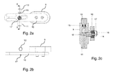
- Fig. 2a, 2b and 2c show the blocking device 8 in detail, wherein in the figures as essential components of the blocking device 8, a grip 9, a latch 10, a shaft 11, a bearing shaft 12, a bearing buffer 13, another bearing 14, a nut 15, a locking ring 16 and a screw 17 can be seen.
- the bearing buffer 13 By horizontally displacing the bolt 10, the bearing buffer 13 is displaced vertically over the bearing 14, the bearing shaft 12 and the shaft 11 via an inclined plane. The rubber coating of the bearing buffer 13 presses after this shift to the handwheel 5 and fixes this, so that further rotation of the handwheel 5 is no longer possible.
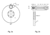
- Fig. 3a and 3b show in two views the provision of a release mechanism 18, by which a part of the actuating member 4, namely the crank 6, from the handwheel 5 is removable.
- FIG. 3a and 3b the hand wheel 5, a handle shell 19, a crank receptacle 20, a bearing shaft 21, a push button 22, a shaft 23, a retaining ring 24, a ball 25, a screw 26, a compression spring 27 and a screw 28th
- the shaft 23 By pressing the push button 22, the shaft 23 can be moved axially.
- the balls 25 can then escape due to the resulting by the displacement cavity inwards and the handle or the crank 6 can be easily pulled out of the crank holder 20, so that no disturbing component protrudes from the handwheel 5 more.
- a possible rotational movement of the handwheel 5 then no longer plays a part, in any case means no further risk of injury to the operator, not even if the handwheel rotates with electric drive, namely in the absence of a corresponding blocking device.
Landscapes
- Physics & Mathematics (AREA)
- Health & Medical Sciences (AREA)
- Life Sciences & Earth Sciences (AREA)
- Chemical & Material Sciences (AREA)
- Analytical Chemistry (AREA)
- Biochemistry (AREA)
- General Health & Medical Sciences (AREA)
- General Physics & Mathematics (AREA)
- Immunology (AREA)
- Pathology (AREA)
- Sampling And Sample Adjustment (AREA)
Abstract
Description
- Die Erfindung betrifft ein Rotationsmikrotom mit einem Mikrometerwerk, einer dem Mikrometerwerk zugeordneten Objekthalteeinrichtung, einem Antrieb für das Mikrometerwerk zum vorzugsweise vertikalen Bewegen der Objekthalteeinrichtung, einem Gestell zur Aufnahme des Mikrometerwerks und ggf. des Antriebs, einem Gehäuse und einer gegenüber der Objekthalteeinrichtung außerhalb des Gehäuses angeordneten, eine Messer tragenden Messerhalteeinrichtung, wobei zum manuellen Antrieb ein drehbares Betätigungsorgan vorgesehen ist.
- Mikrotome unterschiedlichster Bauart sind hinlänglich aus dem druckschriftlichen Stand der Technik bekannt. Lediglich beispielhaft seit dazu auf die
DE 43 39 071 A1 und auf dieDE 102 44 687 A1 verwiesen. - Bei dem aus der
DE 102 44 687 A1 bekannten Rotationsmikrotom ist seitlich am Gehäuse ein Handrad mit exzentrisch am Handrad angeordneter Kurbel als Betätigungsorgan vorgesehen, wodurch sich das Mikrometerwerk - manuell - antreiben lässt. Würde man das bekannte Rotationsmikrotom mit einem elektrischen Antrieb ausstatten, so würde das Betätigungsorgan, d. h. das Handrad und v. a. die Kurbel, zwangsweise mitdrehen. Dies ist jedoch in der Praxis problematisch, da auf Grund der rotierenden Bewegung der exzentrisch angeordneten Kurbel Verletzungsgefahr besteht. - Aus dem Stand der Technik ist bereits bekannt, die Kurbel in eine mittige Position des Handrads, d. h. in die Drehachse hinein, zu verlagern, damit eine exzentrische Bewegung der Kurbel keine Verletzungsgefahr mit sich bringt. Weitere aus der Praxis bekannte Alternativen sind einklappbare oder versenkbare Kurbeln, so dass diese den Anwender nicht oder allenfalls unwesentlich behindern.
- Die aus der Praxis bekannten Rotationsmikrotome und die dort realisierten Mechanismen zum "Entschärfen" der Kurbel sind jedoch in der Praxis unzureichend, da von ihnen immer noch eine nicht unerhebliche Behinderung und sogar Verletzungsgefahr ausgeht. Außerdem sind die dort vorgeschlagenen Lösungen konstruktiv aufwändig und daher kostenintensiv.
- Der vorliegenden Erfindung liegt daher die Aufgabe zu Grunde, ein Rotationsmikrotom, welches sich sowohl zum Handbetrieb als auch zum elektrischen/elektronischen Betrieb eignet, derart auszugestalten und weiterzubilden, dass bei einfachster Konstruktion das Betätigungsorgan nicht stört, jedenfalls keine Verletzungsgefahr in sich birgt.
- Voranstehende Aufgabe ist durch die Merkmale des Patentanspruchs 1 gelöst. Danach ist das gattungsbildende Rotationsmikrotom auf verblüffend einfache Weise dadurch ausgebildet, dass eine Blockiereinrichtung vorgesehen ist, die die Drehbewegung des Betätigungsorgans über ein Schiebeelement blockiert.
- Erfindungsgemäß ist erkannt worden, dass die am Handrad exzentrisch angeordnete Kurbel beim eigentlichen Stillstand des Handrads, beispielsweise dann, wenn der Anwender an der Objekthalteeinrichtung eine Tätigkeit ausübt, oder beim elektrischen Betrieb des Rotationsmikrotoms, dann jedenfalls nicht bzw. nicht mehr stört, wenn auf die Kurbel bzw. das Handrad eine ganz besondere Blockiereinrichtung wirkt, die die Drehbewegung des Betätigungsorgans, zumindest die exzentrische Kreisbewegung der Kurbel, vollständig blockiert. In diesem Falle steht das Handrad und die dort exzentrisch angeordnete Kurbel fest, so dass eine Behinderung oder gar Verletzungsgefahr von der Kurbel nicht mehr ausgehen kann. In ganz besonders raffinierter Weise ist dazu ein Schiebeelement vorgesehen, welches vorzugsweise horizontal in oder nahe an der Gehäusewandung verschiebbar angeordnet ist und über die Verschiebebewegung die Blockierung über einen besonderen Mechanismus hervorruft.
- Wie bereits zuvor erwähnt, umfasst das Betätigungsorgan in vorteilhafter Weise ein zum manuellen Antrieb drehbares Handrad, welches in weiter vorteilhafter Weise eine dort exzentrisch angeordnete Kurbel umfasst. Die Kurbel ist um ihre eigene Achse am Handrad drehbar, so dass beim Festhalten der Kurbel das Handrad drehbar ist, nämlich in der manuellen Betriebsart des Rotationsmikrotoms. Soll das Mikrotom - beispielsweise bei Arbeiten an der Objekthalteeinrichtung - nicht manuell betätigt werden oder beispielsweise elektrisch/elektronisch bzw. automatisch angetrieben werden, lässt sich das Handrad mit der dort exzentrisch angeordneten Kurbel feststellen, nämlich über die erfindungsgemäß vorgesehene Blockiereinrichtung. Eine Behinderung durch die Kurbel oder die Gefahr einer Verletzung auf Grund der ansonsten auf einer Kreisbahn verlaufenden Bewegung der Kurbel ist somit ausgeschlossen.
- Damit es möglich ist, das Betätigungsorgan bzw. die Kurbel in eine nicht störende Position zu verbringen, ist es von weiterem Vorteil, wenn das Betätigungsorgan in jeder beliebigen Winkelposition relativ zum Gehäuse arretierbar ist, nämlich entlang einer 360°-Drehung.
- Im Rahmen einer besonders raffinierten Ausgestaltung ist von Vorteil, wenn die Blockiereinrichtung automatisch aktivierbar ist, nämlich dann, wenn der Antrieb von manuell auf elektrisch geschaltet wird und umgekehrt deaktivierbar. So ist es beispielsweise möglich, einen Umschalter von manuell auf elektrisch derart auszulegen, dass er gleichzeitig die Blockiereinrichtung aktiviert, nämlich beim Umschalten auf einen elektrischen Betrieb. Wird dagegen wieder vom elektrischen Betrieb auf einen manuellen Betrieb zurückgeschaltet, kann automatisch die Blockiereinrichtung deaktiviert und somit die Drehbewegung des Betätigungsorgans freigegeben werden. Eine elektrische Betätigung der Blockiereinrichtung ist dabei denkbar.
- Im Falle eines zumindest wahlweise elektrischen/elektronischen Antriebs kann es weiter von Vorteil sein, wenn die Betätigung bzw. Klemmung der Blockiereinrichtung überwacht wird. In diesem Falle könnte ein Umschalten von einem manuellen auf einen elektrischen Antrieb nur dann möglich sein, wenn die Aktivierung der Blockiereinrichtung - durch entsprechende Detektion - festgestellt wird. Ein weiterer Sicherheitsfaktor ist durch diese Maßnahme geschaffen.
- Im Konkreten umfasst die Blockiereinrichtung ein vorzugsweise horizontal verschiebbares Verschiebeelement. Genauer gesagt kann durch horizontales Verschieben eines Riegels über eine schiefe Ebene hinweg ein Lagerpuffer über ein Kugellager eine Langwelle sowie eine weitere Welle vertikal verschieben. Eine am Lagerpuffer vorgesehene Gummierung könnte dann an das Handrad drücken und dieses blockieren.
- Wesentlich ist jedenfalls, dass das Verschiebeelement bei Bestätigung ein Widerlager an ein drehbares Teil des Betätigungsorgans drückt und dabei das Betätigungsorgan in Bezug auf die Drehbewegung blockiert. Auf einfache Weise und durch eine einfache Konstruktion ist eine Blockierung des Betätigungsorgans sichergestellt, wenn das Rotationsmikrotom elektrisch betrieben werden soll. Dabei ist wesentlich, dass zwischen dem Mikrometerwerk und dem Betätigungsorgan eine Entkopplung stattfindet.
- Wie bereits zuvor erwähnt, umfasst das Widerlager einen Gummipuffer o. ä., so dass auf Grund von Friktion eine Blockierung des Betätigungsorgans stattfindet.
- Auch wenn das Betätigungsorgan, insbesondere die exzentrisch am Handrad angeordnete Kurbel, beim Arbeiten an dem Miktrotom durch den Anwender oder beim elektrischen Betrieb des Rotationsmikrotoms auf Grund einer wirkungsvollen Blockiereinrichtung nicht mehr drehen kann, könnte die bloße Vorkehrung der Kurbel dann jedenfalls stören, wenn man sie zur Betätigung bzw. zum Antrieb des Mikrometerwerks nicht benötigt. Insoweit ist es von weiteren Vorteil, wenn die Kurbel durch Betätigung eines Lösemechanismus abnehmbar ist. Insoweit sei angemerkt, dass es sich hierbei auch um eine alternative Maßnahme zur Vorkehrung der Blockiereinrichtung insoweit handeln kann, als nach Lösen der Kurbel es nicht unbedingt erforderlich ist, die Drehbewegung des Betätigungsorgans zu unterbinden, nämlich in Ermangelung eines vom Gehäuse abragenden, exzentrisch umlaufenden Teils des Betätigungsorgans.
- Der Lösemechanismus kann ähnlich wie die zuvor erörterte Blockiereinrichtung automatisch aktivierbar sein, nämlich dann, wenn der Antrieb von manuell auf elektrisch geschaltet wird und umgekehrt. Auch ist es denkbar, dass das vom Gehäuse abragende, exzentrisch umlaufende Teil des Betätigungsorgans, nämlich beispielsweise die Kurbel oder dgl., beim Umschalten von manuellem auf elektrischen Betrieb automatisch ausgeworfen wird, so dass eine Art Zwangsentkopplung stattfindet.
- Auch ist es denkbar, dass bei wahlweise manuellem oder elektrischem Betrieb eine weitere Vorkehrung vorgesehen ist, wonach nämlich die Entkopplung zumindest eines Teils des Betätigungsorgans, beispielsweise der Kupplung, überwacht wird. Ein Umschalten auf elektronischen Antrieb könnte im Rahmen einer solchen Ausgestaltung nur dann möglich sein, wenn zumindest die Kurbel entkoppelt bzw. entfernt ist. Auch hier ist ein weiterer Beitrag zur Sicherheit geschaffen. Sicherheitshalber kann die Blockiereinrichtung - durchaus auch gleichzeitig - wirken, so dass bei aufgeworfener Kurbel noch nicht einmal das Handrad mehr dreht.
- Im Konkreten kann der Lösemechanismus einen Druckknopf umfassen, durch dessen Betätigung über eine Welle eine Wirkverbindung beispielsweise zwischen der Kurbel und dem Handrad lösbar ist. Ein einfaches Entfernen der Kurbel ist somit bei einfachster mechanischer Konstruktion möglich.
- Es gibt nun verschiedene Möglichkeiten, die Lehre der vorliegenden Erfindung in vorteilhafter Weise auszugestalten und weiterzubilden. Dazu ist einerseits auf die dem Patentanspruch 1 nachgeordneten Patentansprüche und andererseits auf die nachfolgende Erläuterung eines bevorzugten Ausführungsbeispiels der Erfindung anhand der Zeichnung zu verweisen. In Verbindung mit der Erläuterung des bevorzugten Ausführungsbeispiels der Erfindung anhand der Zeichnung werden auch im Allgemeinen bevorzugte Ausgestaltungen und Weiterbildungen der Lehre erläutert. In der Zeichnung zeigen
- Fig. 1
- in einer schematischen Ansicht ein Ausführungsbeispiel eines erfindungsgemäßen Rotationsmikrotoms mit manueller Betätigungseinrichtung, umfassend ein sogenanntes Handrad mit exzentrischer Kurbel,
- Fig. 2a, 2b und 2c
- in schematischen Ansichten ein Ausführungsbeispiel einer Blockiereinrichtung zum Unterbinden der Drehbewegung des Handrads, und
- Fig. 3a und 3b
- in schematischen Ansichten ein Ausführungsbeispiel eines Lösemechanismus zum Entfernen einer exzentrisch am Handrad angeordneten Kurbel.
-
Fig. 1 zeigt ein Ausführungsbeispiel eines erfindungsgemäßen Rotationsmikrotoms, wobei dort das Mikrometerwerk im Inneren eines Gehäuses 1 angeordnet ist. Erkennbar ist die Objekthalteeinrichtung 2, die zum Halten einer zu schneidenden Probe dient. - Es ist ein Antrieb für das Mikrometerwerk vorgesehen, nämlich zur mehr oder weniger vertikalen Bewegen der Objekthalteeinrichtung 2. Ein Gestell bzw. ein Rahmen dient zur Aufnahme des Mikrometerwerks und gegebenenfalls des Antriebs, wobei das Gestell integraler Bestandteil des Gehäuses 1 sein kann.
- Außerdem zeigt
Fig. 1 deutlich die Anordnung einer Objekthalteeinrichtung 2 und einer üblicherweise ein Messer tragenden Messerhalteeinrichtung 3, wobei die Objekthalteeinrichtung 2 bzw. das dort gehaltene Objekt oder die Probe an dem von der Messerhalteeinrichtung 3 gehaltenen Messer unter Realisierung einer Zustellbewegung vorbeibewegt wird, so dass ein einstellbarer feiner Schnitt zum Herstellen dünner Proben möglich ist. - Der Antrieb erfolgt wahlweise über ein drehbares Betätigungsorgan 4, welches bei dem hier gezeigten Ausführungsbeispiel ein Handrad 5 und eine exzentrische Kurbel 6 umfasst.
- Wie zuvor bereits ausgeführt, handelt es sich hier um ein Rotationsmikrotom, welches wahlweise manuell oder elektrisch, d. h. über einen entsprechenden Elektromotor, antreibbar ist. Dies bedeutet, dass das Mikrometerwerk zum vertikalen Bewegen der Objekthalteeinrichtung manuell über das Betätigungsorgan 4 oder elektrisch über den in
Fig. 1 nicht erkennbaren elektrischen Motor betätigt wird. - In erfindungsgemäßer Weise ist eine in
Fig. 1 durch einen Schiebeschalter 7 angedeutete Blockiereinrichtung 8 vorgesehen, die die Drehbewegung des Betätigungsorgans 4 bzw. die Drehbewegung des Handrads 5 und somit die Kreisbahnbewegung der Kurbel 6 blockiert, nämlich dann, wenn das Rotationsmikrotom elektrisch betrieben werden soll. Eine für die Bedienungsperson gefährliche Kreisbahnbewegung der Kurbel 6 ist somit ausgeschlossen. - Die
Fig. 2a, 2b und 2c zeigen die Blockiereinrichtung 8 im Detail, wobei in den Figuren als wesentliche Bestandteile der Blockiereinrichtung 8 eine Griffschale 9, ein Riegel 10, eine Welle 11, eine Lagerwelle 12, ein Lagerpuffer 13, ein weiteres Lager 14, eine Mutter 15, ein Sicherungsring 16 und eine Schraube 17 erkennbar sind. - Durch horizontales Verschieben des Riegels 10 wird über eine schiefe Ebene der Lagerpuffer 13 über das Lager 14, die Lagerwelle 12 und die Welle 11 vertikal verschoben. Die Gummierung des Lagerpuffers 13 drückt nach dieser Verschiebung an das Handrad 5 und fixiert dieses, so dass ein weiteres Drehen des Handrads 5 nicht mehr möglich ist.
- Die
Fig. 3a und 3b zeigen in zwei Ansichten die Vorkehrung eines Lösemechanismus 18, durch den ein Teil des Betätigungsorgans 4, nämlich die Kurbel 6, vom Handrad 5 entfernbar ist. - Genauer gesagt zeigen die
Fig. 3a und 3b das Handrad 5, eine Griffschale 19, eine Kurbelaufnahme 20, eine Lagerwelle 21, einen Druckknopf 22, eine Welle 23, einen Sicherungsring 24, eine Kugel 25, eine Schraube 26, eine Druckfeder 27 und eine Schraube 28. - Durch Betätigen des Druckknopfes 22 lässt sich die Welle 23 axial verschieben. Die Kugeln 25 können dann auf Grund des durch die Verschiebung entstandenen Hohlraums nach innen ausweichen und der Griff bzw. die Kurbel 6 kann aus der Kurbelaufnahme 20 mühelos herausgezogen werden, so dass vom Handrad 5 kein störendes Bauteil mehr abragt. Eine etwaige Drehbewegung des Handrads 5 spielt dann keine Rolle mehr, bedeutet jedenfalls keine weitere Verletzungsgefahr für die Bedienperson, auch dann nicht, wenn das Handrad bei elektrischem Antrieb dreht, nämlich in Ermangelung einer entsprechenden Blockiereinrichtung.
- Hinsichtlich weiterer vorteilhafter Ausgestaltungen der erfindungsgemäßen Vorrichtung wird zur Vermeidung von Wiederholungen auf den allgemeinen Teil der Beschreibung sowie auf die beigefügten Patentansprüche verwiesen.
- Schließlich sei ausdrücklich darauf hingewiesen, dass das voranstehend beschriebene Ausführungsbeispiel der erfindungsgemäßen Vorrichtung lediglich zur Erörterung der beanspruchten Lehre dient, diese jedoch nicht auf das Ausführungsbeispiel einschränkt.
-
- 1
- Gehäuse
- 2
- Objekthalteeinrichtung
- 3
- Messerhalteeinrichtung
- 4
- Betätigungsorgan
- 5
- Handrad, drehbares Teil
- 6
- Kurbel
- 7
- Schiebeschalter
- 8
- Blockiereinrichtung
- 9
- Griffschale
- 10
- Riegel, Schiebeelement
- 11
- Welle
- 12
- Lagerwelle
- 13
- Lagerpuffer, Widerlager
- 14
- Lager
- 15
- Mutter
- 16
- Sicherungsring
- 17
- Schraube
- 18
- Lösemechanismus
- 19
- Griffschale
- 20
- Kurbelaufnahme
- 21
- Lagerwelle
- 22
- Druckknopf
- 23
- Welle
- 24
- Sicherungsring
- 25
- Kugel
- 26
- Schraube
- 27
- Druckfeder
- 28
- Schraube
Claims (9)
- Rotationsmikrotom mit einem Mikrometerwerk, einer dem Mikrometerwerk zugeordneten Objekthalteeinrichtung (2), einem Antrieb für das Mikrometerwerk zum vorzugsweise vertikalen Bewegen der Objekthalteeinrichtung (2), einem Gestell zur Aufnahme des Mikrometerwerks und ggf. des Antriebs, einem Gehäuse (1) und einer gegenüber der Objekthalteeinrichtung (2) außerhalb des Gehäuses (1) angeordneten, eine Messer tragenden Messerhalteeinrichtung (3), wobei zum manuellen Antrieb ein drehbares Betätigungsorgan (4) vorgesehen ist und wobei eine Blockiereinrichtung (8) vorgesehen ist, die die Drehbewegung des Betätigungsorgans (4) über ein Schiebeelement (10) blockiert,
dadurch gekennzeichnet, dass das Schiebelement (10) vorzugsweise horizontal in oder nahe an der Gehäusewandung verschiebbar ist und bei Betätigung ein Widerlager (13) an ein drehbares Teil (5) des Betätigungsorgans (4) drückt und dabei aufgrund von Friktion dessen Drehbewegung blockiert und dass das Widerlager einen Lagerpuffer (13) oder dgl. umfasst. - Rotationsmikrotom nach Anspruch 1, dadurch gekennzeichnet, dass das Betätigungsorgan (4) ein Handrad (5) und ggf. eine Kurbel (6) umfasst.
- Rotationsmikrotom nach Anspruch 1 oder 2, dadurch gekennzeichnet, dass das Betätigungsorgan (4) in jeder beliebigen Winkelposition relativ zum Gehäuse (1) arretierbar ist.
- Rotationsmikrotom nach einem der Ansprüche 1 bis 3, wobei der Antrieb wahlweise manuell über das Betätigungsorgan (4) oder elektrisch über einen elektrischen Antriebsmotor erfolgt, dadurch gekennzeichnet, dass die Blockiereinrichtung (8) automatisch aktivierbar ist, wenn der Antrieb von manuell auf elektrisch geschaltet wird und umgekehrt.
- Rotationsmikrotom nach einem der Ansprüche 1 bis 3, wobei der Antrieb wahlweise manuell über das Betätigungsorgan (4) oder elektrisch über einen elektrischen Antriebsmotor erfolgt, dadurch gekennzeichnet, dass die Betätigung bzw. Klemmung der Blockiereinrichtung (8) überwacht wird und dass ein Umschalten auf elektrischen Antrieb nur dann möglich ist, wenn die Aktivierung der Blockiereinrichtung feststellbar bzw. detektierbar ist.
- Rotationsmikrotom nach einem der Ansprüche 1 bis 5, dadurch gekennzeichnet, dass zumindest ein vom Gehäuse (1) abragendes, exzentrisch umlaufendes Teil des Betätigungsorgans (4), beispielsweise eine Kurbel (6) oder dgl., durch Betätigen eines Lösemechanismus (18) abnehmbar ist.
- Rotationsmikrotom nach Anspruch 6, wobei der Antrieb wahlweise manuell über das Betätigungsorgan (4) oder elektrisch über einen elektrischen Antriebsmotor erfolgt, dadurch gekennzeichnet, dass der Lösemechanismus (18) automatisch aktivierbar ist, wenn der Antrieb von manuell auf elektrisch geschaltet wird und umgekehrt.
- Rotationsmikrotom nach Anspruch 6 oder 7, wobei der Antrieb wahlweise manuell über das Betätigungsorgan (4) oder elektrisch über einen elektrischen Antriebsmotor erfolgt, dadurch gekennzeichnet, dass die Entkopplung bzw. das Entfernen eines vom Gehäuse abragenden, exzentrisch umlaufenden Teils des Betätigungsorgans, beispielsweise der Kurbel oder dgl., überwacht wird und dass ein Umschalten auf elektrischen Antrieb nur dann möglich ist, wenn die Entkopplung bzw. das Entfernen des abragenden Teils bzw. der Kurbel feststellbar bzw. detektierbar ist.
- Rotationsmikrotom nach einem der Ansprüche 6 bis 8, dadurch gekennzeichnet, dass der Lösemechanismus (18) einen Druckknopf (22) umfasst, durch dessen Betätigung über eine Welle eine Wirkverbindung zwischen einer Kurbel (6) und einem Handrad (5) lösbar ist.
Applications Claiming Priority (2)
| Application Number | Priority Date | Filing Date | Title |
|---|---|---|---|
| DE102011112287 | 2011-09-05 | ||
| DE201110112450 DE102011112450C5 (de) | 2011-09-05 | 2011-09-17 | Rotationsmikrotom mit Blockiereinrichtung |
Publications (3)
| Publication Number | Publication Date |
|---|---|
| EP2565614A2 true EP2565614A2 (de) | 2013-03-06 |
| EP2565614A3 EP2565614A3 (de) | 2016-08-17 |
| EP2565614B1 EP2565614B1 (de) | 2019-04-10 |
Family
ID=46642416
Family Applications (1)
| Application Number | Title | Priority Date | Filing Date |
|---|---|---|---|
| EP12179496.0A Active EP2565614B1 (de) | 2011-09-05 | 2012-08-07 | Rotationsmikrotom |
Country Status (4)
| Country | Link |
|---|---|
| EP (1) | EP2565614B1 (de) |
| CN (1) | CN103134704B (de) |
| DE (1) | DE102011112450C5 (de) |
| ES (1) | ES2732297T3 (de) |
Cited By (1)
| Publication number | Priority date | Publication date | Assignee | Title |
|---|---|---|---|---|
| CN115070847A (zh) * | 2022-06-09 | 2022-09-20 | 金华市益迪医疗设备有限公司 | 组织自动切片速度分段控制装置和控制方法 |
Families Citing this family (8)
| Publication number | Priority date | Publication date | Assignee | Title |
|---|---|---|---|---|
| CN105716901B (zh) * | 2016-02-17 | 2018-06-22 | 吉林大学 | 人体肌肉组织取材样本切割器械 |
| CN109849086A (zh) * | 2017-11-30 | 2019-06-07 | 徕卡显微系统(上海)有限公司 | 缩回装置和具有其的进给机构 |
| CN109253904B (zh) * | 2018-10-16 | 2024-10-25 | 金华市益迪医疗设备有限公司 | 一种智能全自动病理切片机 |
| DE102019213363B4 (de) | 2019-09-03 | 2023-06-15 | Pfm Medical Ag | Mikrotom |
| DE102019009163B4 (de) | 2019-09-03 | 2024-08-22 | Pfm Medical Ag | Mikrotom |
| DE102021207805A1 (de) | 2021-07-21 | 2023-01-26 | Pfm Medical Ag | Vorrichtung zum Auffangen und Absaugen von Schnittabfall sowie ein Mikrotom |
| DE102021207804A1 (de) | 2021-07-21 | 2023-01-26 | Pfm Medical Ag | Vorrichtung zum Auffangen und Ableiten von Schnittabfall sowie Mikrotom |
| CN115570614A (zh) * | 2022-08-31 | 2023-01-06 | 无锡和宏精密制造有限公司 | 一种医疗切片机手轮 |
Citations (2)
| Publication number | Priority date | Publication date | Assignee | Title |
|---|---|---|---|---|
| DE4339071A1 (de) | 1993-11-16 | 1995-05-18 | Walter Ganter | Mikrotom |
| DE10244687A1 (de) | 2002-09-24 | 2004-04-01 | Hirt, Rüdiger | Rotationsmikrotom |
Family Cites Families (12)
| Publication number | Priority date | Publication date | Assignee | Title |
|---|---|---|---|---|
| GB1339320A (en) * | 1971-08-13 | 1973-12-05 | Triangle Biomedical Equipment | Holder for a disposable microtome blade |
| DE8100644U1 (de) * | 1981-01-14 | 1981-05-14 | Ernst Leitz Wetzlar Gmbh, 6330 Wetzlar | Mikrotomantrieb |
| US4760989A (en) * | 1987-02-02 | 1988-08-02 | Elliott Lynn T | Valve operator |
| DE3830725A1 (de) * | 1988-09-09 | 1990-03-22 | Leitz Wild Gmbh | Automatische arretierung der antriebseinrichtung eines mikrotoms |
| US5171032A (en) * | 1991-11-05 | 1992-12-15 | William Dettmer | Brake device for in-line skates |
| DE19531524C1 (de) * | 1995-08-26 | 1996-07-04 | Leica Instr Gmbh | Rotationsmikrotom mit einem Kurbelgetriebe |
| DE19911163C1 (de) * | 1999-03-12 | 2000-07-20 | Leica Microsystems | Mikrotom |
| DE102007026843C5 (de) * | 2007-06-06 | 2015-12-17 | Leica Biosystems Nussloch Gmbh | Mikrotom mit einer Vorrichtung zum Ansteuern einer Bremse |
| DE102007026844B4 (de) * | 2007-06-06 | 2011-02-17 | Leica Biosystems Nussloch Gmbh | Vorrichtung zum Bremsen der Welle eines Mikrotoms |
| CN201069415Y (zh) * | 2007-06-15 | 2008-06-04 | 浙江省金华市科迪仪器有限公司 | 一种生物组织切片机 |
| CN201152824Y (zh) * | 2008-02-17 | 2008-11-19 | 王钢 | 病理切片机 |
| DE102008031137A1 (de) * | 2008-07-01 | 2010-01-14 | Microm International Gmbh | Hubeinstellung für Rotationsmikrotom |
-
2011
- 2011-09-17 DE DE201110112450 patent/DE102011112450C5/de not_active Expired - Fee Related
-
2012
- 2012-08-07 ES ES12179496T patent/ES2732297T3/es active Active
- 2012-08-07 EP EP12179496.0A patent/EP2565614B1/de active Active
- 2012-09-04 CN CN201210322322.9A patent/CN103134704B/zh active Active
Patent Citations (2)
| Publication number | Priority date | Publication date | Assignee | Title |
|---|---|---|---|---|
| DE4339071A1 (de) | 1993-11-16 | 1995-05-18 | Walter Ganter | Mikrotom |
| DE10244687A1 (de) | 2002-09-24 | 2004-04-01 | Hirt, Rüdiger | Rotationsmikrotom |
Cited By (1)
| Publication number | Priority date | Publication date | Assignee | Title |
|---|---|---|---|---|
| CN115070847A (zh) * | 2022-06-09 | 2022-09-20 | 金华市益迪医疗设备有限公司 | 组织自动切片速度分段控制装置和控制方法 |
Also Published As
| Publication number | Publication date |
|---|---|
| CN103134704B (zh) | 2016-12-21 |
| CN103134704A (zh) | 2013-06-05 |
| DE102011112450B4 (de) | 2013-11-14 |
| DE102011112450A1 (de) | 2013-03-07 |
| ES2732297T3 (es) | 2019-11-21 |
| EP2565614A3 (de) | 2016-08-17 |
| EP2565614B1 (de) | 2019-04-10 |
| DE102011112450C5 (de) | 2015-04-30 |
Similar Documents
| Publication | Publication Date | Title |
|---|---|---|
| EP2565614B1 (de) | Rotationsmikrotom | |
| DE102007006826B4 (de) | Mikrotomklingen-Wechselvorrichtung für einen Messerhalter eines Mikrotoms und Mikrotom | |
| DE3404097C1 (de) | Mikrotom mit einem Elektromotor zum Grobvorschub und zur Schnittdickengrobzustellung | |
| DE10328934A1 (de) | Motorischer Antrieb für chirurgische Instrumente | |
| DE102007005214B3 (de) | Elektromechanisches Schließsystem | |
| DE102019126162B4 (de) | Kugelmühle | |
| DE102007026843C5 (de) | Mikrotom mit einer Vorrichtung zum Ansteuern einer Bremse | |
| EP2755804A1 (de) | Motorisch betriebene werkzeugmaschine | |
| DE102010026607A1 (de) | Vorrichtung zum rotativen Stanzen von flachem mehrschichtigem Gut | |
| EP2732877B1 (de) | Kolbenhubpipette mit welchselbarer Verdrängereinheit | |
| EP2776203B1 (de) | Schweiss- oder löteinrichtung mit einem elektrischen isolierelement aus keramikwerkstoff | |
| DE102011016456B4 (de) | Positioniervorrichtung | |
| EP1302615A2 (de) | Fenster oder Tür mit einem Treibstangenbeschlag | |
| DE102020124005A1 (de) | Ablängvorrichtung zur Ablängung eines Streifenmaterials | |
| EP2082867A2 (de) | Tablettenpresse | |
| DE2527634A1 (de) | Schneidvorrichtung | |
| DE202008008473U1 (de) | Sicherheitsvorrichtung für Fliehkraftmühlen mit ungesicherten Mahlbechern | |
| EP3170775B1 (de) | Zwischenspeicher für stückgut | |
| EP1543311B1 (de) | Rotationsmikrotom | |
| DE19721072B4 (de) | Tragbare Elektropressvorrichtung | |
| DE20311904U1 (de) | Handschleifgerät | |
| LU505640B1 (de) | Kaffee- oder Gewürzmühle | |
| DE3335139A1 (de) | Kuechenmaschine mit einem sicherheitsschalter | |
| EP3743704A1 (de) | Verfahren und vorrichtung zur entnahme einer probe sowie verwendung einer solchen vorrichtung | |
| DE533372C (de) | Motorisch angetriebenes Handpoliergeraet |
Legal Events
| Date | Code | Title | Description |
|---|---|---|---|
| PUAI | Public reference made under article 153(3) epc to a published international application that has entered the european phase |
Free format text: ORIGINAL CODE: 0009012 |
|
| AK | Designated contracting states |
Kind code of ref document: A2 Designated state(s): AL AT BE BG CH CY CZ DE DK EE ES FI FR GB GR HR HU IE IS IT LI LT LU LV MC MK MT NL NO PL PT RO RS SE SI SK SM TR |
|
| AX | Request for extension of the european patent |
Extension state: BA ME |
|
| PUAL | Search report despatched |
Free format text: ORIGINAL CODE: 0009013 |
|
| AK | Designated contracting states |
Kind code of ref document: A3 Designated state(s): AL AT BE BG CH CY CZ DE DK EE ES FI FR GB GR HR HU IE IS IT LI LT LU LV MC MK MT NL NO PL PT RO RS SE SI SK SM TR |
|
| AX | Request for extension of the european patent |
Extension state: BA ME |
|
| RIC1 | Information provided on ipc code assigned before grant |
Ipc: G01N 1/06 20060101AFI20160714BHEP |
|
| 17P | Request for examination filed |
Effective date: 20160902 |
|
| RBV | Designated contracting states (corrected) |
Designated state(s): AL AT BE BG CH CY CZ DE DK EE ES FI FR GB GR HR HU IE IS IT LI LT LU LV MC MK MT NL NO PL PT RO RS SE SI SK SM TR |
|
| GRAP | Despatch of communication of intention to grant a patent |
Free format text: ORIGINAL CODE: EPIDOSNIGR1 |
|
| STAA | Information on the status of an ep patent application or granted ep patent |
Free format text: STATUS: GRANT OF PATENT IS INTENDED |
|
| INTG | Intention to grant announced |
Effective date: 20181218 |
|
| GRAS | Grant fee paid |
Free format text: ORIGINAL CODE: EPIDOSNIGR3 |
|
| GRAA | (expected) grant |
Free format text: ORIGINAL CODE: 0009210 |
|
| STAA | Information on the status of an ep patent application or granted ep patent |
Free format text: STATUS: THE PATENT HAS BEEN GRANTED |
|
| AK | Designated contracting states |
Kind code of ref document: B1 Designated state(s): AL AT BE BG CH CY CZ DE DK EE ES FI FR GB GR HR HU IE IS IT LI LT LU LV MC MK MT NL NO PL PT RO RS SE SI SK SM TR |
|
| REG | Reference to a national code |
Ref country code: GB Ref legal event code: FG4D Free format text: NOT ENGLISH |
|
| REG | Reference to a national code |
Ref country code: CH Ref legal event code: EP Ref country code: AT Ref legal event code: REF Ref document number: 1119365 Country of ref document: AT Kind code of ref document: T Effective date: 20190415 |
|
| REG | Reference to a national code |
Ref country code: IE Ref legal event code: FG4D Free format text: LANGUAGE OF EP DOCUMENT: GERMAN |
|
| REG | Reference to a national code |
Ref country code: DE Ref legal event code: R096 Ref document number: 502012014579 Country of ref document: DE |
|
| REG | Reference to a national code |
Ref country code: NL Ref legal event code: MP Effective date: 20190410 |
|
| REG | Reference to a national code |
Ref country code: LT Ref legal event code: MG4D |
|
| PG25 | Lapsed in a contracting state [announced via postgrant information from national office to epo] |
Ref country code: NL Free format text: LAPSE BECAUSE OF FAILURE TO SUBMIT A TRANSLATION OF THE DESCRIPTION OR TO PAY THE FEE WITHIN THE PRESCRIBED TIME-LIMIT Effective date: 20190410 |
|
| PG25 | Lapsed in a contracting state [announced via postgrant information from national office to epo] |
Ref country code: HR Free format text: LAPSE BECAUSE OF FAILURE TO SUBMIT A TRANSLATION OF THE DESCRIPTION OR TO PAY THE FEE WITHIN THE PRESCRIBED TIME-LIMIT Effective date: 20190410 Ref country code: PT Free format text: LAPSE BECAUSE OF FAILURE TO SUBMIT A TRANSLATION OF THE DESCRIPTION OR TO PAY THE FEE WITHIN THE PRESCRIBED TIME-LIMIT Effective date: 20190910 Ref country code: SE Free format text: LAPSE BECAUSE OF FAILURE TO SUBMIT A TRANSLATION OF THE DESCRIPTION OR TO PAY THE FEE WITHIN THE PRESCRIBED TIME-LIMIT Effective date: 20190410 Ref country code: AL Free format text: LAPSE BECAUSE OF FAILURE TO SUBMIT A TRANSLATION OF THE DESCRIPTION OR TO PAY THE FEE WITHIN THE PRESCRIBED TIME-LIMIT Effective date: 20190410 Ref country code: FI Free format text: LAPSE BECAUSE OF FAILURE TO SUBMIT A TRANSLATION OF THE DESCRIPTION OR TO PAY THE FEE WITHIN THE PRESCRIBED TIME-LIMIT Effective date: 20190410 Ref country code: NO Free format text: LAPSE BECAUSE OF FAILURE TO SUBMIT A TRANSLATION OF THE DESCRIPTION OR TO PAY THE FEE WITHIN THE PRESCRIBED TIME-LIMIT Effective date: 20190710 Ref country code: LT Free format text: LAPSE BECAUSE OF FAILURE TO SUBMIT A TRANSLATION OF THE DESCRIPTION OR TO PAY THE FEE WITHIN THE PRESCRIBED TIME-LIMIT Effective date: 20190410 |
|
| REG | Reference to a national code |
Ref country code: ES Ref legal event code: FG2A Ref document number: 2732297 Country of ref document: ES Kind code of ref document: T3 Effective date: 20191121 |
|
| PG25 | Lapsed in a contracting state [announced via postgrant information from national office to epo] |
Ref country code: GR Free format text: LAPSE BECAUSE OF FAILURE TO SUBMIT A TRANSLATION OF THE DESCRIPTION OR TO PAY THE FEE WITHIN THE PRESCRIBED TIME-LIMIT Effective date: 20190711 Ref country code: BG Free format text: LAPSE BECAUSE OF FAILURE TO SUBMIT A TRANSLATION OF THE DESCRIPTION OR TO PAY THE FEE WITHIN THE PRESCRIBED TIME-LIMIT Effective date: 20190710 Ref country code: PL Free format text: LAPSE BECAUSE OF FAILURE TO SUBMIT A TRANSLATION OF THE DESCRIPTION OR TO PAY THE FEE WITHIN THE PRESCRIBED TIME-LIMIT Effective date: 20190410 Ref country code: RS Free format text: LAPSE BECAUSE OF FAILURE TO SUBMIT A TRANSLATION OF THE DESCRIPTION OR TO PAY THE FEE WITHIN THE PRESCRIBED TIME-LIMIT Effective date: 20190410 Ref country code: LV Free format text: LAPSE BECAUSE OF FAILURE TO SUBMIT A TRANSLATION OF THE DESCRIPTION OR TO PAY THE FEE WITHIN THE PRESCRIBED TIME-LIMIT Effective date: 20190410 |
|
| PG25 | Lapsed in a contracting state [announced via postgrant information from national office to epo] |
Ref country code: IS Free format text: LAPSE BECAUSE OF FAILURE TO SUBMIT A TRANSLATION OF THE DESCRIPTION OR TO PAY THE FEE WITHIN THE PRESCRIBED TIME-LIMIT Effective date: 20190810 |
|
| REG | Reference to a national code |
Ref country code: DE Ref legal event code: R097 Ref document number: 502012014579 Country of ref document: DE |
|
| PG25 | Lapsed in a contracting state [announced via postgrant information from national office to epo] |
Ref country code: EE Free format text: LAPSE BECAUSE OF FAILURE TO SUBMIT A TRANSLATION OF THE DESCRIPTION OR TO PAY THE FEE WITHIN THE PRESCRIBED TIME-LIMIT Effective date: 20190410 Ref country code: DK Free format text: LAPSE BECAUSE OF FAILURE TO SUBMIT A TRANSLATION OF THE DESCRIPTION OR TO PAY THE FEE WITHIN THE PRESCRIBED TIME-LIMIT Effective date: 20190410 Ref country code: RO Free format text: LAPSE BECAUSE OF FAILURE TO SUBMIT A TRANSLATION OF THE DESCRIPTION OR TO PAY THE FEE WITHIN THE PRESCRIBED TIME-LIMIT Effective date: 20190410 Ref country code: CZ Free format text: LAPSE BECAUSE OF FAILURE TO SUBMIT A TRANSLATION OF THE DESCRIPTION OR TO PAY THE FEE WITHIN THE PRESCRIBED TIME-LIMIT Effective date: 20190410 Ref country code: SK Free format text: LAPSE BECAUSE OF FAILURE TO SUBMIT A TRANSLATION OF THE DESCRIPTION OR TO PAY THE FEE WITHIN THE PRESCRIBED TIME-LIMIT Effective date: 20190410 |
|
| PLBE | No opposition filed within time limit |
Free format text: ORIGINAL CODE: 0009261 |
|
| STAA | Information on the status of an ep patent application or granted ep patent |
Free format text: STATUS: NO OPPOSITION FILED WITHIN TIME LIMIT |
|
| PG25 | Lapsed in a contracting state [announced via postgrant information from national office to epo] |
Ref country code: SM Free format text: LAPSE BECAUSE OF FAILURE TO SUBMIT A TRANSLATION OF THE DESCRIPTION OR TO PAY THE FEE WITHIN THE PRESCRIBED TIME-LIMIT Effective date: 20190410 |
|
| 26N | No opposition filed |
Effective date: 20200113 |
|
| PG25 | Lapsed in a contracting state [announced via postgrant information from national office to epo] |
Ref country code: TR Free format text: LAPSE BECAUSE OF FAILURE TO SUBMIT A TRANSLATION OF THE DESCRIPTION OR TO PAY THE FEE WITHIN THE PRESCRIBED TIME-LIMIT Effective date: 20190410 |
|
| PG25 | Lapsed in a contracting state [announced via postgrant information from national office to epo] |
Ref country code: SI Free format text: LAPSE BECAUSE OF FAILURE TO SUBMIT A TRANSLATION OF THE DESCRIPTION OR TO PAY THE FEE WITHIN THE PRESCRIBED TIME-LIMIT Effective date: 20190410 Ref country code: MC Free format text: LAPSE BECAUSE OF FAILURE TO SUBMIT A TRANSLATION OF THE DESCRIPTION OR TO PAY THE FEE WITHIN THE PRESCRIBED TIME-LIMIT Effective date: 20190410 Ref country code: LI Free format text: LAPSE BECAUSE OF NON-PAYMENT OF DUE FEES Effective date: 20190831 Ref country code: CH Free format text: LAPSE BECAUSE OF NON-PAYMENT OF DUE FEES Effective date: 20190831 Ref country code: LU Free format text: LAPSE BECAUSE OF NON-PAYMENT OF DUE FEES Effective date: 20190807 |
|
| REG | Reference to a national code |
Ref country code: BE Ref legal event code: MM Effective date: 20190831 |
|
| PG25 | Lapsed in a contracting state [announced via postgrant information from national office to epo] |
Ref country code: IE Free format text: LAPSE BECAUSE OF NON-PAYMENT OF DUE FEES Effective date: 20190807 |
|
| PG25 | Lapsed in a contracting state [announced via postgrant information from national office to epo] |
Ref country code: BE Free format text: LAPSE BECAUSE OF NON-PAYMENT OF DUE FEES Effective date: 20190831 |
|
| REG | Reference to a national code |
Ref country code: AT Ref legal event code: MM01 Ref document number: 1119365 Country of ref document: AT Kind code of ref document: T Effective date: 20190807 |
|
| PG25 | Lapsed in a contracting state [announced via postgrant information from national office to epo] |
Ref country code: AT Free format text: LAPSE BECAUSE OF NON-PAYMENT OF DUE FEES Effective date: 20190807 |
|
| PG25 | Lapsed in a contracting state [announced via postgrant information from national office to epo] |
Ref country code: CY Free format text: LAPSE BECAUSE OF FAILURE TO SUBMIT A TRANSLATION OF THE DESCRIPTION OR TO PAY THE FEE WITHIN THE PRESCRIBED TIME-LIMIT Effective date: 20190410 |
|
| PG25 | Lapsed in a contracting state [announced via postgrant information from national office to epo] |
Ref country code: HU Free format text: LAPSE BECAUSE OF FAILURE TO SUBMIT A TRANSLATION OF THE DESCRIPTION OR TO PAY THE FEE WITHIN THE PRESCRIBED TIME-LIMIT; INVALID AB INITIO Effective date: 20120807 Ref country code: MT Free format text: LAPSE BECAUSE OF FAILURE TO SUBMIT A TRANSLATION OF THE DESCRIPTION OR TO PAY THE FEE WITHIN THE PRESCRIBED TIME-LIMIT Effective date: 20190410 |
|
| PG25 | Lapsed in a contracting state [announced via postgrant information from national office to epo] |
Ref country code: MK Free format text: LAPSE BECAUSE OF FAILURE TO SUBMIT A TRANSLATION OF THE DESCRIPTION OR TO PAY THE FEE WITHIN THE PRESCRIBED TIME-LIMIT Effective date: 20190410 |
|
| PGFP | Annual fee paid to national office [announced via postgrant information from national office to epo] |
Ref country code: ES Payment date: 20250925 Year of fee payment: 14 |
|
| PGFP | Annual fee paid to national office [announced via postgrant information from national office to epo] |
Ref country code: DE Payment date: 20250820 Year of fee payment: 14 |
|
| PGFP | Annual fee paid to national office [announced via postgrant information from national office to epo] |
Ref country code: IT Payment date: 20250825 Year of fee payment: 14 |
|
| PGFP | Annual fee paid to national office [announced via postgrant information from national office to epo] |
Ref country code: GB Payment date: 20250821 Year of fee payment: 14 |
|
| PGFP | Annual fee paid to national office [announced via postgrant information from national office to epo] |
Ref country code: FR Payment date: 20250829 Year of fee payment: 14 |
|
| REG | Reference to a national code |
Ref country code: DE Ref legal event code: R082 Ref document number: 502012014579 Country of ref document: DE Representative=s name: LIPPERT STACHOW PATENTANWAELTE RECHTSANWAELTE , DE |
|
| REG | Reference to a national code |
Ref country code: DE Ref legal event code: R081 Ref document number: 502012014579 Country of ref document: DE Owner name: PFM MEDICAL GMBH, DE Free format text: FORMER OWNER: PFM MEDICAL AG, 50996 KOELN, DE |