EP2565638B1 - Electrochemisches analytmesssystem und analytmessverfahren - Google Patents
Electrochemisches analytmesssystem und analytmessverfahren Download PDFInfo
- Publication number
- EP2565638B1 EP2565638B1 EP12195155.2A EP12195155A EP2565638B1 EP 2565638 B1 EP2565638 B1 EP 2565638B1 EP 12195155 A EP12195155 A EP 12195155A EP 2565638 B1 EP2565638 B1 EP 2565638B1
- Authority
- EP
- European Patent Office
- Prior art keywords
- test
- current
- measured
- glucose concentration
- seconds
- Prior art date
- Legal status (The legal status is an assumption and is not a legal conclusion. Google has not performed a legal analysis and makes no representation as to the accuracy of the status listed.)
- Not-in-force
Links
Images


Classifications
-
- G—PHYSICS
- G01—MEASURING; TESTING
- G01N—INVESTIGATING OR ANALYSING MATERIALS BY DETERMINING THEIR CHEMICAL OR PHYSICAL PROPERTIES
- G01N33/00—Investigating or analysing materials by specific methods not covered by groups G01N1/00 - G01N31/00
- G01N33/48—Biological material, e.g. blood, urine; Haemocytometers
- G01N33/483—Physical analysis of biological material
- G01N33/487—Physical analysis of biological material of liquid biological material
-
- G—PHYSICS
- G01—MEASURING; TESTING
- G01N—INVESTIGATING OR ANALYSING MATERIALS BY DETERMINING THEIR CHEMICAL OR PHYSICAL PROPERTIES
- G01N27/00—Investigating or analysing materials by the use of electric, electrochemical, or magnetic means
- G01N27/26—Investigating or analysing materials by the use of electric, electrochemical, or magnetic means by investigating electrochemical variables; by using electrolysis or electrophoresis
- G01N27/28—Electrolytic cell components
- G01N27/30—Electrodes, e.g. test electrodes; Half-cells
- G01N27/327—Biochemical electrodes, e.g. electrical or mechanical details for in vitro measurements
- G01N27/3271—Amperometric enzyme electrodes for analytes in body fluids, e.g. glucose in blood
- G01N27/3274—Corrective measures, e.g. error detection, compensation for temperature or hematocrit, calibration
-
- G—PHYSICS
- G01—MEASURING; TESTING
- G01N—INVESTIGATING OR ANALYSING MATERIALS BY DETERMINING THEIR CHEMICAL OR PHYSICAL PROPERTIES
- G01N27/00—Investigating or analysing materials by the use of electric, electrochemical, or magnetic means
- G01N27/26—Investigating or analysing materials by the use of electric, electrochemical, or magnetic means by investigating electrochemical variables; by using electrolysis or electrophoresis
- G01N27/28—Electrolytic cell components
- G01N27/30—Electrodes, e.g. test electrodes; Half-cells
- G01N27/327—Biochemical electrodes, e.g. electrical or mechanical details for in vitro measurements
- G01N27/3271—Amperometric enzyme electrodes for analytes in body fluids, e.g. glucose in blood
- G01N27/3272—Test elements therefor, i.e. disposable laminated substrates with electrodes, reagent and channels
-
- G—PHYSICS
- G01—MEASURING; TESTING
- G01N—INVESTIGATING OR ANALYSING MATERIALS BY DETERMINING THEIR CHEMICAL OR PHYSICAL PROPERTIES
- G01N27/00—Investigating or analysing materials by the use of electric, electrochemical, or magnetic means
- G01N27/26—Investigating or analysing materials by the use of electric, electrochemical, or magnetic means by investigating electrochemical variables; by using electrolysis or electrophoresis
- G01N27/28—Electrolytic cell components
- G01N27/30—Electrodes, e.g. test electrodes; Half-cells
- G01N27/327—Biochemical electrodes, e.g. electrical or mechanical details for in vitro measurements
- G01N27/3271—Amperometric enzyme electrodes for analytes in body fluids, e.g. glucose in blood
- G01N27/3273—Devices therefor, e.g. test element readers, circuitry
-
- G—PHYSICS
- G01—MEASURING; TESTING
- G01N—INVESTIGATING OR ANALYSING MATERIALS BY DETERMINING THEIR CHEMICAL OR PHYSICAL PROPERTIES
- G01N27/00—Investigating or analysing materials by the use of electric, electrochemical, or magnetic means
- G01N27/26—Investigating or analysing materials by the use of electric, electrochemical, or magnetic means by investigating electrochemical variables; by using electrolysis or electrophoresis
- G01N27/416—Systems
- G01N27/49—Systems involving the determination of the current at a single specific value, or small range of values, of applied voltage for producing selective measurement of one or more particular ionic species
-
- G—PHYSICS
- G01—MEASURING; TESTING
- G01N—INVESTIGATING OR ANALYSING MATERIALS BY DETERMINING THEIR CHEMICAL OR PHYSICAL PROPERTIES
- G01N33/00—Investigating or analysing materials by specific methods not covered by groups G01N1/00 - G01N31/00
- G01N33/48—Biological material, e.g. blood, urine; Haemocytometers
- G01N33/483—Physical analysis of biological material
- G01N33/487—Physical analysis of biological material of liquid biological material
- G01N33/49—Blood
-
- G—PHYSICS
- G16—INFORMATION AND COMMUNICATION TECHNOLOGY [ICT] SPECIALLY ADAPTED FOR SPECIFIC APPLICATION FIELDS
- G16B—BIOINFORMATICS, i.e. INFORMATION AND COMMUNICATION TECHNOLOGY [ICT] SPECIALLY ADAPTED FOR GENETIC OR PROTEIN-RELATED DATA PROCESSING IN COMPUTATIONAL MOLECULAR BIOLOGY
- G16B99/00—Subject matter not provided for in other groups of this subclass
Definitions
- Electrochemical sensors have been used to detect or measure the presence of substances in fluid samples. Electrochemical sensors include a reagent mixture containing at least an electron transfer agent (also referred to as an "electron mediator") and an analyte specific bio-catalytic protein (e.g. a particular enzyme), and one or more electrodes. Such sensors rely on electron transfer between the electron mediator and the electrode surfaces and function by measuring electrochemical redox reactions. When used in an electrochemical biosensor system or device, the electron transfer reactions are monitored via an electrical signal that correlates to the concentration of the analyte being measured in the fluid sample.
- an electron transfer agent also referred to as an "electron mediator”
- an analyte specific bio-catalytic protein e.g. a particular enzyme
- Electrochemical biosensors may be adversely affected by the presence of certain blood components that may undesirably affect the measurement and lead to inaccuracies in the detected signal. This inaccuracy may result in an inaccurate glucose reading, leaving the patient unaware of a potentially dangerous blood sugar level, for example.
- the blood hematocrit level i.e. the percentage of the amount of blood that is occupied by red blood cells
- Variations in a volume of red blood cells within blood can cause variations in glucose readings measured with disposable electrochemical test strips.
- a negative bias i.e., lower calculated analyte concentration
- a positive bias i.e., higher calculated analyte concentration
- the red blood cells may impede the reaction of enzymes and electrochemical mediators, reduce the rate of chemistry dissolution since there less plasma volume to solvate the chemical reactants, and slow diffusion of the mediator. These factors can result in a lower than expected glucose reading as less current is produced during the electrochemical process.
- fewer red blood cells may affect the electrochemical reaction than expected, and a higher measured current can result.
- the blood sample resistance is also hematocrit dependent, which can affect voltage and/or current measurements.
- test strips have been designed to incorporate meshes to remove red blood cells from the samples, or have included various compounds or formulations designed to increase the viscosity of red blood cell and attenuate the affect of low hematocrit on concentration determinations.
- Other test strips have included lysis agents and systems configured to determine hemoglobin concentration in an attempt to correct hematocrit.
- biosensors have been configured to measure hematocrit by measuring optical variations after irradiating the blood sample with light, or measuring hematocrit based on a function of sample chamber fill time. These sensors have certain disadvantages.
- WO2008/040998A2 discloses a method and system which allow for determination of substantially hematocrit independent analyte concentration including a test strip and a test meter
- DE102006043718A1 discloses a method for the amperometric determination of hydrogen peroxide concentration in a fluid sample where different electrical potential steps are applied to the electrodes
- EP2042865A2 discloses methods for distinguishing between an aqueous non-blood sample (e.g., a control solution) and a blood sample are provided herein including using a test strip.
- WO 2008/040990 A2 describes a method for determining an analyte concentration in blood is described that reduces the effects of hematocrit using a test strip attached to a test meter.
- the test strip includes a working electrode and a reference electrode.
- the test meter applies a test voltage between the working electrode and the reference electrode.
- the test meter measures a plurality of test currents for a test time interval. The test meter thereafter calculates an analyte correlation value.
- Applicants have recognized a need for a system and method that can be used to determine an accurate glucose concentration that avoids the disadvantages in the field.
- an analyte measurement system for measuring a glucose concentration in a physiological fluid according to claim 1 and a method for measuring the glucose concentration in a physiologic fluid according to claim 2.
- first tuning parameter a may be from about 9.5 to about 10.5 and the second tuning parameter b may be from about 10.5 and 11.5.
- first tuning parameter a may be from about 31.5 to about 32.5 and second tuning parameter b may be from about 53.5 and 54.5.
- a method for determining a hematocrit-corrected test current measurable with a system having a test strip and a meter is provided.
- the method can be achieved by applying a first test voltage between a reference electrode and a second working electrode coated with a reagent layer and applying a second test voltage between the reference electrode and a first working electrode; measuring a first test current, a second test current, a third test current and a fourth test current at the second working electrode after a blood sample containing an analyte is applied to the test strip; measuring a fifth test current at the first working electrode and ascertaining a hematocrit-corrected test current via a ratio of the first test current to the second test current raised to a power term and multiplying the ratio by the fifth test current, in which the power term is a function of a first tuning parameter and a second tuning parameter.
- an analyte measurement system to measure at least glucose concentration in physiological fluid of a user.
- the system includes a test strip and a meter.
- the test strip includes a substrate having a reference electrode, a first working electrode and a second working electrode, all of which are coated with a reagent layer.
- the electrodes are connected to corresponding contact pads.
- the analyte meter has a test circuit in connection with a test strip port that receives the contact pads of the test strip so that the meter is configured to apply first and second test voltages to respective second and first working electrode after deposition of physiological fluid on the electrodes and to determine a hematocrit-corrected glucose concentration from measured first, second, third, fourth and fifth test currents at first, second, third, fourth and fifth discrete intervals after application of the test voltages by the meter.
- Figure 1A illustrates a system 100 for measuring an analyte concentration in which system 100 may include a meter 102 and a test strip 120.
- Meter 102 may include a display 104, a housing 106, a plurality of user interface buttons 108, and a strip port 110.
- Meter 102 further may include electronic circuitry within housing 106 as further described in relation to Figure 1B .
- a proximal portion of test strip 120 may be inserted into strip port 110.
- Display 104 may annunciate an analyte concentration, e.g., glucose concentration, and may be used to show a user interface for prompting a user on how to perform a test.
- an analyte concentration e.g., glucose concentration
- buttons 108 allow a user to operate meter 102 by navigating through the user interface software.
- Display 104 may optionally include a backlight.
- housing 106 Disposed inside housing 106 includes, as shown in Fig. 1B , a circuit board 150 with a microcontroller 162 coupled to a memory 154, clock 156, operational amplifier 158, and display connector 160.
- the op-amp 158 and microcontroller 162 are operatively connected to a strip port connector 152 with contacts 152a, 152b, and 152b for mechanical contact with corresponding conductive tracks on the test strip 120.
- a wireless transceiver module 164 is provided to allow for bi-directional communication of data stored in the memory 154 of the unit 100.
- a power source in the form of a battery (not shown) is provided.
- a data port may also be provided.
- the meter unit 100 is preferably sized and configured to be handheld and the transceiver 164 can be for use with either or both of a short-range wireless network (e.g., BlueTooth or Wi-Fi and the like) or a longer range wireless network (e.g., GSM, CDMA, 3G and the like).
- a short-range wireless network e.g., BlueTooth or Wi-Fi and the like
- a longer range wireless network e.g., GSM, CDMA, 3G and the like.
- Microcontroller 162 can be electrically connected to strip port 152, operational amplifier circuit 158, first wireless module 164, display 104, non-volatile memory 154, clock 156, data port, and user interface buttons 108.
- Data entered via the buttons, transceiver or glucose measurement circuit can include values representative of analyte concentration, or in the context of the analyte concentration values coupled with information, which are related to the everyday lifestyle of an individual.
- Information which is related to the everyday lifestyle, can include food intake, medication use, occurrence of health check-ups, and general health condition and exercise levels of an individual coupled to or "tagged" with the analyte concentration value of the user at specific time of the day or week.
- Operational amplifier circuit 158 can be two or more operational amplifiers configured to provide a portion of the potentiostat function and the current measurement function.
- the potentiostat function can refer to the application of a test voltage between at least two electrodes of a test strip.
- the current function can refer to the measurement of a test current resulting from the applied test voltage to the test strip 120. The current measurement may be performed with a current-to-voltage converter.
- Microcontroller 162 can be in the form of a mixed signal microprocessor (MSP) such as, for example, the Texas Instrument MSP430F2419.
- the TI-MSP430F2419 can be configured to also perform a portion of the potentiostat function and the current measurement function.
- the MSP430F2419 can also include volatile and non-volatile memory.
- many of the electronic components can be integrated with the microcontroller in the form of an application specific integrated circuit (ASIC).
- ASIC application specific integrated circuit
- Strip port 152 can be configured to form an electrical connection to the test strip.
- Display connector 160 can be configured to attach to display 104.
- Display 104 can be in the form of a liquid crystal display for reporting measured glucose levels, and for facilitating entry of lifestyle related information and for manipulation of graphical data, pictorial results and motion video.
- Display 104 may also include a backlight.
- Data port can accept a suitable connector attached to a connecting lead, thereby allowing meter unit 100 to be linked to an external device such as a personal computer.
- Data port can be any port that allows for transmission of data such as, for example, a serial, USB, or a parallel port.
- Clock 156 can be configured for measuring time and be in the form of an oscillating crystal.
- Figures 2 and 3 are exemplary exploded perspective and top assembled views, respectively, of test strip 120, which may include seven layers disposed on a substrate 205.
- the seven layers disposed on substrate 205 may be a conductive layer 250, an insulation layer 216, a reagent layer 218, an adhesive layer 260, a hydrophilic layer 270, and a top layer 280.
- Test strip 120 may be manufactured in a series of steps where the conductive layer 250, insulation layer 216, reagent layer 218, and adhesive layer 260 are sequentially deposited on substrate 205 using, for example, a screen-printing process.
- Hydrophilic layer 270 and top layer 280 may be disposed from a roll stock and laminated onto substrate 205 as either an integrated laminate or as separate layers.
- Test strip 120 has a distal portion 203 and a proximal portion 204, as shown in Figure 2 .
- Test strip 120 may include a sample-receiving chamber 292 through which a blood sample may be drawn.
- Sample-receiving chamber 292 may include an inlet at a proximal end of test strip 120.
- An outlet or air vent is included in hydrophilic layer 270, as will be described below.
- a blood sample may be applied to the inlet to fill a sample-receiving chamber 292 so that an analyte concentration may be measured.
- the side edges of a cutout portion of adhesive layer 260 located adjacent to reagent layer 218 defines a wall of sample-receiving chamber 292, as illustrated in Figure 2 .
- a bottom portion or "floor" of sample-receiving chamber 292 may include a portion of substrate 205, conductive layer 250, and insulation layer 216.
- a top portion or "roof' of sample-receiving chamber 292 may include distal hydrophilic portion 282.
- substrate 205 may be used as a foundation for helping support subsequently applied layers.
- Substrate 205 may be in the form of a polyester sheet such as a polyethylene tetraphthalate (PET) material.
- PET polyethylene tetraphthalate
- Substrate 205 may be in a roll format, nominally 350 microns thick by 370 millimeters wide and approximately 60 meters in length.
- a conductive layer 250 is required for forming electrodes that may be used for the electrochemical measurement of glucose.
- Conductive layer 250 may be made from a carbon ink that is screen-printed onto substrate 205. In a screen-printing process, carbon ink is loaded onto a screen and then transferred through the screen using a squeegee. The printed carbon ink may be dried using hot air at about 140°C.
- the carbon ink may include VAGH resin, carbon black, graphite, and one or more solvents for the resin, carbon and graphite mixture. More particularly, the carbon ink may incorporate a suitable ratio of carbon black: VAGH resin in the carbon ink.
- conductive layer 250 may include a reference electrode 210, a first working electrode 212, a second working electrode 214, a reference contact pad 211, a first contact pad 213, a second contact pad 215, a reference electrode track 207, a first working electrode track 208 and a second working electrode track 209.
- reference electrode 210 is located in between first working electrode 212 and second electrode 214 such that cross-talk between first and second working electrodes 212 and 214 is minimized.
- Conductive layer 250 may be formed from a carbon ink.
- Reference contact pad 211, first contact pad 213 and second contact pad 215 may be configured to electrically connect to a test meter.
- Reference electrode track 207 provides an electrically continuous pathway from reference electrode 210 to reference contact pad 211.
- first working electrode track 208 provides an electrically continuous pathway from first working electrode 12 to first contact pad 213.
- second working electrode track 209 provides an electrically continuous pathway from second working electrode 214 to second contact pad 215.
- Insulation layer 216 may include an aperture 217 that exposes a portion of reference electrode 210, first working electrode 212, and second working electrode 214, which may be wetted by a liquid sample.
- the area of first working electrode 212, second working electrode 214, and reference electrode 210 may be defined as the area exposed to the liquid sample.
- insulation layer 216 prevents a liquid sample from touching the electrode tracks 207, 208, and 209. It is believed that the functional area of a working electrode should be accurately defined because the magnitude of the test current is directly proportional to the effective area of the electrode.
- insulation layer 216 may be Ercon E6110-116 Jet Black InsulayerTM ink that may be purchased from Ercon, Inc.
- the test strip at this point may be treated with plasma.
- the plasma is created by high voltage AC at atmospheric temperatures and pressures.
- the resulting plasma consisting of ionised, highly energetic particles is swept downstream in an air current to impact the substrate.
- Plasma treatment is used to modify the surface of the screen-printed carbon based electrodes. This surface modification is believed to increase the electrochemical activity of the carbon surface and increases the surface energy of the printed layers allowing for better adhesion between them and subsequently printed layers.
- Plasma treatment is also believed to improve the electrochemistry of the carbon surface making the reaction with the mediator more ideal as part of the electrochemical reaction during a measurement cycle.
- Reagent layer 218 is disposed on a portion of conductive layer 250 and insulation layer 216, as illustrated in Figure 2 .
- two overlapping reagent layers may be printed over a portion of conductive layer 250 and insulation layer 216.
- Reagent layer 218 may include chemicals such as an enzyme and a mediator which selectivity reacts with an analyte of interest and a buffer for maintaining a desired pH.
- reagent layer 218 may include an enzyme and a mediator, along with other components necessary for functional operation.
- Enzymatic reagent layer 18 may include, for example, glucose oxidase, trisodium citrate, citric acid, polyvinyl alcohol, hydroxyl ethyl cellulose, potassium ferricyanide, antifoam, cabosil, PVPVA, and water.
- Exemplary enzymes suitable for use in the reagent layer include glucose oxidase, glucose dehydrogenase with a pyrroloquinoline quinone (PQQ) co-factor and glucose dehydrogenase with a flavin adenine dinucleotide (FAD) co-factor.
- An exemplary mediator suitable for use in the reagent layer includes ferricyanide, which in this case is in the oxidized form.
- the reagent layer may be configured to physically transform glucose into an enzymatic by-product and in the process generate an amount of reduced mediator (e.g., ferrocyanide) that is proportional to the glucose concentration value.
- the area of reagent layer 218 is sufficiently large to cover the entire area of reference electrode 210, first working electrode 212 and second working electrode 214.
- Reagent layer 218 includes a width and a length that is sufficiently large to at least account for the largest electrode area that may be used in test strip 120.
- the width of reagent layer 218 may be about 2 millimeters, which is more than double a width of rectangular aperture 217.
- Adhesive layer 260 includes a first adhesive pad 262, a second adhesive pad 264 and a third adhesive pad 266 and may be disposed on test strip 120 after the deposition of reagent layer 218. Portions of adhesive layer 260 may be aligned to be immediately adjacent to, touch, or partially overlap with reagent layer 218. Adhesive layer 260 may include a water based acrylic copolymer pressure sensitive adhesive that is commercially available. Adhesive layer 260 is disposed on a portion of insulation layer 216, conductive layer 250, and substrate 205. Adhesive layer 260 binds hydrophilic layer 270 to test strip 120.
- Hydrophilic layer 270 may include a distal hydrophilic portion 272 and proximal hydrophilic portion 274, as illustrated in Figure 2 .
- a gap 276 is included between distal hydrophilic portion 272 and proximal hydrophilic portion 274. Gap 276 serves as a side vent for air as blood fills sample-receiving chamber 292 (shown in Figure 3 ).
- Hydrophilic layer 270 may be a polyester material having one hydrophilic surface such as an anti-fog coating, which is commercially available from 3M.
- top layer 280 The final layer to be added to test strip 120 is top layer 280, as illustrated in Figure 2 .
- Top layer 280 may include a clear portion 282 and opaque portion 284.
- Top layer 280 is disposed on and adhered to hydrophilic layer 270.
- Top layer 280 may be a polyester that has an adhesive coating on one side. It should be noted that the clear portion 282 substantially overlaps distal hydrophilic portion 272, which allows a user to visually confirm that sample-receiving chamber 292 may be sufficiently filled.
- Opaque portion 238 helps the user observe a high degree of contrast between a colored fluid such as, for example, blood within sample-receiving chamber 292 and opaque portion 284.
- FIG. 4 shows a simplified schematic of meter 102 interfacing with test strip 120.
- Meter 102 may include a reference connector 180, a first connector 182 and a second connector 184, which respectively form an electrical connection to reference contact 211, first contact 213 and second contact 215. The three aforementioned connectors are part of strip port 110.
- a first test voltage source 186 (from the circuit of Fig. 1B ) may apply a test voltage V WE2 between second working electrode 214 and reference electrode 210.
- meter 102 may then measure a test current I WE2 at second working electrode.
- a second test voltage source 188 (from the circuit of Fig.
- test voltage V WE1 applies a test voltage V WE1 between first working electrode 212 and reference electrode 210.
- meter 102 may then measure a test current I WE1 .
- test voltage V WE2 and second test voltage V WE1 may be about equal.
- a method 300 for determining a hematocrit-corrected analyte concentration (e.g., glucose) that uses the aforementioned meter 102 and test strip 120 embodiments will now be described.
- meter 102 and test strip 120 are provided.
- Meter 102 may include electronic circuitry that can be used to apply a first and second test voltage to the test strip and to measure current flowing through the second working electrode 214 and the first working electrode 212, respectively.
- Meter 102 also may include a signal processor with a set of instructions for the method of determining an analyte concentration in a fluid sample as disclosed herein.
- the analyte is blood glucose.
- Figure 6A is an exemplary chart of a test voltage applied to test strip 120.
- test meter 102 Before a fluid sample is applied to test strip 120, test meter 102 is in a fluid detection mode in which a first test voltage of about 400 millivolts is applied between second working electrode 214 and reference electrode 210. A second test voltage of about 400 millivolts is preferably applied simultaneously between first working electrode 212 and reference electrode 210. Alternatively, the second test voltage may also be applied contemporaneously such that a time interval of the application of the first test voltage overlaps with a time interval in the application of the second test voltage.
- the test meter may be in a fluid detection mode during fluid detection time interval t FD prior to the detection of physiological fluid at time t 0 .
- test meter 120 determines when a fluid is applied to test strip 120 in exemplary step 320 such that the fluid wets second working electrode 214 and reference electrode 210. Once test meter 120 recognizes that the physiological fluid has been applied because of, for example, a sufficient increase in the measured test current at second working electrode 214, test meter 120 assigns a zero second marker at time t 0 and starts the test time interval t T . Upon the completion of the test time interval t T , the test voltage is removed. For simplicity, Figure 6A only shows the first test voltage applied to test strip 120.
- Figure 6B is an exemplary chart of current transients (i.e., the measured electrical current response in nanoamperes as a function of time) that are measured when the test voltages of Figure 6A are applied to test strip 120.
- Test currents I i obtained from current transients are generally indicative of the analyte concentration in the sample as will be described in exemplary step 370 below.
- the first test voltage is applied between second working electrode 214 and reference electrode 210 and a second test voltage is applied between first working electrode 212 and reference electrode 210 at time t 0 .
- the first and second test voltages applied to test strip 120 are generally from about +100 millivolts to about +600 millivolts.
- the test voltage is about +400 millivolts.
- Other mediator and electrode material combinations will require different test voltages.
- the duration of the test voltages is generally from about 2 to about 4 seconds after a reaction period and is typically about 3 seconds after a reaction period.
- time t i is measured relative to time t 0 .
- each test current I i is the average of a set of measurements obtained over a short interval, for example, five measurements obtained at 0.01 second intervals starting at t i + 1 , where i ranges from 1 to at least 6.
- first test current I 1 may be measured at about 0.98 seconds to about 1.00 seconds after time t 0
- second test current I 2 may be measured at about 1.98 seconds to about 2.00 seconds after time t 0
- third test current I 3 may be measured at about 2.43 seconds to about 2.45 seconds after time t 0
- fourth test current may be measured at about 2.61 seconds to about 2.63 seconds after time t 0
- fifth test current may be measured at about 2.70 seconds to about 2.72 seconds after time t 0 .
- a is a first tuning parameter from about 9.9 to about 10.2 and b is a second tuning parameter from about 10.8 to about 11.2.
- the hematocrit-corrected glucose concentration may then be annunciated on meter 102.
- FIG. 7 another method 400 for determining a hematocrit-corrected analyte concentration (e.g., glucose) that uses the aforementioned meter 102 and test strip 120 embodiments will now be described.
- a hematocrit-corrected analyte concentration e.g., glucose
- meter 102 and test strip 120 are provided.
- Meter 102 may include electronic circuitry that can be used to apply a first and second test voltage to the test strip and to measure current flowing through the second working electrode 214 and the first working electrode 212, respectively.
- Meter 102 also may include a signal processor with a set of instructions for the method of determining an analyte concentration in a fluid sample as disclosed herein.
- the analyte is blood glucose.
- Figure 8A is an exemplary chart of a test voltage applied to test strip 120.
- test meter 102 Before a fluid sample is applied to test strip 120, test meter 102 is in a fluid detection mode in which a first test voltage of about 400 millivolts is applied between second working electrode 214 and reference electrode 210. A second test voltage of about 400 millivolts is also applied between first working electrode 212 and reference electrode 210.
- the fluid sample is applied to test strip 100 at t 0 and is allowed to react with reagent layer 218 for a reaction period t R . The presence of sample in the reaction zone of test strip 120 is determined by measuring the current flowing through second working electrode 214.
- reaction period t R is determined to begin when the current flowing through second working electrode 214 reaches a desired value, typically about 150 nanoamperes (not shown), at which point a test voltage of about zero millivolts is applied between second working electrode 214 and reference electrode 210 and between first working electrode 212 and reference electrode 210.
- Reaction period t R is typically from about 2 to about 4 seconds after initiation of the measuring and is more typically about 3 seconds after initiation of the measuring, i.e., after t 1 .
- first and second test voltages are applied to test strip 120 at t 1 for a total test time t T .
- Figure 8A only shows the first test voltage applied to test strip 120.
- Figure 8B is an exemplary chart of current transients that are measured when the test voltages of Figure 8A are applied to test strip 120.
- Test currents I i obtained from current transients are generally indicative of the analyte concentration in the sample as will be described in exemplary step 470 below.
- a first test current I 1 , a second test current I 2, , a third test current I 3 and a fourth test current I 4 are measured at times t 2 , t 3 , t 4 and t 5 , respectively, at second working electrode 214.
- a fifth test current I 5 is also measured at time t 6 at first working electrode 212.
- the first and second test voltages applied to test strip 120 are generally from about +100 millivolts to about +600 millivolts. In one embodiment in which the electrodes are carbon ink and the mediator is ferricyanide, the test voltages are about +400 millivolts. Other mediator and electrode material combinations may require different test voltages.
- the duration of test voltages is generally from about 4 and 6 seconds after a reaction period and is typically about 5 seconds after a reaction period. Typically, time t i is measured relative to time t 1 .
- each test current I i is the average of a set of measurements obtained over a short interval, for example, five measurements obtained at 0.01 second intervals starting at t i + 1 , where I ranges from 1 to 6.
- a hematocrit-corrected glucose concentration may be determined with Equation 1 as described previously.
- first test current I 1 may be measured at about 3.37 seconds to about 3.39 seconds after reaction period t R
- second test current I 2 may be measured at about 3.46 seconds to about 3.48 seconds after reaction period t R
- third test current I 3 may be measured at about 3.54 seconds to about 3.56 seconds after reaction period t R
- fourth test current may be measured at about 4.05 seconds to about 4.07 seconds after reaction period t R
- fifth test current may be measured at about 4.08 seconds to about 4.10 seconds after reaction period t R .
- a is a first tuning parameter from about 31 to about 33 and b is a second tuning parameter from about 53 to about 55.
- the hematocrit-corrected glucose concentration may then be annunciated on meter 102.
- EXAMPLE 1 Determination of hematocrit-corrected glucose concentration in which no reaction period is allowed for a fluid sample to react with the reagent layer.
- a batch of test strips was tested with 2118 whole blood samples having three different glucose concentrations (i.e., 50 mg/dL, 240 mg/dL and 450 mg/dL) and hematocrit levels ranging from 30 to 55%.
- Test currents were measured at the second working electrode at 0.99, 1.99, 2.44 and 2.62 seconds and at the first working electrode at 2.71 seconds.
- the hematocrit-corrected glucose concentration was determined for each data point as described previously with method 300 (i.e., no reaction period prior to application of the test voltages).
- Empirically derived tuning parameters a and b having values of 10.05 and 10.99, respectively, were used in Equation 1 to determine the hematocrit-corrected glucose concentration along with an empirically derived slope of 0.0136 and an intercept of 0.312.
- An uncorrected glucose concentration was also determined for over two thousands whole blood samples (specifically about 2122 samples) having three different glucose concentrations (i.e., 50 mg/dL, 240 mg/dL and 450 mg/dL) and hematocrit levels ranging from 30 to 55%.
- the same batch of test strips was used.
- a test current at 5 seconds (hereinafter called the "end current") was measured and recorded for each sample.
- the uncorrected glucose concentration was then determined from a calibration curve table stored in the meter.
- a calibration curve may be generated from the end current data by graphing end current as a function of known glucose concentration as measured on a reference instrument.
- EXAMPLE 2 Determination of hematocrit-corrected glucose concentration in which a fluid sample is allowed to react with the reagent layer for a reaction period.
- Example 2 The same batch of test strips as used in Example 1 was tested with approximately 2150 whole blood samples having three different glucose concentrations (i.e., 50 mg/dL, 240 mg/dL and 450 mg/dL) and hematocrit levels ranging from about 30% to about 55%. Test currents were measured at the second working electrode at approximately 3.4, 3.5, 3.6 and 4.1 seconds and at the first working electrode at 4.1 seconds. The hematocrit-corrected glucose concentration was determined for each data point as described previously with method 400 (i.e., reaction period prior to application of the test voltages).
- Empirically derived tuning parameters a and b having values of approximately 32.03 and 53.96, respectively, were used in Equation 1 to determine the hematocrit-corrected glucose concentration along with an empirically derived slope of approximately 0.0103 and an intercept of approximately 0.377.
- the bias which is an estimate of the relative error in the glucose measurement, was next calculated for each glucose concentration determined with the three methods described in Examples 1 and 2 (i.e., endpoint current, method 300 and method 400).
- the bias for each glucose concentration was determined with equations of the form:
- Figures 9 , 10 and 11 illustrate bias plots of bias versus percent hematocrit.
- Figure 9 illustrates the bias plot of data in which the end current was used to determine the glucose concentration.
- Figure 10 illustrates the bias plot of data as determined by method 300 (i.e., no reaction period prior to application of the test voltages).
- Figure 11 illustrates the bias plot of data as determined by method 400 (i.e., reaction period prior to application of the test voltages).
- Table 1 Summary of Bias Results ISO Bias Criteria Approx. (%) Percent within Bias Criteria for Endpoint algorithm Percent within Bias Criteria for Method 300 Percent within Bias Criteria for Method 400 +/- 20 96.7 100 99.7 +/- 15 84.0 97.4 96.0 +/- 10 68.4 85.7 83.3
- Table 1 indicates an increase in the percent of data falling within each ISO bias criteria when methods 300 and 400 are used to correct the data for the hematocrit effect.
- the system and methods described and illustrated herein can be used to determine a hematocrit-corrected glucose concentration.
- the glucose result obtained with the exemplary subject system and method is believed to be more accurate.
Landscapes
- Health & Medical Sciences (AREA)
- Life Sciences & Earth Sciences (AREA)
- Chemical & Material Sciences (AREA)
- Physics & Mathematics (AREA)
- General Health & Medical Sciences (AREA)
- Engineering & Computer Science (AREA)
- Pathology (AREA)
- Immunology (AREA)
- Molecular Biology (AREA)
- General Physics & Mathematics (AREA)
- Biochemistry (AREA)
- Analytical Chemistry (AREA)
- Hematology (AREA)
- Chemical Kinetics & Catalysis (AREA)
- Electrochemistry (AREA)
- Biomedical Technology (AREA)
- Biophysics (AREA)
- Urology & Nephrology (AREA)
- Food Science & Technology (AREA)
- Medicinal Chemistry (AREA)
- Ecology (AREA)
- Spectroscopy & Molecular Physics (AREA)
- Theoretical Computer Science (AREA)
- Medical Informatics (AREA)
- Evolutionary Biology (AREA)
- Biotechnology (AREA)
- Bioinformatics & Computational Biology (AREA)
- Bioinformatics & Cheminformatics (AREA)
- Investigating Or Analysing Biological Materials (AREA)
Claims (4)
- Analytenmesssystem (100) zum Messen einer Glukosekonzentration in physiologischer Flüssigkeit eines Benutzers, wobei das System umfasst:einen Teststreifen (200), der ein Substrat (205) enthält, das eine Referenzelektrode (210), eine erste Arbeitselektrode (212) und eine zweite Arbeitselektrode (214) aufweist, die mit einer Reagensschicht (218) mit einem Mediator beschichtet sind, wobei die Elektroden mit entsprechenden Kontaktflächen (211, 213, 215) verbunden sind; undein Analytenmessgerät (102) zum Messen der Glukosekonzentration in physiologischer Flüssigkeit des Benutzers mit dem Teststreifen (200), wobei das Analytenmessgerät umfasst:einen Mikroprozessor (162) und eine Prüfschaltung in Verbindung mit einem Teststreifenport (110), der die Kontaktflächen des Teststreifens aufnimmt, so dass das Messgerät dazu ausgelegt ist, nach Aufbringen von physiologischer Flüssigkeit auf die Elektroden eine Prüfspannung anzulegen und eine Hämatokrit-korrigierte Glukosekonzentration aus gemessenen ersten, zweiten, dritten, vierten und fünften Prüfströmen in ersten, zweiten, dritten, vierten und fünften diskreten Intervallen nach Anlegen der Prüfspannung durch das Analysenmessgerät zu bestimmen,wobei die Hämatokrit-korrigierte Glukosekonzentration ein Wert ist, der wie folgt erhalten wird:
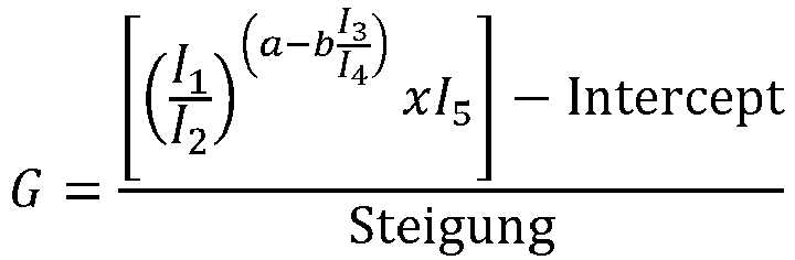 G die Hämatokrit-korrigierte Glukosekonzentration ist;I 1 der erste Prüfstrom ist;I 2 der zweite Prüfstrom ist;I 3 der dritte Prüfstrom ist;I 4 der vierte Prüfstrom ist;I 5 der fünfte Prüfstrom ist;a und b Abstimmparameter sind, die empirisch abgeleitet werden;Intercept ein Interceptwert ist, der aus einer linearen Regression eines Diagramms von
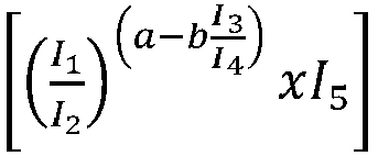 Steigung ein Steigungswert ist, der aus einer linearen Regression eines Diagramms von
- Verfahren zum Messen einer Glukosekonzentration in physiologischer Flüssigkeit eines Benutzers mit einem Teststreifen (200), der ein Substrat (205) enthält, das eine Referenzelektrode (210), eine erste Arbeitselektrode (212) und eine zweite Arbeitselektrode (214) aufweist, die mit einer Reagensschicht (218) mit einem Mediator beschichtet sind, wobei die Elektroden mit entsprechenden Kontaktflächen (211, 213, 215) verbunden sind:Anlegen einer Prüfspannung nach Aufbringen einer physiologischen Flüssigkeit auf die Elektroden;Messen eines ersten, zweiten, dritten, vierten und fünften Prüfstroms in ersten, zweiten, dritten, vierten und fünften diskreten Intervallen nach Anlegen der Prüfspannung durch das Analytenmessgerät; undBestimmen einer Hämatokrit-korrigierten Glukosekonzentration aus dem gemessenen ersten, zweiten, dritten, vierten und fünften Prüfstrom,wobei die Hämatokrit-korrigierte Glukosekonzentration ein Wert ist, der wie folgt erhalten wird:
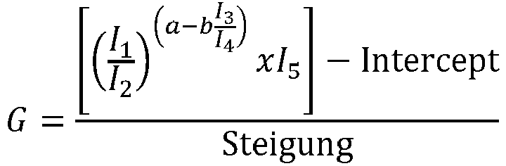 G die Hämatokrit-korrigierte Glukosekonzentration ist;I 1 der erste Prüfstrom ist;I 2 der zweite Prüfstrom ist;I 3 der dritte Prüfstrom ist;I 4 der vierte Prüfstrom ist;I 5 der fünfte Prüfstrom ist;a und b Abstimmparameter sind, die empirisch abgeleitet werden;Intercept ein Interceptwert ist, der aus einer linearen Regression eines Diagramms von
 Steigung ein Steigungswert ist, der aus einer linearen Regression eines Diagramms von
- Verfahren nach Anspruch 2, bei dem der erste Prüfstrom von etwa 0,98 bis etwa 1,00 Sekunden nach Beginn der Messung gemessen wird; der zweite Strom von etwa 1,09 bis etwa 2,00 Sekunden nach Beginn der Messung gemessen wird; der dritte Strom von etwa 2,43 bis etwa 2,45 Sekunden nach Beginn der Messung gemessen wird; der vierte Strom von etwa 2,61 bis etwa 2,63 Sekunden nach Beginn der Messung gemessen wird; der fünfte Strom von etwa 2,70 bis etwa 2,72 Sekunden nach Beginn der Messung gemessen wird.
- Verfahren nach Anspruch 3, bei dem der erste Prüfstrom von etwa 3,37 bis etwa 3,39 Sekunden nach einer Reaktionszeit gemessen wird; der zweite Strom von etwa 3,46 bis etwa 3,48 Sekunden nach einer Reaktionszeit gemessen wird; der dritte Strom von etwa 3,54 bis etwa 3,56 Sekunden nach einer Reaktionszeit gemessen wird; der vierte Strom von etwa 4,05 bis etwa 4,07 Sekunden nach einer Reaktionszeit gemessen wird; der fünfte Strom von etwa 4,08 bis etwa 4,10 Sekunden nach einer Reaktionszeit gemessen wird.
Applications Claiming Priority (3)
| Application Number | Priority Date | Filing Date | Title |
|---|---|---|---|
| US31947010P | 2010-03-31 | 2010-03-31 | |
| PCT/GB2011/000483 WO2011121292A1 (en) | 2010-03-31 | 2011-03-30 | Electrochemical analyte measurement method and system |
| EP11715595.2A EP2553441B1 (de) | 2010-03-31 | 2011-03-30 | Verfahren und system für elektrochemische analytmessung |
Related Parent Applications (3)
| Application Number | Title | Priority Date | Filing Date |
|---|---|---|---|
| EP11715595.2 Division | 2011-03-30 | ||
| EP11715595.2A Division-Into EP2553441B1 (de) | 2010-03-31 | 2011-03-30 | Verfahren und system für elektrochemische analytmessung |
| EP11715595.2A Division EP2553441B1 (de) | 2010-03-31 | 2011-03-30 | Verfahren und system für elektrochemische analytmessung |
Publications (3)
| Publication Number | Publication Date |
|---|---|
| EP2565638A2 EP2565638A2 (de) | 2013-03-06 |
| EP2565638A3 EP2565638A3 (de) | 2013-04-03 |
| EP2565638B1 true EP2565638B1 (de) | 2021-09-01 |
Family
ID=44072739
Family Applications (4)
| Application Number | Title | Priority Date | Filing Date |
|---|---|---|---|
| EP11715595.2A Active EP2553441B1 (de) | 2010-03-31 | 2011-03-30 | Verfahren und system für elektrochemische analytmessung |
| EP12195155.2A Not-in-force EP2565638B1 (de) | 2010-03-31 | 2011-03-30 | Electrochemisches analytmesssystem und analytmessverfahren |
| EP12195112A Withdrawn EP2565637A3 (de) | 2010-03-31 | 2011-03-30 | Analytmessverfahren und -system |
| EP12195075A Withdrawn EP2565636A3 (de) | 2010-03-31 | 2011-03-30 | Analytmessverfahren und -system |
Family Applications Before (1)
| Application Number | Title | Priority Date | Filing Date |
|---|---|---|---|
| EP11715595.2A Active EP2553441B1 (de) | 2010-03-31 | 2011-03-30 | Verfahren und system für elektrochemische analytmessung |
Family Applications After (2)
| Application Number | Title | Priority Date | Filing Date |
|---|---|---|---|
| EP12195112A Withdrawn EP2565637A3 (de) | 2010-03-31 | 2011-03-30 | Analytmessverfahren und -system |
| EP12195075A Withdrawn EP2565636A3 (de) | 2010-03-31 | 2011-03-30 | Analytmessverfahren und -system |
Country Status (11)
| Country | Link |
|---|---|
| US (3) | US8962270B2 (de) |
| EP (4) | EP2553441B1 (de) |
| JP (1) | JP5785247B2 (de) |
| KR (1) | KR20130014053A (de) |
| CN (1) | CN102918388B (de) |
| AU (1) | AU2011234255B2 (de) |
| BR (1) | BR112012024945A2 (de) |
| CA (1) | CA2794978C (de) |
| ES (1) | ES2764102T3 (de) |
| RU (1) | RU2573612C2 (de) |
| WO (1) | WO2011121292A1 (de) |
Families Citing this family (26)
| Publication number | Priority date | Publication date | Assignee | Title |
|---|---|---|---|---|
| US20060281187A1 (en) | 2005-06-13 | 2006-12-14 | Rosedale Medical, Inc. | Analyte detection devices and methods with hematocrit/volume correction and feedback control |
| EP1928316B1 (de) | 2005-09-30 | 2014-02-26 | Intuity Medical, Inc. | Kassette zur entnahme und analyse von körperflüssigkeiten mit mehreren stellen |
| US8801631B2 (en) | 2005-09-30 | 2014-08-12 | Intuity Medical, Inc. | Devices and methods for facilitating fluid transport |
| WO2009145920A1 (en) | 2008-05-30 | 2009-12-03 | Intuity Medical, Inc. | Body fluid sampling device -- sampling site interface |
| EP2299904B1 (de) | 2008-06-06 | 2019-09-11 | Intuity Medical, Inc. | Medizinisches messverfahren |
| JP5642066B2 (ja) | 2008-06-06 | 2014-12-17 | インテュイティ メディカル インコーポレイテッド | 体液の試料内に含まれている検体の存在または濃度を決定する検定を行う方法および装置 |
| EP2506768B1 (de) | 2009-11-30 | 2016-07-06 | Intuity Medical, Inc. | Vorrichtung und verfahren zur ausgabe eines kalibrierungsmaterials |
| KR20130014053A (ko) * | 2010-03-31 | 2013-02-06 | 라이프스캔 스코트랜드 리미티드 | 전기화학 분석물 측정 방법 및 시스템 |
| WO2012035297A1 (en) * | 2010-09-13 | 2012-03-22 | Lifescan Scotland Limited | Analyte measurement method and system with hematocrit compensation |
| RU2577366C2 (ru) * | 2010-09-28 | 2016-03-20 | Лайфскэн Скотлэнд Лимитед | Способ электрохимического измерения глюкозы с обнаружением ошибок |
| EP3901624B1 (de) | 2010-12-22 | 2024-01-31 | Roche Diabetes Care GmbH | Verfahren zur kompensation von fehlerquellen während elektrochemischer tests |
| CA2843945C (en) | 2011-08-03 | 2022-06-21 | Intuity Medical, Inc. | Devices and methods for body fluid sampling and analysis |
| US9903830B2 (en) * | 2011-12-29 | 2018-02-27 | Lifescan Scotland Limited | Accurate analyte measurements for electrochemical test strip based on sensed physical characteristic(s) of the sample containing the analyte |
| KR102035472B1 (ko) * | 2011-12-29 | 2019-10-23 | 라이프스캔 스코트랜드 리미티드 | 분석물을 함유한 샘플의 감지된 물리적 특성(들) 및 도출된 바이오센서 파라미터에 기초한 전기화학 검사 스트립을 위한 정확한 분석물 측정 |
| US9005426B2 (en) * | 2012-09-28 | 2015-04-14 | Cilag Gmbh International | System and method for determining hematocrit insensitive glucose concentration |
| US10101293B2 (en) * | 2013-08-09 | 2018-10-16 | The Board Of Trustees Of The Leland Stanford Junio | Sensing platform for transduction of information |
| US9243276B2 (en) * | 2013-08-29 | 2016-01-26 | Lifescan Scotland Limited | Method and system to determine hematocrit-insensitive glucose values in a fluid sample |
| US9459231B2 (en) | 2013-08-29 | 2016-10-04 | Lifescan Scotland Limited | Method and system to determine erroneous measurement signals during a test measurement sequence |
| US9383332B2 (en) * | 2013-09-24 | 2016-07-05 | Lifescan Scotland Limited | Analytical test strip with integrated battery |
| JP6258145B2 (ja) * | 2014-07-18 | 2018-01-10 | 株式会社東芝 | 微粒子検査システム及びその駆動方法 |
| EP3315964B1 (de) * | 2016-10-27 | 2023-08-30 | Industrial Technology Research Institute | Verfahren zur messung des hämatokrits und verfahren zum testen von blut |
| WO2018198008A1 (en) * | 2017-04-24 | 2018-11-01 | Abdolahad Mohammad | In-situ microbubbles generation for ultrasonic biomedical applications |
| EP3406193B1 (de) * | 2017-05-23 | 2021-12-08 | Roche Diabetes Care GmbH | Sensorsystem und verfahren zur herstellung davon |
| EP4004535A1 (de) * | 2019-07-24 | 2022-06-01 | LifeScan IP Holdings, LLC | Kontaminationsbestimmung von in analytmesssystemen verwendeten biosensoren |
| CN110954687B (zh) * | 2019-11-18 | 2022-06-07 | 深圳微点生物技术股份有限公司 | 一种用于凝血检测的方法与设备 |
| KR102691454B1 (ko) * | 2021-07-29 | 2024-08-05 | 경북대학교 산학협력단 | 대장암 진단용 통합 자기 전기화학장치 및 그 방법 |
Family Cites Families (22)
| Publication number | Priority date | Publication date | Assignee | Title |
|---|---|---|---|---|
| US6241862B1 (en) | 1996-02-14 | 2001-06-05 | Inverness Medical Technology, Inc. | Disposable test strips with integrated reagent/blood separation layer |
| JP4256588B2 (ja) * | 1998-05-20 | 2009-04-22 | アークレイ株式会社 | 統計的手法を用いた電気化学的測定方法および測定装置 |
| JP4050434B2 (ja) | 1999-11-29 | 2008-02-20 | 松下電器産業株式会社 | サンプルの弁別方法 |
| US6664776B2 (en) * | 2001-12-18 | 2003-12-16 | Otre Ab | Method and system for voltammetric characterization of a liquid sample |
| JP2004026217A (ja) | 2002-06-25 | 2004-01-29 | Kubota Corp | 物品搬送用の保持具 |
| US7132041B2 (en) | 2003-02-11 | 2006-11-07 | Bayer Healthcare Llc | Methods of determining the concentration of an analyte in a fluid test sample |
| JP2004264217A (ja) | 2003-03-03 | 2004-09-24 | Umax Data Systems Inc | バイオセンサの読取り値解析度を高める方法 |
| KR101427559B1 (ko) * | 2004-05-14 | 2014-08-07 | 바이엘 헬스케어 엘엘씨 | 생물학적 분석물의 검사를 위한 전압전류식 시스템 |
| JP5385607B2 (ja) * | 2005-07-20 | 2014-01-08 | バイエル・ヘルスケア・エルエルシー | ゲート化電流測定器 |
| US7749371B2 (en) | 2005-09-30 | 2010-07-06 | Lifescan, Inc. | Method and apparatus for rapid electrochemical analysis |
| US8066866B2 (en) * | 2005-10-17 | 2011-11-29 | Lifescan, Inc. | Methods for measuring physiological fluids |
| JP5018777B2 (ja) | 2006-07-05 | 2012-09-05 | パナソニック株式会社 | 液体試料測定方法および装置 |
| DE102006043718B4 (de) * | 2006-09-18 | 2014-12-31 | Alexander Adlassnig | Bestimmung von Wasserstoffperoxidkonzentrationen |
| ATE499450T1 (de) | 2006-10-05 | 2011-03-15 | Lifescan Scotland Ltd | Reagensformulierung mit rutheniumhexamin als vermittler für elektrochemische teststreifen |
| WO2008040998A2 (en) | 2006-10-05 | 2008-04-10 | Lifescan Scotland Limited | Systems and methods for determining a substantially hematocrit independent analyte concentration |
| ES2544353T3 (es) * | 2006-10-05 | 2015-08-28 | Lifescan Scotland Ltd | Métodos para determinar una concentración de analitos usando algoritmos de procesamiento de señales |
| EP2176652B1 (de) | 2007-07-26 | 2014-04-23 | Nipro Diagnostics, Inc. | System und verfahren zur bestimmung der analytkonzentration mittels zeitaufgelöster amperometrie |
| US8778168B2 (en) * | 2007-09-28 | 2014-07-15 | Lifescan, Inc. | Systems and methods of discriminating control solution from a physiological sample |
| US8603768B2 (en) | 2008-01-17 | 2013-12-10 | Lifescan, Inc. | System and method for measuring an analyte in a sample |
| US8551320B2 (en) | 2008-06-09 | 2013-10-08 | Lifescan, Inc. | System and method for measuring an analyte in a sample |
| US8545693B2 (en) * | 2009-09-29 | 2013-10-01 | Lifescan Scotland Limited | Analyte measurment method and system |
| KR20130014053A (ko) * | 2010-03-31 | 2013-02-06 | 라이프스캔 스코트랜드 리미티드 | 전기화학 분석물 측정 방법 및 시스템 |
-
2011
- 2011-03-30 KR KR1020127028013A patent/KR20130014053A/ko not_active Ceased
- 2011-03-30 ES ES11715595T patent/ES2764102T3/es active Active
- 2011-03-30 EP EP11715595.2A patent/EP2553441B1/de active Active
- 2011-03-30 EP EP12195155.2A patent/EP2565638B1/de not_active Not-in-force
- 2011-03-30 BR BR112012024945A patent/BR112012024945A2/pt not_active Application Discontinuation
- 2011-03-30 CN CN201180026678.1A patent/CN102918388B/zh not_active Expired - Fee Related
- 2011-03-30 RU RU2012146333/28A patent/RU2573612C2/ru active
- 2011-03-30 US US13/637,220 patent/US8962270B2/en not_active Expired - Fee Related
- 2011-03-30 AU AU2011234255A patent/AU2011234255B2/en not_active Ceased
- 2011-03-30 EP EP12195112A patent/EP2565637A3/de not_active Withdrawn
- 2011-03-30 JP JP2013501929A patent/JP5785247B2/ja not_active Expired - Fee Related
- 2011-03-30 EP EP12195075A patent/EP2565636A3/de not_active Withdrawn
- 2011-03-30 CA CA2794978A patent/CA2794978C/en not_active Expired - Fee Related
- 2011-03-30 WO PCT/GB2011/000483 patent/WO2011121292A1/en not_active Ceased
-
2015
- 2015-01-27 US US14/606,317 patent/US9500618B2/en not_active Expired - Fee Related
-
2016
- 2016-11-03 US US15/342,335 patent/US10429337B2/en active Active
Also Published As
| Publication number | Publication date |
|---|---|
| US8962270B2 (en) | 2015-02-24 |
| ES2764102T3 (es) | 2020-06-02 |
| EP2553441A1 (de) | 2013-02-06 |
| US10429337B2 (en) | 2019-10-01 |
| EP2565637A2 (de) | 2013-03-06 |
| JP2013524196A (ja) | 2013-06-17 |
| EP2565636A3 (de) | 2013-04-03 |
| EP2553441B1 (de) | 2019-10-23 |
| US20170074818A1 (en) | 2017-03-16 |
| EP2565637A3 (de) | 2013-04-03 |
| US9500618B2 (en) | 2016-11-22 |
| CA2794978C (en) | 2018-11-13 |
| CN102918388A (zh) | 2013-02-06 |
| AU2011234255B2 (en) | 2014-12-11 |
| WO2011121292A1 (en) | 2011-10-06 |
| EP2565638A2 (de) | 2013-03-06 |
| US20150136615A1 (en) | 2015-05-21 |
| EP2565636A2 (de) | 2013-03-06 |
| CA2794978A1 (en) | 2011-10-06 |
| EP2565638A3 (de) | 2013-04-03 |
| JP5785247B2 (ja) | 2015-09-24 |
| CN102918388B (zh) | 2015-11-25 |
| US20130095510A1 (en) | 2013-04-18 |
| RU2573612C2 (ru) | 2016-01-20 |
| KR20130014053A (ko) | 2013-02-06 |
| BR112012024945A2 (pt) | 2016-07-12 |
| AU2011234255A1 (en) | 2012-10-25 |
| RU2012146333A (ru) | 2014-05-10 |
Similar Documents
| Publication | Publication Date | Title |
|---|---|---|
| EP2565638B1 (de) | Electrochemisches analytmesssystem und analytmessverfahren | |
| EP2770063B1 (de) | Elektrochemisches Glucosemessverfahren mit Fehlererkennung | |
| EP2473847B1 (de) | Verfahren und vorrichtung zur glukosemessung | |
| EP2615976B1 (de) | Analytmessungsverfahren und system mit hämatokritkompensation | |
| AU2014262270B2 (en) | Electrochemical analyte measurement method and system | |
| HK1181851B (en) | Electrochemical analyte measurement system and method | |
| HK1179345A (en) | Electrochemical analyte measurement method and system | |
| HK1179345B (en) | Electrochemical analyte measurement method and system | |
| HK1181852A (en) | Electrochemical analyte measurement method and system | |
| HK1180763A (en) | Electrochemical analyte measurement method and system | |
| HK1181851A (en) | Electrochemical analyte measurement method and system | |
| HK1186950A (en) | Analyte measurement method and system with hematocrit compensation | |
| HK1186950B (en) | Analyte measurement method and system with hematocrit compensation | |
| HK40013207A (en) | Analyte measurement method with hematocrit compensation | |
| HK1201566B (en) | Glucose electrochemical measurement method with error detection |
Legal Events
| Date | Code | Title | Description |
|---|---|---|---|
| PUAL | Search report despatched |
Free format text: ORIGINAL CODE: 0009013 |
|
| PUAI | Public reference made under article 153(3) epc to a published international application that has entered the european phase |
Free format text: ORIGINAL CODE: 0009012 |
|
| AC | Divisional application: reference to earlier application |
Ref document number: 2553441 Country of ref document: EP Kind code of ref document: P |
|
| AK | Designated contracting states |
Kind code of ref document: A2 Designated state(s): AL AT BE BG CH CY CZ DE DK EE ES FI FR GB GR HR HU IE IS IT LI LT LU LV MC MK MT NL NO PL PT RO RS SE SI SK SM TR |
|
| AX | Request for extension of the european patent |
Extension state: BA ME |
|
| AK | Designated contracting states |
Kind code of ref document: A3 Designated state(s): AL AT BE BG CH CY CZ DE DK EE ES FI FR GB GR HR HU IE IS IT LI LT LU LV MC MK MT NL NO PL PT RO RS SE SI SK SM TR |
|
| AX | Request for extension of the european patent |
Extension state: BA ME |
|
| RIC1 | Information provided on ipc code assigned before grant |
Ipc: G01N 27/327 20060101AFI20130228BHEP |
|
| RIN1 | Information on inventor provided before grant (corrected) |
Inventor name: CRAGGS, ADAM Inventor name: MALECHA, MICHAEL |
|
| 17P | Request for examination filed |
Effective date: 20131002 |
|
| RBV | Designated contracting states (corrected) |
Designated state(s): AL AT BE BG CH CY CZ DE DK EE ES FI FR GB GR HR HU IE IS IT LI LT LU LV MC MK MT NL NO PL PT RO RS SE SI SK SM TR |
|
| REG | Reference to a national code |
Ref country code: HK Ref legal event code: DE Ref document number: 1181851 Country of ref document: HK |
|
| STAA | Information on the status of an ep patent application or granted ep patent |
Free format text: STATUS: EXAMINATION IS IN PROGRESS |
|
| 17Q | First examination report despatched |
Effective date: 20171020 |
|
| GRAP | Despatch of communication of intention to grant a patent |
Free format text: ORIGINAL CODE: EPIDOSNIGR1 |
|
| STAA | Information on the status of an ep patent application or granted ep patent |
Free format text: STATUS: GRANT OF PATENT IS INTENDED |
|
| RIC1 | Information provided on ipc code assigned before grant |
Ipc: G01N 27/327 20060101AFI20210222BHEP Ipc: G01N 33/49 20060101ALI20210222BHEP |
|
| INTG | Intention to grant announced |
Effective date: 20210311 |
|
| GRAS | Grant fee paid |
Free format text: ORIGINAL CODE: EPIDOSNIGR3 |
|
| GRAA | (expected) grant |
Free format text: ORIGINAL CODE: 0009210 |
|
| STAA | Information on the status of an ep patent application or granted ep patent |
Free format text: STATUS: THE PATENT HAS BEEN GRANTED |
|
| AC | Divisional application: reference to earlier application |
Ref document number: 2553441 Country of ref document: EP Kind code of ref document: P |
|
| AK | Designated contracting states |
Kind code of ref document: B1 Designated state(s): AL AT BE BG CH CY CZ DE DK EE ES FI FR GB GR HR HU IE IS IT LI LT LU LV MC MK MT NL NO PL PT RO RS SE SI SK SM TR |
|
| REG | Reference to a national code |
Ref country code: GB Ref legal event code: FG4D |
|
| REG | Reference to a national code |
Ref country code: CH Ref legal event code: EP Ref country code: AT Ref legal event code: REF Ref document number: 1426734 Country of ref document: AT Kind code of ref document: T Effective date: 20210915 |
|
| REG | Reference to a national code |
Ref country code: DE Ref legal event code: R096 Ref document number: 602011071710 Country of ref document: DE |
|
| REG | Reference to a national code |
Ref country code: IE Ref legal event code: FG4D |
|
| REG | Reference to a national code |
Ref country code: LT Ref legal event code: MG9D |
|
| REG | Reference to a national code |
Ref country code: NL Ref legal event code: MP Effective date: 20210901 |
|
| PG25 | Lapsed in a contracting state [announced via postgrant information from national office to epo] |
Ref country code: RS Free format text: LAPSE BECAUSE OF FAILURE TO SUBMIT A TRANSLATION OF THE DESCRIPTION OR TO PAY THE FEE WITHIN THE PRESCRIBED TIME-LIMIT Effective date: 20210901 Ref country code: NO Free format text: LAPSE BECAUSE OF FAILURE TO SUBMIT A TRANSLATION OF THE DESCRIPTION OR TO PAY THE FEE WITHIN THE PRESCRIBED TIME-LIMIT Effective date: 20211201 Ref country code: FI Free format text: LAPSE BECAUSE OF FAILURE TO SUBMIT A TRANSLATION OF THE DESCRIPTION OR TO PAY THE FEE WITHIN THE PRESCRIBED TIME-LIMIT Effective date: 20210901 Ref country code: ES Free format text: LAPSE BECAUSE OF FAILURE TO SUBMIT A TRANSLATION OF THE DESCRIPTION OR TO PAY THE FEE WITHIN THE PRESCRIBED TIME-LIMIT Effective date: 20210901 Ref country code: BG Free format text: LAPSE BECAUSE OF FAILURE TO SUBMIT A TRANSLATION OF THE DESCRIPTION OR TO PAY THE FEE WITHIN THE PRESCRIBED TIME-LIMIT Effective date: 20211201 Ref country code: LT Free format text: LAPSE BECAUSE OF FAILURE TO SUBMIT A TRANSLATION OF THE DESCRIPTION OR TO PAY THE FEE WITHIN THE PRESCRIBED TIME-LIMIT Effective date: 20210901 Ref country code: HR Free format text: LAPSE BECAUSE OF FAILURE TO SUBMIT A TRANSLATION OF THE DESCRIPTION OR TO PAY THE FEE WITHIN THE PRESCRIBED TIME-LIMIT Effective date: 20210901 Ref country code: SE Free format text: LAPSE BECAUSE OF FAILURE TO SUBMIT A TRANSLATION OF THE DESCRIPTION OR TO PAY THE FEE WITHIN THE PRESCRIBED TIME-LIMIT Effective date: 20210901 |
|
| REG | Reference to a national code |
Ref country code: AT Ref legal event code: MK05 Ref document number: 1426734 Country of ref document: AT Kind code of ref document: T Effective date: 20210901 |
|
| PG25 | Lapsed in a contracting state [announced via postgrant information from national office to epo] |
Ref country code: PL Free format text: LAPSE BECAUSE OF FAILURE TO SUBMIT A TRANSLATION OF THE DESCRIPTION OR TO PAY THE FEE WITHIN THE PRESCRIBED TIME-LIMIT Effective date: 20210901 Ref country code: LV Free format text: LAPSE BECAUSE OF FAILURE TO SUBMIT A TRANSLATION OF THE DESCRIPTION OR TO PAY THE FEE WITHIN THE PRESCRIBED TIME-LIMIT Effective date: 20210901 Ref country code: GR Free format text: LAPSE BECAUSE OF FAILURE TO SUBMIT A TRANSLATION OF THE DESCRIPTION OR TO PAY THE FEE WITHIN THE PRESCRIBED TIME-LIMIT Effective date: 20211202 |
|
| PG25 | Lapsed in a contracting state [announced via postgrant information from national office to epo] |
Ref country code: AT Free format text: LAPSE BECAUSE OF FAILURE TO SUBMIT A TRANSLATION OF THE DESCRIPTION OR TO PAY THE FEE WITHIN THE PRESCRIBED TIME-LIMIT Effective date: 20210901 |
|
| PG25 | Lapsed in a contracting state [announced via postgrant information from national office to epo] |
Ref country code: IS Free format text: LAPSE BECAUSE OF FAILURE TO SUBMIT A TRANSLATION OF THE DESCRIPTION OR TO PAY THE FEE WITHIN THE PRESCRIBED TIME-LIMIT Effective date: 20220101 Ref country code: SM Free format text: LAPSE BECAUSE OF FAILURE TO SUBMIT A TRANSLATION OF THE DESCRIPTION OR TO PAY THE FEE WITHIN THE PRESCRIBED TIME-LIMIT Effective date: 20210901 Ref country code: SK Free format text: LAPSE BECAUSE OF FAILURE TO SUBMIT A TRANSLATION OF THE DESCRIPTION OR TO PAY THE FEE WITHIN THE PRESCRIBED TIME-LIMIT Effective date: 20210901 Ref country code: RO Free format text: LAPSE BECAUSE OF FAILURE TO SUBMIT A TRANSLATION OF THE DESCRIPTION OR TO PAY THE FEE WITHIN THE PRESCRIBED TIME-LIMIT Effective date: 20210901 Ref country code: PT Free format text: LAPSE BECAUSE OF FAILURE TO SUBMIT A TRANSLATION OF THE DESCRIPTION OR TO PAY THE FEE WITHIN THE PRESCRIBED TIME-LIMIT Effective date: 20220103 Ref country code: NL Free format text: LAPSE BECAUSE OF FAILURE TO SUBMIT A TRANSLATION OF THE DESCRIPTION OR TO PAY THE FEE WITHIN THE PRESCRIBED TIME-LIMIT Effective date: 20210901 Ref country code: EE Free format text: LAPSE BECAUSE OF FAILURE TO SUBMIT A TRANSLATION OF THE DESCRIPTION OR TO PAY THE FEE WITHIN THE PRESCRIBED TIME-LIMIT Effective date: 20210901 Ref country code: CZ Free format text: LAPSE BECAUSE OF FAILURE TO SUBMIT A TRANSLATION OF THE DESCRIPTION OR TO PAY THE FEE WITHIN THE PRESCRIBED TIME-LIMIT Effective date: 20210901 Ref country code: AL Free format text: LAPSE BECAUSE OF FAILURE TO SUBMIT A TRANSLATION OF THE DESCRIPTION OR TO PAY THE FEE WITHIN THE PRESCRIBED TIME-LIMIT Effective date: 20210901 |
|
| REG | Reference to a national code |
Ref country code: DE Ref legal event code: R097 Ref document number: 602011071710 Country of ref document: DE |
|
| PLBE | No opposition filed within time limit |
Free format text: ORIGINAL CODE: 0009261 |
|
| STAA | Information on the status of an ep patent application or granted ep patent |
Free format text: STATUS: NO OPPOSITION FILED WITHIN TIME LIMIT |
|
| PG25 | Lapsed in a contracting state [announced via postgrant information from national office to epo] |
Ref country code: IT Free format text: LAPSE BECAUSE OF FAILURE TO SUBMIT A TRANSLATION OF THE DESCRIPTION OR TO PAY THE FEE WITHIN THE PRESCRIBED TIME-LIMIT Effective date: 20210901 Ref country code: DK Free format text: LAPSE BECAUSE OF FAILURE TO SUBMIT A TRANSLATION OF THE DESCRIPTION OR TO PAY THE FEE WITHIN THE PRESCRIBED TIME-LIMIT Effective date: 20210901 |
|
| 26N | No opposition filed |
Effective date: 20220602 |
|
| PG25 | Lapsed in a contracting state [announced via postgrant information from national office to epo] |
Ref country code: SI Free format text: LAPSE BECAUSE OF FAILURE TO SUBMIT A TRANSLATION OF THE DESCRIPTION OR TO PAY THE FEE WITHIN THE PRESCRIBED TIME-LIMIT Effective date: 20210901 |
|
| REG | Reference to a national code |
Ref country code: DE Ref legal event code: R119 Ref document number: 602011071710 Country of ref document: DE |
|
| PG25 | Lapsed in a contracting state [announced via postgrant information from national office to epo] |
Ref country code: MC Free format text: LAPSE BECAUSE OF FAILURE TO SUBMIT A TRANSLATION OF THE DESCRIPTION OR TO PAY THE FEE WITHIN THE PRESCRIBED TIME-LIMIT Effective date: 20210901 |
|
| REG | Reference to a national code |
Ref country code: CH Ref legal event code: PL |
|
| GBPC | Gb: european patent ceased through non-payment of renewal fee |
Effective date: 20220330 |
|
| REG | Reference to a national code |
Ref country code: BE Ref legal event code: MM Effective date: 20220331 |
|
| PG25 | Lapsed in a contracting state [announced via postgrant information from national office to epo] |
Ref country code: LU Free format text: LAPSE BECAUSE OF NON-PAYMENT OF DUE FEES Effective date: 20220330 Ref country code: LI Free format text: LAPSE BECAUSE OF NON-PAYMENT OF DUE FEES Effective date: 20220331 Ref country code: IE Free format text: LAPSE BECAUSE OF NON-PAYMENT OF DUE FEES Effective date: 20220330 Ref country code: GB Free format text: LAPSE BECAUSE OF NON-PAYMENT OF DUE FEES Effective date: 20220330 Ref country code: FR Free format text: LAPSE BECAUSE OF NON-PAYMENT OF DUE FEES Effective date: 20220331 Ref country code: DE Free format text: LAPSE BECAUSE OF NON-PAYMENT OF DUE FEES Effective date: 20221001 Ref country code: CH Free format text: LAPSE BECAUSE OF NON-PAYMENT OF DUE FEES Effective date: 20220331 |
|
| PG25 | Lapsed in a contracting state [announced via postgrant information from national office to epo] |
Ref country code: BE Free format text: LAPSE BECAUSE OF NON-PAYMENT OF DUE FEES Effective date: 20220331 |
|
| PG25 | Lapsed in a contracting state [announced via postgrant information from national office to epo] |
Ref country code: HU Free format text: LAPSE BECAUSE OF FAILURE TO SUBMIT A TRANSLATION OF THE DESCRIPTION OR TO PAY THE FEE WITHIN THE PRESCRIBED TIME-LIMIT; INVALID AB INITIO Effective date: 20110330 |
|
| PG25 | Lapsed in a contracting state [announced via postgrant information from national office to epo] |
Ref country code: MK Free format text: LAPSE BECAUSE OF FAILURE TO SUBMIT A TRANSLATION OF THE DESCRIPTION OR TO PAY THE FEE WITHIN THE PRESCRIBED TIME-LIMIT Effective date: 20210901 Ref country code: CY Free format text: LAPSE BECAUSE OF FAILURE TO SUBMIT A TRANSLATION OF THE DESCRIPTION OR TO PAY THE FEE WITHIN THE PRESCRIBED TIME-LIMIT Effective date: 20210901 |
|
| PG25 | Lapsed in a contracting state [announced via postgrant information from national office to epo] |
Ref country code: TR Free format text: LAPSE BECAUSE OF FAILURE TO SUBMIT A TRANSLATION OF THE DESCRIPTION OR TO PAY THE FEE WITHIN THE PRESCRIBED TIME-LIMIT Effective date: 20210901 |
|
| PG25 | Lapsed in a contracting state [announced via postgrant information from national office to epo] |
Ref country code: MT Free format text: LAPSE BECAUSE OF FAILURE TO SUBMIT A TRANSLATION OF THE DESCRIPTION OR TO PAY THE FEE WITHIN THE PRESCRIBED TIME-LIMIT Effective date: 20210901 |