EP2565659A2 - Système de détection de défaillance pour un générateur - Google Patents
Système de détection de défaillance pour un générateur Download PDFInfo
- Publication number
- EP2565659A2 EP2565659A2 EP12182342A EP12182342A EP2565659A2 EP 2565659 A2 EP2565659 A2 EP 2565659A2 EP 12182342 A EP12182342 A EP 12182342A EP 12182342 A EP12182342 A EP 12182342A EP 2565659 A2 EP2565659 A2 EP 2565659A2
- Authority
- EP
- European Patent Office
- Prior art keywords
- generator
- voltage
- power converter
- breaker
- control logic
- Prior art date
- Legal status (The legal status is an assumption and is not a legal conclusion. Google has not performed a legal analysis and makes no representation as to the accuracy of the status listed.)
- Granted
Links
- 238000001514 detection method Methods 0.000 title claims abstract description 34
- 238000012806 monitoring device Methods 0.000 claims abstract description 53
- 238000012360 testing method Methods 0.000 claims abstract description 22
- 238000004891 communication Methods 0.000 claims abstract description 9
- 238000012544 monitoring process Methods 0.000 claims description 11
- 230000001360 synchronised effect Effects 0.000 claims description 5
- 230000003213 activating effect Effects 0.000 claims description 4
- 230000004907 flux Effects 0.000 claims description 3
- 238000013459 approach Methods 0.000 description 11
- 238000010586 diagram Methods 0.000 description 7
- 238000009987 spinning Methods 0.000 description 3
- 239000003990 capacitor Substances 0.000 description 2
- 230000009466 transformation Effects 0.000 description 2
- 230000004075 alteration Effects 0.000 description 1
- 238000006243 chemical reaction Methods 0.000 description 1
- 230000001419 dependent effect Effects 0.000 description 1
- 230000005611 electricity Effects 0.000 description 1
- 230000006698 induction Effects 0.000 description 1
- 230000002045 lasting effect Effects 0.000 description 1
- 238000012423 maintenance Methods 0.000 description 1
- 238000013021 overheating Methods 0.000 description 1
- 238000012163 sequencing technique Methods 0.000 description 1
- 238000006467 substitution reaction Methods 0.000 description 1
Images


Classifications
-
- G—PHYSICS
- G01—MEASURING; TESTING
- G01R—MEASURING ELECTRIC VARIABLES; MEASURING MAGNETIC VARIABLES
- G01R31/00—Arrangements for testing electric properties; Arrangements for locating electric faults; Arrangements for electrical testing characterised by what is being tested not provided for elsewhere
- G01R31/34—Testing dynamo-electric machines
- G01R31/343—Testing dynamo-electric machines in operation
-
- F—MECHANICAL ENGINEERING; LIGHTING; HEATING; WEAPONS; BLASTING
- F05—INDEXING SCHEMES RELATING TO ENGINES OR PUMPS IN VARIOUS SUBCLASSES OF CLASSES F01-F04
- F05B—INDEXING SCHEME RELATING TO WIND, SPRING, WEIGHT, INERTIA OR LIKE MOTORS, TO MACHINES OR ENGINES FOR LIQUIDS COVERED BY SUBCLASSES F03B, F03D AND F03G
- F05B2220/00—Application
- F05B2220/70—Application in combination with
- F05B2220/706—Application in combination with an electrical generator
- F05B2220/7068—Application in combination with an electrical generator equipped with permanent magnets
-
- F—MECHANICAL ENGINEERING; LIGHTING; HEATING; WEAPONS; BLASTING
- F05—INDEXING SCHEMES RELATING TO ENGINES OR PUMPS IN VARIOUS SUBCLASSES OF CLASSES F01-F04
- F05B—INDEXING SCHEME RELATING TO WIND, SPRING, WEIGHT, INERTIA OR LIKE MOTORS, TO MACHINES OR ENGINES FOR LIQUIDS COVERED BY SUBCLASSES F03B, F03D AND F03G
- F05B2260/00—Function
- F05B2260/80—Diagnostics
-
- F—MECHANICAL ENGINEERING; LIGHTING; HEATING; WEAPONS; BLASTING
- F05—INDEXING SCHEMES RELATING TO ENGINES OR PUMPS IN VARIOUS SUBCLASSES OF CLASSES F01-F04
- F05B—INDEXING SCHEME RELATING TO WIND, SPRING, WEIGHT, INERTIA OR LIKE MOTORS, TO MACHINES OR ENGINES FOR LIQUIDS COVERED BY SUBCLASSES F03B, F03D AND F03G
- F05B2270/00—Control
- F05B2270/30—Control parameters, e.g. input parameters
- F05B2270/327—Rotor or generator speeds
-
- F—MECHANICAL ENGINEERING; LIGHTING; HEATING; WEAPONS; BLASTING
- F05—INDEXING SCHEMES RELATING TO ENGINES OR PUMPS IN VARIOUS SUBCLASSES OF CLASSES F01-F04
- F05B—INDEXING SCHEME RELATING TO WIND, SPRING, WEIGHT, INERTIA OR LIKE MOTORS, TO MACHINES OR ENGINES FOR LIQUIDS COVERED BY SUBCLASSES F03B, F03D AND F03G
- F05B2270/00—Control
- F05B2270/30—Control parameters, e.g. input parameters
- F05B2270/337—Electrical grid status parameters, e.g. voltage, frequency or power demand
-
- G—PHYSICS
- G01—MEASURING; TESTING
- G01R—MEASURING ELECTRIC VARIABLES; MEASURING MAGNETIC VARIABLES
- G01R31/00—Arrangements for testing electric properties; Arrangements for locating electric faults; Arrangements for electrical testing characterised by what is being tested not provided for elsewhere
- G01R31/40—Testing power supplies
- G01R31/42—AC power supplies
Definitions
- the subject matter disclosed herein relates to a fault detection system, and more specifically to a fault detection system including a generator and a power converter that is selectively connected to the generator.
- Wind turbines are one alternative to conventional sources of energy.
- a wind turbine includes multiple blades that are connected to a rotor, where spinning of the blades by wind spins a shaft of the rotor.
- the rotor is connected to a generator that generates electricity.
- Some wind turbines include a gearbox that couples the rotor to the generator.
- Various types of generators are employed in wind turbines such as, for example, induction machines and separately excited synchronous machines.
- one type of generator that may be employed is a permanent magnet generator.
- the permanent magnet generator allows for higher efficiency but, because the permanent magnet generator is excited by permanent magnets, the permanent magnet generator is almost always capable of producing voltage when spinning. Thus, as long as the permanent magnet generator is spinning, voltage will typically be produced. However, a fault may occur on the output of the permanent magnet generator while voltage is being produced.
- a breaker may be provided to the output of the generator to generally prevent the current flow in the event of a fault.
- a power converter system may also be employed to convert the variable frequency electrical output power of the generator to an AC electrical power that matches the frequency of an electrical grid.
- the power converter is not activated.
- the power converter may not be activated if there is not adequate wind, maintenance work is being performed on the wind turbine, or in the event the wind turbine is nonoperational.
- a fault may occur between the cables that connect the generator to the power converter.
- the fault may be a short or an open circuit.
- the power converter In the event the power converter is activated, detection of a fault between the generator and the power converter is typically relatively simple to detect. While operating, both the power converter and the breakers an internal trip relay will detect the fault. The power converter will shut down and the breaker will open. However, in the event the power converter is not activated, this fault may go undetected. When a generator breaker is in a closed position, the power converter may or may not be activated.
- One approach for detecting a fault between the generator and the power converter when the power converter is not activated but the breaker is closed involves employing an internal trip relay in the generator main circuit breaker. However, the internal trip relay may not always be reliable at lower frequencies, and may also be prone to overheating while the power converter is activated due to the current harmonics produced by the power converter.
- a fault detection system includes a generator, a power converter, a breaker, a current monitoring device, and a control module to detect a fault when the breaker is in the open position.
- the power converter is selectively connected to the generator and is selectively activated to produce a test voltage.
- the breaker is located between the generator and the power converter for selectively connecting the generator to the power converter.
- the breaker includes an open position and a closed position.
- the current monitoring device is located between the generator and the power converter.
- the current monitoring device measures a line current between the generator and the power converter.
- the control module is in communication with the current monitoring device and the power converter.
- the control module has a memory with a threshold current value.
- the control module includes control logic for monitoring the breaker to determine if the breaker is in one of the open position and the closed position.
- the control module includes control logic for activating the power converter to produce the test voltage if the breaker is in the open position.
- the control module includes control logic for monitoring the current monitoring device for the line current.
- the control module includes control logic for determining if the line current is greater than the threshold current during a period of time while the test voltage is being produced.
- the control module includes control logic for determining that a fault is present if the breaker is in the open position and if the line current is greater than the threshold current.
- the control module includes control logic for maintaining the breakers in the open position if the fault is detected.
- a voltage monitoring device is provided between the generator and the power converter for measuring a line voltage, and the control module is in communication with the voltage monitoring device.
- a wind power plant having a fault detection system having a wind turbine, a gearbox connected to the wind turbine through a shaft, a generator connected to the shaft, a power converter, a breaker, a current monitoring device, a voltage monitoring device, and a control module.
- the power converter is selectively connected to the generator for being selectively activated to produce a test voltage.
- the breaker is located between the generator and the power converter for selectively connecting the generator to the power converter.
- the breaker includes an open position and a closed position.
- the current monitoring device is located between the generator and the power converter.
- the current monitoring device measures a line current.
- the voltage monitoring device is provided between the generator and the power converter for measuring a line voltage.
- the control module is in communication with the current monitoring device, the voltage monitoring device, the generator, the breaker and the power converter.
- the control module has a memory with a threshold current, a threshold voltage, and an expected voltage stored therein.
- the control module includes control logic for monitoring the breaker to determine if the breaker is in one of the open position and the closed position.
- the control module includes control logic for activating the power converter to produce the test voltage if the breaker is in the open position.
- the control module includes control logic for monitoring the current monitoring device for the line current.
- the control module includes control logic for determining if the line current is greater than the threshold current during a period of time while the test voltage is being produced.
- the control module includes control logic for determining that a fault is present if the breaker is in the open position and if the line current is greater than the threshold current or if the line voltage differs from the expected voltage by a specified voltage value.
- the control module includes control logic for calculating a measured voltage of the generator.
- the measured voltage of the generator is based on the line voltage, the line current, a cable resistance value, a cable inductance value, an internal inductance of the power converter and at least one parameter of the generator.
- the control module includes control logic for calculating an estimated voltage of the generator.
- the estimated voltage of the generator is based on the rotational speed of the generator, the line current, and the at least one parameter of the generator.
- the control module includes control logic for calculating a magnitude of the measured voltage of the generator and a magnitude of the estimated voltage of the generator.
- the control module includes control logic for determining the difference between the magnitude of the measured voltage of the generator and the magnitude of the estimated voltage of the generator.
- the control module includes control logic for determining a generator fault is present if the difference between the magnitude of the estimated voltage of the generator and the magnitude of the measured voltage of the generator is greater than the threshold voltage, and if the breaker is in the closed position.
- module and sub-module refer to an application specific integrated circuit (ASIC), an electronic circuit, a processor (shared, dedicated, or group) and memory that executes one or more software or firmware programs, a combinational logic circuit, and/or other suitable components that provide the described functionality.
- ASIC application specific integrated circuit
- processor shared, dedicated, or group
- memory that executes one or more software or firmware programs
- combinational logic circuit and/or other suitable components that provide the described functionality.
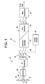
- the wind power plant 10 includes a wind turbine 20, a gearbox 22, a generator 24, a main power convertor 26, a converter controller 28, and a main transformer 30.
- the wind turbine 20 includes a hub 40 and a plurality of rotor blades 42 that are connected to the hub 40.
- a shaft 44 transfers energy from the wind turbine 20 to the generator 24 through the gearbox 22.
- the rotational speed of the shaft 44 is dependent on wind speed.
- the generator 24 is typically any type of machine that converts the mechanical energy from the shaft 44 into electrical energy such as, for example, a permanent magnet generator.
- a set of three connections 46 of the generator 24 are connected to the main power converter 26, and are labeled as 'A', 'B' and 'C'.
- Each of the connections 46 also include a breaker 48 for selectively interrupting the flow of current between the generator 24 and the main power converter 26.
- the breaker 48 may be a three-phase breaker.
- a fault detection system 50 is employed for detecting faults between the generator 24 and the main power converter 26.
- the fault detection system 50 may be able to detect a short or open circuit condition between the generator 24 and the main power converter 26.
- the fault detection system 50 may also determine if a tachometer 66 (shown in FIG. 2 ) measuring the rotational speed of the generator 24 is not functioning.
- FIG. 1 illustrates a wind power plant 10, it is to be understood that the generator 24 and the main power convertor 26 may be used in other applications as well.
- the main power convertor 26 generally includes circuitry for converting the variable frequency AC voltage from the generator 24 into a voltage that may be supplied to an AC grid (not shown). Specifically, the main power converter 26 is selectively activated to produce an output voltage, which is the AC voltage supplied to the AC grid.
- the main power converter 26 may include various power switching devices such as, for example, insulated gate bipolar transistors (IGBTs) or integrated gate-commutated thyristors (IGCTs).
- the power converter 26 includes a generator side converter 52 and a grid or line side converter 54.
- the generator side converter 52 receives an AC input voltage from the generator 24 and provides for conversion of the AC input voltage into a DC voltage.
- the generator side converter 52 provides the DC voltage to the line side converter 54 through a DC bus that includes a DC link capacitor 60 (shown in FIG. 2 ).
- the grid side converter 54 converts the DC voltage to an AC output voltage that is fed to the AC grid (not shown).
- Breaker 48 includes a closed position as well as an open position. In the closed position, current may flow in the connections 46 between the generator 24 and the main power converter 26. In the open position, current is generally unable to flow in the connections 46 between the generator 24 and the main power converter 26. Thus, the breaker 48 selectively connects the generator 24 to the main power converter 26.
- FIG. 2 is a single line diagram of a portion of the wind turbine 10 including the fault detection system 50.
- a current monitoring device 62 and a voltage monitoring device 64 are each located between the generator 24 and the main power converter 26.
- the current monitoring device 62 measures a line current of the connection 46 between the generator 24 and the main power converter 26.
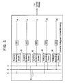
- FIG. 3 an illustration of three current monitoring devices 62 measuring the specific line currents associated with connections 'A', 'B' and 'C' is shown.
- the voltage monitoring device 64 measures a line voltage of the connection 46 between the generator 24 and the main power converter 26.
- An illustration of two voltage monitoring devices 64 is also shown in detail in FIG. 3 .
- the current monitoring device 62 and the voltage monitoring device 64 may be located at the terminals of the main power converter 26 to measure the current and voltage at the main power converter 26.
- the control module 28 is in communication with the generator side converter 52, the line side converter 54, the current monitoring device 62, the voltage monitoring device 64, the breaker 48 and an encoder or tachometer 66 of the generator 24.
- the tachometer 66 is used to monitor the rotational speed of the generator 24.
- the control module 28 includes control logic for determining if a fault exists in the connection 46 between the generator 24 and the main power converter 26, within the main power converter 26, with the tachometer 66, a fault in the generator 24 or between the generator 24 and the breaker 48 when the breaker 48 is closed.
- the control module 28 includes a memory.
- the memory of the control module stores a threshold current, a threshold voltage, and an expected voltage V Expected , which are used to determine if a fault exists.
- the threshold current value may range from about zero to about 300 Amps
- the threshold voltage value may range from about 150 to about 600 Volts.
- the fault detection system 50 determines if a fault exists in the event the breaker 48 is in the open position.
- the control module 28 includes control logic for determining if there is a short circuit condition either within the main power converter 26 or between the main power converter 26 and the breaker 48.
- the control module 28 also includes control logic for determining if a fault condition exists if the breaker 48 is in the closed position, and where the main power converter 26 may or may not be supplying output voltage to the generator 24.
- each of the connections 'A', 'B' and 'C' include a current monitoring device 62 and at least one voltage monitoring device 64.
- the output of the current monitoring devices 62 include I A , I B , and I C , where I A is the measured current in line 'A', I B is the current in line 'B', and I C is the current in line 'C'.
- the output of the voltage monitoring devices 64 include V AB , and V BC , where V AB is the measured voltage that appears between lines 'A' and 'B', and V BC is the voltage that appears between lines 'B' and 'C'.
- V AB is the measured voltage that appears between lines 'A' and 'B'
- V BC is the voltage that appears between lines 'B' and 'C'.
- the values I A , I B , Ic, V AB , and V BC are sent to the control module 28.
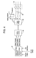
- FIG. 4 is a block diagram of an approach for determining if a fault condition exists if the breakers 48 are in the open position.
- a test sequencer 67 is provided.
- the test sequencer 67 may be part of the control module 28 (shown in FIG. 2 ). Alternatively, in another embodiment the test sequencer 67 is a stand-alone unit.
- the control module 28 includes control logic for monitoring the current monitoring device 62 for the line current and the voltage monitoring device 64 for the line voltage.
- the control module also includes control logic for monitoring the breaker 48 to determine if the breaker 48 is in the open position or the closed position.
- the control module 28 includes control logic for determining a DC link voltage by monitoring the DC link capacitor 60.
- the control module also includes a line inductance value that is specific to the system and is saved in the memory of the control module 28.
- the control module 28 includes control logic for sending signals to the test sequencer 67 indicating a breaker position, the DC link voltage, and the line inductance.
- the test sequencer 67 includes control logic for calculating a Gating Command signal for a specific duration of time.
- the specific duration of time is indicated in FIG. 4 as a Gating Duration T.
- the Gating Command signal is applied to each of the connections 46 that are denoted as 'A', 'B' and 'C' in a sequencing fashion.
- the Gating Command signal is first sent to the connection 'A'. Then, the Gating Command signal is sent the connection 'B'. Then, the Gating Command signal is sent to the connection 'C'.
- Voltage pulses are also produced by simultaneously gating two phases, for example a voltage pulse produced by connections 'A' and 'B', connections 'B' and 'C', and connections 'C' and 'A'.
- a block 68 labeled Gating Control receives the Gating Command from the test sequencer 67, and sends a command to the Power Bridge 69 to create a test voltage that is sent through the connections 46.
- the test voltage is a voltage pulse V.
- the Power Bridge 69 is the part of the control module 28 that contains various power switching devices (not shown) such as, for example IGBTs or IGCTs, which create the voltage pulse V.
- the voltage pulse V is then impressed on one or more of the connections 46 labeled 'A', 'B', or 'C'.
- the voltage pulse V is a voltage pulse that is configured for lasting for a period of time that is the Gating Duration T (sent from the test sequencer 67).
- the magnitude of the voltage pulse V is the expected voltage V Expected that is saved in the memory of the control module 28 but with some difference due to the tolerances of the electronics, and is denoted as V command .
- the current monitoring device 62 and the voltage monitoring device 64 are in communication with the connections 46 and measure the line current and the line voltage to determine if a fault condition is present during the Gating Duration T.
- the control module 28 includes control logic for determining if the line current is greater than the threshold current saved in the memory of the control module 28 when the voltage pulse V is sent. In the event that the line current is greater than the threshold current, the control module 28 includes control logic for indicating that a fault condition exists. That is, a short circuit is present either in the main power converter 26 or between the main power converter 26 and the breaker 48.
- the control module 28 also includes control logic for determining if the line voltage is a different value than the expected voltage V Expected when the voltage pulse V is sent. Specifically, if the line voltage varies by more than a specified voltage value from the expected voltage V Expected , this is an indication that a fault condition exists. For example, in one embodiment, if the line voltage varies by more than about 25% of the expected voltage V Expected , this is an indication that a fault condition exists, however it is to be understood that other variations may occur as well. In the event a fault condition is detected, the control module 28 includes control logic for maintaining the breakers 48 in the open position.
- FIG. 5 is a block diagram of an approach for determining if a fault condition exists that is executed by the control module 28 (shown in FIG. 2 ).
- the breakers 48 are in the closed position and the main power converter 26 may or may not be supplying output voltage to the generator 24.
- the values I A , I B , I C , V AB , V BC and the rotational speed of the generator 24 (shown in FIGS. 1-2 ), which is denoted as SpeedGen Tach , are used in the approach.
- the tachometer 66 is used to monitor the rotational speed of the generator 24. Turning back to FIG.
- the control module 28 includes control logic for receiving the measured voltages V AB and V BC .
- the measured voltages V AB and V BC represent the voltages that are either measured between the generator 24 and the main power converter 26 at the connections 46 (shown in FIG. 2 ), or alternatively at the terminals of the main power converter 26.
- the control module 28 includes control logic for providing the measured voltages V AB and V BC to a demodulator 70.
- the demodulator 70 includes control logic for converting the measured voltages V AB and V BC into a DC reference frame.
- the control module 28 includes control logic for converting the measured voltages V AB and V BC that are in a stationary three-phase frame into a rotating dq0 frame, where variables 'd' and 'q' are DC quantities.
- the control module 28 may use Park's Transformation (also referred to as direct-quadrature-zero transformation) to convert the measured voltages V AB and V BC into DC reference measured voltages V DCONV and V QCONV .
- the control module 28 further includes control logic for calculating measured voltages of the generator 24 (shown in FIGS. 1-2 ) in block 72.
- the measured voltages of the generator 24 are denoted as V DgenMeas and V QgenMeas , and are based on and are based on the DC reference measured voltages V DCONV and V QCONV , the measured current values I A , I B , I C , a cable resistance of the connections 46, an inductance of the connections 46, an internal inductance of the power converter 26, and certain parameters of the generator 24.
- some of the parameters of the generator 24 that may be used to calculate the measured voltage of the generator 24 include, but are not limited to, a d-axis synchronous reactance, a q-axis synchronous reactance, a stator resistance, and a generator flux.
- a block 74 is then provided to calculate a magnitude of the measured voltages of the generator V DgenMeas and V QgenMeas .
- the magnitude of the measured voltages of the generator is denoted by V MagGenMeas.
- the control module 28 includes control logic for calculating an electrical frequency ⁇ based on the rotational speed of the generator SpeedGen Tach . Calculation of the electrical frequency ⁇ is performed in block 80.
- the control module 28 includes control logic for estimating voltage at the generator 24 based on the electrical frequency ⁇ of the generator 24, the measured current values I A , I B , I C , generator flux, and the specific parameters of the generator 24 in block 82.
- the estimated voltages of the generator 24 are denoted as V DgenEst and V QgenEst .
- a block 84 is then provided to calculate the magnitude of the estimated voltages of the generator V DgenEst and V QgenEst .
- the magnitude of the estimated voltages of the generator is denoted by V MagGenEst .
- the magnitude of the estimated voltages of the generator V MagGenEst and the magnitude of the measured voltages of the generator V MagGenMeas are then both sent to block 88.
- the control module 28 includes control logic for determining the difference between the magnitude of the estimated voltages of the generator V MagGenEst and the magnitude of the measured voltages of the generator V MagGeaMeas .
- the control module 28 further includes control logic for comparing the difference between the magnitude of the estimated voltages V MagGenEst and the magnitude of the measured voltages of the generator V MagGenMeas with the threshold voltage that is saved in the memory of the control module.
- the control module 28 includes control logic for switching the breaker 48 (shown in FIGS. 1-2 ) into the open position.
- the fault detection system 50 as illustrated in FIGS. 1-5 determines if a fault exists in the event the breakers 48 are in the open position. Moreover, the fault detection system 50 as described will provide protection to the various components of the wind turbine 10 in the event that a fault condition occurs and the breakers 48 are in the closed position.
Landscapes
- Physics & Mathematics (AREA)
- General Physics & Mathematics (AREA)
- Control Of Eletrric Generators (AREA)
- Protection Of Generators And Motors (AREA)
Applications Claiming Priority (1)
| Application Number | Priority Date | Filing Date | Title |
|---|---|---|---|
| US13/222,441 US8676386B2 (en) | 2011-08-31 | 2011-08-31 | Fault detection system for a generator |
Publications (3)
| Publication Number | Publication Date |
|---|---|
| EP2565659A2 true EP2565659A2 (fr) | 2013-03-06 |
| EP2565659A3 EP2565659A3 (fr) | 2013-11-27 |
| EP2565659B1 EP2565659B1 (fr) | 2014-11-05 |
Family
ID=47142898
Family Applications (1)
| Application Number | Title | Priority Date | Filing Date |
|---|---|---|---|
| EP12182342.1A Not-in-force EP2565659B1 (fr) | 2011-08-31 | 2012-08-30 | Système de détection de défaillance pour un générateur |
Country Status (2)
| Country | Link |
|---|---|
| US (1) | US8676386B2 (fr) |
| EP (1) | EP2565659B1 (fr) |
Cited By (1)
| Publication number | Priority date | Publication date | Assignee | Title |
|---|---|---|---|---|
| CN105004992A (zh) * | 2015-02-06 | 2015-10-28 | 国电科学技术研究院银川电力技术分院 | 多功能电气设备故障探测仪 |
Families Citing this family (18)
| Publication number | Priority date | Publication date | Assignee | Title |
|---|---|---|---|---|
| US8933360B2 (en) * | 2012-08-23 | 2015-01-13 | Schneider Electric USA, Inc. | Crowbar disconnect switch |
| US8964337B2 (en) * | 2012-12-28 | 2015-02-24 | General Electric Company | Methods and systems for monitoring excitation of a generator based on a faulty status of a generator breaker |
| US9261077B2 (en) * | 2013-03-19 | 2016-02-16 | General Electric Company | System and method for real-time load control of a wind turbine |
| US9194914B2 (en) * | 2013-07-16 | 2015-11-24 | Advanced Micro Devices, Inc. | Power supply monitor for detecting faults during scan testing |
| WO2015078474A1 (fr) * | 2013-11-28 | 2015-06-04 | Vestas Wind Systems A/S | Dispositif de commande de centrale électrique pour générer une référence de puissance pour des générateurs d'éoliennes |
| US9772859B2 (en) * | 2014-09-19 | 2017-09-26 | Delta Electronics, Inc. | Wake-up judgment apparatus for generator |
| US9455642B2 (en) | 2014-12-29 | 2016-09-27 | Hamilton Sundstrand Corporation | Digital frequency selective transformer-rectifier unit ripple fault detection |
| GB201501205D0 (en) * | 2015-01-26 | 2015-03-11 | Rolls Royce Plc | Open switch fault detection and identification in a two-level voltage source power converter |
| US9983253B2 (en) * | 2015-10-13 | 2018-05-29 | GM Global Technology Operations LLC | Method and apparatus for identifying the winding short of bar wound electric machine at standstill condition |
| ES2613902B1 (es) * | 2015-11-26 | 2018-03-14 | Gamesa Innovation & Technology, S.L. | Método y sistemas de monitorización en tiempo real del estado del aislamiento de los devanados de generadores eólicos |
| CN106599362B (zh) * | 2016-11-10 | 2023-05-26 | 中国电力科学研究院 | 一种发电机参数合理性自动检查方法 |
| CN111308385A (zh) * | 2020-02-20 | 2020-06-19 | 日新电机(无锡)有限公司 | 一种高压电力电源装置的监控方法、装置及系统 |
| CN116034524A (zh) * | 2020-07-10 | 2023-04-28 | 维斯塔斯风力系统集团公司 | 风力涡轮发电机故障保护系统 |
| US11639669B2 (en) * | 2021-02-08 | 2023-05-02 | General Electric Company | Systems and methods for selectively disconnecting embedded electrical machines in gas turbine engines |
| CN113258926B (zh) * | 2021-06-18 | 2021-10-22 | 南方电网数字电网研究院有限公司 | 基于集成电路的纳米继电器 |
| CN113776818B (zh) * | 2021-08-10 | 2022-10-04 | 中国长江三峡集团有限公司 | 基于Park变换的海上风电机组齿轮系统故障诊断方法 |
| CN114415027A (zh) * | 2022-03-30 | 2022-04-29 | 中国长江三峡集团有限公司 | 一种发电机组开机过程中违规行为监测方法及装置 |
| CN118707320B (zh) * | 2024-08-27 | 2024-11-08 | 华能澜沧江水电股份有限公司 | 发电机机端断路器拒动故障检测预警方法和装置 |
Family Cites Families (17)
| Publication number | Priority date | Publication date | Assignee | Title |
|---|---|---|---|---|
| US4862308A (en) * | 1987-05-01 | 1989-08-29 | Electric Power Research Institute, Inc. | Power bus fault detection and protection system |
| FI81467C (fi) | 1987-08-07 | 1990-10-10 | Abb Stroemberg Drives Oy | Foerfarande foer styrning av vridmomentet hos en av en frekvensomvandlare matad synkronmaskin. |
| US4881028A (en) * | 1988-06-13 | 1989-11-14 | Bright James A | Fault detector |
| US5600524A (en) * | 1995-05-04 | 1997-02-04 | Leviton Manufacturing Co., Inc. | Intelligent ground fault circuit interrupter |
| US6407899B1 (en) | 2000-03-07 | 2002-06-18 | International Business Machines Corporation | Fault detection in a redundant power converter |
| US6288515B1 (en) | 2000-04-19 | 2001-09-11 | General Motors Corporation | System and method for controlling a surface-mounted permanent magnet synchronous machine drive over a wide speed range using a reference voltage |
| US6304052B1 (en) | 2000-06-27 | 2001-10-16 | General Motors Corporation | Control system for a permanent magnet motor |
| US6504329B2 (en) | 2001-04-09 | 2003-01-07 | General Motors Corporation | Apparatus and method for controlling permanent magnet electric machines |
| JP4066914B2 (ja) | 2003-08-25 | 2008-03-26 | 富士電機システムズ株式会社 | モータ駆動制御装置 |
| US7321500B2 (en) * | 2005-04-29 | 2008-01-22 | Abb Technology Ltd. | Electric power converter |
| US7239036B2 (en) * | 2005-07-29 | 2007-07-03 | General Electric Company | System and method for power control in wind turbines |
| DE102006030672B4 (de) * | 2006-07-04 | 2008-10-16 | Moeller Gmbh | Elektrischer Schutzschalter |
| US7663849B2 (en) | 2006-08-17 | 2010-02-16 | Hamilton Sundstrand Corporation | Permanent magnet generator protection scheme |
| US7929323B2 (en) | 2008-09-26 | 2011-04-19 | Rockwell Automation Technologies, Inc. | Method and apparatus for pre-charging power converters and diagnosing pre-charge faults |
| US7888915B2 (en) * | 2009-09-11 | 2011-02-15 | General Electric Company | System for detecting generator winding faults |
| WO2011095169A2 (fr) * | 2010-02-02 | 2011-08-11 | Vestas Wind Systems A/S | Système d'essai pour charge de lissage d'éolienne |
| US8575772B2 (en) | 2011-08-31 | 2013-11-05 | General Electric Company | Permanent magnet machine control system |
-
2011
- 2011-08-31 US US13/222,441 patent/US8676386B2/en not_active Expired - Fee Related
-
2012
- 2012-08-30 EP EP12182342.1A patent/EP2565659B1/fr not_active Not-in-force
Non-Patent Citations (1)
| Title |
|---|
| None |
Cited By (1)
| Publication number | Priority date | Publication date | Assignee | Title |
|---|---|---|---|---|
| CN105004992A (zh) * | 2015-02-06 | 2015-10-28 | 国电科学技术研究院银川电力技术分院 | 多功能电气设备故障探测仪 |
Also Published As
| Publication number | Publication date |
|---|---|
| US8676386B2 (en) | 2014-03-18 |
| EP2565659A3 (fr) | 2013-11-27 |
| EP2565659B1 (fr) | 2014-11-05 |
| US20130054043A1 (en) | 2013-02-28 |
Similar Documents
| Publication | Publication Date | Title |
|---|---|---|
| EP2565659B1 (fr) | Système de détection de défaillance pour un générateur | |
| Jlassi et al. | A single method for multiple IGBT, current, and speed sensor faults diagnosis in regenerative PMSM drives | |
| Jung et al. | An MRAS-based diagnosis of open-circuit fault in PWM voltage-source inverters for PM synchronous motor drive systems | |
| EP2299568B1 (fr) | Système et procédé pour la surveillance de filtres de puissance et détection de défaillances dans le filtre de puissance dans un générateur électrique d'éolienne | |
| CA2833953C (fr) | Systeme et methode de detection d'un evenement sur un reseau electrique | |
| Freire et al. | Open-circuit fault diagnosis in PMSG drives for wind turbine applications | |
| Jlassi et al. | Multiple open-circuit faults diagnosis in back-to-back converters of PMSG drives for wind turbine systems | |
| US9459320B2 (en) | Fault detection in brushless exciters | |
| US10782351B2 (en) | Diagnosing a winding set of a stator | |
| US8872466B2 (en) | Synchronous-machine starting device | |
| EP3073635A1 (fr) | Protection d'un générateur à aimant permanent | |
| US9088150B2 (en) | Overvoltage clipping device for a wind turbine and method | |
| CN111226389B (zh) | 监测多绕组组定子 | |
| Freire et al. | A voltage-based approach for open-circuit fault diagnosis in voltage-fed SVM motor drives without extra hardware | |
| US8451573B1 (en) | Overvoltage protection device for a wind turbine and method | |
| Li et al. | PMSM current sensor FDI based on DC link current estimation | |
| US11894672B2 (en) | Wind turbine generator fault protection system | |
| Freire et al. | Multiple open-circuit fault diagnosis in voltage-fed PWM motor drives using the current Park's Vector phase and the currents polarity | |
| Freire et al. | Converters fault-diagnosis in PMSG drives for wind turbine applications | |
| WO2014032249A1 (fr) | Système et procédé de détection d'îlotage de machines électriques et de protection de celles-ci | |
| Li et al. | Current/voltage sensor fault detection and isolation in wind energy conversion systems based on power balance | |
| He et al. | A hybrid flux estimator for detection of inter-turn short circuit fault in traction motors | |
| EP4677375B1 (fr) | Procédé de détection de défaut dans un redresseur d'excitation de générateur synchrone | |
| US12255572B1 (en) | System and method for detecting a stator distortion filter in an electrical power system | |
| Huang et al. | Open-circuit fault diagnosis of single converter device for directly-driven wind power system |
Legal Events
| Date | Code | Title | Description |
|---|---|---|---|
| PUAI | Public reference made under article 153(3) epc to a published international application that has entered the european phase |
Free format text: ORIGINAL CODE: 0009012 |
|
| AK | Designated contracting states |
Kind code of ref document: A2 Designated state(s): AL AT BE BG CH CY CZ DE DK EE ES FI FR GB GR HR HU IE IS IT LI LT LU LV MC MK MT NL NO PL PT RO RS SE SI SK SM TR |
|
| AX | Request for extension of the european patent |
Extension state: BA ME |
|
| PUAL | Search report despatched |
Free format text: ORIGINAL CODE: 0009013 |
|
| AK | Designated contracting states |
Kind code of ref document: A3 Designated state(s): AL AT BE BG CH CY CZ DE DK EE ES FI FR GB GR HR HU IE IS IT LI LT LU LV MC MK MT NL NO PL PT RO RS SE SI SK SM TR |
|
| AX | Request for extension of the european patent |
Extension state: BA ME |
|
| RIC1 | Information provided on ipc code assigned before grant |
Ipc: G01R 31/42 20060101ALI20131021BHEP Ipc: G01R 31/34 20060101AFI20131021BHEP |
|
| GRAP | Despatch of communication of intention to grant a patent |
Free format text: ORIGINAL CODE: EPIDOSNIGR1 |
|
| 17P | Request for examination filed |
Effective date: 20140527 |
|
| RBV | Designated contracting states (corrected) |
Designated state(s): AL AT BE BG CH CY CZ DE DK EE ES FI FR GB GR HR HU IE IS IT LI LT LU LV MC MK MT NL NO PL PT RO RS SE SI SK SM TR |
|
| RIC1 | Information provided on ipc code assigned before grant |
Ipc: G01R 31/42 20060101ALI20140612BHEP Ipc: G01R 31/34 20060101AFI20140612BHEP |
|
| INTG | Intention to grant announced |
Effective date: 20140702 |
|
| GRAS | Grant fee paid |
Free format text: ORIGINAL CODE: EPIDOSNIGR3 |
|
| GRAA | (expected) grant |
Free format text: ORIGINAL CODE: 0009210 |
|
| AK | Designated contracting states |
Kind code of ref document: B1 Designated state(s): AL AT BE BG CH CY CZ DE DK EE ES FI FR GB GR HR HU IE IS IT LI LT LU LV MC MK MT NL NO PL PT RO RS SE SI SK SM TR |
|
| REG | Reference to a national code |
Ref country code: GB Ref legal event code: FG4D |
|
| REG | Reference to a national code |
Ref country code: CH Ref legal event code: EP |
|
| REG | Reference to a national code |
Ref country code: AT Ref legal event code: REF Ref document number: 694898 Country of ref document: AT Kind code of ref document: T Effective date: 20141115 |
|
| REG | Reference to a national code |
Ref country code: IE Ref legal event code: FG4D |
|
| REG | Reference to a national code |
Ref country code: DE Ref legal event code: R096 Ref document number: 602012003643 Country of ref document: DE Effective date: 20141224 |
|
| REG | Reference to a national code |
Ref country code: AT Ref legal event code: MK05 Ref document number: 694898 Country of ref document: AT Kind code of ref document: T Effective date: 20141105 |
|
| REG | Reference to a national code |
Ref country code: NL Ref legal event code: VDEP Effective date: 20141105 |
|
| REG | Reference to a national code |
Ref country code: LT Ref legal event code: MG4D |
|
| PG25 | Lapsed in a contracting state [announced via postgrant information from national office to epo] |
Ref country code: LT Free format text: LAPSE BECAUSE OF FAILURE TO SUBMIT A TRANSLATION OF THE DESCRIPTION OR TO PAY THE FEE WITHIN THE PRESCRIBED TIME-LIMIT Effective date: 20141105 Ref country code: FI Free format text: LAPSE BECAUSE OF FAILURE TO SUBMIT A TRANSLATION OF THE DESCRIPTION OR TO PAY THE FEE WITHIN THE PRESCRIBED TIME-LIMIT Effective date: 20141105 Ref country code: NL Free format text: LAPSE BECAUSE OF FAILURE TO SUBMIT A TRANSLATION OF THE DESCRIPTION OR TO PAY THE FEE WITHIN THE PRESCRIBED TIME-LIMIT Effective date: 20141105 Ref country code: NO Free format text: LAPSE BECAUSE OF FAILURE TO SUBMIT A TRANSLATION OF THE DESCRIPTION OR TO PAY THE FEE WITHIN THE PRESCRIBED TIME-LIMIT Effective date: 20150205 Ref country code: ES Free format text: LAPSE BECAUSE OF FAILURE TO SUBMIT A TRANSLATION OF THE DESCRIPTION OR TO PAY THE FEE WITHIN THE PRESCRIBED TIME-LIMIT Effective date: 20141105 Ref country code: PT Free format text: LAPSE BECAUSE OF FAILURE TO SUBMIT A TRANSLATION OF THE DESCRIPTION OR TO PAY THE FEE WITHIN THE PRESCRIBED TIME-LIMIT Effective date: 20150305 Ref country code: IS Free format text: LAPSE BECAUSE OF FAILURE TO SUBMIT A TRANSLATION OF THE DESCRIPTION OR TO PAY THE FEE WITHIN THE PRESCRIBED TIME-LIMIT Effective date: 20150305 |
|
| PG25 | Lapsed in a contracting state [announced via postgrant information from national office to epo] |
Ref country code: LV Free format text: LAPSE BECAUSE OF FAILURE TO SUBMIT A TRANSLATION OF THE DESCRIPTION OR TO PAY THE FEE WITHIN THE PRESCRIBED TIME-LIMIT Effective date: 20141105 Ref country code: PL Free format text: LAPSE BECAUSE OF FAILURE TO SUBMIT A TRANSLATION OF THE DESCRIPTION OR TO PAY THE FEE WITHIN THE PRESCRIBED TIME-LIMIT Effective date: 20141105 Ref country code: AT Free format text: LAPSE BECAUSE OF FAILURE TO SUBMIT A TRANSLATION OF THE DESCRIPTION OR TO PAY THE FEE WITHIN THE PRESCRIBED TIME-LIMIT Effective date: 20141105 Ref country code: HR Free format text: LAPSE BECAUSE OF FAILURE TO SUBMIT A TRANSLATION OF THE DESCRIPTION OR TO PAY THE FEE WITHIN THE PRESCRIBED TIME-LIMIT Effective date: 20141105 Ref country code: GR Free format text: LAPSE BECAUSE OF FAILURE TO SUBMIT A TRANSLATION OF THE DESCRIPTION OR TO PAY THE FEE WITHIN THE PRESCRIBED TIME-LIMIT Effective date: 20150206 Ref country code: RS Free format text: LAPSE BECAUSE OF FAILURE TO SUBMIT A TRANSLATION OF THE DESCRIPTION OR TO PAY THE FEE WITHIN THE PRESCRIBED TIME-LIMIT Effective date: 20141105 Ref country code: SE Free format text: LAPSE BECAUSE OF FAILURE TO SUBMIT A TRANSLATION OF THE DESCRIPTION OR TO PAY THE FEE WITHIN THE PRESCRIBED TIME-LIMIT Effective date: 20141105 Ref country code: CY Free format text: LAPSE BECAUSE OF FAILURE TO SUBMIT A TRANSLATION OF THE DESCRIPTION OR TO PAY THE FEE WITHIN THE PRESCRIBED TIME-LIMIT Effective date: 20141105 |
|
| PG25 | Lapsed in a contracting state [announced via postgrant information from national office to epo] |
Ref country code: CZ Free format text: LAPSE BECAUSE OF FAILURE TO SUBMIT A TRANSLATION OF THE DESCRIPTION OR TO PAY THE FEE WITHIN THE PRESCRIBED TIME-LIMIT Effective date: 20141105 Ref country code: EE Free format text: LAPSE BECAUSE OF FAILURE TO SUBMIT A TRANSLATION OF THE DESCRIPTION OR TO PAY THE FEE WITHIN THE PRESCRIBED TIME-LIMIT Effective date: 20141105 Ref country code: SK Free format text: LAPSE BECAUSE OF FAILURE TO SUBMIT A TRANSLATION OF THE DESCRIPTION OR TO PAY THE FEE WITHIN THE PRESCRIBED TIME-LIMIT Effective date: 20141105 Ref country code: DK Free format text: LAPSE BECAUSE OF FAILURE TO SUBMIT A TRANSLATION OF THE DESCRIPTION OR TO PAY THE FEE WITHIN THE PRESCRIBED TIME-LIMIT Effective date: 20141105 |
|
| REG | Reference to a national code |
Ref country code: DE Ref legal event code: R097 Ref document number: 602012003643 Country of ref document: DE |
|
| PLBE | No opposition filed within time limit |
Free format text: ORIGINAL CODE: 0009261 |
|
| STAA | Information on the status of an ep patent application or granted ep patent |
Free format text: STATUS: NO OPPOSITION FILED WITHIN TIME LIMIT |
|
| 26N | No opposition filed |
Effective date: 20150806 |
|
| PG25 | Lapsed in a contracting state [announced via postgrant information from national office to epo] |
Ref country code: IT Free format text: LAPSE BECAUSE OF FAILURE TO SUBMIT A TRANSLATION OF THE DESCRIPTION OR TO PAY THE FEE WITHIN THE PRESCRIBED TIME-LIMIT Effective date: 20141105 |
|
| PG25 | Lapsed in a contracting state [announced via postgrant information from national office to epo] |
Ref country code: SI Free format text: LAPSE BECAUSE OF FAILURE TO SUBMIT A TRANSLATION OF THE DESCRIPTION OR TO PAY THE FEE WITHIN THE PRESCRIBED TIME-LIMIT Effective date: 20141105 |
|
| PG25 | Lapsed in a contracting state [announced via postgrant information from national office to epo] |
Ref country code: MC Free format text: LAPSE BECAUSE OF FAILURE TO SUBMIT A TRANSLATION OF THE DESCRIPTION OR TO PAY THE FEE WITHIN THE PRESCRIBED TIME-LIMIT Effective date: 20141105 Ref country code: LU Free format text: LAPSE BECAUSE OF FAILURE TO SUBMIT A TRANSLATION OF THE DESCRIPTION OR TO PAY THE FEE WITHIN THE PRESCRIBED TIME-LIMIT Effective date: 20150830 |
|
| REG | Reference to a national code |
Ref country code: CH Ref legal event code: PL |
|
| PG25 | Lapsed in a contracting state [announced via postgrant information from national office to epo] |
Ref country code: LI Free format text: LAPSE BECAUSE OF NON-PAYMENT OF DUE FEES Effective date: 20150831 Ref country code: CH Free format text: LAPSE BECAUSE OF NON-PAYMENT OF DUE FEES Effective date: 20150831 |
|
| PG25 | Lapsed in a contracting state [announced via postgrant information from national office to epo] |
Ref country code: RO Free format text: LAPSE BECAUSE OF FAILURE TO SUBMIT A TRANSLATION OF THE DESCRIPTION OR TO PAY THE FEE WITHIN THE PRESCRIBED TIME-LIMIT Effective date: 20141105 |
|
| REG | Reference to a national code |
Ref country code: IE Ref legal event code: MM4A |
|
| PG25 | Lapsed in a contracting state [announced via postgrant information from national office to epo] |
Ref country code: IE Free format text: LAPSE BECAUSE OF NON-PAYMENT OF DUE FEES Effective date: 20150830 |
|
| REG | Reference to a national code |
Ref country code: FR Ref legal event code: PLFP Year of fee payment: 5 |
|
| PG25 | Lapsed in a contracting state [announced via postgrant information from national office to epo] |
Ref country code: MT Free format text: LAPSE BECAUSE OF FAILURE TO SUBMIT A TRANSLATION OF THE DESCRIPTION OR TO PAY THE FEE WITHIN THE PRESCRIBED TIME-LIMIT Effective date: 20141105 |
|
| PG25 | Lapsed in a contracting state [announced via postgrant information from national office to epo] |
Ref country code: SM Free format text: LAPSE BECAUSE OF FAILURE TO SUBMIT A TRANSLATION OF THE DESCRIPTION OR TO PAY THE FEE WITHIN THE PRESCRIBED TIME-LIMIT Effective date: 20141105 Ref country code: HU Free format text: LAPSE BECAUSE OF FAILURE TO SUBMIT A TRANSLATION OF THE DESCRIPTION OR TO PAY THE FEE WITHIN THE PRESCRIBED TIME-LIMIT; INVALID AB INITIO Effective date: 20120830 Ref country code: BG Free format text: LAPSE BECAUSE OF FAILURE TO SUBMIT A TRANSLATION OF THE DESCRIPTION OR TO PAY THE FEE WITHIN THE PRESCRIBED TIME-LIMIT Effective date: 20141105 |
|
| REG | Reference to a national code |
Ref country code: FR Ref legal event code: PLFP Year of fee payment: 6 |
|
| PG25 | Lapsed in a contracting state [announced via postgrant information from national office to epo] |
Ref country code: TR Free format text: LAPSE BECAUSE OF FAILURE TO SUBMIT A TRANSLATION OF THE DESCRIPTION OR TO PAY THE FEE WITHIN THE PRESCRIBED TIME-LIMIT Effective date: 20141105 |
|
| PG25 | Lapsed in a contracting state [announced via postgrant information from national office to epo] |
Ref country code: BE Free format text: LAPSE BECAUSE OF FAILURE TO SUBMIT A TRANSLATION OF THE DESCRIPTION OR TO PAY THE FEE WITHIN THE PRESCRIBED TIME-LIMIT Effective date: 20141105 |
|
| PG25 | Lapsed in a contracting state [announced via postgrant information from national office to epo] |
Ref country code: MK Free format text: LAPSE BECAUSE OF FAILURE TO SUBMIT A TRANSLATION OF THE DESCRIPTION OR TO PAY THE FEE WITHIN THE PRESCRIBED TIME-LIMIT Effective date: 20141105 |
|
| REG | Reference to a national code |
Ref country code: FR Ref legal event code: PLFP Year of fee payment: 7 |
|
| PG25 | Lapsed in a contracting state [announced via postgrant information from national office to epo] |
Ref country code: AL Free format text: LAPSE BECAUSE OF FAILURE TO SUBMIT A TRANSLATION OF THE DESCRIPTION OR TO PAY THE FEE WITHIN THE PRESCRIBED TIME-LIMIT Effective date: 20141105 |
|
| PGFP | Annual fee paid to national office [announced via postgrant information from national office to epo] |
Ref country code: DE Payment date: 20190722 Year of fee payment: 8 Ref country code: FR Payment date: 20190722 Year of fee payment: 8 |
|
| PGFP | Annual fee paid to national office [announced via postgrant information from national office to epo] |
Ref country code: GB Payment date: 20190722 Year of fee payment: 8 |
|
| REG | Reference to a national code |
Ref country code: DE Ref legal event code: R119 Ref document number: 602012003643 Country of ref document: DE |
|
| GBPC | Gb: european patent ceased through non-payment of renewal fee |
Effective date: 20200830 |
|
| PG25 | Lapsed in a contracting state [announced via postgrant information from national office to epo] |
Ref country code: DE Free format text: LAPSE BECAUSE OF NON-PAYMENT OF DUE FEES Effective date: 20210302 Ref country code: FR Free format text: LAPSE BECAUSE OF NON-PAYMENT OF DUE FEES Effective date: 20200831 |
|
| PG25 | Lapsed in a contracting state [announced via postgrant information from national office to epo] |
Ref country code: GB Free format text: LAPSE BECAUSE OF NON-PAYMENT OF DUE FEES Effective date: 20200830 |