EP2565667A1 - Ankunftsrichtungsschätzung mittels mit einem Wasserzeichen versehenen Audiosignalen und Mikrofonanordnungen - Google Patents
Ankunftsrichtungsschätzung mittels mit einem Wasserzeichen versehenen Audiosignalen und Mikrofonanordnungen Download PDFInfo
- Publication number
- EP2565667A1 EP2565667A1 EP11179591A EP11179591A EP2565667A1 EP 2565667 A1 EP2565667 A1 EP 2565667A1 EP 11179591 A EP11179591 A EP 11179591A EP 11179591 A EP11179591 A EP 11179591A EP 2565667 A1 EP2565667 A1 EP 2565667A1
- Authority
- EP
- European Patent Office
- Prior art keywords
- signal
- watermark
- watermarked audio
- synchronization
- receiver
- Prior art date
- Legal status (The legal status is an assumption and is not a legal conclusion. Google has not performed a legal analysis and makes no representation as to the accuracy of the status listed.)
- Withdrawn
Links
Images















Classifications
-
- G—PHYSICS
- G10—MUSICAL INSTRUMENTS; ACOUSTICS
- G10L—SPEECH ANALYSIS TECHNIQUES OR SPEECH SYNTHESIS; SPEECH RECOGNITION; SPEECH OR VOICE PROCESSING TECHNIQUES; SPEECH OR AUDIO CODING OR DECODING
- G10L19/00—Speech or audio signals analysis-synthesis techniques for redundancy reduction, e.g. in vocoders; Coding or decoding of speech or audio signals, using source filter models or psychoacoustic analysis
- G10L19/018—Audio watermarking, i.e. embedding inaudible data in the audio signal
-
- G—PHYSICS
- G01—MEASURING; TESTING
- G01S—RADIO DIRECTION-FINDING; RADIO NAVIGATION; DETERMINING DISTANCE OR VELOCITY BY USE OF RADIO WAVES; LOCATING OR PRESENCE-DETECTING BY USE OF THE REFLECTION OR RERADIATION OF RADIO WAVES; ANALOGOUS ARRANGEMENTS USING OTHER WAVES
- G01S3/00—Direction-finders for determining the direction from which infrasonic, sonic, ultrasonic or electromagnetic waves, or particle emission, not having a directional significance, are being received
- G01S3/80—Direction-finders for determining the direction from which infrasonic, sonic, ultrasonic or electromagnetic waves, or particle emission, not having a directional significance, are being received using ultrasonic, sonic or infrasonic waves
-
- G—PHYSICS
- G10—MUSICAL INSTRUMENTS; ACOUSTICS
- G10L—SPEECH ANALYSIS TECHNIQUES OR SPEECH SYNTHESIS; SPEECH RECOGNITION; SPEECH OR VOICE PROCESSING TECHNIQUES; SPEECH OR AUDIO CODING OR DECODING
- G10L19/00—Speech or audio signals analysis-synthesis techniques for redundancy reduction, e.g. in vocoders; Coding or decoding of speech or audio signals, using source filter models or psychoacoustic analysis
-
- H—ELECTRICITY
- H04—ELECTRIC COMMUNICATION TECHNIQUE
- H04R—LOUDSPEAKERS, MICROPHONES, GRAMOPHONE PICK-UPS OR LIKE ACOUSTIC ELECTROMECHANICAL TRANSDUCERS; ELECTRIC HEARING AIDS; PUBLIC ADDRESS SYSTEMS
- H04R1/00—Details of transducers, loudspeakers or microphones
- H04R1/20—Arrangements for obtaining desired frequency or directional characteristics
- H04R1/32—Arrangements for obtaining desired frequency or directional characteristics for obtaining desired directional characteristic only
- H04R1/40—Arrangements for obtaining desired frequency or directional characteristics for obtaining desired directional characteristic only by combining a number of identical transducers
-
- G—PHYSICS
- G01—MEASURING; TESTING
- G01S—RADIO DIRECTION-FINDING; RADIO NAVIGATION; DETERMINING DISTANCE OR VELOCITY BY USE OF RADIO WAVES; LOCATING OR PRESENCE-DETECTING BY USE OF THE REFLECTION OR RERADIATION OF RADIO WAVES; ANALOGOUS ARRANGEMENTS USING OTHER WAVES
- G01S5/00—Position-fixing by co-ordinating two or more direction or position line determinations; Position-fixing by co-ordinating two or more distance determinations
- G01S5/18—Position-fixing by co-ordinating two or more direction or position line determinations; Position-fixing by co-ordinating two or more distance determinations using ultrasonic, sonic or infrasonic waves
- G01S5/20—Position of source determined by a plurality of spaced direction-finders
-
- H—ELECTRICITY
- H04—ELECTRIC COMMUNICATION TECHNIQUE
- H04R—LOUDSPEAKERS, MICROPHONES, GRAMOPHONE PICK-UPS OR LIKE ACOUSTIC ELECTROMECHANICAL TRANSDUCERS; ELECTRIC HEARING AIDS; PUBLIC ADDRESS SYSTEMS
- H04R1/00—Details of transducers, loudspeakers or microphones
- H04R1/20—Arrangements for obtaining desired frequency or directional characteristics
- H04R1/32—Arrangements for obtaining desired frequency or directional characteristics for obtaining desired directional characteristic only
- H04R1/40—Arrangements for obtaining desired frequency or directional characteristics for obtaining desired directional characteristic only by combining a number of identical transducers
- H04R1/403—Arrangements for obtaining desired frequency or directional characteristics for obtaining desired directional characteristic only by combining a number of identical transducers loud-speakers
-
- H—ELECTRICITY
- H04—ELECTRIC COMMUNICATION TECHNIQUE
- H04R—LOUDSPEAKERS, MICROPHONES, GRAMOPHONE PICK-UPS OR LIKE ACOUSTIC ELECTROMECHANICAL TRANSDUCERS; ELECTRIC HEARING AIDS; PUBLIC ADDRESS SYSTEMS
- H04R2430/00—Signal processing covered by H04R, not provided for in its groups
- H04R2430/03—Synergistic effects of band splitting and sub-band processing
-
- H—ELECTRICITY
- H04—ELECTRIC COMMUNICATION TECHNIQUE
- H04R—LOUDSPEAKERS, MICROPHONES, GRAMOPHONE PICK-UPS OR LIKE ACOUSTIC ELECTROMECHANICAL TRANSDUCERS; ELECTRIC HEARING AIDS; PUBLIC ADDRESS SYSTEMS
- H04R3/00—Circuits for transducers
- H04R3/005—Circuits for transducers for combining the signals of two or more microphones
Definitions
- the present invention relates to determining the direction of arrival of an acoustic source such as a loudspeaker, and an apparatus and method for spatial position estimating.
- radio frequency signals An often used technique for determining the direction or the position of a sensor employs radio frequency signals and various sensors. Methods based on this technology provide good estimates, but they are not applicable in areas where radio frequency signals are prohibited or difficult to use. Furthermore, in such scenarios, radio frequency sensors would have to be installed.
- the prior art exhibits several problems. According to some prior art methods, a phantom source may be localized which does not correspond to the desired loudspeaker. Other prior art methods exhibit the problem that they would localize other sources in the room or that they need special measurement signals which cannot be reproduced in a live situation where the loudspeakers are actually used.
- the object of the present invention is to provide improved concepts for determining a direction of arrival of a transmission signal. According to another aspect of the present invention, improved concepts for spatial position estimating are provided.
- the object of the present invention is solved by an apparatus for providing direction information according to claim 1, method for providing direction information according to claim 12, a computer program for providing direction information according to claim 13, an apparatus for spatial position estimating according to claim 14, a method for spatial position estimating according to claim 15 and a computer program for spatial position estimating according to claim 16.
- An apparatus for providing direction information based on a reproduced audio signal with an embedded watermark is provided.
- the apparatus comprises a signal processor, which is adapted to process at least two received watermarked audio signals recorded by at least two audio receivers at different spatial positions.
- the audio receivers are adapted to record sound waves of the reproduced audio signal to obtain the received watermarked audio signals.
- Each received watermarked audio signal comprises the embedded watermark.
- the signal processor is adapted to process the received watermarked audio signals to obtain a receiver-specific information for each received watermarked audio signal. Moreover, the receiver-specific information depends on the embedded watermarks embedded in the received watermarked audio signals. Furthermore, the apparatus comprises a direction information provider for providing direction information based on the receiver-specific information for each received watermarked audio signal.
- An embodiment describes a method used for determining the direction information, e.g., direction of arrival (DoA) of an audio signal reproduced by a loudspeaker.
- the signal acts as a carrier for an inaudible watermark signal which was generated in time-frequency domain. It gets recorded by a microphone array comprising at least two microphones. Following this, the recordings are further processed with the aim of detecting the embedded watermark signal. Once the watermark is recovered, it can be used to estimate the direction of the sound origin relative to an array's orientation.
- this concept can be further adapted and applied to a setup comprising an arbitrary number of loudspeakers.
- the signal processor comprises an analysis module for transforming the received watermarked audio signals from a time domain into a time-frequency domain to obtain a time-frequency domain transmission signal comprising a plurality of subband signals.
- the signal processor may be adapted to determine a complex number as receiver-specific information.
- the complex number may indicate the value of a complex coefficient or an averaged complex coefficient of a watermarked audio signal recorded by one of the audio receivers.
- the signal processor may be adapted to determine phase information as receiver-specific information.
- the phase information may be a phase value or an averaged phase value of a watermarked audio signal recorded by one of the audio receivers.
- the signal processor may be adapted to determine an amplitude value or an averaged amplitude value of a watermarked audio signal recorded by one of the audio receivers as receiver-specific information.
- the signal processor is adapted to determine an averaged phase value as phase information based on a determined averaged complex coefficient.
- the signal processor may be adapted to generate the averaged complex coefficient by determining an averaged periodical block comprising processed complex coefficients of a subband signal.
- the signal processor is adapted to determine averaged complex coefficients by combining at least two processed complex coefficients of a subband signal, wherein the processed complex coefficients have equal phase values or phase values that differ by no more than 0.5 in radian measure.
- the signal processor may furthermore be adapted to generate processed complex coefficients by changing the phase value of a complex coefficient by a predetermined number, e.g. by 180°, when antipodal BPSK is used as modulation scheme, or by an appropriate phase value depending on the modulation scheme used and on the known embedded sequence.
- the signal processor is adapted to determine a synchronization hit position that indicates the position of a complex coefficient encoding a first bit of a watermark signature.
- the direction information provider may be adapted to employ phase values for determining and providing direction information. Moreover, the direction information provider may be adapted to provide a direction of arrival vector as direction information.
- a method for providing direction information comprises the steps of receiving watermarked audio signals, each received watermarked audio signal comprising an embedded watermark, processing at least two received watermarked audio signals recorded by at least two audio receivers at different spatial positions to determine a receiver-specific information for each received watermarked audio signal, wherein the receiver-specific information depends on the embedded watermarks embedded in the received watermarked audio signals, and providing direction information based on the receiver-specific information for each received watermarked audio signal.
- an apparatus for spatial position estimating comprises an apparatus for providing direction information according an embodiment, and a position estimator for estimating a position of the apparatus for spatial position estimating, wherein the position estimator is adapted to estimate the position of the apparatus for spatial position estimating based on the direction information provided by the apparatus for providing direction information.
- the concept for spatial position estimation is based on determining the spatial recording position of the microphone array provided that a sufficient number of loudspeakers is available and their spatial positions are known. For example, three loudspeakers may be employed to determine the position of a microphone array in a common plane. It should be mentioned that the proposed concept is not restricted to the determination of the azimuth. In addition to this, the elevation can be estimated depending on the used direction estimation method.
- a method for spatial position estimating comprises receiving watermarked audio signals by employing an array of at least two audio receivers, each received watermarked audio signal comprising an embedded watermark; processing at least two received watermarked audio signals recorded by at least two audio receivers at different spatial positions to determine a receiver-specific information for each received watermarked audio signal, wherein the receiver-specific information depends on the embedded watermarks embedded in the received watermarked audio signals; providing direction information based on the receiver-specific information for each received watermarked audio signal; and estimating a position of the array of at least two audio receivers, wherein the position is determined based on the direction information.
- Examples of possible applications are for example toys which could react to the playback of a certain audio signal, e.g., an action doll could move its head towards a TV when a certain TV series is played.
- a further application example is reproduction system calibration: the present invention could be used to automatically calibrate a reproduction system, e.g. a setup for teleconferencing or a home theater system, while the conference is already proceeding or an audio item is played. In this case, no previous calibration is necessary.
- a reproduction system e.g. a setup for teleconferencing or a home theater system
- channels of an audio signal could be steered to either turn up or turn down the sound of certain loudspeakers at certain positions depending on the provided direction information.
- a user could be instructed by a system how to optimally place loudspeakers of a sound system depending of the provided direction information.
- a further application example is the above-described apparatus for spatial position estimating.
- Fig. 1 illustrates an apparatus 100 for providing direction information based on a reproduced audio signal with an embedded watermark according to an embodiment.
- the apparatus 100 comprises a signal processor 110.
- the signal processor 110 is adapted to process at least two received watermarked audio signals rx1, rx2 recorded by at least two audio receivers at different spatial positions.
- the at least two audio receivers are adapted to record sound waves of the reproduced audio signal to obtain the at least two received watermarked audio signals.
- Each received watermarked audio signal rx1, rx2 comprises the embedded watermark.
- the signal processor 110 is adapted to process the received watermarked audio signals to obtain a receiver-specific information rsi1, rsi2 for each received audio signal rx1, rx2.
- the receiver-specific information rsi1 rsi2 depends on the watermarks embedded in the received watermarked audio signals rx1 rx2. Furthermore, the apparatus 100 for providing direction information comprises a direction information provider 120.
- the direction information provider is adapted to provide direction information di based on the receiver-specific information rsi1, rsi2 for each received audio signal rx1, rx2.
- Fig. 2 illustrates a scenario, wherein an apparatus 100 for providing direction information receives two watermarked audio signals rx1, rx2 from two audio receivers 221, 222.
- an audio signal awm comprising a watermark is reproduced by a loudspeaker 210 as sound waves sw.
- the sound waves sw are recorded by at least two audio receivers 221, 222, e.g. two microphones to obtain at least two received audio signals rx1, rx2.
- Each received audio signal rx1, rx2 comprises the embedded watermark.
- the received watermarked audio signals rx1, rx2 are then input into the signal processor 110 of the apparatus 100 for providing direction information.
- the signal processor 110 is adapted to process the received watermarked audio signals rx1, rx2 to obtain a receiver-specific information rsi1, rsi2 for each received watermarked audio signal rx1, rx2.
- the receiver-specific information may be phase information depending on the watermark comprised in the received watermarked audio signals. Moreover, the phase information, depends on the spatial position of the audio receivers. For example, a sound wave of a reproduced audio signal comprising the watermark may arrive slightly earlier at a first audio receiver 221 than at a second audio receiver 222.
- both received signals rx1 rx2 are quite similar. However, as both signals are slightly shifted in time with respect to each other, transforming both received signals rx1, rx2 from a time domain into a time-frequency domain in general results in different phase values of both frequency-domain signals regarding the same frequency subband and time index.
- the signal processor 110 feeds the receiver-specific information rsi1, rsi2 into the direction information provider 120.
- the direction information provider 120 is adapted to provide direction information di based on the receiver-specific information rsi1, rsi2 for each received audio signal rx1 rx2.
- the direction information di may be provided based on phase information.
- a first phase value of the first received signal rx1 and a second phase value of the second received signal rx2 may be processed e.g. by calculating a phase difference.
- the direction information provider 120 may determine the direction information di. For example, possible directions where the sound waves of the reproduced audio signal might originate from, may be determined.
- a watermark is an encoded bit signature that is hidden in another signal, for example an audio signal.
- the bit signature may be encoded employing a plurality of frequency bands (subbands).
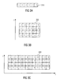
- Fig. 3a ⁇ 3c illustrate the binary values of a watermark signature that are to be encoded in different frequency bands.
- a watermark may be used to transmit information, in the following, we will focus on the aspect of using a watermark to transmit a watermark signature.
- a watermark signature may be an arbitrary sequence of bits, e.g. a bit sequence: [1, 1, -1, 1, -1, -1].
- Fig. 3a illustrates a corresponding watermark signature 310.
- the watermark bit sequence is spread in frequency by using a spreading sequence.
- a spreading vector comprising m values may be employed.
- a spreading vector only comprising Is e.g. [1, 1, 1] may be employed which results in that the watermark signature is copied for each respective frequency band.
- the spreading vector may also comprise -1s, e.g. [1, -1, 1], which results in that the watermark signature is inverted before being copied for being encoded in the respective frequency band for the respective -1 bits.
- Fig. 3b illustrates the above watermark signature that is frequency-spread by employing a spreading vector [1, -1, 1, -1] to obtain a frequency-spreaded watermark 320.
- the frequency-spreaded watermark may also be spread in a time-domain by employing a spreading vector.
- a spreading vector For example, by employing a vector [1, -1] for time spreading, each one of the frequency-spread watermark signatures may at first be encoded in its original form, and may then be inverted for being encoded.
- Fig. 3c illustrates the frequency-spreaded and time-spreaded watermark signature 330 wherein time spreading has been conducted by employing a spreading vector [1, -1].
- the watermark signature may be repeatedly encoded.
- the different bit sequences may be differentially encoded.
- a modulator 307 carries out the actual modulation, i.e., the generation of the watermark signal waveform depending on the binary information given at its input.
- N f parallel inputs, 401 to 40N f contain the bit streams for the different subbands.
- Each bit of each subband stream is processed by a bit shaping block (411 to 41N f ).
- the output of the bit shaping blocks are waveforms in time domain.
- the baseband functions can be different for each subband. If chosen identical, a more efficient implementation at the decoder is possible.
- the embedding process described above refers to an antipodal BPSK modulation scheme, i.e., where the encoded information bit simply changes the sign of the bit forming function.
- two or more bits can be grouped and a higher order modulation constellation (such as QAM or hl-PSK) can be used.
- Differential encoding can still be applied, as commonly done, for instance, in differentially-encoded QPSK.
- the bit shaping for each bit is repeated in an iterative process controlled by a psychoacoustical processing module 102. Iterations may be necessary to fine tune the weights ⁇ (i, j) to assign as much energy as possible to the watermarks while keeping it inaudible.
- the bit forming baseband function g i T t is normally non zero for a time interval much larger than T b , although the main energy is concentrated within the bit interval.
- T b 40 ms.
- T b 40 ms.
- the choice of T b as well as the shape of the function affect the system considerably. In fact, longer symbols provide narrower frequency responses. This is particularly beneficial in reverberant environments. In fact, in such scenarios the watermarked signal reaches the microphone via several propagation paths, each characterized by a different propagation time. The resulting channel exhibits strong frequency selectivity.
- ISI intersymbol interference
- the watermark signal is obtained by summing all outputs of the bit shaping filters ⁇ i s i t .
- Fig. 5 shows a block schematic diagram of a watermark inserter 500.
- the watermark signal 501b is generated in the processing block 501 (also designated as watermark generator) from binary data 501 a and on the basis of information 504, 505 exchanged with the psychoacoustical processing module 502.
- the information provided from block 502 typically guarantees that the watermark is inaudible.
- the watermark generated by the watermark generator 501 is added to the audio signal 506.
- weighting factors y(i, j) are needed to calculate the waveforms s i,j (t) for each subband.
- the purpose of the weighting factors y(i, j) is to hide the watermark inaudible in the resulting watermarked signal 507.
- the weighting factors y(i, j) are provided by the psychoacoustical processing module 502 which comprises 3 parts.
- the first part is an analysis module which transforms the time audio signal into the time/frequency domain. This analysis module may carry out parallel analyses in different time/frequency resolutions.
- the time/frequency data is transferred to the psychoacoustic model (PAM), in which masking thresholds for the watermark signal are calculated according to psychoacoustical considerations.
- PAM psychoacoustic model
- the masking thresholds indicate the amount of energy which can be hidden in the audio signal for each subband and time block.
- the last block in the psychoacoustical processing module 502 is the amplitude calculation module. This module determines the amplitude gains to be used in the generation of the watermark signal so that the masking thresholds are satisfied, i.e., the embedded energy is less or equal to the energy defined by the masking thresholds.
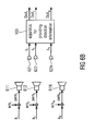
- a single loudspeaker 610 is used for the reproduction of a watermarked audio signal awm.
- the watermark signal wm is combined with an audio signal a by a combination unit 605 to obtain a watermarked audio signal awm.
- the watermark signal wm may have been created as described with reference to Figs. 3a - 4 .
- the watermarked signal awm may have been generated by a watermark generator as described with reference to Fig. 5 .
- the watermark signal wm may have been added to the audio signal ⁇ .
- the watermarked audio signal awm resulting from the combination conducted by the combining unit 605 is then reproduced by the loudspeaker 610 and recorded by sensors 621, 622, 62N, e.g, N microphones of a microphone array such that N signals s 1 , s 2 , ..., s N are obtained.
- the recorded signals s 1 , s 2 , ..., s N do not only comprise the watermarked loudspeaker signals, but also comprise interfering noise, e.g. talkers in a room and effects caused by reverberation.
- the recorded signals s 1 , s 2 , ..., s N are then inputted into an apparatus 100 for providing direction information according to an embodiment.
- the apparatus 100 determines and outputs direction information, e.g. it may determine and output a direction of arrival (DoA).
- DoA direction of arrival
- multiple loudspeakers 611, 612, ..., 61N may be adapted to output multiple watermarked signals awm 1 , awm 2 , ..., awm M .
- Different watermark signals wm 1 , wm 2 , ..., wm M are added to audio signals a 1 , a 2 , ..., a M , e.g. panned channels of an audio item used for home theater reproduction.
- the processing for the present scenario is similar to a situation where only one loudspeaker is reproducing a watermarked signal.
- Fig. 7 illustrates an apparatus 100 for providing direction information according to an embodiment.
- a plurality of received watermarked audio signals s 1 , s 2 , ..., s N for example signals, which may have been recorded by the microphones 621, 622, ..., 62N depicted in Fig. 6 , are illustrated.
- the received watermarked signals s 1 , s 2 , ..., s N which are represented in a time domain, are fed into analysis modules 711, 712, ..., 71N for being transformed into a time-frequency domain and for being normalized.
- one of the received watermarked audio signals is considered.
- One of the analysis modules transforms the watermarked audio signal from a time domain into the time-frequency domain by employing an analysis filter bank.
- the input of the filter bank is the respective watermarked audio signal.
- Its output are the complex coefficients b i AFB j for the i-th branch or subband at time instant j. These values contain information about the amplitude and the phase of the signal at center frequency f i and time j ⁇ Tb.
- the filter bank comprises N f branches, one for each spectral subband i. Each branch splits up into an upper subbranch for the in-phase component and a lower subbranch for the quadrature component of the subband i.
- b i AFB t r t ⁇ e - j ⁇ 2 ⁇ ⁇ ⁇ f i ⁇ t * g i R t
- * indicates convolution
- g i R t is the impulse response of the receiver lowpass filter of subband i.
- g i R t is equal to the baseband bit forming function g i T t of subband i in the modulator in order to fulfill the matched filter condition, but other impulse responses are possible as well.
- Fig. 8a gives an exemplary overview of the location of the coefficients on the time-frequency plane.
- the height and the width of the rectangles respectively indicate the bandwidth and the time interval of the part of the signal that is represented by the corresponding coefficient b i AFB j ⁇ k .
- the analysis filter bank can be efficiently implemented using the Fast Fourier Transform (FFT).
- FFT Fast Fourier Transform
- ECC equal gain combining
- n > 1 is a straightforward extension of the formula above.
- the normalization is carried out for each subband i and each time instant j.
- the normalization factor may be computed for one microphone only and then applied to all microphones, in case that the direction of arrival estimation uses also the amplitude of the receiver-specific information.
- Fig. 8b illustrates a subband signal, wherein two watermark signal portions WM1 and WM2 are time-multiplexed.
- the subband signal comprises the sound portion of a first audio source LS 1 from a first loudspeaker and the sound portion of a second sound source LS2 from a second loudspeaker.
- the subband signal also either comprises the watermark signal portion WM1 from a first loudspeaker or the watermark signal portion WM2 from a second loudspeaker.
- the time-frequency domain signals S 1 , S 2 , ..., S N are fed into a selection module 720.
- the selection module 720 determines which of the available signals S 1 , S 2 , ..., S N should be used to perform the subsequent synchronization.
- the selection module 720 is adapted to choose one of the input signals S 1 , S 2 , ..., S N randomly.
- the selection module might select the time-frequency domain signal S 1 .
- the selection module 720 is adapted to average the signals S 1 , S 2 , ..., S N and use the averaged signal.
- the selection module 720 then feeds the resulting signal into a differential decoder 730.
- a differential decoder 730 At the input of the differential decoder 730 we have amplitude normalized complex coefficients b i norm j which contain information about the phase of the signal components at frequency f i and time instant j. As the bits are differentially encoded at the transmitter, the inverse operation must be performed here.
- the differential decoder 730 differentially decodes the inputted signal to obtain so called soft bits by first calculating the difference in phase of two consecutive coefficients and then taking the real part of the phase. It should be noted that the resulting soft bits can take any real value and no hard decision on the bit is made yet. As the soft bits can take any real value, they do not necessarily have to be -1 or 1, but instead may have a real value different from -1 or 1, such as, for example, 0.92, -0.88, 0.97, and the like.
- the subband signal when inputted into the differential decoder, the subband signal might be oversampled.
- the differential decoder 730 then feeds the soft bit stream into an integration module 740, which integrates the soft bit stream in time across several synchronization signatures to further improve the accuracy of synchronization.
- Fig. 9a depicts a corresponding sequence, If the only employed (e.g. time-spreaded) watermark signature wm1 comprises N bits, then the bit sequence is repeated after N bits, and the only watermark signature then forms the synchronization block sync of length N bits.
- a system may comprise more than one loudspeaker.
- To obtain the estimate of the direction of arrival of each loudspeaker it is necessary to determine which part of the recorded signal was emitted by a certain loudspeaker. Therefore, the watermark signals have to be multiplexed.
- CDMA code division multiple access
- FDMA frequency divisional multiple access
- TDMA time division multiple access
- time division multiple access is employed.
- To determine which parts of the recorded signal belong to a certain loudspeaker different watermark signatures are embedded into different loudspeaker signals.
- Fig. 10 illustrates the time multiplexing for the use of two loudspeakers and synchronization signatures comprising six sequences.
- different loudspeakers may transmit different watermarks, e.g. two watermarks wm1 wm2, which may be time-multiplexed.
- N the number of bits of both (e.g. time-spreaded) watermarks.
- the first watermark signature wm1 is transmitted.
- the second watermark signature is transmitted.
- the first watermark signature wm1 is transmitted again, followed by the second watermark signature wm2 and so on.
- the synchronization block sync then comprises the watermarks wm1, wm2 and has 2 ⁇ N bits.
- Fig. 9b depicts the described scenario with two multiplexed watermark signatures.
- Each synchronization block is repeatedly transmitted. Assuming that the synchronization sequence has N sync bits, then bit 1 is equal to bit N sync + 1, and equal to bit 2 ⁇ N sync + 1, and so on. Bit 2 is equal to bit N sync + 2, and equal to bit 2 ⁇ N sync + 2, and so on.
- N os differentially decoded bit value candidates b ⁇ i (j, k) have been created for each single bit b ⁇ (j) of a considered subband i.
- the integration module is adapted to integrate the soft bits such that a plurality of soft bits of different synchronization blocks are added to improve robustness of the watermark decoding process.
- the bit stream comprising the differentially decoded bits is divided in subsequent periodical blocks p1, p2, p3 having N sync bits.
- the integration module 740 is not aware of where a synchronization block starts. However, this is not necessary, as the periodicity of the differentially decoded bit stream does not depend on the starting point of the synchronization block, but instead depends on the length of the synchronization block. For that, the first bit of a synchronization block may be located somewhere within a periodical block. Fig. 9c illustrates this scenario.
- corresponding bits of different periodical blocks are added. For example, the first bit of the first, second and third watermark period are added, the second bit of the first second and third watermark period are added, and so on up to the N sync bit of the first, second and third watermark period.
- i is the considered subband
- K represents the number of synchronization blocks that are averaged
- k represents the actual synchronization block that is considered
- j is the bit position considered within the periodical blocks.
- the averaged synchronization block has N sync bits: b i avg 0 , b i avg 1 , b i avg 2 , ... , b i avg ⁇ N sync - 1 .
- the first bit of the first watermark signature may be located somewhere in the averaged synchronization block p0.
- Fig. 9d illustrates the scenario showing an averaged synchronization block p0.
- integration is particularly important, since they often contain gaps with no watermark signal. By this, errors that are existent in the soft bit stream will normally be reduced when integration in time is conducted.
- the integration module 740 feeds the integrated soft bit stream into a synchronization module 750 which performs a robust synchronization.
- the synchronization module 750 performs a correlation with the embedded synchronization signature. Resulting from this is a synchronization hit position. Synchronization in the synchronization module 750 will now be explained in more detail.
- the task of the synchronization module 750 is to find the temporal alignment of the one or more watermarks within the averaged synchronization block.
- the problem of synchronizing the decoder to the encoded data is twofold.
- the analysis filter bank must be aligned with the encoded data, namely the bit shaping functions g i T t used in the synthesis in the modulator must be aligned with the filters g i R t uses for the analysis.
- This problem is illustrated in Figure 12a , where the analysis filters are identical to the synthesis ones. At the top, three bits are visible. For simplicity, the waveforms for all three bits are not scaled. The temporal offset between different bits is T b .
- the bottom part illustrates the synchronization issue at the decoder: the filter can be applied at different time instants, however, only curve 1299a is correct and allows to extract the first bit with the best signal to noise ratio SNR and signal to interference ratio SIR. In fact, an incorrect alignment would lead to a degradation of both SNR and SIR.
- bit synchronization Once the bit synchronization has been achieved, bits can be extracted optimally. However, it may also be necessary to know where a watermark signature starts. This issue is illustrated in Figure 12b and is referred to as message synchronization. In the stream of decoded bits only the starting position marked by a bold arrow 1299b is correct and allows to decode the k-th message.
- the watermark signature may also be referred to as synchronization signature.
- a synchronization signature may comprise a plurality of synchronization sequences.
- the synchronization sequence may only comprise a single bit.
- a synchronization signature comprises a plurality of bits.
- the synchronization signature is assumed to be composed of N s synchronization sequences in a predetermined order which are embedded continuously and periodically in the watermarked audio signal.
- the synchronization module 750 is capable of retrieving the temporal alignment of the synchronization sequences.
- the synchronization module can identify the beginning af each synchronization signature by finding the temporal alignment of the synchronization sequences. We refer to the temporal positions at which a new synchronization signature starts as synchronization hits.
- the processing blocks, of the synchronization module are depicted in Figures 11a and 11b ,
- the synchronization support unit carries out the bit synchronization and the message synchronization at once by analyzing the output of the synchronization signature correlator 1201.
- the data in time/frequency domain 204 is provided by the analysis module.
- the analysis module oversamples the data with factor N os .
- N os indicates the oversampling factor
- N t indicates a time-spreading factor
- N s indicates the number of synchronization sequences.
- the synchronization signature consists of 3 sequences (denoted with a, b, and c).
- the exact synchronization hits are denoted with arrows and correspond to the beginning of each synchronization signature.
- the synchronization block must contain (or typically contains) one synchronization hit as depicted in Figure 12d .
- Each of the bits of the averaged synchronization block is a candidate synchronization hit.
- Block 1201's task is to compute a likelihood measure for each of candidate bit of the synchronization block. This information is then passed to block 1204 which computes the synchronization hits.
- the synchronization signature correlator For each of the N sbl candidate synchronization positions the synchronization signature correlator computes a likelihood measure, the latter is larger the more probable it is that the temporal alignment (both bit and partial or full message synchronization) has been found.
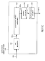
- the processing steps are depicted in Figure 11c .
- Block 1301 carries out the temporal despreading, i.e., multiplies every N t bits with the temporal spreading sequence C t and then sums them. This is carried out for each of the N f frequency subbands.
- Figure 13a shows an example.
- the candidate synchronization position is marked. From that bit, with N os offset, N t .
- N s are taken by block 1301 and time despread with sequence c t , so that Ns bits are left.
- bit 1302 the bits are multiplied element-wise with the N s spreading sequences (see Figure 13b ).
- the frequency despreading is carried out, namely, each bit is multiplied with the spreading sequence c f and then summed along frequency.
- block 1304 computes the likelihood measure by taking the absolute values of the N s values and sums.
- the output of block 1304 is in principle a non coherent correlator which looks for the synchronization signature.
- N s namely the partial message synchronization mode
- synchronization sequences e.g. a, b, c
- the correlator is not correctly aligned with the signature; its output will be very small, ideally zero.
- the full message synchronization mode it is advised to use as many orthogonal synchronization sequences as possible, and then create a signature by carefully choosing the order in which they are used. In this case, the same theory can be applied as when looking for spreading sequences with good auto correlation functions.
- the correlator is only slightly misaligned, then the output of the correlator will not be zero even in the ideal case, but anyway will be smaller compared to the perfect alignment, as the analysis filters cannot capture the signal energy optimally.
- This synchronization hits computation block analyzes the output of the synchronization signature correlator to decide where the synchronization positions are. Since the system is fairly robust against misalignments of up to T b /4 and the T b is normally taken around 40 ms, it is possible to integrate the output of 1201 over time to achieve a more stable synchronization. A possible implementation of this is given by an IIR filter applied along time with a exponentially decaying impulse response. Alternatively, a traditional FIR moving average filter can be applied. Once the averaging has been carried out, a second correlation along different N t N s is carried out ("different positional choice"). In fact, we want to exploit the information that the autocorrelation function of the synchronization function is known.
- the above-described concept to find a synchronization hit position of a synchronization signature is repeatedly applied for each watermark.
- a synchronization hit position within the averaged synchronization block is determined. Determination of the synchronization hit position of each watermark is repeatedly conducted as explained with reference to Fig. 11a - 13d for each one of the watermarks, wherein the watermark signature of the considered watermark is employed as synchronization signature
- the recorded signal is then divided into M segments, each segment M belonging to a certain watermark of a certain loudspeaker.
- the estimation of the direction of arrival is then carried out for each segment.
- the direction estimator 760 will have M outputs, each representing the direction of arrival of sound emitted by a certain loudspeaker.
- the synchronization module 750 provides the one or more synchronization hit position within the averaged synchronization block and delivers the synchronization hit position to a direction estimator 760.
- the synchronization hits are calculated if the watermarks is embedded continuously and only one loudspeaker is used. If this is not the case, the synchronization has to be preformed to find the starting point for the direction estimation.
- the analysis modules 711, 712, ..., 71N not only provide the time-frequency domain signals S 1 , S 2 , ..., S N to the selection module 720, but also provide the signals S 1 , S 2 , ..., S N to integration modules 741, 742, ..., 74N.
- What is delivered to the integration modules 741, 742, ..., 74N are in fact the (oversampled) normalized complex coefficients b i norm j ⁇ q which are the same coefficients as provided to the selection module 720.
- the stream comprising the oversampled normalized complex coefficients is divided in subsequent periodical blocks p11, p12, p13.
- the complex coefficient stream is divided in exactly the same way in blocks as the differentially decoded bit stream has been separated into periodical blocks p1, p2, p3. Bits and samples with corresponding time indexes and (oversampling positions) are comprised in corresponding periodical blocks.
- a signal s1 may be provided to the analysis module 711.
- the analysis module 711 generates a time-frequency domain signal S 1 comprising a plurality of subband signals, each one of the subband signals being represented as a stream of complex coefficients.
- the selection module 720 may select S1 such that the subsequent synchronization is performed based on the time-frequency domain signal S1.
- a particular subband of the time-frequency domain signal S1 is considered.
- This subband may comprise complex coefficients c(i,j), wherein i denotes the subband and j denotes the time index. For example, consider the complex coefficients c(i, 1), c(i, 2), c(i, 3), c(i, 4), c(i, 5) and c(i, 6) of this subband.
- Differential decoding based on these values by a differential decoder provides six soft bits, namely d(i, 1) based on c(i, 1) and the preceding subband sample; d(i, 2) based on c(i, 2) and the preceding c(i, 1); d(i, 3) based on c(i, 3) and the preceding c(i, 2); d(i, 4) based on c(i, 4) and the preceding c(i, 3); d(i, 5), based on c(i, 5) and the preceding c(i, 4); and d(i, 6) based on c(i, 6) and the preceding c(i, 5).
- d(i, j) i represents the subband and j represents the time index.
- the complex coefficients of the frequency band i are also fed into the integration module 741 of Fig. 7 . If integration module 740 now divides the differentially decoded bit stream comprising the soft bits d(i, 1), d(i, 2), d(i, 3), d(i, 4), d(i, 5), d(i, 6) into a first periodical block p1 comprising d(i, 1), d(i, 2) and d(i, 3) and into a second periodical block p2 comprising d(i, 4), d(i, 5) and d(i, 6) then the complex coefficients c(i, 1), c(i, 2), c(i, 3), c(i, 4), c(i, 5) and c(i, 6) are also divided into two blocks, namely a first block compising the complex coefficients c(i, 1), c(i, 2) and c(i, 3) and into a second block comprising the
- the oversampled soft bits b(i, j, q) are divided into a first and a second periodical block p1 and p2, then the complex coefficients c(i, j, q) are also divided into two blocks p11 and p12. (Here, i indicates the subband, j indicates the time index and q indicates the oversampling position.) If the first periodical block p1 comprises soft bit b(i, j, q), then the first block p11 comprises complex coefficient c(i, j, q) with the same indexes j, q. If the second periodical block p2 comprises soft bit b(i, j, q), then the second block p12 also comprises the complex coefficient c(i, j, q) with the same indexes j, q.
- each one of the periodical blocks p11 p12, p13 generated by the integration modules 741, 742, ..., 74N corresponds to the length of the periodical blocks p1, p2, p3 generated by the integration module 740.
- corresponding complex coefficients are averaged. For example, corresponding complex coefficients of different periodical blocks are added. For example, the first complex coefficient of the first, second and third synchronization period are added, the second complex coefficient of the first second and third watermark period are added, and so on.
- K represents the number of periodical blocks of a considered subband i that are averaged
- k represents the actual periodical block that is considered
- j is the position of the complex coefficient within the periodical blocks.
- An averaged periodical block is determined for each frequency band and each signal.
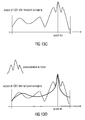
- Figs. 15a and 15b illustrate how the integration helps in acquiring the wanted phase information of the watermark signal.
- a mn represents the audio part emitted by loudspeaker m and received at microphone n.
- the recorded signal comprises the superposition of all emitted audio signals together with only one watermark signal.
- K represents the number of synchronization blocks to be integrated.
- N synch represents the number of time slots for one complete synchronization block.
- N synch M ⁇ N seq , where M is the number of loudspeakers and N seq is the number of sequences of one synchronization signature.
- M the number of loudspeakers
- N seq the number of sequences of one synchronization signature.
- Fig. 15b the situation is illustrated after the integration was performed.
- Phase modulation as employed in the context of this embodiment is based on some fundamental ideas: Assuming that each sampled complex coefficient corresponds to an encoded bit position, the phase value of the actual sample is compared with the phase value of the previous sample. Consider for example binary phase shift keying (BPSK). If the phase values of both samples are identical, this corresponds to a first encoded bit value, e.g. the encoded bit value is 1. However, if both phase values differ e.g. by 180° (or ⁇ ⁇ ), this corresponds to a second encoded bit value, e.g. the encoded bit value is -1.
- BPSK binary phase shift keying
- phase modulation employing, for example, binary phase shift keying it is essential that samples of subsequent bit positions either have the same phase value or a phase value that differs by 180° ( ⁇ ⁇ ). Therefore, when encoding phase modulated values, a modulation is employed, such that the phase values of samples corresponding to subsequent bit positions are either equal or differ by 180° depending on the encoded bit value.
- a loudspeaker transmits a bit sequence encoded by phase modulation.
- All audio receivers e.g. microphones, receive the phase modulated bit sequence.
- the phase difference of samples corresponding to subsequent bit positions of the received audio signals S 1 , S 2 , ..., S N should be (nearly) the same for all signals of the different microphones. If two microphones receive the same portion of the audio signal at the same time, the absolute phase values should also be identical. However, as the microphones are spaced apart (although they may only slightly be spaced apart), a first microphone may receive the same portion of the audio signal slightly earlier than a second microphone, e.g.
- a phase difference of two watermarked signals received by two microphones comprises information about the position of the loudspeaker that emitted the watermarked signal relative to the location of the two microphones.
- the integration modules 741, 742, ..., 74N feeds the averaged periodical blocks determined for each frequency band and each signal into the direction estimator 760 which has already received the synchronization hit position.
- the direction estimator 760 then performs the estimation of the direction of arrival upon the part of the incoming data pointed to by the synchronization hit position for each averaged periodical block.
- the direction estimator performs sample integration based on the averaged periodical blocks. Only the oversampling position is considered for each bit that is indicated as the correct oversampling position by the synchronization hit position. All other oversampling positions are discarded and not considered in the sample integration.
- the watermark signature is considered bit by bit starting with the first bit of the first watermark signature.
- the position of the corresponding sample value in the averaged periodical block is indicated by the synchronization hit position. All bits of the watermark signature and their corresponding sample values are considered.
- a bit value of 1 is indicated by equal phase values of the actual and the previous sample, while a bit value of -1 is indicated by a phase difference of 180° of the actual and the previous sample. This is illustrated in Fig. 15c .
- the sequence of sample values of complex coefficients is 1510 depicted.
- Bit sequence 1515 indicates the encoded bits assuming that differential encoding is employed.
- the synchronization module now generates a processed sequence of averaged complex coefficients 1520, such that all complex coefficients roughly have the same phase value by either leaving the complex coefficient unchanged or by changing its phase value by 180°.
- the decision, whether a phase value of a complex coefficient is changed by 180° is determined based on evaluating the encoded bit sequence of the watermark.
- an apparatus may calculate whether a bit value has been encoded by using a complex coefficient with a desired first phase value or whether a bit value has been encoded by using a complex coefficient with an undesired second phase value. If the corresponding sample value has been determined to have an undesired second phase value, the phase value of this complex coefficient is changed by 180°.
- the absolute phase values of the complex coefficients for a certain frequency band of the processed sequence of averaged complex coefficients are now nearly the same for all complex coefficients regarding a certain frequency domain signal of a certain microphone.
- the synchronization module 750 After adjusting the phase of samples, all complex coefficients have phase values with roughly the same value.
- the synchronization module 750 now conducts integration on a sample-by-sample basis. All remaining sample values (the sampling values with the correct oversampling position) which relate to a considered watermark signature are integrated, i.e. averaged, for example, added and divided by the number of added samples to obtain an averaged complex coefficient 1530.
- Two effects are obtained: As a first effect a more stable absolute phase value is obtained.
- the different samples may be exposed to fluctuations within the channel such that the different phase values have roughly the same absolute phase values but not exactly the same phase values.
- As a second effect the effect of the audio signal within the averaged sample is minimized while the effect of the watermark signature is emphasized.
- an (absolute) phase value for each one of the averaged complex coefficients for the different microphones 611, 612, ..., 61N and for each frequency band i can be determined.
- the phase value is an averaged phase value.
- the absolute phase value of a complex coefficient may be determined by determining the phase value (the argument) of a complex coefficient.
- various types of direction information may be determined based on alternative determination concepts.
- Directional Audio Coding DirAC
- ESPRIT Estimation of Signal Parameters via Rotational Invariance Techniques
- B-format microphone signals which comprise an omnidirectional signal w(t) and three dipole signals x(t), y(t), z(t), which correspond to the x-, y-, and z-axis of a Cartesian coordinate system.
- Fig. 16 illustrates a microphone arrangement of six microphones such that they form three microphone pairs.
- the first microphone pair mx1, mx2 is assumed to be located on an x-axis of a Cartesian coordinate system.
- the second microphone pair my1, my2 is arranged such that it can be assumed that it is located on a y-axis of the Cartesian coordinate system.
- the third microphone pair mz1, mz2 is arranged such that it can be assumed that it is located on a z-axis of the Cartesian coordinate system.
- an azimuth angle may be calculated based on the calculated phase values.
- ⁇ x - 2 ⁇ ⁇ / ⁇ ⁇ d ⁇ sin ⁇
- ⁇ y - 2 ⁇ ⁇ / ⁇ ⁇ d ⁇ sin ⁇
- an angle ⁇ specifying a direction of arrival of a sound wave comprising a watermark signature can be determined with respect to the xy-plane and a certain frequency band i.
- Determination of the angle ⁇ might be repeated for each one of a plurality of different frequency bands i. For each frequency band, an angle ⁇ is obtained that should be nearly the same for each frequency band. However, disturbances regarding certain frequency bands may influence the correctness of the determined value of angle ⁇ which is determined based on these frequency bands.
- an average value of the determined values for the angle ⁇ is calculated. For example, the calculated angle values may be added and divided by the number of added to obtain the value of angle ⁇ as an average value.
- the distance dx between the microphone mx1 and mx2 the distance dy between the microphone my1 and my2 and the distance dz between the microphone mz1 and mz2 are equal.
- the distance dx between the microphone mx1 and mx2, the distance dy between the microphone my1 and my2 and the distance dz between the microphone mz1 and mz2 are not equal.
- the modified phase differences have to be adjusted to take the different distances into account, e.g. by applying a correction factor.
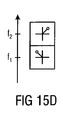
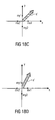
- the direction of arrival vector is explained with reference to Fig.18a - 18d .
- the situation in a two-dimensional xy-plane is explained. It is assumed that the distance dx between the microphone mx1 and mx2 and the distance dy between the microphones my1 and my2 are equal. However, the explanations given also apply to the three-dimensional case and to situations where the microphone distances are not equal, but where the phase differences ⁇ vx and ⁇ vy have been adjusted, e.g. by applying a distance factor.
- the x-component of the vector ⁇ vx is 0, i.e. no phase difference exists with respect to the absolute phase values of the signals received by both microphones mx1 and mx2.
- the corresponding audio wave is hitting both microphones mx1 and mx2 at the same time, and it is assumed that the sound source is equally spaced apart from both microphones mx1 and mx2.
- the direction of arrival vector a' is neither negative nor positive.
- the y-component of the vector ⁇ vy is 0, i.e. no phase difference exists regarding the absolute phase values of the signals received by both microphones my1 and my2.
- the corresponding audio wave is hitting both microphones my1 and my2 at the same time, and it is assumed that the sound source is equally spaced apart from both microphones my1 and my2.
- the direction of arrival vector a' is neither negative nor positive.
- the x-component of the vector ⁇ vx is -1. As ⁇ vx vx1 - vx2 this indicates that the absolute phase value vx2 is greater than the absolute phase value vx1, and thus that the respective audio wave arrived earlier at microphone mx2 than at microphone mx1. Thus the direction of arrival vector a' points to the negative direction of the y-axis.
- phase differences ⁇ vx and ⁇ vy are equal, and as it can be assumed that a corresponding audio wave propagates equally fast in x-direction as in y-direction, the x-component and the y-component of the direction of arrival vector have equal values.
- phase differences ⁇ vx and ⁇ vy are equal and as we can assume that a corresponding audio wave propagates faster, in x-direction than in y-direction and that its velocity in x-direction is two times of the velocity in y-direction, the x-component is twice the size of the y-component of the direction of arrival vector.
- an average direction of arrival vector may be determined.
- Averaging may, for example, be achieved by adding the plurality of direction of arrival vectors and by dividing the components of the obtained vector by the number of normalized direction of arrival vectors that are averaged.
- azimuth and elevation angles may be calculated based on the determined direction of arrival vector using the methods employed in the context of Directional Audio Coding (DirAC).
- ⁇ px denote the difference between the complex values obtained from microphones mx1 and mx2 from Figure 16 .
- ⁇ py and ⁇ pz are obtained for the y and z axes.
- p0 be the average of the complex values obtained at all microphones.
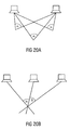
- Fig. 19 illustrates position estimation in a two-dimensional scenario. There, we assume, that the position of the loudspeakers is known. We further assume that the loudspeakers and the array of recording microphones are located in the same plane.
- a direction of arrival vector is determined for each one of the loudspeakers according to one of the above-described embodiments.
- the direction of arrival vector of the first loudspeaker points to the first loudspeaker.
- the direction of arrival vector of the second loudspeaker points to the second loudspeaker.
- a direction of arrival vector points to the direction of arrival of a sound wave from a loudspeaker, wherein the components of the vector may be expressed with reference to a Cartesian coordinate system, In embodiments, however, the axes of the coordinate system are defined by the location of the microphones: The location of mx1 and mx2 defines the x-axis, and the location of my1 and my2 defines the y-axis of the coordinate system the direction of arrival vector refers to.
- an apparatus for position estimation is adapted to calculate a direction of arrival vector for each loudspeaker outputting sound waves comprising watermark signatures.
- a first line in the two-dimensional plane is calculated that is parallel to the direction of arrival vector of the first loudspeaker and that intersects the position of the first loudspeaker.
- a second line in the two-dimensional plane is calculated that is parallel to the direction of arrival vector of the second loudspeaker and that intersects the position of the second loudspeaker. Then, the intersection point of the first and second line in the two dimensional plane is calculated, wherein the intersection point determines the position of the microphone array.
- the described concept is applied in environments, wherein microphone array and the loudspeakers are not located in a two dimensional plane, applying three-dimensional direction of arrival vectors (direction of arrival vectors with three components). There, it is assumed that the location of the loudspeakers is known.
- An apparatus calculates the lines parallel to the determined direction of arrival vectors, wherein the calculated lines intersect the loudspeaker position of the loudspeaker of their direction of arrival vector. The point, where all calculated lines intersect each other is the determined position of the microphone array.
- a third loudspeaker outputting a third audio wave comprising a watermark signature
- the ambiguity could be resolved. This is explained with reference to Fig. 20b .
- the directions of arrival of at least three loudspeakers M ⁇ 3
- the spatial position of the microphone array can also be determined.
- Fig. 21 illustrates a corresponding position estimator.
- the loudspeakers and the recording unit are in a common plane.
- the spatial positions the loudspeakers have to be known at the receiver. Relying on this information, it is possible to obtain the recording position by solving a system of nonlinear equations in the position estimator 800.
- an apparatus for position estimation calculates the first direction of arrival vector of the first loudspeaker, the second direction of arrival vector of the second loudspeaker and the third direction of arrival vector of the third loudspeaker. Then, a first angle ⁇ between the first and second direction of arrival vector and a second angle ⁇ between the second and third direction of arrival vector may be calculated. The apparatus for decision estimation then determines the point in the two-dimensional plane such that three lines each of which intersecting a loudspeaker position and the determined point have the determined angle relations with respect to each other. I.e.
- the first line intersecting the first loudspeaker position and the second line intersecting the second loudspeaker position intersect each other in the determined point such that their intersection angle is equal to the first angle.
- the second line intersecting the second loudspeaker position and the third line intersecting the third loudspeaker position intersect each other in the determined point such that their intersection angle is equal to the second angle.
- the determined point is the position of the microphone array.
- a position estimator determines the position of a microphone array whose orientation is not known for the three-diemnsional case, i.e. for a configuration where the loudspeakers and the microphone array are not all located in a two-dimensional plane. Determination is achieved based on the above-described concept by employing three-dimensional direction of arrival vectors, i.e. direction of arrival vectors having three components.
- Fig. 22 illustrates an apparatus for spatial position estimating according to an embodiment.
- the apparatus for spatial position estimating comprises an apparatus 100 for providing direction information according to one of the above-described embodiments, which which processes received watermarked audio signals rx1 rx2.
- the apparatus for spatial position estimating comprises a position estimator 300 for estimating a position of the apparatus for spatial position estimating.
- the position estimator is adapted to estimate the position of the apparatus for spatial position estimating based on the direction information provided by the apparatus for providing direction information.
- aspects have been described in the context of an apparatus, it is clear that these aspects also represent a description of the corresponding method, where a block or device corresponds to a method step or a feature of a method step. Analogously, aspects described in the context of a method step also represent a description of a corresponding block or item or feature of a corresponding apparatus.
- the inventive decomposed signal can be stored on a digital storage medium or can be transmitted on a transmission medium such as a wireless transmission medium or a wired transmission medium such as the Internet.
- embodiments of the invention can be implemented in hardware or in software.
- the implementation can be performed using a digital storage medium, for example a floppy disk, a DVD, a CD, a ROM, a PROM, an EPROM, an EEPROM or a FLASH memory, having electronically readable control signals stored thereon, which cooperate (or are capable of cooperating) with a programmable computer system such that the respective method is performed.
- a digital storage medium for example a floppy disk, a DVD, a CD, a ROM, a PROM, an EPROM, an EEPROM or a FLASH memory, having electronically readable control signals stored thereon, which cooperate (or are capable of cooperating) with a programmable computer system such that the respective method is performed.
- Some embodiments according to the invention comprise a non-transitory data carrier having electronically readable control signals, which are capable of cooperating with a programmable computer system, such that one of the methods described herein is performed.
- embodiments of the present invention can be implemented as a computer program product with a program code, the program code being operative for performing one of the methods when the computer program product runs on a computer.
- the program code may for example be stored on a machine readable carrier.
- inventions comprise the computer program for performing one of the methods described herein, stored on a machine readable carrier.
- an embodiment of the inventive method is, therefore, a computer program having a program code for performing one of the methods described herein, when the computer program runs on a computer.
- a further embodiment of the inventive methods is, therefore, a data carrier (or a digital storage medium, or a computer-readable medium) comprising, recorded thereon, the computer program for performing one of the methods described herein.
- a further embodiment of the inventive method is, therefore, a data stream or a sequence of signals representing the computer program for performing one of the methods described herein.
- the data stream or the sequence of signals may for example be configured to be transferred via a data communication connection, for example via the Internet.
- a further embodiment comprises a processing means, for example a computer, or a programmable logic device, configured to or adapted to perform one of the methods described herein.
- a processing means for example a computer, or a programmable logic device, configured to or adapted to perform one of the methods described herein.
- a further embodiment comprises a computer having installed thereon the computer program for performing one of the methods described herein.
- a programmable logic device for example a field programmable gate array
- a field programmable gate array may cooperate with a microprocessor in order to perform one of the methods described herein.
- the methods are preferably performed by any hardware apparatus.
Landscapes
- Engineering & Computer Science (AREA)
- Physics & Mathematics (AREA)
- Health & Medical Sciences (AREA)
- Signal Processing (AREA)
- Acoustics & Sound (AREA)
- Multimedia (AREA)
- Human Computer Interaction (AREA)
- Audiology, Speech & Language Pathology (AREA)
- Computational Linguistics (AREA)
- General Physics & Mathematics (AREA)
- Radar, Positioning & Navigation (AREA)
- Remote Sensing (AREA)
- Otolaryngology (AREA)
- Circuit For Audible Band Transducer (AREA)
- Measurement Of Velocity Or Position Using Acoustic Or Ultrasonic Waves (AREA)
- Editing Of Facsimile Originals (AREA)
- Signal Processing For Digital Recording And Reproducing (AREA)
Priority Applications (16)
| Application Number | Priority Date | Filing Date | Title |
|---|---|---|---|
| EP11179591A EP2565667A1 (de) | 2011-08-31 | 2011-08-31 | Ankunftsrichtungsschätzung mittels mit einem Wasserzeichen versehenen Audiosignalen und Mikrofonanordnungen |
| RU2014111824/28A RU2575535C2 (ru) | 2011-08-31 | 2012-08-31 | Оценка направления прихода сигнала с использованием аудиосигналов с водяными знаками и массива микрофонов |
| EP12756427.6A EP2751587B1 (de) | 2011-08-31 | 2012-08-31 | Schätzung der ankunftsrichtung anhand von wasserzeichenmarkierten audiosignalen und mikrofonanordnungen |
| KR1020147008157A KR101719194B1 (ko) | 2011-08-31 | 2012-08-31 | 마이크로폰 배치들 및 워터마킹된 오디오 신호들을 이용한 도착 방향 추정 |
| HK14112131.9A HK1198718B (en) | 2011-08-31 | 2012-08-31 | Direction of arrival estimation using watermarked audio signals and microphone arrays |
| JP2014527673A JP5941545B2 (ja) | 2011-08-31 | 2012-08-31 | 透かしを入れたオーディオ信号およびマイクロホンアレイを用いる到来方向推定 |
| TW101131841A TWI480858B (zh) | 2011-08-31 | 2012-08-31 | 用以提供方向資訊之裝置及方法、用於空間位置估計之裝置及方法、和電腦程式 |
| AU2012300806A AU2012300806B2 (en) | 2011-08-31 | 2012-08-31 | Direction of arrival estimation using watermarked audio signals and microphone arrays |
| BR112014004778-2A BR112014004778B1 (pt) | 2011-08-31 | 2012-08-31 | Direção da estimativa de chegada utilizando sinais de áudio com marca d`água e matrizes de microfone |
| PCT/EP2012/066964 WO2013030339A1 (en) | 2011-08-31 | 2012-08-31 | Direction of arrival estimation using watermarked audio signals and microphone arrays |
| ES12756427.6T ES2558167T3 (es) | 2011-08-31 | 2012-08-31 | Estimación de dirección de llegada usando señales de audio con marca de agua y disposiciones ordenadas de micrófono |
| ARP120103237A AR087763A1 (es) | 2011-08-31 | 2012-08-31 | Aparato y metodo de la direccion de arribo usando señales de audio con marca de agua y arreglos de microfono |
| CN201280052151.0A CN103917886B (zh) | 2011-08-31 | 2012-08-31 | 使用附水印音频信号和麦克风阵列的到达方向估计 |
| MX2014002428A MX2014002428A (es) | 2011-08-31 | 2012-08-31 | Estimacion de direccion de arribo usando señales de audio con marca de agua y arreglos de microfono. |
| CA2846080A CA2846080C (en) | 2011-08-31 | 2012-08-31 | Direction of arrival estimation using watermarked audio signals and microphone arrays |
| US14/189,058 US11176952B2 (en) | 2011-08-31 | 2014-02-25 | Direction of arrival estimation using watermarked audio signals and microphone arrays |
Applications Claiming Priority (1)
| Application Number | Priority Date | Filing Date | Title |
|---|---|---|---|
| EP11179591A EP2565667A1 (de) | 2011-08-31 | 2011-08-31 | Ankunftsrichtungsschätzung mittels mit einem Wasserzeichen versehenen Audiosignalen und Mikrofonanordnungen |
Publications (1)
| Publication Number | Publication Date |
|---|---|
| EP2565667A1 true EP2565667A1 (de) | 2013-03-06 |
Family
ID=46826474
Family Applications (2)
| Application Number | Title | Priority Date | Filing Date |
|---|---|---|---|
| EP11179591A Withdrawn EP2565667A1 (de) | 2011-08-31 | 2011-08-31 | Ankunftsrichtungsschätzung mittels mit einem Wasserzeichen versehenen Audiosignalen und Mikrofonanordnungen |
| EP12756427.6A Active EP2751587B1 (de) | 2011-08-31 | 2012-08-31 | Schätzung der ankunftsrichtung anhand von wasserzeichenmarkierten audiosignalen und mikrofonanordnungen |
Family Applications After (1)
| Application Number | Title | Priority Date | Filing Date |
|---|---|---|---|
| EP12756427.6A Active EP2751587B1 (de) | 2011-08-31 | 2012-08-31 | Schätzung der ankunftsrichtung anhand von wasserzeichenmarkierten audiosignalen und mikrofonanordnungen |
Country Status (13)
| Country | Link |
|---|---|
| US (1) | US11176952B2 (de) |
| EP (2) | EP2565667A1 (de) |
| JP (1) | JP5941545B2 (de) |
| KR (1) | KR101719194B1 (de) |
| CN (1) | CN103917886B (de) |
| AR (1) | AR087763A1 (de) |
| AU (1) | AU2012300806B2 (de) |
| BR (1) | BR112014004778B1 (de) |
| CA (1) | CA2846080C (de) |
| ES (1) | ES2558167T3 (de) |
| MX (1) | MX2014002428A (de) |
| TW (1) | TWI480858B (de) |
| WO (1) | WO2013030339A1 (de) |
Cited By (5)
| Publication number | Priority date | Publication date | Assignee | Title |
|---|---|---|---|---|
| CN103308889A (zh) * | 2013-05-13 | 2013-09-18 | 辽宁工业大学 | 复杂环境下被动声源二维doa估计方法 |
| EP2899997A1 (de) * | 2014-01-22 | 2015-07-29 | Thomson Licensing | Tonsystemkalibrierung |
| CN110133595A (zh) * | 2018-02-09 | 2019-08-16 | 北京搜狗科技发展有限公司 | 一种声源测向方法、装置和用于声源测向的装置 |
| EP3642643A4 (de) * | 2017-06-23 | 2021-03-17 | Nokia Technologies Oy | Schallquellendistanzschätzung |
| WO2021116160A1 (en) * | 2019-12-10 | 2021-06-17 | Foccaert Y. Bvba | Location determination system, method for determining a location and device for determining its location |
Families Citing this family (39)
| Publication number | Priority date | Publication date | Assignee | Title |
|---|---|---|---|---|
| US10136239B1 (en) | 2012-09-26 | 2018-11-20 | Foundation For Research And Technology—Hellas (F.O.R.T.H.) | Capturing and reproducing spatial sound apparatuses, methods, and systems |
| US10175335B1 (en) | 2012-09-26 | 2019-01-08 | Foundation For Research And Technology-Hellas (Forth) | Direction of arrival (DOA) estimation apparatuses, methods, and systems |
| US20160210957A1 (en) | 2015-01-16 | 2016-07-21 | Foundation For Research And Technology - Hellas (Forth) | Foreground Signal Suppression Apparatuses, Methods, and Systems |
| US10149048B1 (en) | 2012-09-26 | 2018-12-04 | Foundation for Research and Technology—Hellas (F.O.R.T.H.) Institute of Computer Science (I.C.S.) | Direction of arrival estimation and sound source enhancement in the presence of a reflective surface apparatuses, methods, and systems |
| US9955277B1 (en) | 2012-09-26 | 2018-04-24 | Foundation For Research And Technology-Hellas (F.O.R.T.H.) Institute Of Computer Science (I.C.S.) | Spatial sound characterization apparatuses, methods and systems |
| US9549253B2 (en) * | 2012-09-26 | 2017-01-17 | Foundation for Research and Technology—Hellas (FORTH) Institute of Computer Science (ICS) | Sound source localization and isolation apparatuses, methods and systems |
| US9554203B1 (en) | 2012-09-26 | 2017-01-24 | Foundation for Research and Technolgy—Hellas (FORTH) Institute of Computer Science (ICS) | Sound source characterization apparatuses, methods and systems |
| US9679053B2 (en) | 2013-05-20 | 2017-06-13 | The Nielsen Company (Us), Llc | Detecting media watermarks in magnetic field data |
| EP2930923A1 (de) * | 2014-04-07 | 2015-10-14 | Thomson Licensing | Verfahren und Gerät zum Reagieren auf Wasserzeichen in digitalem Inhalt |
| US10410643B2 (en) | 2014-07-15 | 2019-09-10 | The Nielson Company (Us), Llc | Audio watermarking for people monitoring |
| US9482592B2 (en) * | 2014-09-24 | 2016-11-01 | General Monitors, Inc. | Directional ultrasonic gas leak detector |
| EP3073488A1 (de) * | 2015-03-24 | 2016-09-28 | Thomson Licensing | Verfahren und vorrichtung zur einbettung und rückgewinnung von wasserzeichen in einer ambisonics-darstellung eines schallfeldes |
| US20160294484A1 (en) * | 2015-03-31 | 2016-10-06 | Qualcomm Technologies International, Ltd. | Embedding codes in an audio signal |
| US10602265B2 (en) | 2015-05-04 | 2020-03-24 | Rensselaer Polytechnic Institute | Coprime microphone array system |
| US10425835B2 (en) * | 2015-12-04 | 2019-09-24 | Industrial Technology Research Institute | Post network entry connection method in millimeter wave communication system and related apparatuses using the same |
| US10394518B2 (en) * | 2016-03-10 | 2019-08-27 | Mediatek Inc. | Audio synchronization method and associated electronic device |
| US11080591B2 (en) | 2016-09-06 | 2021-08-03 | Deepmind Technologies Limited | Processing sequences using convolutional neural networks |
| KR102353284B1 (ko) | 2016-09-06 | 2022-01-19 | 딥마인드 테크놀로지스 리미티드 | 신경망을 사용하여 오디오 생성 |
| US10419511B1 (en) * | 2016-10-04 | 2019-09-17 | Zoom Video Communications, Inc. | Unique watermark generation and detection during a conference |
| KR102359216B1 (ko) * | 2016-10-26 | 2022-02-07 | 딥마인드 테크놀로지스 리미티드 | 신경망을 이용한 텍스트 시퀀스 처리 |
| CN110603863B (zh) * | 2017-05-02 | 2023-03-21 | 株式会社Ntt都科摩 | 终端、基站装置和通信方法 |
| CN108702558B (zh) * | 2018-03-22 | 2020-04-17 | 歌尔股份有限公司 | 用于估计到达方向的方法和装置及电子设备 |
| CN108713323B (zh) * | 2018-05-30 | 2019-11-15 | 歌尔股份有限公司 | 估计到达方向的方法和装置 |
| WO2020037555A1 (zh) * | 2018-08-22 | 2020-02-27 | 深圳市汇顶科技股份有限公司 | 评估麦克风阵列一致性的方法、设备、装置和系统 |
| US10708612B1 (en) * | 2018-12-21 | 2020-07-07 | The Nielsen Company (Us), Llc | Apparatus and methods for watermarking using starting phase modulation |
| US10652654B1 (en) * | 2019-04-04 | 2020-05-12 | Microsoft Technology Licensing, Llc | Dynamic device speaker tuning for echo control |
| CN114208209B (zh) | 2019-07-30 | 2023-10-31 | 杜比实验室特许公司 | 音频处理系统、方法和介质 |
| CN117499852A (zh) | 2019-07-30 | 2024-02-02 | 杜比实验室特许公司 | 管理在多个扬声器上回放多个音频流 |
| EP4005247A1 (de) | 2019-07-30 | 2022-06-01 | Dolby Laboratories Licensing Corporation | Koordination von audiovorrichtungen |
| US11968268B2 (en) | 2019-07-30 | 2024-04-23 | Dolby Laboratories Licensing Corporation | Coordination of audio devices |
| CN114846821B (zh) | 2019-12-18 | 2025-01-28 | 杜比实验室特许公司 | 音频设备自动定位 |
| CN113223544B (zh) * | 2020-01-21 | 2024-04-02 | 珠海市煊扬科技有限公司 | 音频的方向定位侦测装置及方法以及音频处理系统 |
| CN111343620A (zh) * | 2020-02-28 | 2020-06-26 | 捷开通讯(深圳)有限公司 | 多设备音频播放校正方法,装置及其终端 |
| CN113009411A (zh) * | 2021-02-25 | 2021-06-22 | 浙江德清知路导航研究院有限公司 | 一种具有定位功能的音频编解码芯片、定位方法及应用 |
| WO2022260031A1 (ja) * | 2021-06-09 | 2022-12-15 | ローム株式会社 | 音波処理装置、および超音波システム |
| TWI790694B (zh) * | 2021-07-27 | 2023-01-21 | 宏碁股份有限公司 | 聲音浮水印的處理方法及聲音浮水印產生裝置 |
| TWI806299B (zh) | 2021-12-21 | 2023-06-21 | 宏碁股份有限公司 | 聲音浮水印的處理方法及聲音浮水印產生裝置 |
| CN116486823B (zh) * | 2022-01-14 | 2025-09-05 | 宏碁股份有限公司 | 声音水印的处理方法及声音水印产生装置 |
| US12361954B2 (en) | 2023-06-01 | 2025-07-15 | Cisco Technology, Inc. | Ambience-adapted audio watermarking for teleconferencing |
Citations (1)
| Publication number | Priority date | Publication date | Assignee | Title |
|---|---|---|---|---|
| US20080247274A1 (en) * | 2007-04-06 | 2008-10-09 | Microsoft Corporation | Sensor array post-filter for tracking spatial distributions of signals and noise |
Family Cites Families (63)
| Publication number | Priority date | Publication date | Assignee | Title |
|---|---|---|---|---|
| US6632928B1 (en) | 1997-03-05 | 2003-10-14 | The United States Of America As Represented By The Department Of Health And Human Services | Immunotoxins and methods of inducing immune tolerance |
| GB9720054D0 (en) | 1997-09-19 | 1997-11-19 | Celltech Therapeutics Ltd | Biological products |
| AUPO930697A0 (en) | 1997-09-19 | 1997-10-09 | Walter And Eliza Hall Institute Of Medical Research, The | Catalytic antibodies and a method of producing same |
| WO1999063443A1 (en) * | 1998-06-01 | 1999-12-09 | Datamark Technologies Pte Ltd. | Methods for embedding image, audio and video watermarks in digital data |
| JP4026933B2 (ja) * | 1998-06-24 | 2007-12-26 | キヤノン株式会社 | 情報処理装置及び方法並びに記録媒体 |
| KR100341197B1 (ko) * | 1998-09-29 | 2002-06-20 | 포만 제프리 엘 | 오디오 데이터로 부가 정보를 매립하는 방법 및 시스템 |
| KR100632723B1 (ko) * | 1999-03-19 | 2006-10-16 | 소니 가부시끼 가이샤 | 부가 정보 매립 방법 및 그 장치 및 부가 정보의 복조방법 및 그 복조장치 |
| US6508709B1 (en) * | 1999-06-18 | 2003-01-21 | Jayant S. Karmarkar | Virtual distributed multimedia gaming method and system based on actual regulated casino games |
| US7020285B1 (en) * | 1999-07-13 | 2006-03-28 | Microsoft Corporation | Stealthy audio watermarking |
| US7770016B2 (en) * | 1999-07-29 | 2010-08-03 | Intertrust Technologies Corporation | Systems and methods for watermarking software and other media |
| US6737957B1 (en) * | 2000-02-16 | 2004-05-18 | Verance Corporation | Remote control signaling using audio watermarks |
| US6892175B1 (en) * | 2000-11-02 | 2005-05-10 | International Business Machines Corporation | Spread spectrum signaling for speech watermarking |
| US8301453B2 (en) * | 2000-12-21 | 2012-10-30 | Digimarc Corporation | Watermark synchronization signals conveying payload data |
| US7072487B2 (en) * | 2001-01-26 | 2006-07-04 | Digimarc Corporation | Watermark detection using adaptive color projections |
| US6865273B2 (en) * | 2002-06-05 | 2005-03-08 | Sony Corporation | Method and apparatus to detect watermark that are resistant to resizing, rotation and translation |
| JP3576993B2 (ja) * | 2001-04-24 | 2004-10-13 | 株式会社東芝 | 電子透かし埋め込み方法及び装置 |
| US7131007B1 (en) * | 2001-06-04 | 2006-10-31 | At & T Corp. | System and method of retrieving a watermark within a signal |
| US7433489B2 (en) * | 2001-11-28 | 2008-10-07 | Sony Electronics Inc. | Method to ensure temporal synchronization and reduce complexity in the detection of temporal watermarks |
| US7317811B2 (en) * | 2001-11-28 | 2008-01-08 | Sony Electronics Inc. | Method to decode temporal watermarks in compressed video |
| US7606388B2 (en) * | 2002-05-14 | 2009-10-20 | International Business Machines Corporation | Contents border detection apparatus, monitoring method, and contents location detection method and program and storage medium therefor |
| DE60326578D1 (de) * | 2002-06-03 | 2009-04-23 | Koninkl Philips Electronics Nv | Wiedereinbettung von wasserzeichen in multimediasignalen |
| RU2005104835A (ru) | 2002-07-22 | 2005-07-20 | Конинклейке Филипс Электроникс Н.В. (Nl) | Способ распознавания водяного знака |
| US20060239501A1 (en) * | 2005-04-26 | 2006-10-26 | Verance Corporation | Security enhancements of digital watermarks for multi-media content |
| US7480393B2 (en) | 2003-11-19 | 2009-01-20 | Digimarc Corporation | Optimized digital watermarking functions for streaming data |
| EP1542226A1 (de) * | 2003-12-11 | 2005-06-15 | Deutsche Thomson-Brandt Gmbh | Verfahren und Vorrichtung zur Übertragung von Wasserzeichen-Datenbits mit Spreizspektrum und zur Wiedergewinnung von Datenbits integriert in einem Spreizspektrum |
| GB0403327D0 (en) * | 2004-02-14 | 2004-03-17 | Koninkl Philips Electronics Nv | Watermark detection |
| GB0403330D0 (en) * | 2004-02-14 | 2004-03-17 | Koninkl Philips Electronics Nv | Watermark detection |
| GB0403331D0 (en) * | 2004-02-14 | 2004-03-17 | Koninkl Philips Electronics Nv | Watermark detection |
| DE102004021404B4 (de) * | 2004-04-30 | 2007-05-10 | Fraunhofer-Gesellschaft zur Förderung der angewandten Forschung e.V. | Wasserzeicheneinbettung |
| JP5017121B2 (ja) | 2004-11-30 | 2012-09-05 | アギア システムズ インコーポレーテッド | 外部的に供給されるダウンミックスとの空間オーディオのパラメトリック・コーディングの同期化 |
| TWI273845B (en) * | 2004-12-09 | 2007-02-11 | Nat Univ Chung Cheng | Voice watermarking system |
| JP4519678B2 (ja) * | 2005-02-21 | 2010-08-04 | 株式会社東芝 | 電子透かし検出方法及び装置、電子透かし埋め込み方法及び装置 |
| EP1928180A1 (de) * | 2005-08-04 | 2008-06-04 | Nippon Telegraph and Telephone Corporation | Verfahren für digitales wasserzeichen-padding, vorrichtung für digitales wasserzeichen-padding, verfahren zur erkennung eines digitalen wasserzeichens, vorrichtung zur erkennung eines digitalen wasserzeichens und programm |
| JP2008064568A (ja) * | 2006-09-06 | 2008-03-21 | Osaka Univ | 音取得位置特定方法、音取得位置特定システム、特定装置及びコンピュータプログラム |
| US8116514B2 (en) * | 2007-04-17 | 2012-02-14 | Alex Radzishevsky | Water mark embedding and extraction |
| TWI335522B (en) * | 2007-06-12 | 2011-01-01 | Univ Nat Changhua Education | Method for embedding watermark |
| GB2452021B (en) * | 2007-07-19 | 2012-03-14 | Vodafone Plc | identifying callers in telecommunication networks |
| US8725520B2 (en) * | 2007-09-07 | 2014-05-13 | Qualcomm Incorporated | Power efficient batch-frame audio decoding apparatus, system and method |
| JP2009080309A (ja) * | 2007-09-26 | 2009-04-16 | Toshiba Corp | 音声認識装置、音声認識方法、音声認識プログラム、及び音声認識プログラムを記録した記録媒体 |
| US8108681B2 (en) * | 2007-12-03 | 2012-01-31 | International Business Machines Corporation | Selecting bit positions for storing a digital watermark |
| US8099285B2 (en) * | 2007-12-13 | 2012-01-17 | Dts, Inc. | Temporally accurate watermarking system and method of operation |
| WO2009077930A1 (en) * | 2007-12-17 | 2009-06-25 | Koninklijke Philips Electronics N.V. | Resolution-independent watermark detection |
| US8498839B2 (en) * | 2007-12-28 | 2013-07-30 | Nec Corporation | Position determination system, transmission device and reception device, and position determination method |
| US8265299B2 (en) | 2008-07-29 | 2012-09-11 | Lg Electronics Inc. | Method and an apparatus for processing an audio signal |
| US9117268B2 (en) * | 2008-12-17 | 2015-08-25 | Digimarc Corporation | Out of phase digital watermarking in two chrominance directions |
| JP5332602B2 (ja) * | 2008-12-26 | 2013-11-06 | ヤマハ株式会社 | サービス提供装置 |
| JP5157931B2 (ja) * | 2009-01-20 | 2013-03-06 | 大日本印刷株式会社 | 音響信号に対する情報の埋め込み装置および音響信号を利用した位置検出装置 |
| US8351589B2 (en) * | 2009-06-16 | 2013-01-08 | Microsoft Corporation | Spatial audio for audio conferencing |
| US9151821B2 (en) * | 2009-07-24 | 2015-10-06 | Qualcomm Incorporated | Watermarking antenna beams for position determination |
| EP2495965B1 (de) * | 2009-10-29 | 2020-04-15 | LG Electronics Inc. | Vorrichtung und verfahren zur erkennung eingesetzter wasserzeichen |
| JP5493850B2 (ja) | 2009-12-28 | 2014-05-14 | 富士通株式会社 | 信号処理装置、マイクロホン・アレイ装置、信号処理方法、および信号処理プログラム |
| EP2362386A1 (de) | 2010-02-26 | 2011-08-31 | Fraunhofer-Gesellschaft zur Förderung der Angewandten Forschung e.V. | Wasserzeichenerzeuger, Wasserzeichendecodierer, Verfahren zur Bereitstellung eines Wasserzeichensignals in Abhängigkeit binärer Benachrichtigungsdaten, Verfahren zur Bereitstellung binärer Benachrichtigungsdaten in Abhängigkeit eines Wasserzeichensignals und Computerprogramm mit zweidimensionaler Bit-Verbreiterung |
| EP2362384A1 (de) | 2010-02-26 | 2011-08-31 | Fraunhofer-Gesellschaft zur Förderung der Angewandten Forschung e.V. | Wasserzeichenerzeuger, Wasserzeichendecodierer, Verfahren zur Bereitstellung eines Wasserzeichensignals, Verfahren zur Bereitstellung binärer Benachrichtigungsdaten in Abhängigkeit eines Wasserzeichensignals und Computerprogramm mit verbessertem Synchronisierungskonzept |
| EP2362385A1 (de) | 2010-02-26 | 2011-08-31 | Fraunhofer-Gesellschaft zur Förderung der Angewandten Forschung e.V. | Wasserzeichensignalversorger und Wasserzeicheneinbettung |
| EP2362383A1 (de) | 2010-02-26 | 2011-08-31 | Fraunhofer-Gesellschaft zur Förderung der Angewandten Forschung e.V. | Wasserzeichendecodierer und Verfahren zur Bereitstellung binärer Benachrichtigungsdaten |
| EP2362387A1 (de) | 2010-02-26 | 2011-08-31 | Fraunhofer-Gesellschaft zur Förderung der Angewandten Forschung e.V. | Wasserzeichenerzeuger, Wasserzeichendecodierer, Verfahren zur Bereitstellung eines Wasserzeichensignals in Abhängigkeit binärer Benachrichtigungsdaten, Verfahren zur Bereitstellung binärer Benachrichtigungsdaten in Abhängigkeit eines Wasserzeichensignals und Computerprogramm mit differentieller Codierung |
| WO2012031152A1 (en) * | 2010-09-03 | 2012-03-08 | Digimarc Corporation | Signal processors and methods for estimating transformations between signals |
| US8660581B2 (en) * | 2011-02-23 | 2014-02-25 | Digimarc Corporation | Mobile device indoor navigation |
| US9270807B2 (en) * | 2011-02-23 | 2016-02-23 | Digimarc Corporation | Audio localization using audio signal encoding and recognition |
| US20140278447A1 (en) * | 2011-09-08 | 2014-09-18 | Japan Advanced Institute Of Science And Technology | Digital watermark detection device and digital watermark detection method, as well as tampering detection device using digital watermark and tampering detection method using digital watermark |
| US9305559B2 (en) * | 2012-10-15 | 2016-04-05 | Digimarc Corporation | Audio watermark encoding with reversing polarity and pairwise embedding |
| US9384754B2 (en) * | 2013-03-12 | 2016-07-05 | Comcast Cable Communications, Llc | Removal of audio noise |
| US9679053B2 (en) * | 2013-05-20 | 2017-06-13 | The Nielsen Company (Us), Llc | Detecting media watermarks in magnetic field data |
-
2011
- 2011-08-31 EP EP11179591A patent/EP2565667A1/de not_active Withdrawn
-
2012
- 2012-08-31 CA CA2846080A patent/CA2846080C/en active Active
- 2012-08-31 EP EP12756427.6A patent/EP2751587B1/de active Active
- 2012-08-31 AU AU2012300806A patent/AU2012300806B2/en active Active
- 2012-08-31 KR KR1020147008157A patent/KR101719194B1/ko active Active
- 2012-08-31 CN CN201280052151.0A patent/CN103917886B/zh active Active
- 2012-08-31 JP JP2014527673A patent/JP5941545B2/ja active Active
- 2012-08-31 BR BR112014004778-2A patent/BR112014004778B1/pt active IP Right Grant
- 2012-08-31 TW TW101131841A patent/TWI480858B/zh active
- 2012-08-31 WO PCT/EP2012/066964 patent/WO2013030339A1/en not_active Ceased
- 2012-08-31 MX MX2014002428A patent/MX2014002428A/es active IP Right Grant
- 2012-08-31 ES ES12756427.6T patent/ES2558167T3/es active Active
- 2012-08-31 AR ARP120103237A patent/AR087763A1/es active IP Right Grant
-
2014
- 2014-02-25 US US14/189,058 patent/US11176952B2/en active Active
Patent Citations (1)
| Publication number | Priority date | Publication date | Assignee | Title |
|---|---|---|---|---|
| US20080247274A1 (en) * | 2007-04-06 | 2008-10-09 | Microsoft Corporation | Sensor array post-filter for tracking spatial distributions of signals and noise |
Non-Patent Citations (5)
| Title |
|---|
| GIOVANNI DEL GALDO ET AL.: "Acoustic measurement system for 3-D loudspeaker set-ups", AUDIO ENGINEERING SOCIETY CONFERENCE: SPATIAL AUDIO: SENSE THE SOUND OF SPACE, vol. 10, 2010 |
| JUKKA AHONEN ET AL.: "Planar microphone array processing for the analysis and reproduction of spatial audio using directional audio coding", AUDIO ENGINEERING SOCIETY CONVENTION, vol. 124, no. 5, 2008 |
| PEDRO CANO ET AL: "A Review of Audio Fingerprinting", THE JOURNAL OF VLSI SIGNAL PROCESSING, KLUWER ACADEMIC PUBLISHERS, BO, vol. 41, no. 3, 1 November 2005 (2005-11-01), pages 271 - 284, XP019216680, ISSN: 1573-109X, DOI: 10.1007/S11265-005-4151-3 * |
| RYOSUKE KANETO ET AL: "Real-Time User Position Estimation in Indoor Environments Using Digital Watermarking for Audio Signals", PATTERN RECOGNITION (ICPR), 2010 20TH INTERNATIONAL CONFERENCE ON, IEEE, PISCATAWAY, NJ, USA, 23 August 2010 (2010-08-23), pages 97 - 100, XP031772572, ISBN: 978-1-4244-7542-1 * |
| RYUKI TACHIBANA ET AL.: "An audio watermarking method using a two-dimensional pseudo-random array", SIGNAL PROCESS, vol. 82, October 2002 (2002-10-01), pages 1455 - 1469, XP004381236, DOI: doi:10.1016/S0165-1684(02)00284-0 |
Cited By (9)
| Publication number | Priority date | Publication date | Assignee | Title |
|---|---|---|---|---|
| CN103308889A (zh) * | 2013-05-13 | 2013-09-18 | 辽宁工业大学 | 复杂环境下被动声源二维doa估计方法 |
| CN103308889B (zh) * | 2013-05-13 | 2014-07-02 | 辽宁工业大学 | 复杂环境下被动声源二维doa估计方法 |
| EP2899997A1 (de) * | 2014-01-22 | 2015-07-29 | Thomson Licensing | Tonsystemkalibrierung |
| EP3642643A4 (de) * | 2017-06-23 | 2021-03-17 | Nokia Technologies Oy | Schallquellendistanzschätzung |
| US11644528B2 (en) | 2017-06-23 | 2023-05-09 | Nokia Technologies Oy | Sound source distance estimation |
| US12228669B2 (en) | 2017-06-23 | 2025-02-18 | Nokia Technologies Oy | Sound source distance estimation |
| CN110133595A (zh) * | 2018-02-09 | 2019-08-16 | 北京搜狗科技发展有限公司 | 一种声源测向方法、装置和用于声源测向的装置 |
| WO2021116160A1 (en) * | 2019-12-10 | 2021-06-17 | Foccaert Y. Bvba | Location determination system, method for determining a location and device for determining its location |
| NL2024416B1 (en) * | 2019-12-10 | 2021-08-31 | Foccaert Y Bvba | Location determination system, method for determining a location and device for determining its location |
Also Published As
| Publication number | Publication date |
|---|---|
| WO2013030339A1 (en) | 2013-03-07 |
| JP5941545B2 (ja) | 2016-06-29 |
| US20140172435A1 (en) | 2014-06-19 |
| EP2751587A1 (de) | 2014-07-09 |
| HK1198718A1 (zh) | 2015-05-29 |
| BR112014004778A2 (pt) | 2017-06-13 |
| KR20140056368A (ko) | 2014-05-09 |
| AR087763A1 (es) | 2014-04-16 |
| JP2014527649A (ja) | 2014-10-16 |
| MX2014002428A (es) | 2014-05-27 |
| BR112014004778B1 (pt) | 2023-12-05 |
| CA2846080A1 (en) | 2013-03-07 |
| CN103917886A (zh) | 2014-07-09 |
| TW201312550A (zh) | 2013-03-16 |
| KR101719194B1 (ko) | 2017-04-04 |
| TWI480858B (zh) | 2015-04-11 |
| ES2558167T3 (es) | 2016-02-02 |
| US11176952B2 (en) | 2021-11-16 |
| CN103917886B (zh) | 2016-03-09 |
| CA2846080C (en) | 2020-03-10 |
| AU2012300806B2 (en) | 2015-04-23 |
| RU2014111824A (ru) | 2015-10-10 |
| EP2751587B1 (de) | 2015-10-21 |
| AU2012300806A1 (en) | 2014-04-10 |
Similar Documents
| Publication | Publication Date | Title |
|---|---|---|
| EP2751587B1 (de) | Schätzung der ankunftsrichtung anhand von wasserzeichenmarkierten audiosignalen und mikrofonanordnungen | |
| US10536793B2 (en) | Method for reproducing spatially distributed sounds | |
| Getreuer et al. | Ultrasonic communication using consumer hardware | |
| US9270807B2 (en) | Audio localization using audio signal encoding and recognition | |
| EP2647222B1 (de) | Audio-erfassung mittels extraktion geometrischer information aus schätzwerten der ankunftsrichtung | |
| US20130227295A1 (en) | Watermark generator, watermark decoder, method for providing a watermark signal in dependence on binary message data, method for providing binary message data in dependence on a watermarked signal and computer program using a differential encoding | |
| SG183486A1 (en) | Watermark signal provider and method for providing a watermark signal | |
| KR101419163B1 (ko) | 워터마크 생성기, 워터마크 디코더, 이진 메시지 데이터에 기초하여 워터마크 신호를 제공하는 방법, 워터마킹된 신호에 기초하여 이진 메시지 데이터를 제공하는 방법 및 이차원 비트 확산을 이용한 프로그램이 저장된 컴퓨터 판독 가능한 디지털 저장 매체 | |
| EP2600637A1 (de) | Vorrichtung und Verfahren zur Mikrofonpositionierung basierend auf räumlicher Leistungsdichte | |
| EP2606371B1 (de) | Vorrichtung und verfahren zur auflösung von mehrdeutigkeit von einer ankunftsrichtungsschätzung | |
| JP2013527933A (ja) | 改善された同期の概念を使用するウォーターマーク生成器、ウォーターマーク復号器、ウォーターマーク信号を提供する方法、ウォーターマーク済み信号に基づいてバイナリーメッセージデータを提供する方法及びコンピュータプログラム | |
| JP5665886B2 (ja) | バイナリーメッセージデータを提供するウォーターマーク復号器および方法 | |
| Cobos et al. | Steered response power localization of acoustic passband signals | |
| US9319096B1 (en) | Ultrasonic communication between devices | |
| HK1198718B (en) | Direction of arrival estimation using watermarked audio signals and microphone arrays | |
| RU2575535C2 (ru) | Оценка направления прихода сигнала с использованием аудиосигналов с водяными знаками и массива микрофонов | |
| Cho et al. | Quality enhancement of audio watermarking for data transmission in aerial space based on segmental SNR adjustment | |
| Choi et al. | Reverberation-robust acoustic indoor localization. | |
| Nielsen et al. | Real-time loudspeaker distance estimation with stereo audio | |
| Beack et al. | Audio watermarking system robust to offset distortion in acoustic channel transmission | |
| Cui et al. | A robust TDOA estimation method for in-car-noise environments. | |
| HK1189274B (en) | Apparatus and method for resolving ambiguity from a direction of arrival estimate |
Legal Events
| Date | Code | Title | Description |
|---|---|---|---|
| PUAI | Public reference made under article 153(3) epc to a published international application that has entered the european phase |
Free format text: ORIGINAL CODE: 0009012 |
|
| AK | Designated contracting states |
Kind code of ref document: A1 Designated state(s): AL AT BE BG CH CY CZ DE DK EE ES FI FR GB GR HR HU IE IS IT LI LT LU LV MC MK MT NL NO PL PT RO RS SE SI SK SM TR |
|
| AX | Request for extension of the european patent |
Extension state: BA ME |
|
| STAA | Information on the status of an ep patent application or granted ep patent |
Free format text: STATUS: THE APPLICATION IS DEEMED TO BE WITHDRAWN |
|
| 18D | Application deemed to be withdrawn |
Effective date: 20130907 |