EP2565719B1 - Ladeelement, prozesskartusche und elektrofotografische vorrichtung - Google Patents
Ladeelement, prozesskartusche und elektrofotografische vorrichtung Download PDFInfo
- Publication number
- EP2565719B1 EP2565719B1 EP11774596.8A EP11774596A EP2565719B1 EP 2565719 B1 EP2565719 B1 EP 2565719B1 EP 11774596 A EP11774596 A EP 11774596A EP 2565719 B1 EP2565719 B1 EP 2565719B1
- Authority
- EP
- European Patent Office
- Prior art keywords
- resin particles
- conductive
- particles
- bowl
- mass
- Prior art date
- Legal status (The legal status is an assumption and is not a legal conclusion. Google has not performed a legal analysis and makes no representation as to the accuracy of the status listed.)
- Not-in-force
Links
- 238000000034 method Methods 0.000 title claims description 56
- 229920005989 resin Polymers 0.000 claims description 544
- 239000011347 resin Substances 0.000 claims description 544
- 239000002245 particle Substances 0.000 claims description 478
- 239000011230 binding agent Substances 0.000 claims description 33
- 239000010419 fine particle Substances 0.000 claims description 33
- 239000000758 substrate Substances 0.000 claims description 31
- 230000002093 peripheral effect Effects 0.000 claims description 7
- 239000010410 layer Substances 0.000 description 189
- 238000004519 manufacturing process Methods 0.000 description 158
- 238000000576 coating method Methods 0.000 description 98
- 239000011248 coating agent Substances 0.000 description 97
- 239000007788 liquid Substances 0.000 description 93
- 239000000203 mixture Substances 0.000 description 65
- 229920001971 elastomer Polymers 0.000 description 49
- 239000005060 rubber Substances 0.000 description 49
- 239000000178 monomer Substances 0.000 description 29
- 239000006185 dispersion Substances 0.000 description 23
- 238000002360 preparation method Methods 0.000 description 20
- VYPSYNLAJGMNEJ-UHFFFAOYSA-N Silicium dioxide Chemical compound O=[Si]=O VYPSYNLAJGMNEJ-UHFFFAOYSA-N 0.000 description 19
- 239000000126 substance Substances 0.000 description 19
- 230000000052 comparative effect Effects 0.000 description 17
- 229920000459 Nitrile rubber Polymers 0.000 description 14
- 239000006229 carbon black Substances 0.000 description 14
- 239000000463 material Substances 0.000 description 13
- 230000015572 biosynthetic process Effects 0.000 description 12
- 239000003795 chemical substances by application Substances 0.000 description 12
- 238000011156 evaluation Methods 0.000 description 11
- 238000006116 polymerization reaction Methods 0.000 description 11
- XLYOFNOQVPJJNP-UHFFFAOYSA-N water Substances O XLYOFNOQVPJJNP-UHFFFAOYSA-N 0.000 description 11
- VTYYLEPIZMXCLO-UHFFFAOYSA-L Calcium carbonate Chemical compound [Ca+2].[O-]C([O-])=O VTYYLEPIZMXCLO-UHFFFAOYSA-L 0.000 description 10
- 239000008119 colloidal silica Substances 0.000 description 10
- 238000001035 drying Methods 0.000 description 10
- 238000012546 transfer Methods 0.000 description 10
- 239000000853 adhesive Substances 0.000 description 9
- 230000001070 adhesive effect Effects 0.000 description 9
- 230000007547 defect Effects 0.000 description 9
- 239000011521 glass Substances 0.000 description 9
- 238000005259 measurement Methods 0.000 description 9
- NLHHRLWOUZZQLW-UHFFFAOYSA-N Acrylonitrile Chemical compound C=CC#N NLHHRLWOUZZQLW-UHFFFAOYSA-N 0.000 description 8
- VVQNEPGJFQJSBK-UHFFFAOYSA-N Methyl methacrylate Chemical compound COC(=O)C(C)=C VVQNEPGJFQJSBK-UHFFFAOYSA-N 0.000 description 8
- PPBRXRYQALVLMV-UHFFFAOYSA-N Styrene Chemical compound C=CC1=CC=CC=C1 PPBRXRYQALVLMV-UHFFFAOYSA-N 0.000 description 8
- 239000011324 bead Substances 0.000 description 8
- 239000003094 microcapsule Substances 0.000 description 8
- 239000003921 oil Substances 0.000 description 8
- 235000019198 oils Nutrition 0.000 description 8
- 239000007787 solid Substances 0.000 description 8
- 238000003756 stirring Methods 0.000 description 8
- 239000004094 surface-active agent Substances 0.000 description 8
- 229920005992 thermoplastic resin Polymers 0.000 description 8
- GWEVSGVZZGPLCZ-UHFFFAOYSA-N Titan oxide Chemical compound O=[Ti]=O GWEVSGVZZGPLCZ-UHFFFAOYSA-N 0.000 description 7
- XLOMVQKBTHCTTD-UHFFFAOYSA-N Zinc monoxide Chemical compound [Zn]=O XLOMVQKBTHCTTD-UHFFFAOYSA-N 0.000 description 7
- 239000006061 abrasive grain Substances 0.000 description 7
- 229910052751 metal Inorganic materials 0.000 description 7
- 239000002184 metal Substances 0.000 description 7
- 239000003505 polymerization initiator Substances 0.000 description 7
- 239000011342 resin composition Substances 0.000 description 7
- OZAIFHULBGXAKX-UHFFFAOYSA-N 2-(2-cyanopropan-2-yldiazenyl)-2-methylpropanenitrile Chemical compound N#CC(C)(C)N=NC(C)(C)C#N OZAIFHULBGXAKX-UHFFFAOYSA-N 0.000 description 6
- ZWEHNKRNPOVVGH-UHFFFAOYSA-N 2-Butanone Chemical compound CCC(C)=O ZWEHNKRNPOVVGH-UHFFFAOYSA-N 0.000 description 6
- HRPVXLWXLXDGHG-UHFFFAOYSA-N Acrylamide Chemical compound NC(=O)C=C HRPVXLWXLXDGHG-UHFFFAOYSA-N 0.000 description 6
- GYCMBHHDWRMZGG-UHFFFAOYSA-N Methylacrylonitrile Chemical compound CC(=C)C#N GYCMBHHDWRMZGG-UHFFFAOYSA-N 0.000 description 6
- YXFVVABEGXRONW-UHFFFAOYSA-N Toluene Chemical compound CC1=CC=CC=C1 YXFVVABEGXRONW-UHFFFAOYSA-N 0.000 description 6
- 239000002131 composite material Substances 0.000 description 6
- 238000007598 dipping method Methods 0.000 description 6
- 238000000227 grinding Methods 0.000 description 6
- 230000002209 hydrophobic effect Effects 0.000 description 6
- FQPSGWSUVKBHSU-UHFFFAOYSA-N methacrylamide Chemical class CC(=C)C(N)=O FQPSGWSUVKBHSU-UHFFFAOYSA-N 0.000 description 6
- 239000000047 product Substances 0.000 description 6
- 239000003381 stabilizer Substances 0.000 description 6
- 230000003746 surface roughness Effects 0.000 description 6
- 238000010557 suspension polymerization reaction Methods 0.000 description 6
- OGIDPMRJRNCKJF-UHFFFAOYSA-N titanium oxide Inorganic materials [Ti]=O OGIDPMRJRNCKJF-UHFFFAOYSA-N 0.000 description 6
- OEPOKWHJYJXUGD-UHFFFAOYSA-N 2-(3-phenylmethoxyphenyl)-1,3-thiazole-4-carbaldehyde Chemical compound O=CC1=CSC(C=2C=C(OCC=3C=CC=CC=3)C=CC=2)=N1 OEPOKWHJYJXUGD-UHFFFAOYSA-N 0.000 description 5
- BUZICZZQJDLXJN-UHFFFAOYSA-N 3-azaniumyl-4-hydroxybutanoate Chemical compound OCC(N)CC(O)=O BUZICZZQJDLXJN-UHFFFAOYSA-N 0.000 description 5
- 229910000019 calcium carbonate Inorganic materials 0.000 description 5
- 229910052799 carbon Inorganic materials 0.000 description 5
- 239000003431 cross linking reagent Substances 0.000 description 5
- 238000005520 cutting process Methods 0.000 description 5
- 238000003618 dip coating Methods 0.000 description 5
- 238000001125 extrusion Methods 0.000 description 5
- 230000035515 penetration Effects 0.000 description 5
- 238000004073 vulcanization Methods 0.000 description 5
- IJGRMHOSHXDMSA-UHFFFAOYSA-N Atomic nitrogen Chemical compound N#N IJGRMHOSHXDMSA-UHFFFAOYSA-N 0.000 description 4
- KAKZBPTYRLMSJV-UHFFFAOYSA-N Butadiene Chemical class C=CC=C KAKZBPTYRLMSJV-UHFFFAOYSA-N 0.000 description 4
- BAPJBEWLBFYGME-UHFFFAOYSA-N Methyl acrylate Chemical compound COC(=O)C=C BAPJBEWLBFYGME-UHFFFAOYSA-N 0.000 description 4
- 239000005062 Polybutadiene Substances 0.000 description 4
- NINIDFKCEFEMDL-UHFFFAOYSA-N Sulfur Chemical compound [S] NINIDFKCEFEMDL-UHFFFAOYSA-N 0.000 description 4
- -1 alkali metal salt Chemical class 0.000 description 4
- 238000004140 cleaning Methods 0.000 description 4
- 238000004132 cross linking Methods 0.000 description 4
- 238000001723 curing Methods 0.000 description 4
- 239000007789 gas Substances 0.000 description 4
- 239000003999 initiator Substances 0.000 description 4
- 239000012948 isocyanate Chemical class 0.000 description 4
- 150000002513 isocyanates Chemical class 0.000 description 4
- 229920001084 poly(chloroprene) Polymers 0.000 description 4
- 229920002857 polybutadiene Polymers 0.000 description 4
- 229920000642 polymer Polymers 0.000 description 4
- 230000000717 retained effect Effects 0.000 description 4
- 239000004576 sand Substances 0.000 description 4
- 229920003048 styrene butadiene rubber Polymers 0.000 description 4
- 229910052717 sulfur Inorganic materials 0.000 description 4
- 239000011593 sulfur Substances 0.000 description 4
- 230000000007 visual effect Effects 0.000 description 4
- NIXOWILDQLNWCW-UHFFFAOYSA-N Acrylic acid Chemical compound OC(=O)C=C NIXOWILDQLNWCW-UHFFFAOYSA-N 0.000 description 3
- HEMHJVSKTPXQMS-UHFFFAOYSA-M Sodium hydroxide Chemical compound [OH-].[Na+] HEMHJVSKTPXQMS-UHFFFAOYSA-M 0.000 description 3
- 125000000217 alkyl group Chemical group 0.000 description 3
- 150000001721 carbon Chemical group 0.000 description 3
- 239000007795 chemical reaction product Substances 0.000 description 3
- AFZSMODLJJCVPP-UHFFFAOYSA-N dibenzothiazol-2-yl disulfide Chemical compound C1=CC=C2SC(SSC=3SC4=CC=CC=C4N=3)=NC2=C1 AFZSMODLJJCVPP-UHFFFAOYSA-N 0.000 description 3
- WITDFSFZHZYQHB-UHFFFAOYSA-N dibenzylcarbamothioylsulfanyl n,n-dibenzylcarbamodithioate Chemical compound C=1C=CC=CC=1CN(CC=1C=CC=CC=1)C(=S)SSC(=S)N(CC=1C=CC=CC=1)CC1=CC=CC=C1 WITDFSFZHZYQHB-UHFFFAOYSA-N 0.000 description 3
- AFABGHUZZDYHJO-UHFFFAOYSA-N dimethyl butane Natural products CCCC(C)C AFABGHUZZDYHJO-UHFFFAOYSA-N 0.000 description 3
- STVZJERGLQHEKB-UHFFFAOYSA-N ethylene glycol dimethacrylate Chemical compound CC(=C)C(=O)OCCOC(=O)C(C)=C STVZJERGLQHEKB-UHFFFAOYSA-N 0.000 description 3
- 125000004435 hydrogen atom Chemical group [H]* 0.000 description 3
- TWNQGVIAIRXVLR-UHFFFAOYSA-N oxo(oxoalumanyloxy)alumane Chemical compound O=[Al]O[Al]=O TWNQGVIAIRXVLR-UHFFFAOYSA-N 0.000 description 3
- 229920003229 poly(methyl methacrylate) Polymers 0.000 description 3
- 239000004926 polymethyl methacrylate Substances 0.000 description 3
- 229920005862 polyol Polymers 0.000 description 3
- 229920001296 polysiloxane Polymers 0.000 description 3
- 238000003825 pressing Methods 0.000 description 3
- HBMJWWWQQXIZIP-UHFFFAOYSA-N silicon carbide Chemical compound [Si+]#[C-] HBMJWWWQQXIZIP-UHFFFAOYSA-N 0.000 description 3
- 229910010271 silicon carbide Inorganic materials 0.000 description 3
- 229920002050 silicone resin Polymers 0.000 description 3
- 239000002002 slurry Substances 0.000 description 3
- 238000005507 spraying Methods 0.000 description 3
- 239000000725 suspension Substances 0.000 description 3
- 229920001187 thermosetting polymer Polymers 0.000 description 3
- 238000005406 washing Methods 0.000 description 3
- 239000011787 zinc oxide Substances 0.000 description 3
- 235000014692 zinc oxide Nutrition 0.000 description 3
- XOOUIPVCVHRTMJ-UHFFFAOYSA-L zinc stearate Chemical compound [Zn+2].CCCCCCCCCCCCCCCCCC([O-])=O.CCCCCCCCCCCCCCCCCC([O-])=O XOOUIPVCVHRTMJ-UHFFFAOYSA-L 0.000 description 3
- MYRTYDVEIRVNKP-UHFFFAOYSA-N 1,2-Divinylbenzene Chemical compound C=CC1=CC=CC=C1C=C MYRTYDVEIRVNKP-UHFFFAOYSA-N 0.000 description 2
- YHMYGUUIMTVXNW-UHFFFAOYSA-N 1,3-dihydrobenzimidazole-2-thione Chemical compound C1=CC=C2NC(S)=NC2=C1 YHMYGUUIMTVXNW-UHFFFAOYSA-N 0.000 description 2
- YAAYJRKCGZQWCB-UHFFFAOYSA-N 2-(1-cyanopropyldiazenyl)butanenitrile Chemical compound CCC(C#N)N=NC(CC)C#N YAAYJRKCGZQWCB-UHFFFAOYSA-N 0.000 description 2
- WYGWHHGCAGTUCH-UHFFFAOYSA-N 2-[(2-cyano-4-methylpentan-2-yl)diazenyl]-2,4-dimethylpentanenitrile Chemical compound CC(C)CC(C)(C#N)N=NC(C)(C#N)CC(C)C WYGWHHGCAGTUCH-UHFFFAOYSA-N 0.000 description 2
- SGVYKUFIHHTIFL-UHFFFAOYSA-N 2-methylnonane Chemical compound CCCCCCCC(C)C SGVYKUFIHHTIFL-UHFFFAOYSA-N 0.000 description 2
- DBCAQXHNJOFNGC-UHFFFAOYSA-N 4-bromo-1,1,1-trifluorobutane Chemical compound FC(F)(F)CCCBr DBCAQXHNJOFNGC-UHFFFAOYSA-N 0.000 description 2
- HGINCPLSRVDWNT-UHFFFAOYSA-N Acrolein Chemical compound C=CC=O HGINCPLSRVDWNT-UHFFFAOYSA-N 0.000 description 2
- 239000004925 Acrylic resin Substances 0.000 description 2
- 239000004156 Azodicarbonamide Substances 0.000 description 2
- 239000004604 Blowing Agent Substances 0.000 description 2
- SOGAXMICEFXMKE-UHFFFAOYSA-N Butylmethacrylate Chemical compound CCCCOC(=O)C(C)=C SOGAXMICEFXMKE-UHFFFAOYSA-N 0.000 description 2
- OKTJSMMVPCPJKN-UHFFFAOYSA-N Carbon Chemical compound [C] OKTJSMMVPCPJKN-UHFFFAOYSA-N 0.000 description 2
- KCXVZYZYPLLWCC-UHFFFAOYSA-N EDTA Chemical compound OC(=O)CN(CC(O)=O)CCN(CC(O)=O)CC(O)=O KCXVZYZYPLLWCC-UHFFFAOYSA-N 0.000 description 2
- LFQSCWFLJHTTHZ-UHFFFAOYSA-N Ethanol Chemical compound CCO LFQSCWFLJHTTHZ-UHFFFAOYSA-N 0.000 description 2
- 229910001111 Fine metal Inorganic materials 0.000 description 2
- YCKRFDGAMUMZLT-UHFFFAOYSA-N Fluorine atom Chemical compound [F] YCKRFDGAMUMZLT-UHFFFAOYSA-N 0.000 description 2
- VZCYOOQTPOCHFL-OWOJBTEDSA-N Fumaric acid Chemical compound OC(=O)\C=C\C(O)=O VZCYOOQTPOCHFL-OWOJBTEDSA-N 0.000 description 2
- 239000005057 Hexamethylene diisocyanate Substances 0.000 description 2
- XEEYBQQBJWHFJM-UHFFFAOYSA-N Iron Chemical compound [Fe] XEEYBQQBJWHFJM-UHFFFAOYSA-N 0.000 description 2
- UQSXHKLRYXJYBZ-UHFFFAOYSA-N Iron oxide Chemical compound [Fe]=O UQSXHKLRYXJYBZ-UHFFFAOYSA-N 0.000 description 2
- RRHGJUQNOFWUDK-UHFFFAOYSA-N Isoprene Chemical compound CC(=C)C=C RRHGJUQNOFWUDK-UHFFFAOYSA-N 0.000 description 2
- CERQOIWHTDAKMF-UHFFFAOYSA-N Methacrylic acid Chemical compound CC(=C)C(O)=O CERQOIWHTDAKMF-UHFFFAOYSA-N 0.000 description 2
- PXHVJJICTQNCMI-UHFFFAOYSA-N Nickel Chemical compound [Ni] PXHVJJICTQNCMI-UHFFFAOYSA-N 0.000 description 2
- 239000004721 Polyphenylene oxide Chemical class 0.000 description 2
- ATUOYWHBWRKTHZ-UHFFFAOYSA-N Propane Chemical compound CCC ATUOYWHBWRKTHZ-UHFFFAOYSA-N 0.000 description 2
- QAOWNCQODCNURD-UHFFFAOYSA-N Sulfuric acid Chemical compound OS(O)(=O)=O QAOWNCQODCNURD-UHFFFAOYSA-N 0.000 description 2
- XTXRWKRVRITETP-UHFFFAOYSA-N Vinyl acetate Chemical compound CC(=O)OC=C XTXRWKRVRITETP-UHFFFAOYSA-N 0.000 description 2
- BZHJMEDXRYGGRV-UHFFFAOYSA-N Vinyl chloride Chemical compound ClC=C BZHJMEDXRYGGRV-UHFFFAOYSA-N 0.000 description 2
- 150000001252 acrylic acid derivatives Chemical class 0.000 description 2
- 239000000654 additive Substances 0.000 description 2
- 238000013019 agitation Methods 0.000 description 2
- XXROGKLTLUQVRX-UHFFFAOYSA-N allyl alcohol Chemical compound OCC=C XXROGKLTLUQVRX-UHFFFAOYSA-N 0.000 description 2
- 229910052782 aluminium Inorganic materials 0.000 description 2
- XAGFODPZIPBFFR-UHFFFAOYSA-N aluminium Chemical compound [Al] XAGFODPZIPBFFR-UHFFFAOYSA-N 0.000 description 2
- 150000003863 ammonium salts Chemical class 0.000 description 2
- XOZUGNYVDXMRKW-AATRIKPKSA-N azodicarbonamide Chemical compound NC(=O)\N=N\C(N)=O XOZUGNYVDXMRKW-AATRIKPKSA-N 0.000 description 2
- 235000019399 azodicarbonamide Nutrition 0.000 description 2
- AYJRCSIUFZENHW-UHFFFAOYSA-L barium carbonate Chemical compound [Ba+2].[O-]C([O-])=O AYJRCSIUFZENHW-UHFFFAOYSA-L 0.000 description 2
- 238000009835 boiling Methods 0.000 description 2
- 239000001506 calcium phosphate Substances 0.000 description 2
- 229910000389 calcium phosphate Inorganic materials 0.000 description 2
- 235000011010 calcium phosphates Nutrition 0.000 description 2
- 238000006243 chemical reaction Methods 0.000 description 2
- 239000007859 condensation product Substances 0.000 description 2
- 229920001577 copolymer Polymers 0.000 description 2
- 238000011161 development Methods 0.000 description 2
- 229960001484 edetic acid Drugs 0.000 description 2
- 239000013013 elastic material Substances 0.000 description 2
- 229920005558 epichlorohydrin rubber Polymers 0.000 description 2
- JBKVHLHDHHXQEQ-UHFFFAOYSA-N epsilon-caprolactam Chemical class O=C1CCCCCN1 JBKVHLHDHHXQEQ-UHFFFAOYSA-N 0.000 description 2
- 238000001914 filtration Methods 0.000 description 2
- 239000011737 fluorine Substances 0.000 description 2
- 229910052731 fluorine Inorganic materials 0.000 description 2
- RRAMGCGOFNQTLD-UHFFFAOYSA-N hexamethylene diisocyanate Chemical compound O=C=NCCCCCCN=C=O RRAMGCGOFNQTLD-UHFFFAOYSA-N 0.000 description 2
- NNPPMTNAJDCUHE-UHFFFAOYSA-N isobutane Chemical compound CC(C)C NNPPMTNAJDCUHE-UHFFFAOYSA-N 0.000 description 2
- QWTDNUCVQCZILF-UHFFFAOYSA-N isopentane Chemical compound CCC(C)C QWTDNUCVQCZILF-UHFFFAOYSA-N 0.000 description 2
- 229920003049 isoprene rubber Polymers 0.000 description 2
- 229940057995 liquid paraffin Drugs 0.000 description 2
- 230000007774 longterm Effects 0.000 description 2
- 150000002734 metacrylic acid derivatives Chemical class 0.000 description 2
- 150000004706 metal oxides Chemical class 0.000 description 2
- VLKZOEOYAKHREP-UHFFFAOYSA-N n-Hexane Chemical compound CCCCCC VLKZOEOYAKHREP-UHFFFAOYSA-N 0.000 description 2
- IJDNQMDRQITEOD-UHFFFAOYSA-N n-butane Chemical compound CCCC IJDNQMDRQITEOD-UHFFFAOYSA-N 0.000 description 2
- OFBQJSOFQDEBGM-UHFFFAOYSA-N n-pentane Natural products CCCCC OFBQJSOFQDEBGM-UHFFFAOYSA-N 0.000 description 2
- 229910052757 nitrogen Inorganic materials 0.000 description 2
- 239000003973 paint Substances 0.000 description 2
- 230000035699 permeability Effects 0.000 description 2
- 239000004014 plasticizer Substances 0.000 description 2
- 229920002037 poly(vinyl butyral) polymer Polymers 0.000 description 2
- 229920000570 polyether Chemical class 0.000 description 2
- 238000012545 processing Methods 0.000 description 2
- 150000003242 quaternary ammonium salts Chemical class 0.000 description 2
- 239000002994 raw material Substances 0.000 description 2
- 238000000926 separation method Methods 0.000 description 2
- 239000002904 solvent Substances 0.000 description 2
- 229910001220 stainless steel Inorganic materials 0.000 description 2
- 239000010935 stainless steel Substances 0.000 description 2
- 229920003051 synthetic elastomer Polymers 0.000 description 2
- 239000005061 synthetic rubber Substances 0.000 description 2
- 229920002803 thermoplastic polyurethane Polymers 0.000 description 2
- VZCYOOQTPOCHFL-UHFFFAOYSA-N trans-butenedioic acid Natural products OC(=O)C=CC(O)=O VZCYOOQTPOCHFL-UHFFFAOYSA-N 0.000 description 2
- QORWJWZARLRLPR-UHFFFAOYSA-H tricalcium bis(phosphate) Chemical compound [Ca+2].[Ca+2].[Ca+2].[O-]P([O-])([O-])=O.[O-]P([O-])([O-])=O QORWJWZARLRLPR-UHFFFAOYSA-H 0.000 description 2
- LNAZSHAWQACDHT-XIYTZBAFSA-N (2r,3r,4s,5r,6s)-4,5-dimethoxy-2-(methoxymethyl)-3-[(2s,3r,4s,5r,6r)-3,4,5-trimethoxy-6-(methoxymethyl)oxan-2-yl]oxy-6-[(2r,3r,4s,5r,6r)-4,5,6-trimethoxy-2-(methoxymethyl)oxan-3-yl]oxyoxane Chemical compound CO[C@@H]1[C@@H](OC)[C@H](OC)[C@@H](COC)O[C@H]1O[C@H]1[C@H](OC)[C@@H](OC)[C@H](O[C@H]2[C@@H]([C@@H](OC)[C@H](OC)O[C@@H]2COC)OC)O[C@@H]1COC LNAZSHAWQACDHT-XIYTZBAFSA-N 0.000 description 1
- PSGCQDPCAWOCSH-UHFFFAOYSA-N (4,7,7-trimethyl-3-bicyclo[2.2.1]heptanyl) prop-2-enoate Chemical compound C1CC2(C)C(OC(=O)C=C)CC1C2(C)C PSGCQDPCAWOCSH-UHFFFAOYSA-N 0.000 description 1
- KYPOHTVBFVELTG-OWOJBTEDSA-N (e)-but-2-enedinitrile Chemical compound N#C\C=C\C#N KYPOHTVBFVELTG-OWOJBTEDSA-N 0.000 description 1
- WHIVNJATOVLWBW-PLNGDYQASA-N (nz)-n-butan-2-ylidenehydroxylamine Chemical compound CC\C(C)=N/O WHIVNJATOVLWBW-PLNGDYQASA-N 0.000 description 1
- VDYWHVQKENANGY-UHFFFAOYSA-N 1,3-Butyleneglycol dimethacrylate Chemical compound CC(=C)C(=O)OC(C)CCOC(=O)C(C)=C VDYWHVQKENANGY-UHFFFAOYSA-N 0.000 description 1
- IXPNQXFRVYWDDI-UHFFFAOYSA-N 1-methyl-2,4-dioxo-1,3-diazinane-5-carboximidamide Chemical compound CN1CC(C(N)=N)C(=O)NC1=O IXPNQXFRVYWDDI-UHFFFAOYSA-N 0.000 description 1
- QIJNJJZPYXGIQM-UHFFFAOYSA-N 1lambda4,2lambda4-dimolybdacyclopropa-1,2,3-triene Chemical compound [Mo]=C=[Mo] QIJNJJZPYXGIQM-UHFFFAOYSA-N 0.000 description 1
- SMZOUWXMTYCWNB-UHFFFAOYSA-N 2-(2-methoxy-5-methylphenyl)ethanamine Chemical compound COC1=CC=C(C)C=C1CCN SMZOUWXMTYCWNB-UHFFFAOYSA-N 0.000 description 1
- XMNIXWIUMCBBBL-UHFFFAOYSA-N 2-(2-phenylpropan-2-ylperoxy)propan-2-ylbenzene Chemical compound C=1C=CC=CC=1C(C)(C)OOC(C)(C)C1=CC=CC=C1 XMNIXWIUMCBBBL-UHFFFAOYSA-N 0.000 description 1
- JAHNSTQSQJOJLO-UHFFFAOYSA-N 2-(3-fluorophenyl)-1h-imidazole Chemical compound FC1=CC=CC(C=2NC=CN=2)=C1 JAHNSTQSQJOJLO-UHFFFAOYSA-N 0.000 description 1
- HWSSEYVMGDIFMH-UHFFFAOYSA-N 2-[2-[2-(2-methylprop-2-enoyloxy)ethoxy]ethoxy]ethyl 2-methylprop-2-enoate Chemical compound CC(=C)C(=O)OCCOCCOCCOC(=O)C(C)=C HWSSEYVMGDIFMH-UHFFFAOYSA-N 0.000 description 1
- OYUNTGBISCIYPW-UHFFFAOYSA-N 2-chloroprop-2-enenitrile Chemical compound ClC(=C)C#N OYUNTGBISCIYPW-UHFFFAOYSA-N 0.000 description 1
- RVBFWXYFXKDVKG-UHFFFAOYSA-N 2-ethoxyprop-2-enenitrile Chemical compound CCOC(=C)C#N RVBFWXYFXKDVKG-UHFFFAOYSA-N 0.000 description 1
- WFUGQJXVXHBTEM-UHFFFAOYSA-N 2-hydroperoxy-2-(2-hydroperoxybutan-2-ylperoxy)butane Chemical compound CCC(C)(OO)OOC(C)(CC)OO WFUGQJXVXHBTEM-UHFFFAOYSA-N 0.000 description 1
- RUMACXVDVNRZJZ-UHFFFAOYSA-N 2-methylpropyl 2-methylprop-2-enoate Chemical compound CC(C)COC(=O)C(C)=C RUMACXVDVNRZJZ-UHFFFAOYSA-N 0.000 description 1
- CFVWNXQPGQOHRJ-UHFFFAOYSA-N 2-methylpropyl prop-2-enoate Chemical compound CC(C)COC(=O)C=C CFVWNXQPGQOHRJ-UHFFFAOYSA-N 0.000 description 1
- KGIGUEBEKRSTEW-UHFFFAOYSA-N 2-vinylpyridine Chemical compound C=CC1=CC=CC=N1 KGIGUEBEKRSTEW-UHFFFAOYSA-N 0.000 description 1
- JLBJTVDPSNHSKJ-UHFFFAOYSA-N 4-Methylstyrene Chemical compound CC1=CC=C(C=C)C=C1 JLBJTVDPSNHSKJ-UHFFFAOYSA-N 0.000 description 1
- NIXOWILDQLNWCW-UHFFFAOYSA-M Acrylate Chemical compound [O-]C(=O)C=C NIXOWILDQLNWCW-UHFFFAOYSA-M 0.000 description 1
- 229920000178 Acrylic resin Polymers 0.000 description 1
- LYJHVEDILOKZCG-UHFFFAOYSA-N Allyl benzoate Chemical compound C=CCOC(=O)C1=CC=CC=C1 LYJHVEDILOKZCG-UHFFFAOYSA-N 0.000 description 1
- 239000004342 Benzoyl peroxide Substances 0.000 description 1
- OMPJBNCRMGITSC-UHFFFAOYSA-N Benzoylperoxide Chemical compound C=1C=CC=CC=1C(=O)OOC(=O)C1=CC=CC=C1 OMPJBNCRMGITSC-UHFFFAOYSA-N 0.000 description 1
- 239000004215 Carbon black (E152) Substances 0.000 description 1
- RYGMFSIKBFXOCR-UHFFFAOYSA-N Copper Chemical compound [Cu] RYGMFSIKBFXOCR-UHFFFAOYSA-N 0.000 description 1
- 239000004593 Epoxy Substances 0.000 description 1
- JIGUQPWFLRLWPJ-UHFFFAOYSA-N Ethyl acrylate Chemical compound CCOC(=O)C=C JIGUQPWFLRLWPJ-UHFFFAOYSA-N 0.000 description 1
- JOYRKODLDBILNP-UHFFFAOYSA-N Ethyl urethane Chemical compound CCOC(N)=O JOYRKODLDBILNP-UHFFFAOYSA-N 0.000 description 1
- 229920000181 Ethylene propylene rubber Polymers 0.000 description 1
- PDQAZBWRQCGBEV-UHFFFAOYSA-N Ethylenethiourea Chemical compound S=C1NCCN1 PDQAZBWRQCGBEV-UHFFFAOYSA-N 0.000 description 1
- 108010010803 Gelatin Proteins 0.000 description 1
- 244000043261 Hevea brasiliensis Species 0.000 description 1
- 238000012695 Interfacial polymerization Methods 0.000 description 1
- NHTMVDHEPJAVLT-UHFFFAOYSA-N Isooctane Chemical compound CC(C)CC(C)(C)C NHTMVDHEPJAVLT-UHFFFAOYSA-N 0.000 description 1
- CERQOIWHTDAKMF-UHFFFAOYSA-M Methacrylate Chemical compound CC(=C)C([O-])=O CERQOIWHTDAKMF-UHFFFAOYSA-M 0.000 description 1
- NTIZESTWPVYFNL-UHFFFAOYSA-N Methyl isobutyl ketone Chemical compound CC(C)CC(C)=O NTIZESTWPVYFNL-UHFFFAOYSA-N 0.000 description 1
- UIHCLUNTQKBZGK-UHFFFAOYSA-N Methyl isobutyl ketone Natural products CCC(C)C(C)=O UIHCLUNTQKBZGK-UHFFFAOYSA-N 0.000 description 1
- 229910039444 MoC Inorganic materials 0.000 description 1
- IMNFDUFMRHMDMM-UHFFFAOYSA-N N-Heptane Chemical compound CCCCCCC IMNFDUFMRHMDMM-UHFFFAOYSA-N 0.000 description 1
- 241000282320 Panthera leo Species 0.000 description 1
- 239000005662 Paraffin oil Substances 0.000 description 1
- RFFFKMOABOFIDF-UHFFFAOYSA-N Pentanenitrile Chemical compound CCCCC#N RFFFKMOABOFIDF-UHFFFAOYSA-N 0.000 description 1
- 239000004793 Polystyrene Substances 0.000 description 1
- 239000004372 Polyvinyl alcohol Substances 0.000 description 1
- OFOBLEOULBTSOW-UHFFFAOYSA-N Propanedioic acid Natural products OC(=O)CC(O)=O OFOBLEOULBTSOW-UHFFFAOYSA-N 0.000 description 1
- 229910052581 Si3N4 Inorganic materials 0.000 description 1
- BQCADISMDOOEFD-UHFFFAOYSA-N Silver Chemical compound [Ag] BQCADISMDOOEFD-UHFFFAOYSA-N 0.000 description 1
- 229920002125 Sokalan® Polymers 0.000 description 1
- UCKMPCXJQFINFW-UHFFFAOYSA-N Sulphide Chemical compound [S-2] UCKMPCXJQFINFW-UHFFFAOYSA-N 0.000 description 1
- OKKRPWIIYQTPQF-UHFFFAOYSA-N Trimethylolpropane trimethacrylate Chemical compound CC(=C)C(=O)OCC(CC)(COC(=O)C(C)=C)COC(=O)C(C)=C OKKRPWIIYQTPQF-UHFFFAOYSA-N 0.000 description 1
- WGLPBDUCMAPZCE-UHFFFAOYSA-N Trioxochromium Chemical compound O=[Cr](=O)=O WGLPBDUCMAPZCE-UHFFFAOYSA-N 0.000 description 1
- 229920006311 Urethane elastomer Polymers 0.000 description 1
- IAXXETNIOYFMLW-COPLHBTASA-N [(1s,3s,4s)-4,7,7-trimethyl-3-bicyclo[2.2.1]heptanyl] 2-methylprop-2-enoate Chemical compound C1C[C@]2(C)[C@@H](OC(=O)C(=C)C)C[C@H]1C2(C)C IAXXETNIOYFMLW-COPLHBTASA-N 0.000 description 1
- KYIKRXIYLAGAKQ-UHFFFAOYSA-N abcn Chemical compound C1CCCCC1(C#N)N=NC1(C#N)CCCCC1 KYIKRXIYLAGAKQ-UHFFFAOYSA-N 0.000 description 1
- 150000003926 acrylamides Chemical class 0.000 description 1
- 229920000800 acrylic rubber Polymers 0.000 description 1
- 229920003232 aliphatic polyester Polymers 0.000 description 1
- 229910052783 alkali metal Inorganic materials 0.000 description 1
- 229910045601 alloy Inorganic materials 0.000 description 1
- 239000000956 alloy Substances 0.000 description 1
- WNROFYMDJYEPJX-UHFFFAOYSA-K aluminium hydroxide Chemical compound [OH-].[OH-].[OH-].[Al+3] WNROFYMDJYEPJX-UHFFFAOYSA-K 0.000 description 1
- 150000001408 amides Chemical class 0.000 description 1
- 239000010775 animal oil Substances 0.000 description 1
- 125000000129 anionic group Chemical group 0.000 description 1
- 239000003146 anticoagulant agent Substances 0.000 description 1
- 229940127219 anticoagulant drug Drugs 0.000 description 1
- 239000012736 aqueous medium Substances 0.000 description 1
- 239000002585 base Substances 0.000 description 1
- 239000000440 bentonite Substances 0.000 description 1
- 229910000278 bentonite Inorganic materials 0.000 description 1
- SVPXDRXYRYOSEX-UHFFFAOYSA-N bentoquatam Chemical compound O.O=[Si]=O.O=[Al]O[Al]=O SVPXDRXYRYOSEX-UHFFFAOYSA-N 0.000 description 1
- 235000019400 benzoyl peroxide Nutrition 0.000 description 1
- AOJOEFVRHOZDFN-UHFFFAOYSA-N benzyl 2-methylprop-2-enoate Chemical compound CC(=C)C(=O)OCC1=CC=CC=C1 AOJOEFVRHOZDFN-UHFFFAOYSA-N 0.000 description 1
- GCTPMLUUWLLESL-UHFFFAOYSA-N benzyl prop-2-enoate Chemical compound C=CC(=O)OCC1=CC=CC=C1 GCTPMLUUWLLESL-UHFFFAOYSA-N 0.000 description 1
- 239000001273 butane Substances 0.000 description 1
- CQEYYJKEWSMYFG-UHFFFAOYSA-N butyl acrylate Chemical compound CCCCOC(=O)C=C CQEYYJKEWSMYFG-UHFFFAOYSA-N 0.000 description 1
- QHIWVLPBUQWDMQ-UHFFFAOYSA-N butyl prop-2-enoate;methyl 2-methylprop-2-enoate;prop-2-enoic acid Chemical compound OC(=O)C=C.COC(=O)C(C)=C.CCCCOC(=O)C=C QHIWVLPBUQWDMQ-UHFFFAOYSA-N 0.000 description 1
- 229920005549 butyl rubber Polymers 0.000 description 1
- 239000003054 catalyst Substances 0.000 description 1
- 125000002091 cationic group Chemical group 0.000 description 1
- 238000005119 centrifugation Methods 0.000 description 1
- 229910000420 cerium oxide Inorganic materials 0.000 description 1
- YACLQRRMGMJLJV-UHFFFAOYSA-N chloroprene Chemical compound ClC(=C)C=C YACLQRRMGMJLJV-UHFFFAOYSA-N 0.000 description 1
- 229910000423 chromium oxide Inorganic materials 0.000 description 1
- HNEGQIOMVPPMNR-IHWYPQMZSA-N citraconic acid Chemical compound OC(=O)C(/C)=C\C(O)=O HNEGQIOMVPPMNR-IHWYPQMZSA-N 0.000 description 1
- 229940018557 citraconic acid Drugs 0.000 description 1
- 150000001875 compounds Chemical class 0.000 description 1
- 239000012141 concentrate Substances 0.000 description 1
- 238000010276 construction Methods 0.000 description 1
- 229910052802 copper Inorganic materials 0.000 description 1
- 239000010949 copper Substances 0.000 description 1
- 229910052593 corundum Inorganic materials 0.000 description 1
- 239000010431 corundum Substances 0.000 description 1
- OIWOHHBRDFKZNC-UHFFFAOYSA-N cyclohexyl 2-methylprop-2-enoate Chemical compound CC(=C)C(=O)OC1CCCCC1 OIWOHHBRDFKZNC-UHFFFAOYSA-N 0.000 description 1
- KBLWLMPSVYBVDK-UHFFFAOYSA-N cyclohexyl prop-2-enoate Chemical compound C=CC(=O)OC1CCCCC1 KBLWLMPSVYBVDK-UHFFFAOYSA-N 0.000 description 1
- DIOQZVSQGTUSAI-UHFFFAOYSA-N decane Chemical compound CCCCCCCCCC DIOQZVSQGTUSAI-UHFFFAOYSA-N 0.000 description 1
- LSXWFXONGKSEMY-UHFFFAOYSA-N di-tert-butyl peroxide Chemical compound CC(C)(C)OOC(C)(C)C LSXWFXONGKSEMY-UHFFFAOYSA-N 0.000 description 1
- GDVKFRBCXAPAQJ-UHFFFAOYSA-A dialuminum;hexamagnesium;carbonate;hexadecahydroxide Chemical compound [OH-].[OH-].[OH-].[OH-].[OH-].[OH-].[OH-].[OH-].[OH-].[OH-].[OH-].[OH-].[OH-].[OH-].[OH-].[OH-].[Mg+2].[Mg+2].[Mg+2].[Mg+2].[Mg+2].[Mg+2].[Al+3].[Al+3].[O-]C([O-])=O GDVKFRBCXAPAQJ-UHFFFAOYSA-A 0.000 description 1
- 229910003460 diamond Inorganic materials 0.000 description 1
- 239000010432 diamond Substances 0.000 description 1
- JVSWJIKNEAIKJW-UHFFFAOYSA-N dimethyl-hexane Natural products CCCCCC(C)C JVSWJIKNEAIKJW-UHFFFAOYSA-N 0.000 description 1
- 238000007599 discharging Methods 0.000 description 1
- 239000002270 dispersing agent Substances 0.000 description 1
- 239000002612 dispersion medium Substances 0.000 description 1
- 230000000694 effects Effects 0.000 description 1
- 230000005489 elastic deformation Effects 0.000 description 1
- 150000002148 esters Chemical class 0.000 description 1
- 235000019441 ethanol Nutrition 0.000 description 1
- 150000002170 ethers Chemical class 0.000 description 1
- SUPCQIBBMFXVTL-UHFFFAOYSA-N ethyl 2-methylprop-2-enoate Chemical compound CCOC(=O)C(C)=C SUPCQIBBMFXVTL-UHFFFAOYSA-N 0.000 description 1
- 230000001747 exhibiting effect Effects 0.000 description 1
- 239000001530 fumaric acid Substances 0.000 description 1
- 125000000524 functional group Chemical group 0.000 description 1
- 229920000159 gelatin Polymers 0.000 description 1
- 239000008273 gelatin Substances 0.000 description 1
- 235000019322 gelatine Nutrition 0.000 description 1
- 235000011852 gelatine desserts Nutrition 0.000 description 1
- 238000010438 heat treatment Methods 0.000 description 1
- MEFJMBSAHDEPGF-UHFFFAOYSA-N hexanedioic acid;2-(2-hydroxyethylamino)ethanol Chemical compound OCCNCCO.OC(=O)CCCCC(O)=O MEFJMBSAHDEPGF-UHFFFAOYSA-N 0.000 description 1
- 229930195733 hydrocarbon Natural products 0.000 description 1
- 150000002430 hydrocarbons Chemical class 0.000 description 1
- 229910001701 hydrotalcite Inorganic materials 0.000 description 1
- 229960001545 hydrotalcite Drugs 0.000 description 1
- 238000010884 ion-beam technique Methods 0.000 description 1
- 229910052742 iron Inorganic materials 0.000 description 1
- 239000001282 iso-butane Substances 0.000 description 1
- 229940119545 isobornyl methacrylate Drugs 0.000 description 1
- NIMLQBUJDJZYEJ-UHFFFAOYSA-N isophorone diisocyanate Chemical compound CC1(C)CC(N=C=O)CC(C)(CN=C=O)C1 NIMLQBUJDJZYEJ-UHFFFAOYSA-N 0.000 description 1
- 239000003273 ketjen black Substances 0.000 description 1
- VTHJTEIRLNZDEV-UHFFFAOYSA-L magnesium dihydroxide Chemical compound [OH-].[OH-].[Mg+2] VTHJTEIRLNZDEV-UHFFFAOYSA-L 0.000 description 1
- 239000000347 magnesium hydroxide Substances 0.000 description 1
- 229910001862 magnesium hydroxide Inorganic materials 0.000 description 1
- VZCYOOQTPOCHFL-UPHRSURJSA-N maleic acid Chemical compound OC(=O)\C=C/C(O)=O VZCYOOQTPOCHFL-UPHRSURJSA-N 0.000 description 1
- 239000011976 maleic acid Substances 0.000 description 1
- 229910044991 metal oxide Inorganic materials 0.000 description 1
- 239000002923 metal particle Substances 0.000 description 1
- 150000002739 metals Chemical class 0.000 description 1
- 229920000609 methyl cellulose Polymers 0.000 description 1
- 239000001923 methylcellulose Substances 0.000 description 1
- 235000010981 methylcellulose Nutrition 0.000 description 1
- LVHBHZANLOWSRM-UHFFFAOYSA-N methylenebutanedioic acid Natural products OC(=O)CC(=C)C(O)=O LVHBHZANLOWSRM-UHFFFAOYSA-N 0.000 description 1
- QYZFTMMPKCOTAN-UHFFFAOYSA-N n-[2-(2-hydroxyethylamino)ethyl]-2-[[1-[2-(2-hydroxyethylamino)ethylamino]-2-methyl-1-oxopropan-2-yl]diazenyl]-2-methylpropanamide Chemical compound OCCNCCNC(=O)C(C)(C)N=NC(C)(C)C(=O)NCCNCCO QYZFTMMPKCOTAN-UHFFFAOYSA-N 0.000 description 1
- 229920003052 natural elastomer Polymers 0.000 description 1
- 229920001194 natural rubber Polymers 0.000 description 1
- 229910052759 nickel Inorganic materials 0.000 description 1
- TVMXDCGIABBOFY-UHFFFAOYSA-N octane Chemical compound CCCCCCCC TVMXDCGIABBOFY-UHFFFAOYSA-N 0.000 description 1
- 239000012766 organic filler Substances 0.000 description 1
- 230000010355 oscillation Effects 0.000 description 1
- BMMGVYCKOGBVEV-UHFFFAOYSA-N oxo(oxoceriooxy)cerium Chemical compound [Ce]=O.O=[Ce]=O BMMGVYCKOGBVEV-UHFFFAOYSA-N 0.000 description 1
- PNJWIWWMYCMZRO-UHFFFAOYSA-N pent‐4‐en‐2‐one Natural products CC(=O)CC=C PNJWIWWMYCMZRO-UHFFFAOYSA-N 0.000 description 1
- 150000002978 peroxides Chemical class 0.000 description 1
- 239000011295 pitch Substances 0.000 description 1
- 229920000058 polyacrylate Polymers 0.000 description 1
- 239000004584 polyacrylic acid Substances 0.000 description 1
- 229920006122 polyamide resin Polymers 0.000 description 1
- 229920000647 polyepoxide Polymers 0.000 description 1
- 229920000728 polyester Polymers 0.000 description 1
- 229920006254 polymer film Polymers 0.000 description 1
- 229920002223 polystyrene Polymers 0.000 description 1
- 229920005749 polyurethane resin Polymers 0.000 description 1
- 229920002451 polyvinyl alcohol Polymers 0.000 description 1
- 235000019422 polyvinyl alcohol Nutrition 0.000 description 1
- 229920000036 polyvinylpyrrolidone Polymers 0.000 description 1
- 239000001267 polyvinylpyrrolidone Substances 0.000 description 1
- 235000013855 polyvinylpyrrolidone Nutrition 0.000 description 1
- 238000001556 precipitation Methods 0.000 description 1
- FBCQUCJYYPMKRO-UHFFFAOYSA-N prop-2-enyl 2-methylprop-2-enoate Chemical compound CC(=C)C(=O)OCC=C FBCQUCJYYPMKRO-UHFFFAOYSA-N 0.000 description 1
- HJWLCRVIBGQPNF-UHFFFAOYSA-N prop-2-enylbenzene Chemical compound C=CCC1=CC=CC=C1 HJWLCRVIBGQPNF-UHFFFAOYSA-N 0.000 description 1
- 239000001294 propane Substances 0.000 description 1
- QQONPFPTGQHPMA-UHFFFAOYSA-N propylene Natural products CC=C QQONPFPTGQHPMA-UHFFFAOYSA-N 0.000 description 1
- 125000004805 propylene group Chemical group [H]C([H])([H])C([H])([*:1])C([H])([H])[*:2] 0.000 description 1
- 238000010298 pulverizing process Methods 0.000 description 1
- 230000002441 reversible effect Effects 0.000 description 1
- 238000004062 sedimentation Methods 0.000 description 1
- 239000000377 silicon dioxide Substances 0.000 description 1
- HQVNEWCFYHHQES-UHFFFAOYSA-N silicon nitride Chemical compound N12[Si]34N5[Si]62N3[Si]51N64 HQVNEWCFYHHQES-UHFFFAOYSA-N 0.000 description 1
- 229910052814 silicon oxide Inorganic materials 0.000 description 1
- 229920002379 silicone rubber Polymers 0.000 description 1
- 229910052709 silver Inorganic materials 0.000 description 1
- 239000004332 silver Substances 0.000 description 1
- 239000000661 sodium alginate Substances 0.000 description 1
- 235000010413 sodium alginate Nutrition 0.000 description 1
- 229940005550 sodium alginate Drugs 0.000 description 1
- 238000000935 solvent evaporation Methods 0.000 description 1
- 239000002344 surface layer Substances 0.000 description 1
- 229920001897 terpolymer Polymers 0.000 description 1
- SJMYWORNLPSJQO-UHFFFAOYSA-N tert-butyl 2-methylprop-2-enoate Chemical compound CC(=C)C(=O)OC(C)(C)C SJMYWORNLPSJQO-UHFFFAOYSA-N 0.000 description 1
- ISXSCDLOGDJUNJ-UHFFFAOYSA-N tert-butyl prop-2-enoate Chemical compound CC(C)(C)OC(=O)C=C ISXSCDLOGDJUNJ-UHFFFAOYSA-N 0.000 description 1
- 238000012360 testing method Methods 0.000 description 1
- XYJRNCYWTVGEEG-UHFFFAOYSA-N trimethoxy(2-methylpropyl)silane Chemical compound CO[Si](OC)(OC)CC(C)C XYJRNCYWTVGEEG-UHFFFAOYSA-N 0.000 description 1
- MTPVUVINMAGMJL-UHFFFAOYSA-N trimethyl(1,1,2,2,2-pentafluoroethyl)silane Chemical compound C[Si](C)(C)C(F)(F)C(F)(F)F MTPVUVINMAGMJL-UHFFFAOYSA-N 0.000 description 1
- UONOETXJSWQNOL-UHFFFAOYSA-N tungsten carbide Chemical compound [W+]#[C-] UONOETXJSWQNOL-UHFFFAOYSA-N 0.000 description 1
- 230000008016 vaporization Effects 0.000 description 1
- 235000015112 vegetable and seed oil Nutrition 0.000 description 1
- 239000008158 vegetable oil Substances 0.000 description 1
- KOZCZZVUFDCZGG-UHFFFAOYSA-N vinyl benzoate Chemical compound C=COC(=O)C1=CC=CC=C1 KOZCZZVUFDCZGG-UHFFFAOYSA-N 0.000 description 1
Images


Classifications
-
- G—PHYSICS
- G03—PHOTOGRAPHY; CINEMATOGRAPHY; ANALOGOUS TECHNIQUES USING WAVES OTHER THAN OPTICAL WAVES; ELECTROGRAPHY; HOLOGRAPHY
- G03G—ELECTROGRAPHY; ELECTROPHOTOGRAPHY; MAGNETOGRAPHY
- G03G15/00—Apparatus for electrographic processes using a charge pattern
- G03G15/02—Apparatus for electrographic processes using a charge pattern for laying down a uniform charge, e.g. for sensitising; Corona discharge devices
- G03G15/0208—Apparatus for electrographic processes using a charge pattern for laying down a uniform charge, e.g. for sensitising; Corona discharge devices by contact, friction or induction, e.g. liquid charging apparatus
- G03G15/0216—Apparatus for electrographic processes using a charge pattern for laying down a uniform charge, e.g. for sensitising; Corona discharge devices by contact, friction or induction, e.g. liquid charging apparatus by bringing a charging member into contact with the member to be charged, e.g. roller, brush chargers
- G03G15/0233—Structure, details of the charging member, e.g. chemical composition, surface properties
-
- G—PHYSICS
- G03—PHOTOGRAPHY; CINEMATOGRAPHY; ANALOGOUS TECHNIQUES USING WAVES OTHER THAN OPTICAL WAVES; ELECTROGRAPHY; HOLOGRAPHY
- G03G—ELECTROGRAPHY; ELECTROPHOTOGRAPHY; MAGNETOGRAPHY
- G03G15/00—Apparatus for electrographic processes using a charge pattern
- G03G15/06—Apparatus for electrographic processes using a charge pattern for developing
- G03G15/08—Apparatus for electrographic processes using a charge pattern for developing using a solid developer, e.g. powder developer
-
- G—PHYSICS
- G03—PHOTOGRAPHY; CINEMATOGRAPHY; ANALOGOUS TECHNIQUES USING WAVES OTHER THAN OPTICAL WAVES; ELECTROGRAPHY; HOLOGRAPHY
- G03G—ELECTROGRAPHY; ELECTROPHOTOGRAPHY; MAGNETOGRAPHY
- G03G15/00—Apparatus for electrographic processes using a charge pattern
- G03G15/02—Apparatus for electrographic processes using a charge pattern for laying down a uniform charge, e.g. for sensitising; Corona discharge devices
Definitions
- This invention relates to a charging member, a process cartridge and an electrophotographic apparatus.
- Patent Literature 1 discloses, as a charging member which is brought into contact with an electrophotographic photosensitive member to charge the electrophotographic photosensitive member electrostatically, a charging member having on its surface protrusions derived from conductive resin particles. Then, it discloses that such a charging member can keep any dot-like or horizontal line-like image defects from occurring on electrophotographic images; the defects being caused by stains of a toner, external additives and the like having come deposited on the surface of the charging member.
- an object of the present invention is to provide a charging member that brings out stable charging performance over a long period of time and also makes the surface of the electrophotographic photosensitive member not easily come to wear non-uniformly.
- Another object of the present invention is to provide a process cartridge and an electrophotographic apparatus that contribute to stable formation of high-grade electrophotographic images.
- the charging member according to the present invention is a charging member comprising a conductive substrate and a conductive resin layer; the conductive resin layer comprising a binder, conductive fine particles, and bowl-shaped resin particles each of which has an opening; the bowl-shaped resin particles being contained in the conductive resin layer in such a way as not to be exposed to the surface of the charging member; and the surface of the charging member having concavities derived from openings of the bowl-shaped resin particles and protrusions derived from edges of the openings of the bowl-shaped resin particles as defined in present claim 1.
- the process cartridge according to the present invention is characterized by having the above charging member and an electrically chargeable body (an electrophotographic photosensitive member) provided in contact with the charging member which are integrally joined, and being so constituted as to be detachably mountable to the main body of an electrophotographic apparatus.
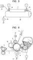
- the electrophotographic apparatus according to the present invention is characterized by having at least the above charging member, an exposure unit and a developing assembly.
- a charging member which can stably electrostatically charge the electrophotographic photosensitive member and also can keep the surface of the electrophotographic photosensitive member from coming to wear non-uniformly.
- a process cartridge and an electrophotographic apparatus are also obtained which can stably form high-grade electrophotographic images.
- Fig. 1A is a sectional view showing an example of layer configuration of the charging member (roller shaped) according to the present invention.
- Fig. 1A shows a cross section of the charging member according to the present invention.
- the charging member has a conductive substrate 1 and a conductive resin layer 3 which covers the former on its peripheral surface.
- the conductive resin layer 3 contains a binder, conductive fine particles and bowl-shaped resin particles.
- the conductive resin layer 3 may be formed of a first conductive resin layer 31 and a second conductive resin layer 32.
- a conductive elastic layer 2 may be formed between the conductive substrate 1 and the conductive resin layer 3.
- Figs. 2A and 2B are enlarged sectional views of surface portions of the charging member according to the present invention.
- the conductive resin layer 3 as a surface layer is incorporated therein with bowl-shaped resin particles 61 standing unexposed to the surface of the charging member.
- concavities 52 derived from openings 51 of the bowl-shaped resin particles and protrusions 54 derived from edges 53 of the openings of the bowl-shaped resin particles stand formed on the surface of the charging member.
- Figs. 2C and 2D show examples in which each conductive resin layer 3 is formed of the first conductive resin layer 31 and the second conductive resin layer 32.
- first conductive resin layer 31 bowl-shaped resin particles 61 are present in such a way that its openings are exposed to the surface of the first conductive resin layer 31 and edges of the openings constitute protrusions.
- the surface of such a first conductive resin layer is covered with the second conductive resin layer 32 so that the bowl-shaped resin particles 61 may stand unexposed to the surface.
- the second conductive resin layer 32 is formed along inner walls of the bowl-shaped resin particles 61, and hence concavities derived from the openings of the bowl-shaped resin particles are formed on the surface of the second conductive resin layer constituting the surface of the charging member. Further, the second conductive resin layer covers the edges of the openings of the bowl-shaped resin particles 61, thus protrusions derived from the edges are formed on the surface of the second conductive resin layer.
- FIG. 8 is an enlarged diagrammatic view of a nip between the charging member according to the present invention and an electrophotographic photosensitive member.
- the edges 53 of the openings of bowl-shaped resin particles 61 are considered to deform elastically in the directions of arrows A in virtue of the pressure of their contact with an electrophotographic photosensitive member 803.
- the reason why the charging member according to the present invention can not easily scrape off the surface of the electrophotographic photosensitive member is that the pressure of contact that is to be applied to the electrophotographic photosensitive member stands lessened because the edges 53 of the openings of bowl-shaped resin particles have elastically deformed.
- the present inventors have also reached a finding that such a phenomenon of discharge inside the nip takes place because the inner walls of the bowl-shaped resin particles are covered (lined) with the conductive resin layer.
- each top (or peak top) 55 of protrusions 54 derived from the edges of openings of the bowl-shaped resin particles and each bottom 56 of concavities 52 derived from the openings of the bowl-shaped resin particles may preferably be in a top-to-bottom distance 57 of from 5 ⁇ m or more to 100 ⁇ m or less, and particularly preferably from 8 ⁇ m or more to 80 ⁇ m or less. Inasmuch as the top-to-bottom distance is set within this range, the pressure of contact of the charging member with the electrophotographic photosensitive member can more surely be lessened, and the empty spaces inside the nip between them can be retained.
- the ratio of maximum diameter 58 in each particle of the bowl-shaped resin particles to the top-to-bottom distance 57 between the top 55 of each protrusion and the bottom 56 of each concavity i.e., the value of (maximum diameter)/(top-to-bottom distance) may preferably be from 0.8 or more to 3.0 or less. Inasmuch as the ratio is set within this range, the aforesaid pressure of contact can more surely be lessened, and the empty spaces inside the nip can be retained.
- the conductive resin layer may preferably have a ten-point average surface roughness (Rzjis) of from 5 ⁇ m or more to 65 ⁇ m or less, and particularly preferably from 10 ⁇ m or more to 50 ⁇ m or less. Its surface may also preferably have a hill-to-dale average distance (Sm) of from 30 ⁇ m or more to 200 ⁇ m or less, and particularly preferably from 40 ⁇ m or more to 150 ⁇ m or less.
- Rzjis ten-point average surface roughness
- Sm hill-to-dale average distance
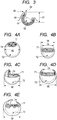
- bowl-shaped resin particles used in the present invention are shown in Figs. 4A to 4E . That is, "bowl-shaped” in the present invention refers to the shape that the particles have openings 71 and have roundish concavities 72 at the openings.
- the openings may have, as shown in Figs. 4A and 4B , flat edges, or, as shown in Figs. 4C to 4D , uneven edges.
- the bowl-shaped resin particles may preferably have, in each particle thereof, a maximum diameter of from 5 ⁇ m or more to 150 ⁇ m or less, and particularly preferably from 8 ⁇ m or more to 120 ⁇ m or less. Inasmuch as the maximum diameter is within this range, the discharge inside the nip can more surely be made to takes place.
- the ratio of the maximum diameter 58 in each particle of the bowl-shaped resin particles to minimum diameter 74 in each of the openings i.e., the value of (maximum diameter)/(opening minimum diameter) in each particle of the bowl-shaped resin particles may preferably be from 1.1 or more to 4.0 or less. Inasmuch as the ratio is so set, the aforesaid pressure of contact can more surely be lessened, and the empty spaces inside the nip can be retained.
- Peripheral edges of the openings of the bowl-shaped resin particles have a difference between outer diameter and inner diameter, of from 0.1 ⁇ m or more to 3 ⁇ m or less, and preferably from 0.2 ⁇ m or more to 2 ⁇ m or less. Inasmuch as the difference is within this range, the aforesaid pressure of contact can more surely be lessened. Also, it is further preferable that such a difference between outer diameter and inner diameter is formed over the whole particles and substantially uniformly. What is meant by “substantially uniform” is that the difference is in the range of within ⁇ 50% of average value.
- any known rubber or resin may be used.
- the rubber it may include, e.g., natural rubbers or those which have been subjected to vulcanization treatment, and synthetic rubbers.
- the synthetic rubbers may include the following: Ethylene-propylene rubber, styrene-butadiene rubber (SBR), silicone rubbers, urethane rubbers, isoprene rubber (IR), butyl rubber, acrylonitrile-butadiene rubber (NBR), chloroprene rubber (CR), acrylic rubbers, epichlorohydrin rubber and fluorine rubbers.
- SBR styrene-butadiene rubber
- silicone rubbers silicone rubbers
- urethane rubbers urethane rubbers
- IR isoprene rubber
- NBR acrylonitrile-butadiene rubber
- CR chloroprene rubber
- acrylic rubbers epichlorohydrin rubber and fluorine rubbers.
- any of resins such as thermosetting resins
- fluorine resins preferred are fluorine resins, polyamide resins, acrylic resins, polyurethane resins, silicone resins and butyral resins. Any of these may be used alone, or may be used in the form of a mixture of two or more types. Also, monomers which are raw materials for the binder may be copolymerized to make a copolymer.
- the conductive resin layer is formed of the first conductive resin layer and the second conductive resin layer, it is preferable to use the rubber as the binder used for the first conductive resin layer. This is because the pressure to be applied to the bowl-shaped resin particles shows a tendency to be more readily lessened.
- the conductive resin layer may be formed by curing or cross-linking a mixture obtained by adding a cross-linking agent to raw materials of a binder made into a prepolymer. In the present invention, such a mixture is hereinafter also termed as the binder to provide a description.
- the conductive resin layer contains known conductive fine particles in order to bring out its electrical conductivity.
- the conductive fine particles may include fine metal oxide particles, fine metal particles and carbon black. Any of these conductive fine particles may be used alone or in combination of two or more types.
- the conductive fine particles in the conductive resin layer may be in a content of approximately from 2 parts by mass to 200 parts by mass, and particularly from 5 parts by mass to 100 parts by mass, based on 100 parts by mass of the binder.
- the binder and conductive fine particles used in the first conductive resin layer and second conductive resin layer may be the same or may be different.
- the conductive resin layer contains the bowl-shaped resin particles standing unexposed to the surface, and hence it is preferable for the first conductive resin layer and second conductive resin layer to have adherence to and affinity for each other.
- a cover layer in which conductive fine particles and hollow resin particles have been dispersed in the binder (hereinafter also “preliminary cover layer”) is formed on the conductive substrate. Then, its surface is sanded so as to cut away part of the hollow resin particles to make them bowl-shaped. Thus, the concavities derived from the openings of the bowl-shaped resin particles and the protrusions derived from the edges of the openings of the bowl-shaped resin particles are formed on the surface (hereinafter also “uneven-surface profile coming from the openings of the bowl-shaped resin particles”).
- the preliminary cover layer is sanded in this way to first form the first conductive resin layer. Further, on its surface, the second conductive resin layer is formed. This enables the bowl-shaped resin particles to stand unexposed to the surface.
- a method is available in which a coating of a conductive resin composition in which hollow particles having a gas in their interiors stand dispersed together with the binder and the conductive fine particles is formed on the conductive substrate and then the coating formed is, e.g., dried, cured or cross-linked.
- a material used for the hollow resin particles it may include the known resins described previously.
- a method may be exemplified which makes use of what is called thermally expandable microcapsules the particles of which contain in their interiors an encapsulated substance, where heat is applied to make the encapsulated substance expand to come into the hollow resin particles.
- a conductive resin composition is prepared in which the thermally expandable microcapsules stand dispersed together with the binder and the conductive fine particles, and a layer of this composition is formed on the conductive substrate and then, e.g., dried, cured or cross-linked.
- the encapsulated substance may be made to expand by the heat supplied when the binder used in the preliminary cover layer is dried, cured or cross-linked, to form the hollow resin particles.
- their particle diameter and so forth may also be controlled by controlling temperature conditions and so forth.
- thermoplastic resin As the binder, it is necessary to use a thermoplastic resin as the binder.
- the thermoplastic resin are given below: Acrylonitrile resin, vinyl chloride resin, vinylidene chloride resin, methacrylic acid resin, styrene resins, urethane resins, amide resins, methacrylonitrile resin, acrylic acid resin, acrylate resins, methacrylate resins and so forth.
- a thermoplastic resin composed of at least one selected from acrylonitrile resin, vinylidene chloride resin and methacrylonitrile resin, as having a low gas permeability and exhibiting a high impact resilience. Any of these thermoplastic resins may be used alone or in combination of two or more types. Further, monomers for any of these thermoplastic resins may be copolymerized so as to be used as a copolymer.
- thermoplastic resin used as the binder may include, e.g., the following: Low-boiling liquids such as propane, propylene, butane, normal butane, isobutane, normal pentane and isopentane; and high-boiling liquids such as normal hexane, isohexane, normal heptane, normal octane, isooctane, normal decane and isodecane.
- Low-boiling liquids such as propane, propylene, butane, normal butane, isobutane, normal pentane and isopentane
- high-boiling liquids such as normal hexane, isohexane, normal heptane, normal octane, isooctane, normal decane and isodecane.
- the thermally expandable microcapsules may be produced by any known production process such as a suspension polymerization process, an interfacial polymerization process, an interfacial precipitation process or a solvent evaporation process.
- a method may be exemplified in which a polymerizable monomer(s), the substance to be entrapped in thermally expandable microcapsules and a polymerization initiator are mixed, the mixture obtained is dispersed in an aqueous medium containing a surface-active agent or a dispersion stabilizer and thereafter suspension polymerization is carried out.
- a compound having a reactive group capable of reacting with functional groups of the polymerizable monomer, an organic filler and so froth may also be added.
- the polymerizable monomer it may be exemplified by the following: Acrylonitrile, methacrylonitrile, ⁇ -chloroacrylonitrile, ⁇ -ethoxyacrylonitrile, fumaronitrile, acrylic acid, methacrylic acid, itaconic acid, maleic acid, fumaric acid, citraconic acid, vinylidene chloride, vinyl acetate, acrylates (such as methyl acrylate, ethyl acrylate, n-butyl acrylate, isobutyl acrylate, t-butyl acrylate, isobornyl acrylate, cyclohexyl acrylate and benzyl acrylate), methacrylates (such as methyl methacrylate, ethyl methacrylate, n-butyl methacrylate, isobutyl methacrylate, t-butyl methacrylate, isobornyl methacrylate, cyclohexyl meth
- any of known peroxide initiators and azo initiators may be used. Of these, azo initiators are preferred. Specific examples of the azo initiators are given below: 2,2'-Azobisisobutyronitrile, 1,1'-azobiscyclohexane-1-carbonitrile, 2,2'-azobis(4-methoxy-2,4-dimethyl)valeronitrile and 2,2'-azobis(2,4-dimethyl)valeronitrile. In particular, 2,2'-azobisisobutyronitrile is preferred. Where the polymerization initiator is used, it may preferably be in an amount of from 0.01 part by mass to 5 parts by mass based on 100 parts by mass of the polymerizable monomer.
- any of anionic surface-active agents, cationic surface-active agents, nonionic surface-active agents, amphoteric surface-active agents and high-molecular type dispersants may be used.
- the surface-active agent may preferably be in an amount of from 0.01 part by mass to 10 parts by mass based on 100 parts by mass of the polymerizable monomer.
- the dispersion stabilizer it may include organic fine particles (such as fine polystyrene particles, fine polymethyl methacrylate particles, fine polyacrylic acid particles and fine polyepoxide particles, silica (such as colloidal silica), calcium carbonate, calcium phosphate, aluminum hydroxide, barium carbonate and magnesium hydroxide.
- the dispersion stabilizer it may preferably be in an amount of from 0.01 part by mass to 20 parts by mass based on 100 parts by mass of the polymerizable monomer.
- the suspension polymerization may preferably be carried out in a closed system, using a pressure container.
- the suspension polymerization may also be carried out after materials have been brought to suspension by means of a dispersion machine or the like and then moved to the pressure container, or the materials may be brought to suspension in the pressure container.
- Polymerization temperature may preferably be from 50°C to 120°C.
- the polymerization may be carried out under atmospheric pressure, but may preferably be carried out under application of pressure (under pressure produced by adding 0.1 MPa to 1 MPa to atmospheric pressure) in order not to make gaseous the substance to be entrapped in the thermally expandable microcapsules.
- the product may be subjected to solid-liquid separation and washing or the like by centrifugation, filtration or the like.
- the product obtained may thereafter be dried and pulverized at a temperature not higher than the softening temperature of the resin constituting the thermally expandable microcapsules. It may be dried and pulverized by known methods, where any of an airstream drier, a following-wind air drier, Nauta mixer and the like may be used. It may also be dried and pulverized simultaneously by means of a pulverization drier or the like.
- the surface-active agent and the dispersion stabilizer may be removed by repeating washing, filtration and so forth after production.
- the preliminary cover layer may include electrostatic spray coating, dip coating, roll coating, a method in which a sheet-shaped or tube-shaped layer formed in a stated layer thickness is bonded to or covered on the conductive substrate, and a method in which the material is cured and molded into a stated shape in a mold. Also, especially in the case when the binder is a rubber, the conductive substrate and an unvulcanized rubber composition may integrally be extruded by means of an extrusion equipment having a cross-head, to produce the cover layer on the substrate.
- the cross-head is an extruder die used in the state it is provided at the tip of a cylinder of an extruder, which is used in order to make up cover layers of electric wires or thin metal threads. Thereafter, the layer formed is, e.g., dried, cured or cross-linked and thereafter the surface of the resultant preliminary cover layer is sanded so as to cut away part of the hollow resin particles to make them bowl-shaped.
- cylindrical sanding or tape sanding may be used.
- a cylindrical sander it may be exemplified by an NC cylindrical sander of a traverse system and an NC cylindrical sander of a plunge cutting system.
- the tape sanding In order to cut away the protrusions deriving from the hollow resin particles, it is preferable to use the tape sanding. This is because the pressure applied to the charging member at the time of sanding is relatively small.
- a specific example of a sanding tape and sanding conditions are described below which are used when part of the protrusions of the preliminary cover layer is cut away by using a tape sanding method.
- the sanding tape is obtained by coating a sheet-like base material with a coating liquid prepared by dispersing sanding abrasive grains in a resin.
- the sanding abrasive grains may be exemplified by particles of aluminum oxide, chromium oxide, silicon carbide, iron oxide, diamond, cerium oxide, corundum, silicon nitride, silicon carbide, molybdenum carbide, tungsten carbide, titanium carbide and silicon oxide.
- the sanding abrasive grains may preferably have an average particle diameter of from 0.01 ⁇ m or more to 50 ⁇ m or less, and much preferably from 1 ⁇ m or more to 30 ⁇ m or less.
- the average particle diameter of the sanding abrasive grains is the median diameter D50 as measured by centrifugal sedimentation.
- the sanding tape having the sanding abrasive grains within the desired range may be of grain count which may preferably be in the range of from 500 or more to 20,000 or less, and much preferably from 1,000 or more to 10,000 or less.
- Examples of the sanding tape are given below: MAXIMA LAP, MAXIMA T Type (trade name; available from Ref-Lite Co., Ltd.); LAPIKA (trade name; available from Kovax Co., Ltd.); a lapping film MICROFINISHING FILM (trade name; available from Sumitomo 3M Limited.); a lapping film MIRROR FILM (trade name; available from Sankyo Rikagaku Co., Ltd.); and MIPOX, available from Nippon Microcoating K.K.).
- the sanding tape may preferably be fed at a rate of from 10 mm/min or more to 500 mm/min or less, and particularly preferably from 50 mm/min or more to 300 mm/min or less.
- the sanding tape may preferably be pressed against the preliminary cover layer at a pressure of from 0.01 MPa or more to 0.4 MPa or less, and particularly preferably from 0.1 MPa or more to 0.3 MPa or less.
- a back-up roller may be brought into touch with the preliminary cover layer through the sanding tape.
- the sanding processing may be carried out over a plurality of times.
- a member on which the preliminary cover layer has been formed has a shape of being rotatable (e.g., in the case of the shape of a roller), it may preferably be set at a number of revolutions of from 10 rpm or more to 1,000 rpm or less, and particularly preferably from 50 rpm or more to 800 rpm or less.
- the preliminary cover layer has thickness more than 5 times the volume-average particle diameter of the hollow resin particles, it may come about that the protrusions derived from the hollow resin particles are not formed on the surface of the preliminary cover layer.
- the difference in sandability (capability of being sanded) between the hollow resin particles and the preliminary cover layer may be utilized to form the uneven-surface profile coming from the openings of the bowl-shaped resin particles.
- the hollow resin particles entrap a gas in their interiors, and hence have a high impact resilience.
- a rubber or resin is selected which has a relatively low impact resilience and also has a small elongation.
- the preliminary cover layer kept in this state is sanded, whereupon only part of the hollow resin particles can be cut away to make them into the bowl-shaped resin particles.
- the openings of the bowl-shaped resin particles can be formed on the surface of the preliminary cover layer.
- This method is a method in which the difference in sandability between the hollow resin particles and the preliminary cover layer is utilized to form the concavities derived from the openings and the protrusions derived from the edges of the openings, and hence it is preferable to use a rubber as the binder used in the preliminary cover layer.
- acrylonitrile butadiene rubber, styrene butadiene rubber or butadiene rubber may preferably be used, which has a low impact resilience and also has a small elongation.
- a resin having a polar group are preferable from the viewpoint that shells can have a low gas permeability and have a high impact resilience.
- a resin may include a resin having a unit represented by the following formula (1). Further, from the viewpoint of readiness to control the sandability, it is much preferable for the resin to have both the unit represented by the formula (1) and a unit represented by the following formula (5).
- A is at least one selected from the following formulas (2) to (4); and R1 is a hydrogen atom or an alkyl group having 1 to 4 carbon atom(s).
- Formula (2) -C ⁇ N wherein R2 is a hydrogen atom or an alkyl group having 1 to 4 carbon atom(s); R3 is a hydrogen atom or an alkyl group having 1 to 10 carbon atom(s); and R2 and R3 may have the same structures or different structures.
- cylindrical sanding or tape sanding may be used, but preferably on condition that the surface is more speedily sanded because it is necessary to remarkably bring out the difference in sandability between the materials. From this viewpoint, it is much preferable to use the cylindrical sanding. Of the cylindrical sanding, it is further preferable to use a plunge cutting system, from the viewpoint that the surface can simultaneously be sanded in its lengthwise direction and sanding time can be shortened.
- the step of spark-out (the step of sanding at a penetration rate of 0 mm/min) carried out conventionally from the viewpoint of giving uniform sanded surface is set as possible as short in time, or not carried out at all.
- ranges that are preferable as conditions for sanding the preliminary cover layer when a cylindrical sander of the plunge cutting system is used are shown below.
- the number of revolutions of a cylindrical sand grinding wheel may preferably be from 1,000 rpm or more to 4,000 rpm or less, and particularly preferably from 2,000 rpm or more to 4,000 rpm.
- the rate of penetration into the preliminary cover layer may preferably be from 5 mm/min or more to 30 mm/min or less, and particularly preferably from 10 mm/min or more.
- the step of leveling the sanded surface may be provided, which may preferably be done at a penetration rate of from 0.1 mm/min or more to 0.2 mm/min or less within 2 seconds.
- the step of spark-out (the step of sanding at a penetration rate of 0 mm/min) may preferably be done for 3 seconds or less.
- the member on which the preliminary cover layer has been formed has a shape of being rotatable (e.g., in the case of the shape of a roller), it may preferably be set at a number of revolutions of from 50 rpm or more to 500 rpm or less, and particularly preferably from 200 rpm or more to 500 rpm. Setting the conditions as above enables the uneven-surface profile coming from the openings of the bowl-shaped resin particles, to be more readily formed on the surface of the first conductive resin layer.
- the first conductive resin layer is covered on the surface thereof with a conductive resin composition, followed by drying, curing, cross-linking or the like to form the second conductive resin layer.
- a covering method the method described previously may be used. It is necessary to provide the surface that has reflected the uneven-surface profile coming from the openings, and edges thereof, of the bowl-shaped resin particles. Hence, it is preferable for the second conductive resin layer to be relatively thin.
- the second conductive resin layer may have a thickness of approximately 50 ⁇ m or less, and particularly 30 ⁇ m or less. Accordingly, of the above covering method, a method is much preferable in which the second conductive resin layer is formed by electrostatic spray coating, dip coating, roll coating or the like. Where such a coating method is used, a coating liquid is prepared in which the conductive fine particles stand dispersed in the binder, which is used for the coating.
- the conductive fine particles and the bowl-shaped resin particles are dispersed in the binder to prepare a conductive resin composition.
- the conductive substrate is covered thereon with the composition obtained, followed by drying, curing, cross-linking or the like to form the conductive resin layer.
- the bowl-shaped resin particles may be produced by cutting away part of the hollow resin particles described previously. Instead, a polymerizable monomer may be so polymerized as for resin particles to become bowl-shaped in the course of their production.
- a method for so producing the resin particles as to become bowl-shaped a method is available in which the polymerizable monomer is subjected to suspension polymerization in the presence of a cross-linking agent, a hydrophobic liquid and a polymerization initiator and with stirring in water to prepare particles which entrap the hydrophobic liquid in their polymer films of a polymer.
- hydrophobic liquid is entrapped in the interiors of the particles of the polymer formed during polymerization, and the polymer deforms during the polymerization to come into bowl-shaped resin particles.
- the polymerization initiator may include the following: Styrene, methylstyrene, vinyl toluene, methacrylates, acrylates, vinyl acetate, acrylonitrile, vinyl chloride, vinylidene chloride, chloroprene, isoprene, butadiene, acrolein, acrylamide, allyl alcohol, vinyl pyridine, vinyl benzoate, allyl benzoate, and mixtures of any of these.
- the cross-linking agent may be exemplified by divinylbenzene, ethylene dimethacrylate, triethylene glycol dimethacrylate, 1,3-butylene dimethacrylate, allyl methacrylate, and trimethylol propane trimethacrylate. Two or more types of these may be used in combination.
- the cross-linking agent may be in an amount of from 0.1% by mass to 30% by mass, and particularly from 1% by mass to 20% by mass, based on 100% by mass of the polymerizable monomer. Inasmuch as the amount of the cross-linking agent is set within this range, the particles can appropriately be deformed.
- the hydrophobic liquid may be exemplified by hydrocarbon oils, animal oils, vegetable oils, esters, ethers and silicones.
- the hydrophobic liquid may be in an amount of from 15% by mass or more to 100% by mass or less, based on 100% by mass of the polymerizable monomer. Inasmuch as the amount of the hydrophobic liquid is set within this range, the resin particles can readily become bowl-shaped.
- a radical catalyst may preferably be used, as exemplified by benzoyl peroxide, methyl ethyl ketone peroxide, t-butyl peroxide, 2,2'-azobisisobutyronitrile and 2,2'-azobis(2,4-dimethyl)valeronitrile.
- a suspension stabilizer may be added, as exemplified by polyvinyl alcohol, gelatin, methyl cellulose, sodium alginate, calcium phosphate, colloidal silica, bentonite and aluminum oxide.
- An anti-coagulant such as titanium oxide or calcium carbonate may also be added thereto so as for the particles not to coagulate at the time of drying.
- Polymerization temperature may commonly preferably be from 50°C to 95°C.
- the particle diameter of fine particles is influenced by the rate of stirring, and hence the stirring may preferably be carried out at from 50 rpm to 500 rpm, and particularly preferably from 100 rpm to 300 rpm.
- Polymerization time may preferably be from 3 hours to 24 hours.
- the particles formed may preferably be dried after they have been taken out of the water, and the drying may preferably be carried out at a temperature lower than the softening temperature of the polymer, i.e., at from 30°C to 90°C.
- the bowl-shaped resin particles are mixed together with the binder and the conductive fine particles to prepare a conductive resin composition.
- the conductive substrate is covered thereon with this conductive resin composition to form the conductive resin layer.
- the conductive resin layer may preferably have a layer thickness that is not more than 5 times, and particularly preferably not more than 3 times, the maximum diameter of the bowl-shaped resin particles.
- any volatile component from the coating can volatilize at a higher rate, and the flow of the volatile component volatilizing at a higher rate enables the openings of the bowl-shaped resin particles to face toward the surface side of the conductive resin layer to form the uneven-surface profile.
- the rate of volatilization it is preferable to use in the coating liquid the solvent described previously.
- dispersive components other than the bowl-shaped resin particles e.g., the conductive fine particles are mixed in the binder together with glass beads of 0.8 mm in diameter, and dispersed therein over a period of from 12 hours to 36 hours by means of a paint shaker dispersion machine.
- the bowl-shaped resin particles are added thereto and dispersed therein.
- As dispersion time it may preferably be from 2 minutes or more to 30 minutes or less.
- the dispersion formed is so controlled as to have a viscosity of from 3 mPa to 30 mPa, and particularly preferably from 3 mPa to 20 mPa to obtain a coating liquid.
- the conductive substrate is coated thereon with this coating liquid by dipping or the like to form such a coating thereof that may provide a dried-layer thickness of from 1 ⁇ m to 50 ⁇ m, and particularly preferably from 5 ⁇ m to 30 ⁇ m.
- This coating is dried at a temperature of from 20°C to 50°C, and particularly at a temperature of from 30°C to 50°C.
- treatment such as curing or cross-linking may be carried out.
- the dispersion means described previously may be used as a method for dispersing the conductive fine particles and so forth in the binder.
- the layer thickness may be measured by the method described previously.
- the above bowl-shaped resin particles in the conductive resin layer may preferably be in a content of from 2 parts by mass or more to 120 parts by mass or less, and particularly preferably from 5 parts by mass or more to 100 parts by mass or less, based on 100 parts by mass of the binder. Setting their content within this range enables easier formation of the uneven-surface profile coming from the openings of the bowl-shaped resin particles.
- the conductive resin layer in the present invention may contain, in addition to the conductive fine particles described previously, an ionic conducting agent and insulating particles.
- the conductive resin layer may preferably have a volume resistivity of approximately from 1 ⁇ 10 2 ⁇ cm or more to 1 ⁇ 10 16 ⁇ cm or less in an environment of temperature 23°C/humidity 50%RH. Setting its volume resistivity within this range makes it easier for the electrophotographic photosensitive member to be appropriately charged by discharging.
- the volume resistivity of the conductive resin layer is determined in the following way. First, from the charging member, the conductive resin layer is cut out in the shape of an oblong card of about 5 mm in length, about 5 mm in width and about 1 mm in thickness. A metal is vacuum-deposited on its both sides to make an electrode and a guard electrode to obtain a sample for measurement. Where the conductive resin layer is too thin to be cut out, an aluminum sheet is coated thereon with a conductive resin composition for forming the conductive resin layer to form a coating film, and the metal is vacuum-deposited on the coating film surface to obtain a sample for measurement.
- a voltage of 200 V is applied by using a micro-current meter (trade name: ADVANTEST R8340A Ultra-high Resistance Meter; manufactured by Advantest Co., Ltd.). Then, electric current after 30 seconds is measured, and calculation is made from layer thickness and electrode area to find the volume resistivity.
- the volume resistivity of the conductive resin layer may be controlled by using the conductive fine particles and ionic conducting agent described previously. Also, the conductive fine particles may have an average particle diameter of approximately from 0.01 ⁇ m to 0.9 ⁇ m, and particularly from 0.01 ⁇ m to 0.5 ⁇ m.
- the conductive fine particles in the conductive resin layer may be in a content of approximately from 2 parts by mass to 80 parts by mass, and particularly from 20 parts by mass to 60 parts by mass based on 100 parts by mass of the binder.
- the conductive substrate used in the charging member of the present invention is one having electrical conductivity and having the function to support the conductive resin layer and so forth provided thereon.
- a material therefor it may include, e.g., metals such as iron, copper, stainless steel, aluminum and nickel, and alloys of any of these.
- a conductive elastic layer may be formed between the conductive substrate and the conductive resin layer.
- a binder used to form the conductive elastic layer any known rubber or resin may be used. From the viewpoint of securing a sufficient nip between the charging member and the electrophotographic photosensitive member, it is preferable for the layer to have a relatively low elasticity, and is much preferable to use a rubber. As the rubber, it may be exemplified by the rubber described previously.
- the conductive elastic layer may preferably have a volume resistivity of from 10 2 ⁇ cm or more to 10 10 ⁇ cm or less in an environment of temperature 23°C/humidity 50%RH.
- the volume resistivity of the conductive elastic layer may be controlled by appropriately adding to the binder a conducting agent such as carbon black, a conductive metal oxide, an alkali metal salt or an ammonium salt. Where the binder is a polar rubber, it is particularly preferable to use an ammonium salt.
- the conductive elastic layer may also be incorporated with additives such as a softening oil and a plasticizer and the above insulating particles, in addition to the conductive fine particles and in order to control hardness and so forth.
- the conductive elastic layer may also be provided by bonding it with an adhesive, between the conductive substrate and the conductive resin layer. As the adhesive, it is preferable to use a conductive adhesive.
- the charging member according to the present invention may at least have the conductive substrate and conductive resin layer described above, and may also have any shape such as a roller-shaped one or a flat-plate-shaped one.
- a charging roller is used to describe it in detail.
- the layer lying directly thereon (the conductive elastic layer) may be bonded with an adhesive.
- the adhesive may preferably be electrically conductive.
- it may have a known conducting agent.
- a binder of the adhesive it may include thermosetting resins and thermoplastic resins, and any known resins may be used which are of a urethane type, an acrylic type, a polyester type, a polyether type or an epoxy type.
- the conducting agent for providing the adhesive with electrical conductivity it may be selected from the conductive fine particles and ionic conducting agent described previously, any of which may be used alone or in combination of two or more types.
- the charging member of the present invention may usually much preferably have an electrical resistance value of from 1 ⁇ 10 3 ⁇ or more to 1 ⁇ 10 10 ⁇ or less in an environment of temperature 23°C/humidity 50%RH.
- the charging roller of the present invention may preferably be in a crown shape in which the roller is thickest at the middle in its lengthwise direction and is thinner as it comes to the both ends in its lengthwise direction.
- the difference in external diameter between that at the middle portion and that at positions 90 mm away from the middle portion may preferably be from 30 ⁇ m or more to 200 ⁇ m or less.
- the surface of the charging roller may preferably have a hardness of 90° or less, and much preferably from 40° or more to 80° or less, as microhardness (MD-1 Model). Setting its hardness within this range makes it easy to stabilize its contact with the electrophotographic photosensitive member, and enables stable in-nip discharge.
- the charging member of the present invention may be used as a component part of an electrophotographic apparatus.
- This electrophotographic apparatus has at least a charging member, an exposure unit and a developing assembly.
- the construction of an example of an electrophotographic apparatus having the charging member of the present invention is schematically shown in Fig. 6 .
- the electrophotographic apparatus has an electrophotographic photosensitive member, a charging assembly for the electrophotographic photosensitive member, a latent image forming unit, a developing assembly, a transfer assembly, a cleaning unit which collects ay transfer residual toner remaining on the electrophotographic photosensitive member, a fixing assembly and so forth.
- An electrophotographic photosensitive member 4 is of a rotating drum type having a photosensitive layer on a conductive substrate, and is rotatingly driven at a stated peripheral speed (process speed) in the direction shown by an arrow.
- the charging assembly has a charging roller 5 of a contact system which is provided in contact with the electrophotographic photosensitive member 4 at a stated pressing force.
- the charging roller 5 is follow-up rotated with the rotation of the electrophotographic photosensitive member 4, and a stated direct-current voltage is applied thereto from a charging power source 19 to charge the electrophotographic photosensitive member 4 electrostatically to a stated potential.
- a latent image forming unit 11 which forms an electrostatic latent image on the electrophotographic photosensitive member 4
- an exposure unit such as a laser beam scanner is used, for example.
- the electrophotographic photosensitive member 4 thus charged uniformly is exposed to light in accordance with image information to form the electrostatic latent image thereon.
- the developing assembly has a developing sleeve or developing roller 6 which is provided in proximity to or in contact with the electrophotographic photosensitive member 4.
- the electrostatic latent image is developed by reverse development with a toner having electrostatically been processed to have the same polarity as charge polarity of the electrophotographic photosensitive member, to form a toner image thereon.
- the transfer assembly has a contact type transfer roller 8.
- the toner image is transferred from the electrophotographic photosensitive member to a transfer material 7 such as plain paper (the transfer material is transported by a paper feed system having a transport member).
- the cleaning unit has a blade type cleaning member 10 and a collecting container 14, and mechanically scrapes off and collects any transfer residual toner remaining on the electrophotographic photosensitive member after transfer.
- a cleaning-at-development system which collects the transfer residual toner with the developing assembly may be employed so as to omit the cleaning unit.
- a fixing assembly 9 is constituted of a roll or the like to be kept heated, and fixes to the transfer material 7 the toner image having been transferred thereto, which is then delivered out of the machine.
- the process cartridge according to the present invention is characterized by having the above charging member and an electrically chargeable body (an electrophotographic photosensitive member) provided in contact with the charging member which are integrally joined, and being so constituted as to be detachably mountable to the main body of the electrophotographic apparatus.
- Production Examples 1 to 69 are given below. These production examples are itemized as follows: Production Examples 1 to 38, 44 and 55 are production examples for the hollow resin particles. Production Examples 39 to 43 are production examples for the bowl-shaped resin particles. Production Examples 46 to 49 are production examples for conductive rubber compositions containing the hollow resin particles. Production Example 50 is a production example for composite conductive fine particles. Production Example 51 is a production example for surface-treated titanium oxide particles. Production Examples 52 to 59 are production examples for conductive resin coating liquids 1 to 8 not containing any hollow resin particles. Production Examples 60 to 68 are production examples for conductive resin coating liquids 9 to 17 containing the hollow resin particles. Production Example 69 is a production example for a conductive rubber composition. Average particle diameter of the resin particles refers to volume-average particle diameter.
- the liquid dispersion obtained was stirred and mixed for 3 minutes by means of a homogenizer, which was then fed into a polymerization reaction vessel the interior of which had been displaced with nitrogen, to carry out reaction at 60°C for 20 hours with stirring at 200 rpm to prepare a reaction product.
- the reaction product obtained was repeatedly filtered and washed with water, followed by drying at 80°C for 5 hours to make hollow resin particles.
- the hollow resin particles obtained were disintegrated and classified by means of a sonic-wave classifier to obtain resin particles 1 having an average particle diameter of 12 ⁇ m.
- Resin particles were made in the same way as those in Production Example 1 except that the colloidal silica was added in an amount changed to 4.5 parts by mass. The particles obtained were also classified in the same way to obtain resin particles 2 having an average particle diameter of 50 ⁇ m.
- Particles having an average particle diameter of 60 ⁇ m which were only different in particle diameter from those classified in Production Example 2 were obtained as resin particles 3.
- Particles having an average particle diameter of 18 ⁇ m which were only different in particle diameter from those classified in Production Example 1 were obtained as resin particles 4.
- Particles having an average particle diameter of 10 ⁇ m which were only different in particle diameter from those classified in Production Example 1 were obtained as resin particles 5.
- Particles having an average particle diameter of 40 ⁇ m which were only different in particle diameter from those classified in Production Example 2 were obtained as resin particles 6.
- Particles having an average particle diameter of 15 ⁇ m which were only different in particle diameter from those classified in Production Example 1 were obtained as resin particles 7.
- Resin particles were made in the same way as those in Production Example 2 except that the polymerizable monomers were changed for 80 parts by mass of acrylonitrile and 20 parts by mass of methyl methacrylate. The particles obtained were also classified in the same way to obtain resin particles 8 having an average particle diameter of 30 ⁇ m.
- Resin particles were made in the same way as those in Production Example 8 except that the colloidal silica was added in an amount changed to 9 parts by mass.
- the particles obtained were also classified in the same way to obtain resin particles 9 having an average particle diameter of 10 ⁇ m.
- Particles having an average particle diameter of 15 ⁇ m which were only different in particle diameter from those classified in Production Example 9 were obtained as resin particles 10.
- Particles having an average particle diameter of 50 ⁇ m which were only different in particle diameter from those classified in Production Example 8 were obtained as resin particles 11.
- Resin particles were made in the same way as those in Production Example 1 except that the polymerizable monomers were changed for 45 parts by mass of methacrylonitrile and 55 parts by mass of methyl acrylate. The particles obtained were also classified in the same way to obtain resin particles 12 having an average particle diameter of 25 ⁇ m.
- Particles having an average particle diameter of 15 ⁇ m which were only different in particle diameter from those classified in Production Example 12 were obtained as resin particles 13.
- Resin particles were made in the same way as those in Production Example 12 except that the colloidal silica was added in an amount changed to 4.5 parts by mass. The particles obtained were also classified in the same way to obtain resin particles 14 having an average particle diameter of 30 ⁇ m.
- Particles having an average particle diameter of 40 ⁇ m which were only different in particle diameter from those classified in Production Example 14 were obtained as resin particles 15.
- Resin particles were made in the same way as those in Production Example 2 except that the polymerizable monomers were changed for 45 parts by mass of acrylamide and 55 parts by mass of methacrylamide. The particles obtained were also classified in the same way to obtain resin particles 16 having an average particle diameter of 40 ⁇ m.
- Particles having an average particle diameter of 45 ⁇ m which were only different in particle diameter from those classified in Production Example 16 were obtained as resin particles 17.
- Particles having an average particle diameter of 30 ⁇ m which were only different in particle diameter from those classified in Production Example 16 were obtained as resin particles 18.
- Resin particles were made in the same way as those in Production Example 1 except that the polymerizable monomers were changed for 37.5 parts by mass of acrylonitrile and 62.5 parts by mass of methacrylamide. The particles obtained were also classified in the same way to obtain resin particles 19 having an average particle diameter of 8 ⁇ m.
- Particles having an average particle diameter of 20 ⁇ m which were only different in particle diameter from those classified in Production Example 19 were obtained as resin particles 20.
- Particles having an average particle diameter of 25 ⁇ m which were only different in particle diameter from those classified in Production Example 19 were obtained as resin particles 21.
- Resin particles were made in the same way as those in Production Example 1 except that the polymerizable monomers were changed for 50 parts by mass of methacrylonitrile and 50 parts by mass of acrylamide. The particles obtained were also classified in the same way to obtain resin particles 22 having an average particle diameter of 20 ⁇ m.
- Resin particles 23 having an average particle diameter of 30 ⁇ m were made in the same way as those in Production Example 22 except that the colloidal silica was added in an amount changed to 4.5 parts by mass.
- Resin particles were made in the same way as those in Production Example 2 except that the polymerizable monomers were changed for 60 parts by mass of methyl methacrylate and 40 parts by mass of acrylamide. The particles obtained were also classified in the same way to obtain resin particles 24 having an average particle diameter of 40 ⁇ m.
- Particles having an average particle diameter of 50 ⁇ m which were only different in particle diameter from those classified in Production Example 24 were obtained as resin particles 25.
- Resin particles were made in the same way as those in Production Example 24 except that the colloidal silica was added in an amount changed to 18 parts by mass.
- the particles obtained were also classified in the same way to obtain resin particles 26 having an average particle diameter of 10 ⁇ m.
- Resin particles were made in the same way as those in Production Example 1 except that the polymerizable monomers were changed for 100 parts by mass of acrylamide. The particles obtained were also classified in the same way to obtain resin particles 27 having an average particle diameter of 8 ⁇ m.
- Particles having an average particle diameter of 20 ⁇ m which were only different in particle diameter from those classified in Production Example 27 were obtained as resin particles 28.
- Particles having an average particle diameter of 25 ⁇ m which were only different in particle diameter from those classified in Production Example 27 were obtained as resin particles 29.
- Resin particles were made in the same way as those in Production Example 1 except that the polymerizable monomers were changed for 100 parts by mass of methacrylamide.
- the particles obtained were also classified in the same way to obtain resin particles 30 having an average particle diameter of 20 ⁇ m.
- Particles having an average particle diameter of 25 ⁇ m which were only different in particle diameter from those classified in Production Example 30 were obtained as resin particles 31.
- Resin particles were made in the same way as those in Production Example 2 except that the polymerizable monomers were changed for 55 parts by mass of methyl methacrylate and 45 parts by mass of methacrylamide. The particles obtained were also classified in the same way to obtain resin particles 32 having an average particle diameter of 30 ⁇ m.
- Particles having an average particle diameter of 45 ⁇ m which were only different in particle diameter from those classified in Production Example 32 were obtained as resin particles 33.
- Resin particles were made in the same way as those in Production Example 1 except that the polymerizable monomers were changed for 100 parts by mass of styrene. The particles obtained were also classified in the same way to obtain resin particles 34 having an average particle diameter of 15 ⁇ m.
- Particles having an average particle diameter of 10 ⁇ m which were only different in particle diameter from those classified in Production Example 34 were obtained as resin particles 35.
- Resin particles were made in the same way as those in Production Example 34 except that the colloidal silica was added in an amount changed to 4.5 parts by mass. The particles obtained were also classified in the same way to obtain resin particles 36 having an average particle diameter of 40 ⁇ m.
- Resin particles were made in the same way as those in Production Example 2 except that the polymerizable monomers were changed for 100 parts by mass of methyl methacrylate. The particles obtained were also classified in the same way to obtain resin particles 37 having an average particle diameter of 50 ⁇ m.
- Particles having an average particle diameter of 40 ⁇ m which were only different in particle diameter from those classified in Production Example 37 were obtained as resin particles 38.
- an oil-based mixture was prepared which was composed of 90 parts by mass of methyl methacrylate and 10 parts by mass of ethylene glycol dimethacrylate as polymerizable monomers, 25 parts by mass of liquid paraffin as an encapsulated substance and 0.8 part by mass of 2,2'-azobisbutyronitrile.
- This oil-based mixture was mixed with the above water-based mixture, and these were put to high-rate stirring for 3 minutes by means of T.K. Homomixer (manufactured by Tokushu Kika Kogyo Co., Ltd.). Thereafter, the mixture obtained was fed into a polymerization reaction vessel the interior of which had been displaced with nitrogen, to carry out reaction at 65°C for 5 hours with stirring at 200 rpm.
- the reaction product obtained was repeatedly filtered and washed with water, followed by drying at 80°C for 5 hours to make bowl-shaped resin particles.
- the bowl-shaped resin particles obtained were disintegrated and classified by means of a sonic-wave classifier to obtain resin particles 39 having an average particle diameter of 22 ⁇ m.
- Resin particles 40 having an average particle diameter of 5 ⁇ m were obtained in the same way as those in Production Example 39 except that the rate of stirring at the time of polymerization reaction was changed to 300 rpm.
- Particles having an average particle diameter of 17 ⁇ m which were only different in particle diameter from those classified in Production Example 39 were obtained as resin particles 41.
- Resin particles 42 having an average particle diameter of 11 ⁇ m were obtained in the same way as those in Production Example 39 except that the methyl methacrylate was used in an amount changed to 75 parts by mass, the ethylene glycol dimethacrylate 8.3 parts by mass, the liquid paraffin 42 parts by mass and the 2,2'-azobisbutyronitrile 0.5 part by mass.
- Resin particles 43 having an average particle diameter of 5 ⁇ m were obtained in the same way as those in Production Example 42 except that the rate of stirring at the time of polymerization reaction was changed to 200 rpm.
- Resin particles 44 having an average particle diameter of 50 ⁇ m were made in the same way as those in Production Example 2 except that the polymerizable monomers were changed for 100 parts by mass of acrylonitrile.
- Resin particles having an average particle diameter of 50 ⁇ m were made in the same way as those in Production Example 2 except that the polymerizable monomers were changed for 100 parts by mass of vinylidene chloride.
- NBR acrylonitrile-butadiene rubber
- SBR styrene-butadiene rubber
- a conductive rubber composition 3 was prepared in the same way as that in Production Example 46 except that the acrylonitrile-butadiene rubber (NBR) was changed for butadiene rubber (BR) "JSR BR01" (trade name; available from JSR Corporation), the carbon black was used in an amount changed to 30 parts by mass and 12 parts by mass of the resin particles 1 were changed for 8 parts by mass of the resin particles 31.
- NBR acrylonitrile-butadiene rubber
- BR butadiene rubber
- JSR BR01 trade name; available from JSR Corporation
- chloroprene rubber (trade name: SHOPRENE; available from Showa Denko K.K.), the following three components were added, and these were kneaded for 15 minutes by means of a closed mixer temperature-controlled at 50°C.
- the carbon black was made to adhere to the surfaces of silica particles having been coated with methylhydrogenpolysiloxane, followed by drying at 80°C for 60 minutes by means of a dryer to obtain composite conductive fine particles 1.
- the agitation was carried out at a rate of 22 rpm.
- the composite conductive fine particles 1 had an average particle diameter of 15 nm and a volume resistivity of 1.1 ⁇ 10 2 ⁇ cm.
- This slurry was mixed for 30 minutes by means of a stirrer, and thereafter fed to Visco mill the effective internal volume of which was filled by 80%, with glass beads of 0.8 mm in average particle diameter, to carry out wet disintegration treatment at a temperature of 35 ⁇ 5°C.
- the slurry thus obtained by wet disintegration treatment was distilled under reduced pressure by using a kneader (bath temperature: 110°C; product temperature: 30°C to 60°C; degree of reduced pressure: about 100 Torr) to remove the toluene, followed by baking of the surface treating agent at 120°C for 2 hours.
- the particles having been treated by baking were cooled to room temperature, and thereafter pulverized by means of a pin mill to obtain surface-treated titanium oxide particles 1.
- a conductive resin coating liquid 2 was prepared in the same way as that in Production Example 52 except that the composite conductive fine particles was changed for carbon black (trade name: #52; available from Mitsubishi Chemical Corporation).
- Silicone resin (trade name: SR2360; available from Dow Corning Toray Silicone Co., Ltd.) was so dissolved in methyl ethyl ketone as to be 10% by mass in solid content. Then, to 100 parts by mass of the solid content of the silicone resin, 30 parts by mass of carbon black (trade name: #52; available from Mitsubishi Chemical Corporation) was added to prepare a mixture solution. The subsequent procedure of Production Example 52 was repeated to make up a conductive resin coating liquid 3.
- a conductive resin coating liquid 4 was prepared in the same way as that in Production Example 54 except that the mixture solution was prepared by adding methyl ethyl ketone to urethane resin "DF-407" (trade name; available from DIC Corporation) so as to be 8% by mass in solid content.
- DF-407 trade name; available from DIC Corporation
- a conductive resin coating liquid 5 was prepared in the same way as that in Production Example 54 except that the mixture solution was prepared by so adding ethanol to polyvinyl butyral resin "S-LEC B" (trade name; available from Sekisui Chemical Co., Ltd.) as to be 10% by mass in solid content.
- S-LEC B polyvinyl butyral resin
- Conductive resin coating liquids 6, 7 and 8 were prepared in the same way as those in Production Examples 53, 56 and 55, respectively, except that the carbon black was changed for carbon black "MA100" (trade name; available from Mitsubishi Chemical Corporation).
- a mixture solution was prepared in the same way as that in Production Example 52 except that the caprolactone modified acrylic polyol solution was so prepared as to be 17% by mass in solid content. After dispersion carried out for 24 hours, 5 parts by mass of the resin particles 1 were added. Thereafter, the dispersion was carried out for 5 minutes, and then the glass beads were removed to make up a conductive resin coating liquid 9.
- a conductive resin coating liquid 10 was prepared in the same way as that in Production Example 60 except that the resin particles 1 were changed for the resin particles 18.
- a mixture solution was prepared in the same way as that in Production Example 54. After dispersion carried out for 28 hours, 10 parts by mass of the resin particles 27 were added. Thereafter, the dispersion was carried out for 5 minutes, and then the glass beads were removed to make up a conductive resin coating liquid 11.
- a conductive resin coating liquid 12 was prepared in the same way as that in Production Example 62 except that the resin particles 27 were changed for the resin particles 13.
- a conductive resin coating liquid 13 was prepared in the same way as that in Production Example 61 except that the resin particles 1 were changed for the resin particles 39, the amount of which was changed to 20 parts by mass.
- a conductive resin coating liquid 14 was prepared in the same way as that in Production Example 64 except that the resin particles 39 were changed for the resin particles 40.
- a conductive resin coating liquid 15 was prepared in the same way as that in Production Example 62 except that the resin particles 27 were changed for the resin particles 41, the amount of which was changed to 20 parts by mass.
- a mixture solution was prepared in the same way as that in Production Example 55. After dispersion carried out for 24 hours, 20 parts by mass of the resin particles 42 were added. Thereafter, the dispersion was carried out for 5 minutes, and then the glass beads were removed to make up a conductive resin coating liquid 16.
- a mixture solution was prepared in the same way as that in Production Example 56. After dispersion carried out for 24 hours, 20 parts by mass of the resin particles 43 were added. Thereafter, the dispersion was carried out for 5 minutes, and then the glass beads were removed to make up a conductive resin coating liquid 17.
- Example 1 is concerned with a charging roller having a conductive substrate and provided thereon a first conductive resin layer and a second conductive resin layer in this order as shown in Fig. 1B .
- a substrate made of stainless steel of 6 mm in diameter and 252.5 mm in length and coated with a thermosetting adhesive incorporated with 10% by mass of carbon black was used as the conductive substrate.
- the conductive substrate was, around its axis, coaxially covered with the conductive rubber composition 1 prepared in Production Example 46.
- the conductive rubber composition was controlled to be of 1.75 mm in thickness to form an elastic-material layer.
- reference numeral 36 denotes the conductive substrate; 37, feed rollers; 38, an extruder; 40, the cross-head; and 41, a roller formed upon extrusion.
- the roller formed upon extrusion was heated at 160°C for 1 hour by means of a hot-air oven, and thereafter ends of the elastic-material layer were removed to make it be 224.2 mm in length. This was further secondarily heated at 160°C for 1 hour to produce a roller having a preliminary cover layer of 3.5 mm in layer thickness as the first conductive resin layer.
- the roller obtained was sanded on its outer peripheral surface by means of a cylindrical sander of a plunge cutting system.
- a vitrified grinding wheel was used, and abrasive grains were green silicon carbide (GC) particles having a particle size of 100 meshes.
- GC green silicon carbide
- the roller was set at a number of revolutions of 350 rpm, and the sand grinding wheel was set at a number of revolutions of 2,050 rpm.
- the rotational direction of the roller and the rotational direction of the sand grinding wheel were set in the same directions (follow-up directions).
- the rate of cut was set at 20 mm/min and the spark-out time (the time at a cut of 0 mm) was set at 0 second to carryout the sanding to produce an elastic roller 1 having the first conductive resin layer.
- the resin layer was controlled to be of 3 mm in thickness.
- the crown level (the difference in external diameter between that at the middle portion and that at positions 90 mm away from the middle portion) of the roller was 120 ⁇ m.
- This elastic roller 1 was coated thereon with the conductive resin coating liquid 1 by dipping once.
- dipping time was set to be 9 seconds
- the rate of draw-up from the conductive resin coating liquid was set at 20 mm/s for initial-stage rate and 2 mm/s for end rate. Changes in rate from the initial-stage rate to the end rate were made linearly with respect to the time.
- the elastic roller 1 having been drawn up from the conductive resin coating liquid was air-dried at normal temperature for 30 minutes, and thereafter dried by means of a drier with internal air circulation at a temperature of 80°C for 1 hour and further at a temperature of 160°C for 1 hour to obtain a charging roller 1.
- the charging roller 1 thus obtained was evaluated on the following items 1 to 6.
- Fig. 5 shows an instrument for measuring the electrical resistance value of the charging roller.
- the charging roller is brought into contact with a cylindrical metal 32 having the same curvature radius as the electrophotographic photosensitive member, in such a way that the former is in parallel to the latter.
- the cylindrical metal 32 is rotated by means of a motor (not shown) and, while the charging roller is follow-up rotated, a DC voltage of -200 V is applied thereto from a stabilized power source 34. Electric current flowing at this point to the charging roller is measured with an ammeter 35, and the resistance value of the charging roller is calculated.
- the load is set to be 4.9 N at each end portion.
- the cylinder made of metal is 30 mm in diameter, and is so set as to be rotated at a peripheral speed of 45 mm/second.
- the Rzjis is an average value of values found by measuring the surface of the charging roller at 6 spots picked up at random.
- Sm is a value found by finding an average value of ten-point measured values at 6 spots picked up at random on the surface of the charging roller and then found as an average value at the 6 spots. In measuring these, cut-off value is set to be 8 mm, and standard length 0.8 mm.
- the conductive resin layer is cut out at its arbitrary spots at intervals of 20 nm over the length of 500 ⁇ m by using a focused ion beam processing observation instrument (trade name: FB-2000C; manufactured by Hitachi Ltd.), and their sectional images are photographed. Then, images in which resin particles having the like bowl shapes are photographed are combined to calculate stereoscopic images of such bowl-shaped resin particles. From the stereoscopic images, maximum diameter 58 as shown in Fig. 3 and minimum diameter 74 of openings shown in Fig. 4A to 4E are calculated. Differences between outer diameter and inner diameter at any arbitrary five spots of the bowl-shaped resin particles are also calculated from the above stereoscopic images. Such is operated about 10 resin particles present within the visual field. Then, the like measurement is made at 10 spots in the lengthwise direction of the charging member, and an average value of measured values found on 100 resin particles in total is calculated.
- FB-2000C focused ion beam processing observation instrument
- the charging member surface is observed on a laser microscope (trade name: LXM5 PASCAL; manufactured by Carl Zeiss, Inc.) in the visual field of 0.5 mm in length and 0.5 mm in width. Its laser is scanned over the X-Y plane within the visual field to obtain two-dimensional image data, and further its focus is moved in the Z direction, where the above scanning is repeated to obtain three-dimensional image data. As the result, it can be ascertained that the surface has the concavities derived from the openings of the bowl-shaped resin particles and the protrusions derived from the edges of the openings of the bowl-shaped resin particles. Further, differences in height between tops 55 of the protrusions 54 and bottoms 56 of the concavities are calculated. Such is operated about two bowl-shaped resin particles present within the visual field. Then, the like measurement is made at 50 spots in the lengthwise direction of the charging member, and an average value of measured values found on 100 resin particles in total is calculated.
- a monochrome laser beam printer (LASER JET P4515n, trade name) manufactured by Hewlett-Packard Co., which was an electrophotographic apparatus set up as shown in Fig. 6 , was used, and voltages were applied to its charging member from the outside.
- the voltages applied were a peak-to-peak voltage (Vpp) of 1,800 V as AC voltage, having a frequency (f) of 2,930 Hz, and DC voltage (Vdc) of -600V. Images were reproduced at a resolution of 600 dpi.
- Vpp peak-to-peak voltage
- Vdc DC voltage
- Images were reproduced at a resolution of 600 dpi.
- a process cartridge for the above printer was used as a process cartridge.
- a charging roller attached was detached from this process cartridge, and instead the charging roller 1 produced was set therein.
- the charging roller 1 was brought into pressure contact with the electrophotographic photosensitive member at the former's spring-loaded pressing force of 4.9 N at each end portion, i.e., at 9.8 N at both end portions in total.
- the charging roller 1 was set in the above process cartridge, and this process cartridge was allowed to adapt itself to three environments of an environment of 15°C/10%RH (environment 1), an environment of temperature 23°C/humidity 50%RH (environment 2) and an environment of temperature 32.5°C/humidity 80%RH (environment 3) for 24 hours each. Thereafter, running evaluation was made in each environment.
- images of horizontal-line images of two dots in width and 176 dots in space in the direction perpendicular to the rotational direction of the electrophotographic photosensitive member were outputted two-sheet intermittently (running in such a way that the rotation of the printer was stopped every two sheets for 3 seconds) to conduct a test.
- running at completion of 18,000-sheet running, at completion of 24,000-sheet running, at completion of 30,000-sheet running and at completion of 36,000-sheet running
- halftone images images drawn in horizontal lines of one dot in width and two dots in space in the direction perpendicular to the rotational direction of the electrophotographic photosensitive member
- the evaluation was made by observing the halftone images visually to examine whether or not any dot-like, horizontal line-like or vertical line-like image defects were seen, to make evaluation according to the following criteria.
- a monochrome laser beam printer (LASER JET P4014n, trade name) manufactured by Hewlett-Packard Co., which was an electrophotographic apparatus set up as shown in Fig. 6 , was used, and voltages were applied to its charging member from the outside. Primary charging was set at an output of a DC voltage of -1,100V, and images were reproduced at a resolution of 600 dpi. A process cartridge for the above printer was used as a process cartridge. Images were evaluated in the same way as those in the running evaluation 1 except that images reproduced on the way of the running (at completion of 6,000-sheet running, at completion of 9,000-sheet running, at completion of 12,000-sheet running and at completion of 15,000-sheet running) were evaluated. In the charging member of this Example, any dot-like, horizontal line-like and vertical line-like image defects did not occur to obtain good images.
- the charging roller 1 had an electrical resistance value of 6.7 ⁇ 10 5 ⁇ . Also, the charging roller 1 was 30 ⁇ m in Rzjis and 80 ⁇ m in Sm. The results of these are shown in Table 1-1.
- the bowl-shaped resin particles at the surface of the charging roller 1 were 50 ⁇ m in maximum diameter, 32 ⁇ m in minimum diameter of the openings, and 0.5 ⁇ m in difference between outer diameter and inner diameter.
- the concavities derived from the openings of the bowl-shaped resin particles and the protrusions derived from the edges of the openings of the same were formed on the surface of the charging roller 1.
- the bowl-shaped resin particles were 35 ⁇ m in difference in height between the tops of the protrusions and the bottoms of the concavities. The results of these are shown in Table 2-1.
- the results of the running evaluation 1 and running evaluation 2 of the charging roller 1 are also shown in Table 3-1.
- a conductive rubber composition 6 was prepared in the same way as that in Production Example 46 except that the resin particles 1 were changed for the resin particles 2.
- a charging roller 2 was produced in the same way as that in Example 1 except that the conductive rubber composition 6 was used in place of the conductive rubber composition 1 and also, in forming the second conductive resin layer, the conductive resin coating liquid 2 was used in place of the conductive resin coating liquid 1.
- Charging rollers 3 to 9 were produced in the same way as in Example 2 except that the types and amounts of the resin particles added were changed as shown in Table 1-1.
- An elastic roller 10 was produced in the same way as that in Example 2 except that the conductive rubber composition was changed for the conductive rubber composition 2, prepared in Production Example 47, and on that occasion the rate of cut was changed to 30 mm/min.
- a charging roller 10 was produced in the same way as that in Example 2 except for the above.
- a charging roller 11 was produced in the same way as that in Example 2 except that the resin particles 1 were changed for the resin particles 8 and the spark-out time was changed to 1 second.
- An elastic roller 12 was produced in the same way as that in Example 10 except that the resin particles 6 were changed for the resin particles 8, the amount of which was changed to 12 parts by mass, and the spark-out time was changed to 1 second. Thereafter, a charging roller 12 was produced in the same way as that in Example 10 except that, in forming the second conductive resin layer, the conductive resin coating liquid 3 was used instead and the roller coated therewith was not dried at a temperature of 160°C for 1 hour.
- a charging roller 13 was produced in the same way as that in Example 12 except that the resin particles 8 were changed for the resin particles 9 and the rate of cut was changed to 10 mm/min.
- a charging roller 14 was produced in the same way as that in Example 13 except that the resin particles 9 were changed for the resin particles 10 and that, in forming the second conductive resin layer, the conductive resin coating liquid 4 was used instead and the roller coated therewith was not dried at a temperature of 160°C for 1 hour.
- a charging roller 15 was produced in the same way as that in Example 14 except that the resin particles 10 were changed for the resin particles 11, the amount of which was changed to 15 parts by mass.
- a charging roller 16 was produced in the same way as that in Example 1 except that the resin particles 1 were changed for the resin particles 12, the amount of which was changed to 8 parts by mass.
- Charging rollers 17 to 21 were produced in the same way as in Example 16 except that the resin particles 12 were each added in an amount changed as shown in Table 1-1.
- a charging roller 22 was produced in the same way as that in Example 2 except that the resin particles 1 were changed for the resin particles 13, the amount of which was changed to 10 parts by mass, the rate of cut was changed to 10 mm/min and the spark-out time was changed to 2 seconds.
- a charging roller 23 was produced in the same way as that in Example 13 except that the resin particles 9 were changed for the resin particles 14, the amount of which was changed to 15 parts by mass, the rate of cut was changed to 30 mm/min and the spark-out time was changed to 2 seconds.
- An elastic roller 24 was produced in the same way as that in Example 23 except that the resin particles 14 were changed for the resin particles 13, the amount of which was changed to 10 parts by mass, and the rate of cut was changed to 10 mm/min. Thereafter, a charging roller 24 was produced in the same way as that in Example 23 except that, in forming the second conductive resin layer, the conductive resin coating liquid 5 was used instead.
- a charging roller 25 was produced in the same way as that in Example 24 except that the resin particles 13 were changed for the resin particles 15, the amount of which was changed to 10 parts by mass, and the spark-out time was changed to 1 second.
- An elastic roller 26 was produced in the same way as that in Example 7 except that the resin particles were added in an amount changed to 5 parts by mass, the rate of cut was changed to 10 mm/min and the spark-out time was changed to 3 seconds. Thereafter, a charging roller 26 was produced in the same way as that in Example 7 except that, in forming the second conductive resin layer, the conductive resin coating liquid 4 was used instead and the roller coated therewith was not dried at a temperature of 160°C for 1 hour.
- a charging roller 27 was produced in the same way as that in Example 12 except that the resin particles 8 were changed for the resin particles 6, the amount of which was changed to 10 parts by mass, the rate of cut was changed to 20 mm/min and the spark-out time was changed to 0 second.
- a charging roller 28 was produced in the same way as that in Example 10 except that the resin particles 6 were changed for the resin particles 1, the amount of which was changed to 8 parts by mass, the rate of cut was changed to 10 mm/min and the spark-out time was changed to 1 second.
- a charging roller 29 was produced in the same way as that in Example 10 except that the resin particles 6 were changed for the resin particles 16, the amount of which was changed to 12 parts by mass, and the rate of cut was changed to 20 mm/min.
- a charging roller 30 was produced in the same way as that in Example 26 except that the resin particles 6 were changed for the resin particles 16, the amount of which was changed to 9 parts by mass, and the spark-out time was changed to 1 second.
- An elastic roller 31 was produced in the same way as that in Example 30 except that the resin particles 16 were changed for the resin particles 17, the amount of which was changed to 12 parts by mass.
- a charging roller 31 was produced in the same way as that in Example 30 except that, in forming the second conductive resin layer, the conductive resin coating liquid 3 was used instead and the roller coated therewith was not dried at a temperature of 160°C for 1 hour.
- a charging roller 32 was produced in the same way as that in Example 14 except that the resin particles 10 were changed for the resin particles 18, the amount of which was changed to 9 parts by mass, and the spark-out time was changed to 2 seconds.
- a charging roller 33 was produced in the same way as that in Example 24 except that the resin particles 13 were changed for the resin particles 27, the amount of which was changed to 15 parts by mass.
- a charging roller 34 was produced in the same way as that in Example 2 except that the resin particles 2 were changed for the resin particles 28, the amount of which was changed to 9 parts by mass, the rate of cut was changed to 5 mm/min and the spark-out time was changed to 2 seconds.
- a charging roller 35 was produced in the same way as that in Example 26 except that the resin particles 6 were changed for the resin particles 29, the amount of which was changed to 20 parts by mass, the rate of cut was changed to 20 mm/min and the spark-out time was changed to 0 second.
- a charging roller 36 was produced in the same way as that in Example 33 except that the resin particles 27 were changed for the resin particles 30, the amount of which was changed to 8 parts by mass, the rate of cut was changed to 5 mm/min and the spark-out time was changed to 3 seconds.
- An elastic roller 37 was produced in the same way as that in Example 2 except that the conductive rubber composition was changed for the conductive rubber composition 3, prepared in Production Example 48. On that occasion, the rate of cut was changed to 10 mm/min and the spark-out time was changed to 2 seconds.
- a charging roller 37 was produced in the same way as that in Example 2 except that, in forming the second conductive resin layer, the conductive resin coating liquid 6 was used instead and the roller coated therewith was not dried at a temperature of 160°C for 1 hour.
- An elastic roller 38 was produced in the same way as that in Example 2 except that the resin particles 2 were changed for the resin particles 32, the amount of which was changed to 20 parts by mass.
- a charging roller 38 was produced in the same way as that in Example 2 except that, in forming the second conductive resin layer, the conductive resin coating liquid 6 was used instead and the roller coated therewith was not dried at a temperature of 160°C for 1 hour.
- a charging roller 39 was produced in the same way as that in Example 37 except that the resin particles 31 were changed for the resin particles 33, the amount of which was changed to 20 parts by mass, the rate of cut was changed to 30 mm/min and the spark-out time was changed to 0 second and further that, in forming the second conductive resin layer, the conductive resin coating liquid 4 was used instead and the roller coated therewith was not dried at a temperature of 160°C for 1 hour.
- a charging roller 40 was produced in the same way as that in Example 36 except that the resin particles 30 were changed for the resin particles 34 and, in forming the second conductive resin layer, the conductive resin coating liquid 4 was used instead.
- a charging roller 41 was produced in the same way as that in Example 39 except that, in Example 39, the resin particles 33 were changed for the resin particles 35, the amount of which was changed to 5 parts by mass, the rate of cut was changed to 5 mm/min and the spark-out time was changed to 3 seconds and further that, in forming the second conductive resin layer, the conductive resin coating liquid 7 was used instead.
- a charging roller 42 was produced in the same way as that in Example 37 except that, in Example 37, the resin particles 31 were changed for the resin particles 36, the amount of which was changed to 15 parts by mass and the rate of cut was changed to 20 mm/min and further that, in forming the second conductive resin layer, the conductive resin coating liquid 8 was used instead.
- a charging roller 43 was produced in the same way as that in Example 6 except that the resin particles 5 were changed for the resin particles 37 and, in forming the second conductive resin layer, the conductive resin coating liquid 8 was used instead and the roller coated therewith was not dried at a temperature of 160°C for 1 hour.
- a charging roller 44 was produced in the same way as that in Example 42 except that the resin particles 36 were changed for the resin particles 38, the amount of which was changed to 10 parts by mass, the spark-out time was changed to 0 second and, in forming the second conductive resin layer, the conductive resin coating liquid 5 was used instead.
- Example 45 is concerned with a charging roller having a conductive substrate and provided thereon a conductive elastic layer, a first conductive resin layer and a second conductive resin layer in this order as shown in Fig. 1D .
- a roller 45 having a conductive elastic layer was produced in the same way as the way of producing the roller having the first conductive resin layer in Example 1 except that a conductive rubber composition was used which was obtained by removing the resin particles 1 from the conductive rubber composition 1.
- the thickness of the conductive rubber composition was so controlled as to be 3.25 mm.
- the roller 45 having a conductive elastic layer thus produced was coated therewith by dipping once. This was air-dried at normal temperature for 30 minutes or more, and thereafter dried by means of a drier with internal air circulation at a temperature of 80°C for 1 hour and further at a temperature of 160°C for 1 hour.
- conditions for the dip coating were the same as the conditions in Example 1.
- the conductive resin layer formed using the conductive resin coating liquid 9 was in a layer thickness of 10 ⁇ m. Subsequently, the roller obtained was sanded by tape sanding.
- a film system super finishing equipment SUPER FINISHER SP100 Model manufactured by Matsuda Seiki Co.
- a sanding tape Lapping Film (available from Sumitomo 3M Limited; sanding abrasive grains: aluminum oxide; average particle diameter: 12 ⁇ m, #1200) was used.
- the rate of roller lengthwise movement of the sanding tape was set at 200 mm/min; the number of revolution of roller, 500 rpm; the sanding tape pressing force, a pressure of 0.2 MPa; the rate of sanding tape feeding, 40 mm/min; and the rate of oscillation, 500 cycle/min.
- the sanding tape and the roller were rotated in the opposite directions (the counter directions).
- an elastic roller 45 having the conductive elastic layer and first conductive resin layer was produced.
- a second conductive resin layer was formed in the same way as that in Example 1 to produce a charging roller 45.
- a charging roller 46 was produced in the same way as that in Example 45 except that the conductive resin coating liquid 9 was changed for the conductive resin coating liquid 10.
- the conductive resin layer formed using the conductive resin coating liquid 10 was in a layer thickness of 11 ⁇ m.
- An elastic roller 47 having a conductive elastic layer was produced in the same way as that in Example 10 except that the resin particles were not added.
- the way of producing it was the same as that in Example 45.
- an elastic roller 47 was produced in the same way as that in Example 45 except that the conductive resin coating liquid 9 was changed for the conductive resin coating liquid 11.
- the conductive resin layer formed using the conductive resin coating liquid 11 was in a layer thickness of 12 ⁇ m.
- the second conductive resin layer was formed in the same way as that in Example 2 to produce a charging roller 47.
- An elastic roller 48 was produced in the same way as that in Example 47 except that the conductive resin coating liquid 11 was changed for the conductive resin coating liquid 12.
- the conductive resin layer formed using the conductive resin coating liquid 12 was in a layer thickness of 12 ⁇ m.
- the second conductive resin layer was formed in the same way as that in Example 47 except that the conductive resin coating liquid 2 was changed for the conductive resin coating liquid 4, to produce a charging roller 48.
- An elastic roller 49 having a conductive elastic layer was produced in the same way as that in Example 45 except that the conductive rubber composition was changed for the conductive rubber composition 5, prepared in Production Example 69.
- This elastic roller 49 was coated with the conductive resin coating liquid 13 by dipping once. This was air-dried at normal temperature for 1 minute, and thereafter dried by means of a drier with internal air circulation at a temperature of 40°C for 30 minutes, then at a temperature of 80°C for 30 minutes and further at a temperature of 150°C for 1 hour to produce a charging roller 49 having a conductive resin layer on the conductive elastic layer.
- conditions for the dip coating were the same as the conditions in Example 45.
- a charging roller 50 was produced in the same way as that in Example 49 except that the conductive resin coating liquid 13 was changed for the conductive resin coating liquid 14.
- a roller 51 having a conductive elastic layer was produced in the same way as that in Example 45.
- a charging roller 51 was then produced in the same way as that in Example 50 except that the conductive resin coating liquid 13 was changed for the conductive resin coating liquid 15 and the roller coated therewith was not dried at a temperature of 150°C for 1 hour.
- a charging roller 52 was produced in the same way as that in Example 51 except that the conductive resin coating liquid 15 was changed for the conductive resin coating liquid 16.
- An elastic roller 53 having a conductive elastic layer was produced in the same way as that in Example 47. Subsequently, a charging roller 53 was then produced in the same way as that in Example 52 except that the conductive resin coating liquid 16 was changed for the conductive resin coating liquid 17.
- An elastic roller 54 was produced in the same way as that in Example 44 except that the conductive rubber composition was changed for the conductive rubber composition 4, prepared in Production Example 49. On that occasion, the rate of cut was changed to such conditions that it was stepwise changed from 10 mm/min to 0.1 mm/min after the grinding wheel came into contact with the unsanded roller and until the roller was shaped into a roller of 12 mm in diameter, and the spark-out time was changed to 10 seconds. In this Comparative Example, this elastic roller 54 was used as it was as a charging roller 54. The charging roller 54 did not have any protrusions on the roller surface.
- An elastic roller 55 was produced in the same way as that in Comparative Example 1 except that the resin particles 27 were changed for the resin particles 44, the amount of which was changed to 5 parts by mass. Then, the second conductive resin layer was formed in the same way as that in Example 43 to obtain a charging roller 55.
- the charging roller 55 did not have any protrusions on the roller surface.
- a charging roller 56 was produced in the same way as that in Comparative Example 2 except that the resin particles 44 were added in an amount changed to 10 parts by mass. The charging roller 56 did not have any protrusions on the roller surface.
- a charging roller 57 was produced in the same way as that in Example 25 except that the resin particles 5 were changed for the resin particles 45, the amount of which was changed to 3 parts by mass and the sanding was carried out under the same conditions as that in Comparative Example 3.
- the charging roller 57 did not have any protrusions on the roller surface.
- a charging roller 58 was produced in the same way as that in Example 2 except that the resin particles 2 were not added and 15 parts by mass of ADCA (azodicarbonamide) was added as a blowing agent.
- ADCA azodicarbonamide
- a charging roller 59 was produced in the same way as that in Comparative Example 5 except that the blowing agent was not added.
- the thickness of the conductive rubber composition was so controlled as to be 3.25 mm.
- the elastic roller 44 produced in Example 44, was used as a charging roller 60.
- a charging roller 61 was produced in the same way as that in Example 44 except that the resin particles were not added.
- the thickness of the conductive rubber composition was so controlled as to be 3.25 mm.
- a charging roller 62 was produced in the same way as that in Example 53 except that the resin particles 43 were changed for sphere-shaped polymethyl methacrylate resin particles (average particle diameter: 20 ⁇ m).
- the measurement and evaluation were each made in the same way as those in Example 1. The results are shown in Tables 1-1 to 1-3, Tables 2-1 and 2-2 and Tables 3-1 and 3-2.
- Examples 32, 43 and 51 do not form part of the invention as claimed.
- Table 1-1 Example Charging roller No. Resin particles Conductive resin coating liquid Roller resistance ( ⁇ ) Surface roughness Type Amount (pbm) Rz ( ⁇ m) Sm ( ⁇ m) 1 1 1 12 1 6.7 ⁇ 10 5 30 80 2 2 2 12 2 5.4 ⁇ 10 5 50 100 3 3 1 10 2 6.4 ⁇ 10 5 35 100 4 4 3 15 2 6.6 ⁇ 10 5 61 100 5 5 4 8 2 5.3 ⁇ 10 5 21 100 6 6 5 5 2 5.8 ⁇ 10 5 12 100 7 7 6 10 2 7.6 ⁇ 10 5 48 120 8 8 7 20 2 2.0 ⁇ 10 6 18 60 9 9 5 10 2 8.9 ⁇ 10 5 16 50 10 10 6 20 2 3.0 ⁇ 10 6 46 55 11 11 8 12 2 5.5 ⁇ 10 5 25 120 12 12 8 12 3 1.2 ⁇ 10 5 35 90 13 13 9 20 3 1.7 ⁇ 10 5 13 45 14 14 10 20 4 4.3 ⁇ 10 5 25 65 15 15 11 15 4 4.1 ⁇ 10 5 60 197 16 16 12 8 1 5.4 ⁇ 10 5
- Resin particles Conductive resin coating liquid Roller resistance ( ⁇ ) Surface roughness Type Amount (pbm) Rz ( ⁇ m) Sm ( ⁇ m) 31 31 17 12 3 2.2 ⁇ 10 5 50 150 32 32 18 9 4 2.1 ⁇ 10 5 34 170 33 33 27 15 5 1.5 ⁇ 10 6 8 45 34 34 28 9 2 4.3 ⁇ 10 5 23 136 35 35 29 20 4 5.2 ⁇ 10 5 30 45 36 36 30 8 5 1.6 ⁇ 10 6 20 160 37 37 31 8 6 4.3 ⁇ 10 6 35 139 38 38 32 20 6 3.2 ⁇ 10 6 35 65 39 39 33 15 4 2.1 ⁇ 10 5 55 60 40 40 34 8 4 3.4 ⁇ 10 5 15 148 41 41 35 5 7 3.2 ⁇ 10 6 10 150 42 42 36 15 8 6.7 ⁇ 10 6 48 72 43 43 37 5 8 8.4 ⁇ 10 6 56 120 44 44 38 10 5 2.1 ⁇ 10 6 55 90 45 45 1 5 9 2.1 ⁇ 10 6 33 90 46 46 18 5 10 1.8 ⁇ 10 6 38 130 47 47 27 10 11 3.7 ⁇ 10 6 8 45 48 48 13 10 12 3.6 ⁇ 10 6 25
- Resin particles Conductive resin coating liquid Roller resistance ( ⁇ ) Surface roughness Type Amount (pbm) Rz ( ⁇ m) Sm ( ⁇ m) 1 54 27 3 - 8.7 ⁇ 10 5 55.3 180 2 55 44 5 8 5.3 ⁇ 10 6 53 170 3 56 44 10 8 4.3 ⁇ 10 6 60 130 4 57 45 3 5 2.1 ⁇ 10 6 62 170 5 58 - - 2 2.3 ⁇ 10 4 100 210 6 59 - - 2 3.2 ⁇ 10 4 5 194 7 60 38 5 - 9.9 ⁇ 10 4 58 93 8 61 - - 5 1.8 ⁇ 10 4 8 180 9 62 PMMA 20 - 1.3 ⁇ 10 5 20 50 Table 2-1 Example Height difference ( ⁇ m) Max. diam. ( ⁇ m) Mini. diam.
- openings Diff. betwn outer diam. and inner diam. ( ⁇ m) (Max. diam.)/(height diff.) (Max. diam.)/(mini. diam. of openings) 1 35 50 32 0.5 1.43 1.56 2 50 100 60 0.8 2.00 1.67 3 38 50 28 0.3 1.32 1.79 4 75 120 100 1.2 1.60 1.20 5 27 35 15 0.5 1.30 2.33 6 20 17 13 0.1 0.85 1.31 7 49 89 65 0.3 1.82 1.37 8 20 30 14 0.8 1.50 2.14 9 20 20 15 0.9 1.00 1.33 10 55 86 45 0.5 1.56 1.91 11 28 60 45 0.6 2.14 1.33 12 40 63 34 0.5 1.58 1.85 13 16 20 13 1 1.25 1.54 14 32 33 23 1.2 1.03 1.43 15 80 110 89 2 1.38 1.24 16 43 53 33 0.4 1.23 1.61 17 40 53 35 0.4 1.33 1.51 18 40 53 32 0.4 1.33 1.66 19 40 53 26 0.4 1.33 2.04 20 40 53 31
Landscapes
- Physics & Mathematics (AREA)
- General Physics & Mathematics (AREA)
- Engineering & Computer Science (AREA)
- Plasma & Fusion (AREA)
- Electrostatic Charge, Transfer And Separation In Electrography (AREA)
Claims (12)
- Aufladeelement (5) mit einem leitfähigen Substrat (1) und einer leitfähigen Harzschicht (3);
wobei die leitfähige Harzschicht (3) umfasst:ein Bindemittel,leitfähige Feinpartikel, undschalenförmige Harzteilchen (61), von denen jedes eine Öffnung aufweist; wobei,die schalenförmigen Harzteilchen (61) in der leitfähigen Harzschicht (3) so enthalten sind, dass sie nicht an der Oberfläche des Aufladeelements (5) freiliegen; unddie Oberfläche des Aufladeelements (5) Vertiefungen (52), die von Öffnungen (51) der schalenförmigen Harzteilchen (61) abgeleitet sind, und Vorsprünge (54) hat, die von Kanten (53) der Öffnungen (51) der schalenförmigen Harzteilchen (61) abgeleitet sind; unddie Umfangskanten (53) der Öffnungen (51) der schalenförmigen Harzteilchen (61) eine Differenz zwischen Außendurchmesser und Innendurchmesser von 0,1 µm oder mehr bis 3 µm oder weniger, gemessen gemäß der Beschreibung, aufweisen. - Aufladeelement (5) nach Anspruch 1, wobei
jedes der schalenförmigen Harzteilchen (61) an der Öffnung eine rundliche Vertiefung (72) aufweist, und
Innenwände der schalenförmigen Harzteilchen (61) mit der leitfähigen Harzschicht (3) ausgekleidet sind. - Aufladeelement (5) nach Anspruch 1 oder 2, wobei ein Abstand (57) von oben nach unten zwischen jeder Spitze (55) von Vorsprüngen (54), die von den Öffnungen (51) der schalenförmigen Teilchen (61) abgeleitet sind, und jedem Boden (56) von Vertiefungen (52), die von den Öffnungen (51) der schalenförmigen Teilchen (61) abgeleitet sind, von 5 µm oder mehr bis 100 µm oder weniger, gemessen gemäß der Beschreibung, reicht.
- Aufladeelement (5) nach Anspruch 3, wobei der Abstand (57) von oben nach unten von 8 µm oder mehr bis 80µm oder weniger, gemessen gemäß der Beschreibung, reicht.
- Aufladeelement (5) nach einem der Ansprüche 1 bis 4, wobei das Verhältnis von dem maximalen Durchmesser (58) in jedem der schalenförmigen Harzteilchen (61) zu dem Abstand (57) von oben nach unten 0,8 oder mehr bis 3,0 oder weniger, gemessen gemäß der Beschreibung, beträgt.
- Aufladeelement (5) nach einem der Ansprüche 1 bis 5, wobei die schalenförmigen Harzteilchen (61) einen maximalen Durchmesser (58) von 5 µm oder mehr bis 150 µm oder weniger aufweisen.
- Aufladeelement (5) nach Anspruch 6, wobei die schalenförmigen Harzteilchen (61) einen maximalen Durchmesser (58) von 8 µm oder mehr bis 120 µm oder weniger aufweisen.
- Aufladeelement (5) nach einem der Ansprüche 1 bis 7, wobei das Verhältnis von dem maximalen Durchmesser (58) in jedem der schalenförmigen Harzteilchen (61) zu dem minimalen Durchmesser (74) in jeder der Öffnungen 1,1 oder mehr bis 4,0 oder weniger, gemessen gemäß der Beschreibung, beträgt.
- Aufladeelement (5) nach Anspruch 1, wobei die Umfangskanten (53) der Öffnungen (51) der schalenförmigen Harzteilchen (61) eine Differenz zwischen Außendurchmesser und Innendurchmesser von 0,2 µm oder mehr bis 2 µm oder weniger aufweisen.
- Aufladeelement (5) nach Anspruch 9, wobei die Differenz im Wesentlichen gleichmäßig über die gesamten schalenförmigen Teilchen (61) im Bereich von innerhalb von ±50% des Mittelwertes gebildet ist.
- Prozesskartusche, umfassend:das Aufladeelement (5) nach einem der Ansprüche 1 bis 10 und einen elektrisch aufladbaren Körper (4), der in Kontakt mit dem Aufladeelement vorgesehen ist, wobei beide integral zusammengesetzt sind, undwobei sie so beschaffen sind, dass sie abnehmbar am Grundkörper eines elektrophotographischen Gerätes anbringbar sind.
- Elektrophotographisches Gerät, umfassend das Aufladeelement (5) nach einem der Ansprüche 1 bis 10, eine Belichtungseinheit und eine Entwicklungsbaugruppe.
Applications Claiming Priority (2)
| Application Number | Priority Date | Filing Date | Title |
|---|---|---|---|
| JP2010105842 | 2010-04-30 | ||
| PCT/JP2011/002340 WO2011135808A1 (ja) | 2010-04-30 | 2011-04-21 | 帯電部材、プロセスカートリッジ及び電子写真装置 |
Publications (3)
| Publication Number | Publication Date |
|---|---|
| EP2565719A1 EP2565719A1 (de) | 2013-03-06 |
| EP2565719A4 EP2565719A4 (de) | 2015-06-24 |
| EP2565719B1 true EP2565719B1 (de) | 2018-11-14 |
Family
ID=44861133
Family Applications (1)
| Application Number | Title | Priority Date | Filing Date |
|---|---|---|---|
| EP11774596.8A Not-in-force EP2565719B1 (de) | 2010-04-30 | 2011-04-21 | Ladeelement, prozesskartusche und elektrofotografische vorrichtung |
Country Status (6)
| Country | Link |
|---|---|
| US (1) | US8532534B2 (de) |
| EP (1) | EP2565719B1 (de) |
| JP (1) | JP4799706B1 (de) |
| KR (1) | KR101445469B1 (de) |
| CN (2) | CN105388725B (de) |
| WO (1) | WO2011135808A1 (de) |
Families Citing this family (18)
| Publication number | Priority date | Publication date | Assignee | Title |
|---|---|---|---|---|
| JP5755262B2 (ja) * | 2013-01-24 | 2015-07-29 | キヤノン株式会社 | プロセスカートリッジおよび電子写真装置 |
| CN104956265B (zh) * | 2013-01-29 | 2017-08-15 | 佳能株式会社 | 电子照相处理盒和电子照相设备 |
| JP5777665B2 (ja) * | 2013-01-29 | 2015-09-09 | キヤノン株式会社 | 帯電部材、プロセスカートリッジ及び電子写真装置 |
| JP6016838B2 (ja) * | 2013-04-03 | 2016-10-26 | キヤノン株式会社 | 電子写真用のローラ部材、プロセスカートリッジ及び電子写真装置 |
| WO2014207876A1 (ja) | 2013-06-27 | 2014-12-31 | キヤノン株式会社 | 画像形成装置及びプロセスカートリッジ |
| JP6165249B2 (ja) * | 2013-06-27 | 2017-07-19 | キヤノン株式会社 | 画像形成装置 |
| US9274442B2 (en) | 2014-03-27 | 2016-03-01 | Canon Kabushiki Kaisha | Electrophotographic image forming apparatus having charge transport layer with matrix-domain structure and charging member having concavity and protrusion |
| JP5774176B1 (ja) * | 2014-08-29 | 2015-09-02 | キヤノン株式会社 | 帯電部材、プロセスカートリッジ及び電子写真装置 |
| JP6164239B2 (ja) * | 2015-03-20 | 2017-07-19 | 富士ゼロックス株式会社 | 帯電部材、プロセスカートリッジ及び画像形成装置 |
| EP3079019B1 (de) | 2015-04-03 | 2017-10-18 | Canon Kabushiki Kaisha | Walze für elektrofotografie, prozesskartusche und bilderzeugungsvorrichtung |
| US9599914B2 (en) | 2015-04-03 | 2017-03-21 | Canon Kabushiki Kaisha | Electrophotographic member having bow-shaped resin particles defining concavity and protrusion at surface thereof |
| EP3281064B1 (de) * | 2015-04-03 | 2019-09-25 | C/o Canon Kabushiki Kaisha | Ladeelement, prozesskartusche und elektrofotografische vorrichtung |
| KR20160125841A (ko) | 2015-04-22 | 2016-11-01 | 금오공과대학교 산학협력단 | 나선형 조임끈이 구비된 노터치 방식의 우산 |
| JP2018049218A (ja) * | 2016-09-23 | 2018-03-29 | キヤノン株式会社 | 電子写真用プロセスカートリッジ及び電子写真画像形成装置 |
| JP7034815B2 (ja) * | 2017-04-27 | 2022-03-14 | キヤノン株式会社 | 帯電部材、電子写真プロセスカートリッジ及び電子写真画像形成装置 |
| US10248042B2 (en) * | 2017-06-02 | 2019-04-02 | Canon Kabushiki Kaisha | Electrophotographic roller, process cartridge and electrophotographic apparatus |
| JP6370453B1 (ja) * | 2017-08-08 | 2018-08-08 | キヤノン株式会社 | 電子写真用部材、プロセスカートリッジ及び電子写真画像形成装置 |
| JP2019040141A (ja) * | 2017-08-28 | 2019-03-14 | キヤノン株式会社 | 画像形成装置 |
Family Cites Families (16)
| Publication number | Priority date | Publication date | Assignee | Title |
|---|---|---|---|---|
| JPH0515057U (ja) * | 1991-07-31 | 1993-02-26 | 北辰工業株式会社 | 帯電装置及びそれに用いるスペーサ部材 |
| JPH0552857U (ja) * | 1991-12-18 | 1993-07-13 | ブラザー工業株式会社 | 帯電ローラ |
| JP2576538Y2 (ja) * | 1992-07-28 | 1998-07-16 | ブラザー工業株式会社 | 電子写真装置用プロセスカートリッジの装着機構 |
| JPH09258523A (ja) * | 1996-03-19 | 1997-10-03 | Tokai Rubber Ind Ltd | 帯電ロール |
| JPH09288406A (ja) * | 1996-04-23 | 1997-11-04 | Canon Inc | 電子写真帯電装置 |
| US6184300B1 (en) * | 1997-02-07 | 2001-02-06 | Nippon Zeon Co., Ltd. | Bowl-shaped polymer particles, aqueous dispersion of polymer particles, processes for producing these, and thermal recording material |
| JP2002070839A (ja) * | 2000-08-28 | 2002-03-08 | Oki Data Corp | 発泡体ローラと現像装置 |
| JP2005037931A (ja) * | 2003-06-30 | 2005-02-10 | Canon Inc | 帯電部材、プロセスカートリッジおよび電子写真装置 |
| US7054579B2 (en) | 2003-06-30 | 2006-05-30 | Canon Kabushiki Kaisha | Charging member, process cartridge, and electrophotographic apparatus |
| JP4001123B2 (ja) * | 2004-03-23 | 2007-10-31 | 東海ゴム工業株式会社 | 導電性ロール |
| KR100711483B1 (ko) * | 2004-03-29 | 2007-04-24 | 가부시키가이샤 도모에가와 세이시쇼 | 방현 필름 |
| JP5173249B2 (ja) | 2007-05-01 | 2013-04-03 | キヤノン株式会社 | 帯電部材、プロセスカートリッジ及び電子写真画像形成装置 |
| JP5058691B2 (ja) * | 2007-06-29 | 2012-10-24 | キヤノン株式会社 | 電子写真用帯電部材、プロセスカートリッジ及び電子写真装置 |
| JP5026902B2 (ja) * | 2007-09-25 | 2012-09-19 | 東海ゴム工業株式会社 | 電子写真機器用現像ロール |
| JP5219575B2 (ja) * | 2008-03-26 | 2013-06-26 | 東海ゴム工業株式会社 | 電子写真機器用現像ロール |
| WO2010050615A1 (ja) * | 2008-10-31 | 2010-05-06 | キヤノン株式会社 | 帯電部材、プロセスカートリッジ及び電子写真装置 |
-
2011
- 2011-04-21 CN CN201510763142.8A patent/CN105388725B/zh not_active Expired - Fee Related
- 2011-04-21 KR KR1020127030538A patent/KR101445469B1/ko not_active Expired - Fee Related
- 2011-04-21 EP EP11774596.8A patent/EP2565719B1/de not_active Not-in-force
- 2011-04-21 CN CN201180021835.XA patent/CN102870048B/zh not_active Expired - Fee Related
- 2011-04-21 WO PCT/JP2011/002340 patent/WO2011135808A1/ja not_active Ceased
- 2011-04-27 JP JP2011099829A patent/JP4799706B1/ja not_active Expired - Fee Related
- 2011-08-25 US US13/217,500 patent/US8532534B2/en not_active Expired - Fee Related
Non-Patent Citations (1)
| Title |
|---|
| None * |
Also Published As
| Publication number | Publication date |
|---|---|
| WO2011135808A1 (ja) | 2011-11-03 |
| JP2011248353A (ja) | 2011-12-08 |
| US20110305481A1 (en) | 2011-12-15 |
| CN102870048A (zh) | 2013-01-09 |
| KR20130006697A (ko) | 2013-01-17 |
| JP4799706B1 (ja) | 2011-10-26 |
| CN105388725B (zh) | 2018-01-30 |
| CN102870048B (zh) | 2016-06-01 |
| EP2565719A4 (de) | 2015-06-24 |
| CN105388725A (zh) | 2016-03-09 |
| EP2565719A1 (de) | 2013-03-06 |
| US8532534B2 (en) | 2013-09-10 |
| KR101445469B1 (ko) | 2014-09-26 |
Similar Documents
| Publication | Publication Date | Title |
|---|---|---|
| EP2565719B1 (de) | Ladeelement, prozesskartusche und elektrofotografische vorrichtung | |
| JP5451514B2 (ja) | 帯電部材、プロセスカートリッジ及び電子写真装置 | |
| EP3281064B1 (de) | Ladeelement, prozesskartusche und elektrofotografische vorrichtung | |
| JP5473540B2 (ja) | 帯電部材、プロセスカートリッジ及び電子写真装置 | |
| US9599914B2 (en) | Electrophotographic member having bow-shaped resin particles defining concavity and protrusion at surface thereof | |
| US20140308607A1 (en) | Charging member, process cartridge and electrophotographic apparatus | |
| CN114556230A (zh) | 导电性构件、处理盒和电子照相图像形成装置 | |
| EP2787394B1 (de) | Rollenelement für die Elektrofotografie, Prozesskassette und elektrofotografische Vorrichtung | |
| US9304429B2 (en) | Charging member, process cartridge, and electrophotographic apparatus | |
| JP2008276023A (ja) | 帯電部材、プロセスカートリッジ及び電子写真画像形成装置 | |
| JP5349909B2 (ja) | 帯電ローラ、プロセスカートリッジ及び電子写真装置 | |
| EP3657261A1 (de) | Prozesskartusche und bilderzeugungsvorrichtung | |
| JP5349901B2 (ja) | 帯電部材、プロセスカートリッジ及び電子写真装置 | |
| EP3413138B1 (de) | Elektrofotografische walze, prozesskartusche und elektrofotografische vorrichtung | |
| CN110471267A (zh) | 图像形成装置 | |
| JP5730107B2 (ja) | 導電性部材、プロセスカートリッジ及び電子写真装置 | |
| JP5730111B2 (ja) | 導電性部材、プロセスカートリッジ及び電子写真装置 | |
| JP2005345801A (ja) | 導電性部材、画像形成装置及びプロセスカートリッジ | |
| JP7222677B2 (ja) | 帯電部材、プロセスカートリッジ及び電子写真画像形成装置 | |
| JP2012103337A (ja) | 帯電部材、プロセスカートリッジ及び電子写真装置 |
Legal Events
| Date | Code | Title | Description |
|---|---|---|---|
| PUAI | Public reference made under article 153(3) epc to a published international application that has entered the european phase |
Free format text: ORIGINAL CODE: 0009012 |
|
| 17P | Request for examination filed |
Effective date: 20121130 |
|
| AK | Designated contracting states |
Kind code of ref document: A1 Designated state(s): AL AT BE BG CH CY CZ DE DK EE ES FI FR GB GR HR HU IE IS IT LI LT LU LV MC MK MT NL NO PL PT RO RS SE SI SK SM TR |
|
| DAX | Request for extension of the european patent (deleted) | ||
| RA4 | Supplementary search report drawn up and despatched (corrected) |
Effective date: 20150526 |
|
| RIC1 | Information provided on ipc code assigned before grant |
Ipc: G03G 15/02 20060101AFI20150519BHEP |
|
| GRAP | Despatch of communication of intention to grant a patent |
Free format text: ORIGINAL CODE: EPIDOSNIGR1 |
|
| STAA | Information on the status of an ep patent application or granted ep patent |
Free format text: STATUS: GRANT OF PATENT IS INTENDED |
|
| INTG | Intention to grant announced |
Effective date: 20180529 |
|
| GRAS | Grant fee paid |
Free format text: ORIGINAL CODE: EPIDOSNIGR3 |
|
| GRAA | (expected) grant |
Free format text: ORIGINAL CODE: 0009210 |
|
| STAA | Information on the status of an ep patent application or granted ep patent |
Free format text: STATUS: THE PATENT HAS BEEN GRANTED |
|
| AK | Designated contracting states |
Kind code of ref document: B1 Designated state(s): AL AT BE BG CH CY CZ DE DK EE ES FI FR GB GR HR HU IE IS IT LI LT LU LV MC MK MT NL NO PL PT RO RS SE SI SK SM TR |
|
| REG | Reference to a national code |
Ref country code: GB Ref legal event code: FG4D |
|
| REG | Reference to a national code |
Ref country code: CH Ref legal event code: EP Ref country code: AT Ref legal event code: REF Ref document number: 1065535 Country of ref document: AT Kind code of ref document: T Effective date: 20181115 |
|
| REG | Reference to a national code |
Ref country code: DE Ref legal event code: R096 Ref document number: 602011053904 Country of ref document: DE |
|
| REG | Reference to a national code |
Ref country code: IE Ref legal event code: FG4D |
|
| REG | Reference to a national code |
Ref country code: NL Ref legal event code: MP Effective date: 20181114 |
|
| REG | Reference to a national code |
Ref country code: LT Ref legal event code: MG4D |
|
| REG | Reference to a national code |
Ref country code: AT Ref legal event code: MK05 Ref document number: 1065535 Country of ref document: AT Kind code of ref document: T Effective date: 20181114 |
|
| PG25 | Lapsed in a contracting state [announced via postgrant information from national office to epo] |
Ref country code: LV Free format text: LAPSE BECAUSE OF FAILURE TO SUBMIT A TRANSLATION OF THE DESCRIPTION OR TO PAY THE FEE WITHIN THE PRESCRIBED TIME-LIMIT Effective date: 20181114 Ref country code: LT Free format text: LAPSE BECAUSE OF FAILURE TO SUBMIT A TRANSLATION OF THE DESCRIPTION OR TO PAY THE FEE WITHIN THE PRESCRIBED TIME-LIMIT Effective date: 20181114 Ref country code: ES Free format text: LAPSE BECAUSE OF FAILURE TO SUBMIT A TRANSLATION OF THE DESCRIPTION OR TO PAY THE FEE WITHIN THE PRESCRIBED TIME-LIMIT Effective date: 20181114 Ref country code: BG Free format text: LAPSE BECAUSE OF FAILURE TO SUBMIT A TRANSLATION OF THE DESCRIPTION OR TO PAY THE FEE WITHIN THE PRESCRIBED TIME-LIMIT Effective date: 20190214 Ref country code: HR Free format text: LAPSE BECAUSE OF FAILURE TO SUBMIT A TRANSLATION OF THE DESCRIPTION OR TO PAY THE FEE WITHIN THE PRESCRIBED TIME-LIMIT Effective date: 20181114 Ref country code: IS Free format text: LAPSE BECAUSE OF FAILURE TO SUBMIT A TRANSLATION OF THE DESCRIPTION OR TO PAY THE FEE WITHIN THE PRESCRIBED TIME-LIMIT Effective date: 20190314 Ref country code: FI Free format text: LAPSE BECAUSE OF FAILURE TO SUBMIT A TRANSLATION OF THE DESCRIPTION OR TO PAY THE FEE WITHIN THE PRESCRIBED TIME-LIMIT Effective date: 20181114 Ref country code: NO Free format text: LAPSE BECAUSE OF FAILURE TO SUBMIT A TRANSLATION OF THE DESCRIPTION OR TO PAY THE FEE WITHIN THE PRESCRIBED TIME-LIMIT Effective date: 20190214 Ref country code: AT Free format text: LAPSE BECAUSE OF FAILURE TO SUBMIT A TRANSLATION OF THE DESCRIPTION OR TO PAY THE FEE WITHIN THE PRESCRIBED TIME-LIMIT Effective date: 20181114 |
|
| PG25 | Lapsed in a contracting state [announced via postgrant information from national office to epo] |
Ref country code: NL Free format text: LAPSE BECAUSE OF FAILURE TO SUBMIT A TRANSLATION OF THE DESCRIPTION OR TO PAY THE FEE WITHIN THE PRESCRIBED TIME-LIMIT Effective date: 20181114 Ref country code: RS Free format text: LAPSE BECAUSE OF FAILURE TO SUBMIT A TRANSLATION OF THE DESCRIPTION OR TO PAY THE FEE WITHIN THE PRESCRIBED TIME-LIMIT Effective date: 20181114 Ref country code: GR Free format text: LAPSE BECAUSE OF FAILURE TO SUBMIT A TRANSLATION OF THE DESCRIPTION OR TO PAY THE FEE WITHIN THE PRESCRIBED TIME-LIMIT Effective date: 20190215 Ref country code: AL Free format text: LAPSE BECAUSE OF FAILURE TO SUBMIT A TRANSLATION OF THE DESCRIPTION OR TO PAY THE FEE WITHIN THE PRESCRIBED TIME-LIMIT Effective date: 20181114 Ref country code: PT Free format text: LAPSE BECAUSE OF FAILURE TO SUBMIT A TRANSLATION OF THE DESCRIPTION OR TO PAY THE FEE WITHIN THE PRESCRIBED TIME-LIMIT Effective date: 20190314 Ref country code: SE Free format text: LAPSE BECAUSE OF FAILURE TO SUBMIT A TRANSLATION OF THE DESCRIPTION OR TO PAY THE FEE WITHIN THE PRESCRIBED TIME-LIMIT Effective date: 20181114 |
|
| PG25 | Lapsed in a contracting state [announced via postgrant information from national office to epo] |
Ref country code: DK Free format text: LAPSE BECAUSE OF FAILURE TO SUBMIT A TRANSLATION OF THE DESCRIPTION OR TO PAY THE FEE WITHIN THE PRESCRIBED TIME-LIMIT Effective date: 20181114 Ref country code: IT Free format text: LAPSE BECAUSE OF FAILURE TO SUBMIT A TRANSLATION OF THE DESCRIPTION OR TO PAY THE FEE WITHIN THE PRESCRIBED TIME-LIMIT Effective date: 20181114 Ref country code: CZ Free format text: LAPSE BECAUSE OF FAILURE TO SUBMIT A TRANSLATION OF THE DESCRIPTION OR TO PAY THE FEE WITHIN THE PRESCRIBED TIME-LIMIT Effective date: 20181114 Ref country code: PL Free format text: LAPSE BECAUSE OF FAILURE TO SUBMIT A TRANSLATION OF THE DESCRIPTION OR TO PAY THE FEE WITHIN THE PRESCRIBED TIME-LIMIT Effective date: 20181114 |
|
| REG | Reference to a national code |
Ref country code: DE Ref legal event code: R097 Ref document number: 602011053904 Country of ref document: DE |
|
| PG25 | Lapsed in a contracting state [announced via postgrant information from national office to epo] |
Ref country code: SK Free format text: LAPSE BECAUSE OF FAILURE TO SUBMIT A TRANSLATION OF THE DESCRIPTION OR TO PAY THE FEE WITHIN THE PRESCRIBED TIME-LIMIT Effective date: 20181114 Ref country code: EE Free format text: LAPSE BECAUSE OF FAILURE TO SUBMIT A TRANSLATION OF THE DESCRIPTION OR TO PAY THE FEE WITHIN THE PRESCRIBED TIME-LIMIT Effective date: 20181114 Ref country code: SM Free format text: LAPSE BECAUSE OF FAILURE TO SUBMIT A TRANSLATION OF THE DESCRIPTION OR TO PAY THE FEE WITHIN THE PRESCRIBED TIME-LIMIT Effective date: 20181114 Ref country code: RO Free format text: LAPSE BECAUSE OF FAILURE TO SUBMIT A TRANSLATION OF THE DESCRIPTION OR TO PAY THE FEE WITHIN THE PRESCRIBED TIME-LIMIT Effective date: 20181114 |
|
| PLBE | No opposition filed within time limit |
Free format text: ORIGINAL CODE: 0009261 |
|
| STAA | Information on the status of an ep patent application or granted ep patent |
Free format text: STATUS: NO OPPOSITION FILED WITHIN TIME LIMIT |
|
| 26N | No opposition filed |
Effective date: 20190815 |
|
| PG25 | Lapsed in a contracting state [announced via postgrant information from national office to epo] |
Ref country code: SI Free format text: LAPSE BECAUSE OF FAILURE TO SUBMIT A TRANSLATION OF THE DESCRIPTION OR TO PAY THE FEE WITHIN THE PRESCRIBED TIME-LIMIT Effective date: 20181114 |
|
| REG | Reference to a national code |
Ref country code: CH Ref legal event code: PL |
|
| REG | Reference to a national code |
Ref country code: BE Ref legal event code: MM Effective date: 20190430 |
|
| GBPC | Gb: european patent ceased through non-payment of renewal fee |
Effective date: 20190421 |
|
| PG25 | Lapsed in a contracting state [announced via postgrant information from national office to epo] |
Ref country code: LU Free format text: LAPSE BECAUSE OF NON-PAYMENT OF DUE FEES Effective date: 20190421 Ref country code: MC Free format text: LAPSE BECAUSE OF FAILURE TO SUBMIT A TRANSLATION OF THE DESCRIPTION OR TO PAY THE FEE WITHIN THE PRESCRIBED TIME-LIMIT Effective date: 20181114 |
|
| PG25 | Lapsed in a contracting state [announced via postgrant information from national office to epo] |
Ref country code: GB Free format text: LAPSE BECAUSE OF NON-PAYMENT OF DUE FEES Effective date: 20190421 Ref country code: LI Free format text: LAPSE BECAUSE OF NON-PAYMENT OF DUE FEES Effective date: 20190430 Ref country code: CH Free format text: LAPSE BECAUSE OF NON-PAYMENT OF DUE FEES Effective date: 20190430 |
|
| PG25 | Lapsed in a contracting state [announced via postgrant information from national office to epo] |
Ref country code: FR Free format text: LAPSE BECAUSE OF NON-PAYMENT OF DUE FEES Effective date: 20190430 Ref country code: BE Free format text: LAPSE BECAUSE OF NON-PAYMENT OF DUE FEES Effective date: 20190430 |
|
| PG25 | Lapsed in a contracting state [announced via postgrant information from national office to epo] |
Ref country code: TR Free format text: LAPSE BECAUSE OF FAILURE TO SUBMIT A TRANSLATION OF THE DESCRIPTION OR TO PAY THE FEE WITHIN THE PRESCRIBED TIME-LIMIT Effective date: 20181114 |
|
| PG25 | Lapsed in a contracting state [announced via postgrant information from national office to epo] |
Ref country code: IE Free format text: LAPSE BECAUSE OF NON-PAYMENT OF DUE FEES Effective date: 20190421 |
|
| PG25 | Lapsed in a contracting state [announced via postgrant information from national office to epo] |
Ref country code: CY Free format text: LAPSE BECAUSE OF FAILURE TO SUBMIT A TRANSLATION OF THE DESCRIPTION OR TO PAY THE FEE WITHIN THE PRESCRIBED TIME-LIMIT Effective date: 20181114 |
|
| PG25 | Lapsed in a contracting state [announced via postgrant information from national office to epo] |
Ref country code: MT Free format text: LAPSE BECAUSE OF FAILURE TO SUBMIT A TRANSLATION OF THE DESCRIPTION OR TO PAY THE FEE WITHIN THE PRESCRIBED TIME-LIMIT Effective date: 20181114 Ref country code: HU Free format text: LAPSE BECAUSE OF FAILURE TO SUBMIT A TRANSLATION OF THE DESCRIPTION OR TO PAY THE FEE WITHIN THE PRESCRIBED TIME-LIMIT; INVALID AB INITIO Effective date: 20110421 |
|
| PG25 | Lapsed in a contracting state [announced via postgrant information from national office to epo] |
Ref country code: MK Free format text: LAPSE BECAUSE OF FAILURE TO SUBMIT A TRANSLATION OF THE DESCRIPTION OR TO PAY THE FEE WITHIN THE PRESCRIBED TIME-LIMIT Effective date: 20181114 |
|
| PGFP | Annual fee paid to national office [announced via postgrant information from national office to epo] |
Ref country code: DE Payment date: 20220322 Year of fee payment: 12 |
|
| REG | Reference to a national code |
Ref country code: DE Ref legal event code: R119 Ref document number: 602011053904 Country of ref document: DE |
|
| PG25 | Lapsed in a contracting state [announced via postgrant information from national office to epo] |
Ref country code: DE Free format text: LAPSE BECAUSE OF NON-PAYMENT OF DUE FEES Effective date: 20231103 |