EP2565724B1 - Bilderzeugungsvorrichtung - Google Patents
Bilderzeugungsvorrichtung Download PDFInfo
- Publication number
- EP2565724B1 EP2565724B1 EP12181433.9A EP12181433A EP2565724B1 EP 2565724 B1 EP2565724 B1 EP 2565724B1 EP 12181433 A EP12181433 A EP 12181433A EP 2565724 B1 EP2565724 B1 EP 2565724B1
- Authority
- EP
- European Patent Office
- Prior art keywords
- developer
- image forming
- duct
- forming apparatus
- driving part
- Prior art date
- Legal status (The legal status is an assumption and is not a legal conclusion. Google has not performed a legal analysis and makes no representation as to the accuracy of the status listed.)
- Active
Links
Images


Classifications
-
- G—PHYSICS
- G03—PHOTOGRAPHY; CINEMATOGRAPHY; ANALOGOUS TECHNIQUES USING WAVES OTHER THAN OPTICAL WAVES; ELECTROGRAPHY; HOLOGRAPHY
- G03G—ELECTROGRAPHY; ELECTROPHOTOGRAPHY; MAGNETOGRAPHY
- G03G21/00—Arrangements not provided for by groups G03G13/00 - G03G19/00, e.g. cleaning, elimination of residual charge
- G03G21/20—Humidity or temperature control also ozone evacuation; Internal apparatus environment control
- G03G21/206—Conducting air through the machine, e.g. for cooling, filtering, removing gases like ozone
-
- G—PHYSICS
- G03—PHOTOGRAPHY; CINEMATOGRAPHY; ANALOGOUS TECHNIQUES USING WAVES OTHER THAN OPTICAL WAVES; ELECTROGRAPHY; HOLOGRAPHY
- G03G—ELECTROGRAPHY; ELECTROPHOTOGRAPHY; MAGNETOGRAPHY
- G03G21/00—Arrangements not provided for by groups G03G13/00 - G03G19/00, e.g. cleaning, elimination of residual charge
- G03G21/16—Mechanical means for facilitating the maintenance of the apparatus, e.g. modular arrangements
- G03G21/18—Mechanical means for facilitating the maintenance of the apparatus, e.g. modular arrangements using a processing cartridge, whereby the process cartridge comprises at least two image processing means in a single unit
- G03G21/1803—Arrangements or disposition of the complete process cartridge or parts thereof
-
- G—PHYSICS
- G03—PHOTOGRAPHY; CINEMATOGRAPHY; ANALOGOUS TECHNIQUES USING WAVES OTHER THAN OPTICAL WAVES; ELECTROGRAPHY; HOLOGRAPHY
- G03G—ELECTROGRAPHY; ELECTROPHOTOGRAPHY; MAGNETOGRAPHY
- G03G2215/00—Apparatus for electrophotographic processes
- G03G2215/08—Details of powder developing device not concerning the development directly
- G03G2215/0855—Materials and manufacturing of the developing device
- G03G2215/0872—Housing of developing device
Definitions
- the present invention relates to an image forming apparatus such as a copier, a printer, a facsimile machine, or a multi-function apparatus having one or more capabilities of the above devices.
- JP-2009-009074-A discloses a method to cool the developer by blowing air onto the developer from the side of the developer unit.
- JP-2008-250284-A provides a duct in the image forming unit to block heat from a fixing unit and cool the image forming unit.
- JP-2009-288583-A discloses another approach, in which a duct is defined by a guide rail used for attaching a developer unit to a developer case, through which air is blown, thereby cooling the developer.
- JP-2006-145727-A discloses a method of blowing air onto front and rear shaft bearings of the developing roller to counter the temperature rise of the developer due to the heat generated at a driving part.
- US 2007/071484 A1 discloses an image forming apparatus including a process unit, image formation units, each of the image formation units having an image carrier, a charger, and a developing device, a scanner unit disposed facing the process unit and configured to expose the image carrier in each of the image formation units to light, and a fixing device disposed in the first direction with respect to the process unit.
- the image forming device includes a first passage configured to channel air between the process unit and the scanner unit to an outlet in the first direction and a second passage configured to channel air in the vicinity of the fixing device to the outlet in a second direction that is substantially perpendicular to the first direction.
- US 2006/275048 A1 discloses an image forming apparatus carrying out intake and exhaust so as to generate air flow between a photoconductor drum and a charger in a long side direction of the charger. It is possible to exhaust O3, NOx, and the like caused by corona discharge.
- JP 2000 162852 A discloses two air current generation means which differ according to an image-forming stage.
- water content which is calculated based on the temperature and humidity detected by a temperature and humidity detection sensor is 9 g or higher
- the air quantity of a blast fan in post-electrification is set to 1/4 speed, in order to enhance ozone discharging ability in copying after starting the copying.
- the air quantity thereof is set to half the speed (1/2 speed).
- the priority of noise reduction is lowered, the image flowing prevention is regarded as important, and the air current velocity of a fan in the post-electrification after forming the image is preferentially increased to full speed, then the difference between the blast and the suction is made zero, so as to enhance discharge efficiency on the suction side.
- the fan operation after forming the image is prolonged, and ozone gas is more surely discharged from the shielding case of a post-electrifier and the shielding case of a primary electrifier.
- the present invention also cools the driving units such as gears, shafts, and bearings of the developing roller and the developer agitating screw and shield the developing unit from heat generated from the main frame side in the course of generating power to be transmitted to the developing unit.
- the present invention provides an improved image forming apparatus capable of effectively suppressing a temperature rise of the image forming unit and the optimal image forming unit includes built-in rotary drive members; a developing device detachably attachable to a body of the image forming apparatus; a developer driving part disposed at one end in a shaft direction of the developing roller and the agitation screw; a driving part duct enveloping the developer driving part of the developing device; a developer case surface duct formed along a surface parallel to the shaft direction of the developing roller and the agitation screw; and a blast fan or a exhaust fan to blow air from either the driving part duct or the developer case surface duct to each other.
- FIG. 1 is a vertical cross-sectional view of an exemplary image forming apparatus to form a full-color image.
- the image forming apparatus includes a main frame 1; first to fourth image carriers 2Y, 2M, 2C, and 2K each formed of a drum-shaped photoreceptor included in the main frame 1; and an endless intermediate transfer belt 3 disposed inside the main frame 1 of the image forming apparatus.
- the intermediate transfer belt 3 is wound around at least two support rollers 4 and 5 and is driven to rotate in a direction indicated by an arrow A in FIG. 1 .
- the intermediate transfer belt 3 is positioned above image carriers 2Y, 2M, 2C, and 2K and a lower-side running surface of the intermediate transfer belt 3 contacts each peripheral surface of the image carriers 2Y, 2M, 2C, and 2K.
- the intermediate transfer belt 3 serves as a transfer member on which each toner image of different color formed on each image carrier surface is transferred in a superposed manner.
- a structure in which a toner image is formed on each of the first to fourth image carriers 2Y, 2M, 2C, and 2K and the toner image is transferred to the intermediate transfer belt 3 is substantially the same except that the color of the toner image is different from each other. Therefore, only a structure for forming a toner image on the first image carrier 2Y and transfer the toner image to the intermediate transfer belt 3 will be described as an example.
- FIG. 2 is an explanatory view illustrating a structure of an image forming unit 20 including an image carrier 2 as illustrated in FIG 1 . Because four image forming units 20Y, 20M, 20C, and 20K are substantially the same except for the color of toner to be processed, the image forming unit 20Y including the first image carrier 2Y will be described as a representative.
- a charging roller 6Y is a charging device applied with charged voltage. While the image carrier 2Y is being driven to rotate in the clockwise direction, the image carrier 2Y is charged at a predetermined polarity by the charging roller 6Y. A modulated laser beam L is emitted from an optical writing unit 7 as illustrated in FIG. 1 to the image carrier 2, which has been charged. With this operation, an electrostatic latent image is formed on the image carrier 2Y. The electrostatic latent image is rendered visible as a yellow toner image by a developing device 10Y.
- the developing device 10Y includes a developing roller 11Y disposed opposite the image carrier 2Y, an agitation screw 12Y disposed in a supply conveyance path 12Y' to supply developer to the developing roller 11Y, an agitation screw 13Y disposed to a collection conveyance path 13Y' to collect the developer that has passed through a developing area, and a doctor blade 14Y to regulate a layer thickness of the developer carried on the developing roller 11Y.
- the agitation screws 12Y and 13Y each agitate the developer and conveys the developer in inverse directions to each other.
- a primary transfer roller 8Y is disposed at an opposite side with respect to the image carrier 2Y with the intermediate transfer belt 3 sandwiched between.
- a transfer voltage is applied to the primary transfer roller 8Y so that the toner image carried on the image carrier 2Y is primarily transferred onto the intermediate transfer belt 3.
- the toner remaining on the image carrier 2Y after the primary transfer of the toner image is removed by a cleaning unit 9Y.
- a surface of the image carrier 2Y after having passed the cleaning unit 9Y arrives at a charging roller 6Y, the surface of the image carrier 2Y is electrically discharged and charged simultaneously and is prepared for a next image formation.
- a cyan toner image, a magenta toner image, and a black toner image are respectively formed on the second to fourth image carriers 2M, 2C, and 2K as illustrated in FIG. 1 , and these toner images are primarily and in a superposed manner transferred on the intermediate transfer belt 3 on which a yellow toner image has already been transferred, thereby forming a full-color toner image.
- the cleaning unit 9Y As the toner remaining on the first image carrier 2Y after the primary transfer of the toner image is removed by the cleaning unit 9Y, the remaining toner after the primary transfer on each of the image carriers 2M, 2C, and 2K is also removed by each of the cleaning units 9M, 9C, and 9K.
- a sheet feed cassette 15 containing recording media P or a transfer sheet and a sheet feed unit 14 containing a sheet feed roller 16 are disposed at a bottom in the image forming apparatus.
- An uppermost sheet of the recording media P is conveyed in an arrow direction in the figure.
- the sheet P fed from the sheet feed cassette 15 is conveyed via a positional adjustment roller pair (not shown) at a predetermined timing to a part between the intermediate transfer belt 3 wound around a support roller 5 and a secondary transfer roller 17 disposed opposite the intermediate transfer belt 3.
- a predetermined transfer voltage is applied to the secondary transfer roller 17, whereby the full-color toner image on the intermediate transfer belt 3 is secondarily transferred to the recording medium P.
- the recording medium P on which the full-color toner image has been secondarily transferred is further conveyed upward to the fixing device 18, at which the toner image is fixed onto the recording medium P with heat and pressure.
- the recording medium P that has passed through the fixing device 18 is ejected to a sheet ejection unit 19 atop the body of the image forming apparatus 1.
- the toner remaining on the intermediate transfer belt 3 after the toner image transfer is cleaned by a belt cleaning unit, not shown.
- Each of the image forming units 20Y, 20M, 20C, and 20K are slidably mounted on a guide rail 21. Accordingly, each image forming unit 20Y, 20M, 20C, and 20K is slidable in a substantially perpendicular direction to the sheet surface and is detachably attachable to the body of the image forming apparatus 1.
- FIG. 3 is an oblique view illustrating a structure of an image forming unit 20 and
- FIG. 4 is an oblique bottom view illustrating the image forming unit 20.
- reference numeral 22 denotes a developer case of the developing device 10, with a supply port 23 disposed at a right edge of the developer case 22. Through the supply port 23, the developer formed of toner or toner and carrier is replenished to the developing device 10.
- the developing device 10 of the image forming unit 20 includes a developer driving part 30 disposed at a rear end of the body of the image forming apparatus 1 and configured to transmit driving force to drive the developing roller 11 and the agitation screw 12 of the developing device 10.
- the developer driving part 30 is driven by a drive unit 50 (see FIG. 8 ) disposed at the body of the image forming apparatus 1.
- Reference numeral 60 shows a driving part of the image carrier 2. The driving part 60 is completely separated from the developer driving part 30. A detailed description of the driving part 60 will be omitted.
- the developer driving part 30 includes an input gear 31 receiving a driving force from the drive unit 50, a gear 33 fixed to a shaft 12A of the agitation screw 12 and driven and connected via the input gear 31 and an idler gear 32, and a gear 35 fixed to a shaft 11A of the developing roller 11 driven and connected via the input gear 31 and an idler gear 34.
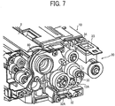
- the developer driving part 30 is covered by a duct 36 of the driving part, and the gears are covered by the driving part duct 36. (See FIGS. 4 to 7 .) Air is blown into the developer driving part 30 covered by the driving part duct 36 to cool the apparatus.
- the developer driving part 30 further includes an air inlet 37 and an air outlet 38 formed on the driving part duct 36.
- the driving part duct 36 is formed on the developing device 10 and not on the body of the image forming apparatus 1, and a shaft 32A of the idler gear 32 is engaged with the driving part duct 36 and is held therein.
- FIG. 8 shows a schematic view of an embodiment of the present invention, a right side of which is a front side of the body of the image forming apparatus 1 and a left side of which is a backside.
- a blast fan 40 an airflow generating means, is disposed at the front side of the body of the image forming apparatus 1.
- the blast fan 40 is connected to the air inlet 37 of the developer driving part 30 via a developer case surface duct 41 disposed along the surface of the developer case 22.
- the developer case surface duct 41 is a linear duct extending from front to backside of the body of the image forming apparatus 1 along the case surface of the developing device 10.
- the blast fan 40 is operated, an airflow C flowing from front to back sides of the image forming apparatus body passes through the duct 41.
- the developer case surface duct 41 may be implemented as a passage defined by the developer case 22 and the guide rail 21, thereby eliminating the cost of providing a duct.
- the air blasted from the air inlet 37 to the driving part duct 36 via the developer case surface duct 41 becomes an airflow D as illustrated in FIGS. 8 to 12 , and while cooling the shaft 12A of the agitation screw 12, the shaft 11A of the developing roller 11, and various gears, is discharged from the air outlet 38 to outside the driving part duct 36.
- the discharged airflow becomes exhaust air E.
- the air outlet 38 of the driving part duct 36 is connected to an air exhaust duct 42 disposed on the body of the image forming apparatus 1 as illustrated in FIG. 11 and exhaust air E discharged from the air outlet 38 of the driving part duct 36 flows as shown by an arrow in the figure and is exhausted from an air exhaust part 52 to outside the apparatus.
- the air exhaust part 52 communicates with air exhaust ducts 42Y, 42M, 42C, and 42K of the respective image forming units 20Y, 20M, 20C, and 20K and all exhaust ventilation is performed by a single exhaust fan 43.
- the exhaust fan 43 is configured to exhaust air from the image forming units 20Y, 20M, 20C, and 20K.
- the developer inside the developing device 10 is heated by friction between the developing doctor blade and the developing roller and friction of the ingredients of the developer itself. Further, as illustrated in FIG. 8 , temperature of the developer increases by H1: heat from the drive unit 50 transmitted to the input gear 31 of the developing device 10, H2: heat caused by a friction between an interior surface of the input gear 31 and a shaft 51 of the drive unit 50, H3: friction heat of the connection surface of gears such as input gear 31, idler gears 32 and 34, and gears 33 and 35, and H4: friction heat of the shaft bearings of such as the developing roller 11 and the agitation screw 12.
- H1 heat from the drive unit 50 transmitted to the input gear 31 of the developing device 10
- H2 heat caused by a friction between an interior surface of the input gear 31 and a shaft 51 of the drive unit 50
- H3 friction heat of the connection surface of gears such as input gear 31, idler gears 32 and 34, and gears 33 and 35
- H4 friction heat of the shaft bearings of such as the developing roller 11 and the
- the developer inside the developing device 10 is cooled according to the embodiment of the present invention by circulating the air as in the airflow C passing through the developer case surface duct 41 along the surface of the developer case 22 and by absorbing the heat from the surface of the developer case 22. Further, the airflow C is bent flexibly to be introduced into the driving part duct 36 from the air inlet 37 to become the airflow D and strike the drive unit 50, the input gear 31 and a shaft 51 of the drive unit 50, the input gear 31, idler gears 32 and 34, and gears 33 and 35, and the shaft bearings of such parts as the developing roller 11 and the agitation screw 12, thereby directly cooling driving systems generating heat (HI to H4) causing the temperature of the developer to rise.
- HI to H4 directly cooling driving systems generating heat
- the developer inside the developing device 10 is cooled by a series of winds formed by the blast fan 40 and the exhaust fan 43, and the driving system of the developing device 10 as a cause of the temperature rise is cooled.
- the heating of the developer can be efficiently reduced using an uncomplicated structure.
- the airflow generating means can be embodied by either the blast fan 40 or the exhaust fan 43 that can generate a flow of air.
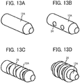
- the cooling efficiency can be improved by increasing a surface area of the shaft of various gears, the shaft 11A of the developing roller 11, and the shaft 12A of the agitation screw 12 inside the driving part duct 36 to get more airflow.
- the shaft 12A of the agitation screw 12 is elongated so as to have a larger surface area.
- the shaft 12A of the agitation screw 12 includes a through hole 24 so as to have a larger surface area.
- the shaft 12A of the agitation screw 12 includes grooves 25 along a circumference thereof so as to have a larger surface area.
- the shaft 12A of the agitation screw 12 includes fins 26 so as to have a larger surface area.
- the surface area of the shaft 12A of the agitation screw 12 is increased so that the cooling efficiency can be improved; however, the cooling efficiency can be further improved by increasing the surface area of the shaft of the various gears and the shaft of the developing roller 11.
- a cooling unit to cool the developing device 10 has been described.
- the cooling target is not limited to a developing device but is also applicable to the fixing device and the transfer device.
Landscapes
- Physics & Mathematics (AREA)
- Engineering & Computer Science (AREA)
- General Physics & Mathematics (AREA)
- Environmental Sciences (AREA)
- Ecology (AREA)
- Environmental & Geological Engineering (AREA)
- Life Sciences & Earth Sciences (AREA)
- Biodiversity & Conservation Biology (AREA)
- Atmospheric Sciences (AREA)
- Computer Vision & Pattern Recognition (AREA)
- Dry Development In Electrophotography (AREA)
- Control Or Security For Electrophotography (AREA)
- Electrophotography Configuration And Component (AREA)
Claims (5)
- Bilderzeugungsvorrichtung, umfassend:ein eingebautes Rotationsantriebselement (11, 12) einschließlich einer Welle;eine Entwicklungsvorrichtung (10) einschließlich eines Gehäuses und des eingebauten Rotationsantriebselements (11, 12), und die abnehmbar an einem Bilderzeugungsvorrichtungskörper (1) befestigt sein kann;ein Entwicklerantriebsteil (30), um das eingebaute Rotationsantriebselement (11, 12), das an einem Ende in einer Wellenrichtung des Rotationsantriebselements (11, 12) angeordnet ist, anzutreiben;einen Antriebsteilkanal (36), der den Entwicklerantriebsteil (30) umhüllt;einen Entwicklergehäuseoberflächenkanal (41), der entlang einer Oberfläche parallel zu der Wellenrichtung des Rotationsantriebselements (11, 12) gebildet ist; undein Luftstromerzeugungsmittel (40 oder 43), um Luft entweder von dem Antriebsteilkanal (36) oder dem Entwicklergehäuseoberflächenkanal (41) zu blasen.
- Bilderzeugungsvorrichtung nach Anspruch 1, wobei der Antriebsteilkanal (36) konfiguriert ist, um zuzulassen, dass Luft, die stromaufwärts verwendet wird, um das Entwicklungsgehäuse (22) zu kühlen, und die durch den Entwicklergehäuseoberflächenkanal (41) verläuft, durch den Antriebsteilkanal (36) strömt.
- Bilderzeugungsvorrichtung nach Anspruch 1, wobei die Welle des Rotationsantriebselements (11, 12), das in die Entwicklungsvorrichtung (10) eingebaut ist, eine Größe hat, um einen Oberflächenbereich davon in dem Entwicklungsteilkanal (36) zu erhöhen.
- Bilderzeugungsvorrichtung nach Anspruch 1, wobei der Antriebsteilkanal (36) aus einem Material gebildet ist, das eine Wärmeleitfähigkeit hat, die höher als die des Gehäuses der Entwicklungsvorrichtung (10) ist.
- Bilderzeugungsvorrichtung nach Anspruch 1, ferner umfassend:eine Führungsschiene (21), die konfiguriert ist, um die Entwicklungsvorrichtung (10) zu führen, wenn die Entwicklungsvorrichtung (10) an dem Bilderzeugungsvorrichtungskörper (1) befestigt und davon entfernt wird,wobei der Entwicklergehäuseoberflächenkanal (41) durch die Führungsschiene (21) und die Entwicklungsvorrichtung (10) definiert ist.
Applications Claiming Priority (2)
| Application Number | Priority Date | Filing Date | Title |
|---|---|---|---|
| JP2011192693 | 2011-09-05 | ||
| JP2012120630A JP2013068930A (ja) | 2011-09-05 | 2012-05-28 | 画像形成装置 |
Publications (3)
| Publication Number | Publication Date |
|---|---|
| EP2565724A2 EP2565724A2 (de) | 2013-03-06 |
| EP2565724A3 EP2565724A3 (de) | 2017-10-04 |
| EP2565724B1 true EP2565724B1 (de) | 2019-10-02 |
Family
ID=47048953
Family Applications (1)
| Application Number | Title | Priority Date | Filing Date |
|---|---|---|---|
| EP12181433.9A Active EP2565724B1 (de) | 2011-09-05 | 2012-08-23 | Bilderzeugungsvorrichtung |
Country Status (4)
| Country | Link |
|---|---|
| US (1) | US9158274B2 (de) |
| EP (1) | EP2565724B1 (de) |
| JP (1) | JP2013068930A (de) |
| CN (1) | CN102998929A (de) |
Families Citing this family (11)
| Publication number | Priority date | Publication date | Assignee | Title |
|---|---|---|---|---|
| JP6212911B2 (ja) | 2012-05-17 | 2017-10-18 | 株式会社リコー | 状態判定装置、画像処理装置、状態判定方法及び状態判定プログラム |
| JP6095378B2 (ja) * | 2013-01-23 | 2017-03-15 | キヤノン株式会社 | 画像形成装置 |
| US9170561B2 (en) * | 2013-01-25 | 2015-10-27 | Ricoh Company, Ltd. | Cooling device and image forming apparatus incorporating same |
| JP6225794B2 (ja) * | 2013-08-16 | 2017-11-08 | 富士ゼロックス株式会社 | 現像装置及び画像形成装置 |
| JP6668613B2 (ja) * | 2015-05-21 | 2020-03-18 | 富士ゼロックス株式会社 | 画像形成装置 |
| JP6394550B2 (ja) * | 2015-09-29 | 2018-09-26 | 京セラドキュメントソリューションズ株式会社 | 画像形成装置 |
| US10073413B2 (en) * | 2016-09-02 | 2018-09-11 | Fuji Xerox Co., Ltd. | Image forming apparatus with internal airflow |
| CN109960129A (zh) * | 2017-12-25 | 2019-07-02 | 柯尼卡美能达办公系统研发(无锡)有限公司 | 图像形成装置 |
| JP7621839B2 (ja) * | 2020-04-22 | 2025-01-27 | キヤノン株式会社 | 画像形成装置 |
| JP7523749B2 (ja) * | 2020-09-23 | 2024-07-29 | 株式会社リコー | 画像形成装置 |
| JP2023031208A (ja) * | 2021-08-23 | 2023-03-08 | 富士フイルムビジネスイノベーション株式会社 | 画像形成装置 |
Family Cites Families (29)
| Publication number | Priority date | Publication date | Assignee | Title |
|---|---|---|---|---|
| JP3472167B2 (ja) * | 1998-11-30 | 2003-12-02 | キヤノン株式会社 | 画像形成装置 |
| JP2003057927A (ja) | 2001-08-14 | 2003-02-28 | Canon Inc | 現像装置及びこれを備えるプロセスカートリッジ並びに画像形成装置 |
| JP2004093708A (ja) * | 2002-08-30 | 2004-03-25 | Brother Ind Ltd | 画像形成装置 |
| JP4247095B2 (ja) | 2003-11-06 | 2009-04-02 | 株式会社リコー | 現像装置・画像形成装置 |
| KR100520510B1 (ko) * | 2003-11-22 | 2005-10-11 | 삼성전자주식회사 | 전자사진방식 화상형성장치의 현상장치 |
| JP2006145727A (ja) | 2004-11-18 | 2006-06-08 | Kyocera Mita Corp | 冷却装置及びこれを搭載した画像形成装置 |
| JP4647323B2 (ja) * | 2005-01-31 | 2011-03-09 | 京セラミタ株式会社 | 冷却構造およびこの冷却構造を備えた画像形成装置 |
| JP4627219B2 (ja) * | 2005-06-03 | 2011-02-09 | シャープ株式会社 | 吸排気システム |
| JP2007086629A (ja) * | 2005-09-26 | 2007-04-05 | Brother Ind Ltd | 画像形成装置 |
| CN101145024A (zh) | 2006-09-12 | 2008-03-19 | 株式会社理光 | 处理盒和成像设备 |
| JP2008096944A (ja) * | 2006-09-12 | 2008-04-24 | Ricoh Co Ltd | プロセスカートリッジ及び画像形成装置 |
| JP5223275B2 (ja) | 2007-03-05 | 2013-06-26 | 株式会社リコー | 画像形成装置 |
| JP4964012B2 (ja) * | 2007-04-18 | 2012-06-27 | 株式会社リコー | 駆動装置、画像形成装置 |
| JP4871807B2 (ja) | 2007-05-29 | 2012-02-08 | 株式会社リコー | 画像形成装置 |
| JP2009053312A (ja) * | 2007-08-24 | 2009-03-12 | Konica Minolta Business Technologies Inc | 画像形成装置 |
| JP5182622B2 (ja) * | 2008-05-19 | 2013-04-17 | 株式会社リコー | 画像形成装置、画像形成装置の制御方法 |
| JP5222629B2 (ja) * | 2008-05-30 | 2013-06-26 | 京セラドキュメントソリューションズ株式会社 | 現像装置 |
| JP5252273B2 (ja) | 2008-05-30 | 2013-07-31 | 株式会社リコー | 現像装置及び画像形成装置 |
| JP2010061056A (ja) * | 2008-09-08 | 2010-03-18 | Ricoh Co Ltd | 画像形成装置 |
| US8150292B2 (en) * | 2008-09-30 | 2012-04-03 | Kyocera Mita Corporation | Developing unit and image forming apparatus comprising same |
| JP4353541B1 (ja) * | 2008-10-17 | 2009-10-28 | キヤノン株式会社 | 電子写真画像形成装置 |
| JP5559948B2 (ja) | 2010-03-12 | 2014-07-23 | Hoya株式会社 | 多層反射膜付基板の製造方法および反射型マスクブランクの製造方法 |
| JP5268990B2 (ja) * | 2010-05-11 | 2013-08-21 | シャープ株式会社 | 画像形成装置 |
| JP5062297B2 (ja) * | 2010-06-11 | 2012-10-31 | コニカミノルタビジネステクノロジーズ株式会社 | 現像剤収容装置および画像形成装置 |
| CN102289171A (zh) * | 2010-06-17 | 2011-12-21 | 京瓷美达株式会社 | 显影装置及具备该显影装置的图像形成装置 |
| JP5932282B2 (ja) * | 2010-10-29 | 2016-06-08 | キヤノン株式会社 | 画像形成装置 |
| JP5392853B2 (ja) | 2010-12-07 | 2014-01-22 | 株式会社大都技研 | 遊技台 |
| JP5825062B2 (ja) * | 2011-02-28 | 2015-12-02 | ブラザー工業株式会社 | 画像形成装置 |
| JP5904774B2 (ja) * | 2011-12-06 | 2016-04-20 | キヤノン株式会社 | 画像形成装置 |
-
2012
- 2012-05-28 JP JP2012120630A patent/JP2013068930A/ja active Pending
- 2012-08-23 EP EP12181433.9A patent/EP2565724B1/de active Active
- 2012-08-30 US US13/599,247 patent/US9158274B2/en active Active
- 2012-09-05 CN CN201210325360XA patent/CN102998929A/zh active Pending
Non-Patent Citations (1)
| Title |
|---|
| None * |
Also Published As
| Publication number | Publication date |
|---|---|
| US9158274B2 (en) | 2015-10-13 |
| US20130058676A1 (en) | 2013-03-07 |
| CN102998929A (zh) | 2013-03-27 |
| EP2565724A3 (de) | 2017-10-04 |
| EP2565724A2 (de) | 2013-03-06 |
| JP2013068930A (ja) | 2013-04-18 |
Similar Documents
| Publication | Publication Date | Title |
|---|---|---|
| EP2565724B1 (de) | Bilderzeugungsvorrichtung | |
| US8417142B2 (en) | Image forming apparatus having developing device cooling mechanism, and control method therefor | |
| US9170561B2 (en) | Cooling device and image forming apparatus incorporating same | |
| JP2014106284A (ja) | 冷却システム、及び画像形成装置 | |
| US8818230B2 (en) | Image forming apparatus | |
| JP5239498B2 (ja) | 無端状部材駆動装置および画像形成装置 | |
| JP2016126197A (ja) | 現像装置及び画像形成装置 | |
| JP2015028563A (ja) | 画像形成装置 | |
| JP5424539B2 (ja) | 画像形成装置 | |
| JP5857631B2 (ja) | 画像形成装置 | |
| JP5219396B2 (ja) | 画像形成装置 | |
| JP5135999B2 (ja) | 画像形成装置 | |
| JP2011154316A (ja) | 画像形成装置 | |
| JP5817375B2 (ja) | 画像形成装置 | |
| JP5877414B2 (ja) | 排気システムおよび画像形成装置 | |
| US8886078B2 (en) | Image forming apparatus | |
| JP2015158580A (ja) | 排気処理ユニットおよび画像形成装置 | |
| JP4174119B2 (ja) | 画像形成装置 | |
| JP5420048B2 (ja) | 画像形成装置 | |
| JP2009198847A (ja) | 画像形成装置 | |
| JP5463730B2 (ja) | 画像形成装置 | |
| US11960223B2 (en) | Image forming apparatus having fixation unit and ducts for cooling | |
| JP5822093B2 (ja) | 画像形成装置 | |
| JP2012141645A (ja) | 画像形成装置 | |
| JP4983763B2 (ja) | 画像形成装置 |
Legal Events
| Date | Code | Title | Description |
|---|---|---|---|
| PUAI | Public reference made under article 153(3) epc to a published international application that has entered the european phase |
Free format text: ORIGINAL CODE: 0009012 |
|
| 17P | Request for examination filed |
Effective date: 20120823 |
|
| AK | Designated contracting states |
Kind code of ref document: A2 Designated state(s): AL AT BE BG CH CY CZ DE DK EE ES FI FR GB GR HR HU IE IS IT LI LT LU LV MC MK MT NL NO PL PT RO RS SE SI SK SM TR |
|
| AX | Request for extension of the european patent |
Extension state: BA ME |
|
| PUAL | Search report despatched |
Free format text: ORIGINAL CODE: 0009013 |
|
| AK | Designated contracting states |
Kind code of ref document: A3 Designated state(s): AL AT BE BG CH CY CZ DE DK EE ES FI FR GB GR HR HU IE IS IT LI LT LU LV MC MK MT NL NO PL PT RO RS SE SI SK SM TR |
|
| AX | Request for extension of the european patent |
Extension state: BA ME |
|
| RIC1 | Information provided on ipc code assigned before grant |
Ipc: G03G 15/08 20060101ALI20170830BHEP Ipc: G03G 21/20 20060101AFI20170830BHEP |
|
| GRAP | Despatch of communication of intention to grant a patent |
Free format text: ORIGINAL CODE: EPIDOSNIGR1 |
|
| STAA | Information on the status of an ep patent application or granted ep patent |
Free format text: STATUS: GRANT OF PATENT IS INTENDED |
|
| INTG | Intention to grant announced |
Effective date: 20190418 |
|
| RIN1 | Information on inventor provided before grant (corrected) |
Inventor name: SATO, YUKI |
|
| GRAS | Grant fee paid |
Free format text: ORIGINAL CODE: EPIDOSNIGR3 |
|
| GRAA | (expected) grant |
Free format text: ORIGINAL CODE: 0009210 |
|
| STAA | Information on the status of an ep patent application or granted ep patent |
Free format text: STATUS: THE PATENT HAS BEEN GRANTED |
|
| AK | Designated contracting states |
Kind code of ref document: B1 Designated state(s): AL AT BE BG CH CY CZ DE DK EE ES FI FR GB GR HR HU IE IS IT LI LT LU LV MC MK MT NL NO PL PT RO RS SE SI SK SM TR |
|
| REG | Reference to a national code |
Ref country code: GB Ref legal event code: FG4D |
|
| REG | Reference to a national code |
Ref country code: AT Ref legal event code: REF Ref document number: 1186875 Country of ref document: AT Kind code of ref document: T Effective date: 20191015 Ref country code: CH Ref legal event code: EP |
|
| REG | Reference to a national code |
Ref country code: DE Ref legal event code: R096 Ref document number: 602012064462 Country of ref document: DE |
|
| REG | Reference to a national code |
Ref country code: IE Ref legal event code: FG4D |
|
| REG | Reference to a national code |
Ref country code: NL Ref legal event code: FP |
|
| REG | Reference to a national code |
Ref country code: LT Ref legal event code: MG4D |
|
| REG | Reference to a national code |
Ref country code: AT Ref legal event code: MK05 Ref document number: 1186875 Country of ref document: AT Kind code of ref document: T Effective date: 20191002 |
|
| PG25 | Lapsed in a contracting state [announced via postgrant information from national office to epo] |
Ref country code: BG Free format text: LAPSE BECAUSE OF FAILURE TO SUBMIT A TRANSLATION OF THE DESCRIPTION OR TO PAY THE FEE WITHIN THE PRESCRIBED TIME-LIMIT Effective date: 20200102 Ref country code: FI Free format text: LAPSE BECAUSE OF FAILURE TO SUBMIT A TRANSLATION OF THE DESCRIPTION OR TO PAY THE FEE WITHIN THE PRESCRIBED TIME-LIMIT Effective date: 20191002 Ref country code: PT Free format text: LAPSE BECAUSE OF FAILURE TO SUBMIT A TRANSLATION OF THE DESCRIPTION OR TO PAY THE FEE WITHIN THE PRESCRIBED TIME-LIMIT Effective date: 20200203 Ref country code: SE Free format text: LAPSE BECAUSE OF FAILURE TO SUBMIT A TRANSLATION OF THE DESCRIPTION OR TO PAY THE FEE WITHIN THE PRESCRIBED TIME-LIMIT Effective date: 20191002 Ref country code: LV Free format text: LAPSE BECAUSE OF FAILURE TO SUBMIT A TRANSLATION OF THE DESCRIPTION OR TO PAY THE FEE WITHIN THE PRESCRIBED TIME-LIMIT Effective date: 20191002 Ref country code: ES Free format text: LAPSE BECAUSE OF FAILURE TO SUBMIT A TRANSLATION OF THE DESCRIPTION OR TO PAY THE FEE WITHIN THE PRESCRIBED TIME-LIMIT Effective date: 20191002 Ref country code: NO Free format text: LAPSE BECAUSE OF FAILURE TO SUBMIT A TRANSLATION OF THE DESCRIPTION OR TO PAY THE FEE WITHIN THE PRESCRIBED TIME-LIMIT Effective date: 20200102 Ref country code: GR Free format text: LAPSE BECAUSE OF FAILURE TO SUBMIT A TRANSLATION OF THE DESCRIPTION OR TO PAY THE FEE WITHIN THE PRESCRIBED TIME-LIMIT Effective date: 20200103 Ref country code: PL Free format text: LAPSE BECAUSE OF FAILURE TO SUBMIT A TRANSLATION OF THE DESCRIPTION OR TO PAY THE FEE WITHIN THE PRESCRIBED TIME-LIMIT Effective date: 20191002 Ref country code: AT Free format text: LAPSE BECAUSE OF FAILURE TO SUBMIT A TRANSLATION OF THE DESCRIPTION OR TO PAY THE FEE WITHIN THE PRESCRIBED TIME-LIMIT Effective date: 20191002 Ref country code: LT Free format text: LAPSE BECAUSE OF FAILURE TO SUBMIT A TRANSLATION OF THE DESCRIPTION OR TO PAY THE FEE WITHIN THE PRESCRIBED TIME-LIMIT Effective date: 20191002 |
|
| PG25 | Lapsed in a contracting state [announced via postgrant information from national office to epo] |
Ref country code: CZ Free format text: LAPSE BECAUSE OF FAILURE TO SUBMIT A TRANSLATION OF THE DESCRIPTION OR TO PAY THE FEE WITHIN THE PRESCRIBED TIME-LIMIT Effective date: 20191002 Ref country code: HR Free format text: LAPSE BECAUSE OF FAILURE TO SUBMIT A TRANSLATION OF THE DESCRIPTION OR TO PAY THE FEE WITHIN THE PRESCRIBED TIME-LIMIT Effective date: 20191002 Ref country code: RS Free format text: LAPSE BECAUSE OF FAILURE TO SUBMIT A TRANSLATION OF THE DESCRIPTION OR TO PAY THE FEE WITHIN THE PRESCRIBED TIME-LIMIT Effective date: 20191002 Ref country code: IS Free format text: LAPSE BECAUSE OF FAILURE TO SUBMIT A TRANSLATION OF THE DESCRIPTION OR TO PAY THE FEE WITHIN THE PRESCRIBED TIME-LIMIT Effective date: 20200224 |
|
| PG25 | Lapsed in a contracting state [announced via postgrant information from national office to epo] |
Ref country code: AL Free format text: LAPSE BECAUSE OF FAILURE TO SUBMIT A TRANSLATION OF THE DESCRIPTION OR TO PAY THE FEE WITHIN THE PRESCRIBED TIME-LIMIT Effective date: 20191002 |
|
| REG | Reference to a national code |
Ref country code: DE Ref legal event code: R097 Ref document number: 602012064462 Country of ref document: DE |
|
| PG2D | Information on lapse in contracting state deleted |
Ref country code: IS |
|
| PG25 | Lapsed in a contracting state [announced via postgrant information from national office to epo] |
Ref country code: IS Free format text: LAPSE BECAUSE OF FAILURE TO SUBMIT A TRANSLATION OF THE DESCRIPTION OR TO PAY THE FEE WITHIN THE PRESCRIBED TIME-LIMIT Effective date: 20200202 Ref country code: RO Free format text: LAPSE BECAUSE OF FAILURE TO SUBMIT A TRANSLATION OF THE DESCRIPTION OR TO PAY THE FEE WITHIN THE PRESCRIBED TIME-LIMIT Effective date: 20191002 Ref country code: DK Free format text: LAPSE BECAUSE OF FAILURE TO SUBMIT A TRANSLATION OF THE DESCRIPTION OR TO PAY THE FEE WITHIN THE PRESCRIBED TIME-LIMIT Effective date: 20191002 Ref country code: EE Free format text: LAPSE BECAUSE OF FAILURE TO SUBMIT A TRANSLATION OF THE DESCRIPTION OR TO PAY THE FEE WITHIN THE PRESCRIBED TIME-LIMIT Effective date: 20191002 |
|
| PLBE | No opposition filed within time limit |
Free format text: ORIGINAL CODE: 0009261 |
|
| STAA | Information on the status of an ep patent application or granted ep patent |
Free format text: STATUS: NO OPPOSITION FILED WITHIN TIME LIMIT |
|
| PG25 | Lapsed in a contracting state [announced via postgrant information from national office to epo] |
Ref country code: IT Free format text: LAPSE BECAUSE OF FAILURE TO SUBMIT A TRANSLATION OF THE DESCRIPTION OR TO PAY THE FEE WITHIN THE PRESCRIBED TIME-LIMIT Effective date: 20191002 Ref country code: SM Free format text: LAPSE BECAUSE OF FAILURE TO SUBMIT A TRANSLATION OF THE DESCRIPTION OR TO PAY THE FEE WITHIN THE PRESCRIBED TIME-LIMIT Effective date: 20191002 Ref country code: SK Free format text: LAPSE BECAUSE OF FAILURE TO SUBMIT A TRANSLATION OF THE DESCRIPTION OR TO PAY THE FEE WITHIN THE PRESCRIBED TIME-LIMIT Effective date: 20191002 |
|
| 26N | No opposition filed |
Effective date: 20200703 |
|
| PG25 | Lapsed in a contracting state [announced via postgrant information from national office to epo] |
Ref country code: SI Free format text: LAPSE BECAUSE OF FAILURE TO SUBMIT A TRANSLATION OF THE DESCRIPTION OR TO PAY THE FEE WITHIN THE PRESCRIBED TIME-LIMIT Effective date: 20191002 |
|
| PG25 | Lapsed in a contracting state [announced via postgrant information from national office to epo] |
Ref country code: MC Free format text: LAPSE BECAUSE OF FAILURE TO SUBMIT A TRANSLATION OF THE DESCRIPTION OR TO PAY THE FEE WITHIN THE PRESCRIBED TIME-LIMIT Effective date: 20191002 |
|
| REG | Reference to a national code |
Ref country code: CH Ref legal event code: PL |
|
| PG25 | Lapsed in a contracting state [announced via postgrant information from national office to epo] |
Ref country code: LU Free format text: LAPSE BECAUSE OF NON-PAYMENT OF DUE FEES Effective date: 20200823 Ref country code: LI Free format text: LAPSE BECAUSE OF NON-PAYMENT OF DUE FEES Effective date: 20200831 Ref country code: CH Free format text: LAPSE BECAUSE OF NON-PAYMENT OF DUE FEES Effective date: 20200831 |
|
| REG | Reference to a national code |
Ref country code: BE Ref legal event code: MM Effective date: 20200831 |
|
| PG25 | Lapsed in a contracting state [announced via postgrant information from national office to epo] |
Ref country code: BE Free format text: LAPSE BECAUSE OF NON-PAYMENT OF DUE FEES Effective date: 20200831 Ref country code: IE Free format text: LAPSE BECAUSE OF NON-PAYMENT OF DUE FEES Effective date: 20200823 |
|
| PG25 | Lapsed in a contracting state [announced via postgrant information from national office to epo] |
Ref country code: TR Free format text: LAPSE BECAUSE OF FAILURE TO SUBMIT A TRANSLATION OF THE DESCRIPTION OR TO PAY THE FEE WITHIN THE PRESCRIBED TIME-LIMIT Effective date: 20191002 Ref country code: MT Free format text: LAPSE BECAUSE OF FAILURE TO SUBMIT A TRANSLATION OF THE DESCRIPTION OR TO PAY THE FEE WITHIN THE PRESCRIBED TIME-LIMIT Effective date: 20191002 Ref country code: CY Free format text: LAPSE BECAUSE OF FAILURE TO SUBMIT A TRANSLATION OF THE DESCRIPTION OR TO PAY THE FEE WITHIN THE PRESCRIBED TIME-LIMIT Effective date: 20191002 |
|
| PG25 | Lapsed in a contracting state [announced via postgrant information from national office to epo] |
Ref country code: MK Free format text: LAPSE BECAUSE OF FAILURE TO SUBMIT A TRANSLATION OF THE DESCRIPTION OR TO PAY THE FEE WITHIN THE PRESCRIBED TIME-LIMIT Effective date: 20191002 |
|
| P01 | Opt-out of the competence of the unified patent court (upc) registered |
Effective date: 20230522 |
|
| PGFP | Annual fee paid to national office [announced via postgrant information from national office to epo] |
Ref country code: NL Payment date: 20250821 Year of fee payment: 14 |
|
| PGFP | Annual fee paid to national office [announced via postgrant information from national office to epo] |
Ref country code: DE Payment date: 20250820 Year of fee payment: 14 |
|
| PGFP | Annual fee paid to national office [announced via postgrant information from national office to epo] |
Ref country code: GB Payment date: 20250821 Year of fee payment: 14 |
|
| PGFP | Annual fee paid to national office [announced via postgrant information from national office to epo] |
Ref country code: FR Payment date: 20250829 Year of fee payment: 14 |