EP2565728A1 - Autonomer Steuermechnismus für ein Uhrenteil - Google Patents
Autonomer Steuermechnismus für ein Uhrenteil Download PDFInfo
- Publication number
- EP2565728A1 EP2565728A1 EP11179180A EP11179180A EP2565728A1 EP 2565728 A1 EP2565728 A1 EP 2565728A1 EP 11179180 A EP11179180 A EP 11179180A EP 11179180 A EP11179180 A EP 11179180A EP 2565728 A1 EP2565728 A1 EP 2565728A1
- Authority
- EP
- European Patent Office
- Prior art keywords
- control
- wheel
- main bridge
- drive means
- rod
- Prior art date
- Legal status (The legal status is an assumption and is not a legal conclusion. Google has not performed a legal analysis and makes no representation as to the accuracy of the status listed.)
- Granted
Links
Images






Classifications
-
- G—PHYSICS
- G04—HOROLOGY
- G04B—MECHANICALLY-DRIVEN CLOCKS OR WATCHES; MECHANICAL PARTS OF CLOCKS OR WATCHES IN GENERAL; TIME PIECES USING THE POSITION OF THE SUN, MOON OR STARS
- G04B27/00—Mechanical devices for setting the time indicating means
- G04B27/02—Mechanical devices for setting the time indicating means by making use of the winding means
- G04B27/04—Mechanical devices for setting the time indicating means by making use of the winding means with clutch wheel
-
- G—PHYSICS
- G04—HOROLOGY
- G04B—MECHANICALLY-DRIVEN CLOCKS OR WATCHES; MECHANICAL PARTS OF CLOCKS OR WATCHES IN GENERAL; TIME PIECES USING THE POSITION OF THE SUN, MOON OR STARS
- G04B27/00—Mechanical devices for setting the time indicating means
- G04B27/001—Internal gear therefor, e.g. for setting the second hand or for setting several clockworks
Definitions
- the invention relates to an autonomous control mechanism for a watch movement or a timepiece, comprising at least one selection and / or control means, or at least one control rod, movable relative to a main bridge between a plurality of stable rod positions, for the pivotal drive control, in each said stable rod position, of a single control wheel from among a plurality of control wheels included in said mechanism. watchmaking including at least one such autonomous control mechanism.
- the invention also relates to a timepiece comprising such an autonomous control mechanism, or comprising such a clockwork movement.
- the invention relates to the field of watchmaking.
- winding mechanism is usually related to a particular assembly sequence, which generally does not allow to perform the exchange of the rod, once the movement nested. This is not compatible with a modular design, in which one wishes to be able to use a module or a particular template for several different products.
- the invention proposes to develop an autonomous control mechanism, in particular and without limitation a winding mechanism, which constitutes an independent module and which lends itself to a robotic assembly.
- the developed mechanism contains the least possible component, and must be reliable and robust. It must, again, lend itself easily to after-sales operations, for example the exchange of a rod, without dislocation of the complete movement.
- the invention relates to an autonomous control mechanism for a watch movement or timepiece, comprising at least one selection and / or control means, or at least one control rod, movable relative to a main bridge between a plurality of stable rod positions, for the pivot drive control, in each said stable rod position, of a single control wheel from among a plurality of control wheels included in said mechanism, characterized in that it comprises, on a first side of said main bridge, at least a first control wheel or a first control drive means, and, on a second side of said main bridge opposite said first side, at least a second a control wheel or a second control drive means, and in that said rod controls the positioning of a pull tab applied to said first side or to said second side and movable relative to a boss a pin included in said main bridge, in a stable drawbar position associated with each said stable rod position, wherein said stable zipper position any movement applied to said control rod by the user causes the pivoting movement, or a single said first control train or first control drive means, or a single
- said control rod comprises guiding means which cooperate with complementary guiding means which comprises a sliding pinion mounted on said control rod, so as to allow a translation of said sliding pinion relative to said control rod in a longitudinal direction in which is movable said control rod relative to said main bridge, and so as to slave said pinion pivotally with said control rod relative to a pivot axis about which said control rod is arranged to pivot
- said sliding pinion comprises a first drive means arranged to drive a said first control train or control drive means
- said sliding pinion further comprises a second drive means arranged to drive a said second control train or second control drive means.
- said sliding pinion is in one piece and comprises a first toothing arranged to cooperate with a first drive gear of a said first control gear or first control drive means, and comprises a second toothing arranged to cooperate with a second drive wheel drive of a said second control train or second control drive means.
- said autonomous control mechanism comprises, applied on said first side or on said second side of said main bridge opposite that which carries said pull tab, a rocker arranged to carry a second idler wheel arranged to cooperate with said second drive means for driving, according to the position of said latch, a single said second control train or second control drive means, from among a plurality of said second control gear or second gear means. command drive.
- said rocker is pivotally mounted on a boss or a pin that comprises said main bridge, and is pivotally driven under the effect of the displacement of said control rod in said longitudinal direction, directly or indirectly via said sliding pinion, and comprises an elastic arm whose free end comprises bearing surfaces arranged to cooperate in the locking position with a boss or a pin that includes said main bridge.
- said main bridge carries a first boss or pivot arranged to pivotally guide a first wheel that comprises one of said second control wheels or second control drive means, said first wheel being arranged to mesh with said second idler wheel in a first position of said flip-flop, and said main bridge carries a second boss or pivot arranged to pivotally guide a second wheel that includes one of said second control wheels or second control drive means, said second wheel being arranged to mesh with said second idle wheel in a second position of said flip-flop, and said flip-flop is interposed between said main bridge and said first wheel on the one hand, and said second wheel on the other hand.
- said main bridge comprises, on the side which carries said pull-tab, a stepped tenon for guiding a first idler wheel superimposed with respect to said pull-tab and arranged to cooperate with said first drive means.
- drive for driving, according to the position of said rocker, a single said first control train or first control drive means, said stepped stud having an almond profile to allow the positioning of said first idler wheel between two extreme positions, one in which said first idler gear is engaged with said first drive means and the other in which said first idler gear is unhooked from said first drive means.
- said main bridge carries a second boss or pivot arranged to pivotally guide a return wheel meshing with said first idler wheel, and plated on said main bridge.
- the invention also relates to a watch movement comprising at least one such autonomous control mechanism, characterized in that said movement comprises a plurality of mechanisms each arranged to cooperate with one of said first control wheel or first control drive means , or with one of said second control train or second control drive means.
- said mechanism comprises, on a first side of said main bridge, a first control train comprising a ratchet gear for a winding mechanism that includes said movement arranged to be actuated by a pivoting of said control rod in a first depressed position of said control rod, and, on a second side of said main bridge, two second control wheels, one having a first adjustment control wheel of a time setting mechanism comprising said movement arranged to be actuated by a pivoting of said control rod in a third position drawn from said control rod, and the other comprising a second control wheel for adjusting a mechanism date of said movement arranged to be actuated by a pivoting of said control rod in a second position drawn from said control rod.
- the invention also relates to a timepiece comprising such an autonomous control mechanism, or comprising such a clockwork movement.
- the invention relates to the field of watchmaking, and more particularly the field of watch movements.
- the object of the invention is to provide an autonomous control mechanism 100 complete and arranged to be directly mounted in cooperation with other components or subassemblies constituting a watch movement 1000 or a part of a watch. 2000 watchmaking, including a watch.
- This autonomous control mechanism 100 is designed to be entirely assembled apart from the rest of the movement or the piece, and to constitute a versatile module that can be used in different movements or different timepieces.
- the mechanism 100 can be used for a movement barrel winding control, for a winding drum winding control, for a ringing and / or wakeup selection and triggering control, for a control time zone, or, in general, for the control of other displays than the main display of the movement or the timepiece.
- the design of the mechanism 100 is oriented towards a great compactness, in particular as small a thickness as possible, and towards the assembly of all its components on either side of a main bridge 80, with the exception of a rod.
- control device 10 substantially parallel to the latter, and adapted to be mounted radially or substantially tangentially on the periphery of a timepiece. It is thus possible to equip the periphery of a timepiece, even of small size, with several mechanisms 100 according to the invention, each for the control of one or more particular functions.
- This design attaches to easy assembly of the components of the mechanism 100, preferably normally to the main deck 80, which facilitates the automation of the assembly, in particular in a robotic manner, which very significantly reduces the production costs.
- the components are particularly simple, come from stamping, bar turning or injection, and are themselves inexpensive.
- the assembly sequence of the components of the mechanism 100 is provided to directly ensure their correct positioning, and their maintenance, which allows any type of manipulation or overturning by a robotic installation without risk of maladjustment or loss of components.
- the mechanism 100 can thus be assembled finished.
- the design provides a great ease of assembly and disassembly of the control rod, to facilitate maintenance and after-sales.
- the autonomous control mechanism 100 for a watch movement or a timepiece comprises at least one selection and / or control means, or at least one control rod 10.
- the invention is here more particularly described with at least one such selection means and / or control, consisting of a control rod 10.
- This control rod 10 is movable relative to a main bridge 80 between a plurality of stable positions for pivotally controlling, in each stable rod position, a single control wheel from among a plurality of control wheels which the mechanism 100 comprises.
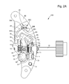
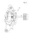
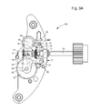
- figures 2 , 2A and 3 , 3A illustrate a first recessed position T1 of the rod in a conventional configuration where it is carried in this position winding a barrel; the figures 12 and 14 illustrate a first T2 traction position of the control rod 10, for example for setting a date, and the figures 13 and 15 illustrate a second traction position T3 of the control rod 10, for example for a setting time setting.
- the mechanism 100 with more control positions of the control rod 10: for example, for the mode selection of a striking mechanism, one can provide a position for each mode: small ring , big ring, minute repeater, alarm clock, silence; the associated commands may then consist of wakeup arm / disarm, grand arousal trigger, ringer remount, and the like commands.
- control rod 10 is illustrated here with a linear movement in a right longitudinal direction. But a circular motion, or other, is also imaginable without departing from the invention.
- control rod 10 may also consist of a rack cooperating with a pinion carrying a crown that can be manipulated by the user.
- the control mechanism 100 comprises, on a first side 81, said gear side, the main bridge 80, at least a first control wheel 810 or a first control drive means, for example a cam , a column wheel, a pulley, or the like.
- a first control wheel 810 or a first control drive means for example a cam , a column wheel, a pulley, or the like.
- the invention is more particularly described in a preferred embodiment, not limiting, including gear transmissions.
- the control mechanism 100 further comprises, on a second side 82, said dial side, the main bridge 80 opposite the first side 81, at least one second control wheel 820, or a second control drive means.
- the control rod 10 controls the positioning of a pull tab 20.
- This pull tab 20 is applied to the first side 81, here called “gear side”, or on the second side 82, here called “dial side”, and is movable in pivoting, by a bore 21 that it comprises, relative to a boss 210 or a pin that includes the main bridge 80, in a stable position of zipper associated with each stable rod position.
- the invention is illustrated in the figures with the pull tab 20 applied to the first side 81, said to be the gear side, as visible on the figures 2 , 5 , 12 and 13 .
- any movement applied to the control rod 10 by the user causes the pivoting movement, or of a single first control train 810 or first control drive means, or a single second control wheel 820 or second control drive means.
- the pull tab 20 comprises a flexible arm 24, one free end of which has oblique-tapered teeth, defining recesses called notches 25 or 125 to immobilize it in stable positions of pull relative to a boss 250 or a pin that the bridge comprises. main 80.
- the boss 250 is extended by a washer 251, driven and / or welded thereto, which provides the holding function of the elastic arm 24.
- the arm 24 is bent on the washer 251 when lifting the pull arm 22.
- the Figure 2A and the figure 5 show notches 25A, 25B, 25C, adapted for holding the pull tab for the depressed T1 position of the control rod 10 in the case of the figure 2 where the notch 25A cooperates with a pin 250 driven on the main deck 80, for the first position T2 pulled from the control rod 10 in the case of the figure 12 corresponding also to the figure 14 and where the notch 25B cooperates with the pin 250, and for the second position T3 pulled from the control rod 10 in the case of the figure 13 corresponding also to the figure 15 and where the notch 25C cooperates with the pin 250.
- This notch 25C is, in this particular case, constituted only by a slope at the end of the flexible arm 24.
- the pull tab 20 further comprises an oblong slot 26, arranged to cooperate, in a position of plating of the pull tab 20, with a boss 260 or a pin 126 that includes the main bridge 80.
- the control rod 10 conventionally comprises guide means, such as a square-section shaft or the like, which cooperate with complementary guide means, such as a female square, or dishes, or the like, which comprises a pinion runner 13 mounted on the control rod 10, so as to allow a translation of the sliding pinion 13 relative to the control rod 10 in a longitudinal direction in which the control rod 10 is movable relative to the main bridge 80, and so as to slave the sliding pinion 13 pivotally with the control rod 10 relative to a pivot axis about which the control rod 10 is arranged to rotate.
- guide means such as a square-section shaft or the like
- complementary guide means such as a female square, or dishes, or the like
- the figure 18 illustrates a pull tab 20, an outer side of the flexible arm 24 has notches 125A, 125B, 125C, which are disposed opposite the pivot boss 210 housed in the bore 21 of the pull tab 20, while in the variant of the figure 5 the notches 25A, 25B, 25C are disposed on the inner side of the arm 24 facing this pivot.
- This figure 18 corresponds to the depressed position T1 of the control rod 10, where the notch 125A cooperates with the pin 250 to ensure by itself the maintenance in this position 1. And the pin 126 integral with the plate is then distant from the edge of the light 26 a short distance d.
- this shock causes the pull tab 20, and is absorbed by the deformation of the flexible arm 24 forming spring, and the light 26 acts as a stroke limiter.
- the displacement of a sliding pinion 13 is taken up by an almond bearing that comprises a stepped pin 64 which will be presented later.
- the sliding pinion 13 further comprises a first drive means 14, which is arranged to drive a first control wheel 810, or first control drive means.
- the sliding pinion 13 further comprises a second drive means 15 arranged to drive a second control wheel 820, or second control drive means.
- the control rod 10 has a groove 11, as visible on the figure 3 , arranged to drive a first arm 22 that includes the pull tab 20, to bring it from one stable position of pull to another.
- the control rod 10 comprises a rod lock 19, for example in the form of a shoulder, which limits on one side the groove 11, and the support of the first pull arm 22 prohibits the extraction of the rod from command 10 in normal regime; according to the invention, the only possibility of extraction of the control rod 10, as will be explained later, is to act on the elasticity of this pull arm 22, and deform it away from the axis of the control rod 10 to allow the release thereof.
- the pull tab 20 further comprises a second arm 23, which is arranged to cooperate with a groove 16 that includes the sliding pinion 13 visible on the figure 14 , to move the sliding pinion 13 between a first position where the first drive means 14 cooperates with a first control gear 810 or first control drive means, and a second position where the second drive means 15 cooperates with a second control wheel 820 or second control drive means.
- the second drive means 15 does not does not cooperate with a second control wheel 820 or second control drive means
- the first drive means 14 does not cooperate with a first control gear 810 or first means of control. command drive
- the sliding pinion 13 is in one piece, and has a first toothing 14 arranged to cooperate with a first idler wheel 63, called a crown gear, for driving such a gear.
- the sliding pinion 13 comprises, in the same way, and at the opposite end of the first toothing 14, a second toothing 15 arranged to cooperate with a second idler wheel 36 driving a second control wheel 820 or second means command drive.
- the first idler wheel 63 and the second idler wheel 36 are located on two opposite sides of the main deck 80, in the thickness of which the control rod 10 and the sliding pinion 13 circulate. It is therefore clear that the sliding pinion 13 engages only with one of these two crazy wheels at a time.
- the meshing with each of the wheels is on two opposite sides of the main deck 80, with two opposite sets of teeth 14 and 15 of the sliding pinion 13.
- the first idler wheel 63 can mesh with the first toothing 14 of the sliding pinion 13, the first side 81, said gear side, of the main bridge 80, as visible on the figures 2 and 4 .
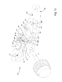
- the second idler wheel 36 can mesh with the second toothing 15 of the sliding pinion 13, the second side 82, said dial side, of the main bridge 80, as visible on the figure 11 .
- the first toothing 14 of the sliding pinion 13 is of larger diameter than the second toothing 15, their radius deviation is slightly greater than the thickness of the first idler wheel 63, so that the latter can pass through above the second toothing 15 of the sliding pinion 13 when the control rod 10 is in one of the traction positions T2 or T3
- This sliding pinion 13 can be executed by injection, metal, or high-strength plastic material.
- the main bridge 80 designed to be an injected part, in particular plastic, supports the maximum complexity, so that all other components are as simple as possible.
- This main bridge 80 has tenons or bosses of recovery of effort relative to a plate on which it is arranged to be assembled.
- the wheels and movable members pivoting relative to the main bridge 80 are preferably pivotally mounted on steel pivots, which are driven into this main bridge 80.
- the main deck 80 preferably comprises a cylindrical cradle 83 for receiving a cylindrical bearing surface of the sliding pinion 13.
- This cradle 83 also comprises a bore 84 serving as a housing for a stepped post 64 whose function will be detailed later.
- the autonomous control mechanism 100 comprises, applied on the first side 81 or the second side 82 of the main bridge 80 opposite the one carrying the pull tab 20, a latch 30, shown in FIG. figure 6 .
- This rocker 30 is arranged to carry a second idler wheel 36 arranged to cooperate with the second drive means 15, for driving, according to the position of the rocker 30, a single second control wheel 820 or second means d control drive, among a plurality of second control wheels 820 or second control drive means.
- the rocker 30 is pivotally mounted, at a bore 31 that it comprises, on a boss 310 or a pin that includes the main bridge 80.
- the rocker 30 is pivoted under the effect of the displacement of the rod. control 10 in the longitudinal direction, directly or indirectly via the sliding pinion 13.
- the latch 30 comprises an oblong slot 33, which cooperates with a stud 330 of the main bridge 80, which constitutes a travel limiter of the latch 30.
- the rocker 30 comprises a pivot supporting the second idler wheel 36, this pivot is preferably in the form of a stepped pin 32, a flange of which serves to maintain the recommended intermeshing distances with a first wheel 46 and with a second wheel 47, with which can alternately cooperate the second idler wheel 36.
- This pin 32 can be made by bar turning, it can also come deep drawing with the latch 30 itself.
- the main bridge 80 carries a first boss 460 or pivot, which is arranged to pivotally guide a first wheel 46 that includes one of the second control wheels 820 or second control drive means.
- This first wheel 46 is arranged to mesh with the second idler wheel 36 in a first position of the rocker 30.
- the main bridge 80 carries a second boss 470 or pivot, which is arranged to pivotally guide a second wheel 47 that includes one of the second control wheels 820 or second control drive means.
- This second wheel 46 is arranged to mesh with the second idler wheel 36 in a second position of the rocker 30.
- the rocker 30 is interposed between the main bridge 80 and the first wheel 46 on the one hand, and the second wheel 47 of somewhere else.
- the invention is illustrated for a particular embodiment where the first wheel 46 controls the time setting of the movement 1000, and where the second wheel 47 controls the adjustment of the date.
- the rocker 30 comprises an elastic arm 34, a free end of which has bearing surfaces 35 which are arranged to cooperate in the locking position with a boss 420 or a pin that comprises the main bridge 80.
- figures 6 , 14 and 15 illustrate these bearing surfaces 35A and 35B, and their cooperation with a boss or a pin 420 that includes the main bridge 80.
- the rocker 30 is driven so that the bearing surface 35B bears on the boss 420, the rocker 30 is then pivoted into a position where the second idle wheel 36 meshes with the second wheel 47 to perform a date adjustment.
- the autonomous control mechanism 100 comprises a secondary bridge 40, which is arranged to cover the first wheel 46 and the second wheel 47, on the opposite side to the rocker 30.
- This secondary bridge 40 is driven and / or welded, at the level of a bore 42 that it comprises, on a boss 420 or pin of the main bridge 80 on the one hand It is still fixed, here at a lug 41 that includes, in particular welded on a boss 310 or pin of the bridge main 80, in a variant it may also include in this tab 41 a bore removed and / or welded on the boss 310 or pin.
- This secondary bridge 40 further comprises a bore 43 provided for receiving an axis 460 of a first wheel 46, in particular a first hour-setting wheel, and a bore 44 provided for receiving an axis 470 of a second wheel 47, in particular a date wheel. It is also possible to immobilize by welding between the secondary bridge 40 and the axis 460 and / or the axis 470.
- the secondary bridge 45 may also comprise, between the bores 43 and 44, an oblong pressed to maintain the rocker 30 in the normal direction to its bearing surface here constituted by the second side 82 of the main bridge 80, to further ensure the meshing between the sliding pinion 13 and the second idler wheel 36.
- the main deck 80 has, on the side that carries the pull tab 20, a stepped post 64, visible on the Figures 2A and 10 , for guiding a first idler wheel 63 by a bore 65 that includes the latter.
- This first idler wheel 63, or crown wheel is mounted in superposition relative to the pull tab 20, and arranged to cooperate with the first drive means 14, preferably the first toothing 14 of the sliding pinion 13, for driving, according to the position of the rocker 30, a single first control wheel 810 or first control drive means.
- This stepped stud 64 has an almond profile to allow positioning of the first idler wheel 63 between two extreme positions, one in which the first idler wheel 63 is engaged with the first drive means 14, and the other in which the first idler wheel 63 is dégrenée this first drive means 14.
- This profile almond has two surfaces 64A, 64B, visible on the figure 10 which are here two portions of intersecting cylinders. Each in turn cooperates in bearing with the bore 63A of the first idler wheel 63.
- the disengagement function provided by this almond profile avoids any tooth-to-tooth interference contact in the traction position of the control rod. 10.
- the main bridge 80 carries a second boss 610 or pivot arranged to guide pivotally, by a bore 62, a return wheel 61 meshing with the first idler wheel 63, and plated on the main deck 80.
- This idler wheel 61 is in particular a ratchet driver for winding a barrel, not shown in the figures.
- the autonomous control mechanism 100 includes a pull tab holder 50, shown in FIG. figure 8 and visible on the figures 2 and 11 .
- This pull tab holder 50 is arranged to cover the first idler wheel 63 and the idler wheel 61, superimposed on the pull tab 20 which is mounted captive between the main bridge 80 and the pull tab holder 50:
- maintenance pull tab 50 may comprise, in a manner not shown in the figures, a bore, or an oblong, or the like arranged to cooperate in alignment with a bearing of this stepped stud 64, so as to constitute a mounting aid, which can help also be performed optically, including using a camera.
- the pull tab 50 is preferably driven out and / or welded to the boss 210 or pin at a bore 52, and at the boss 610 or pin at a bore 51.
- the pull tab holder 50 includes a first jumper arm 56 arranged to push the first idler wheel 63 and mesh with the first drive means 14.
- This jumper arm 56 is of sufficient length to prevent any jamming a tooth of the first idler wheel 63 on its free end.
- this jumper arm has no free end, and is constituted by an arm of small section, held at both ends, of the pull tab holder 50.
- the first jumper arm 56 may be attached, in particular by welding, to the puller retaining plate 50.
- This first jumper 56 avoids any risk of tooth-to-tooth contact during retraction of the rod into its depressed position T1. corresponding here to reassembly.
- the distance of the toothing is achieved by the choice of teeth of different diameters for the first toothing 14 and for the second toothing 15 of the sliding pinion 13.
- the puller holding plate 50 comprises a second jumper arm 57, which is arranged to push back towards the main bridge 80 a first arm 22, which comprises the pull tab 20, to cooperate with a groove 11 of the control rod 10, so as to to maintain the height of the pull tab 20 relative to the main bridge 80, and to maintain the control rod 10 in one of the stable rod positions.
- This second jumper 57 thus ensures the height of the zipper 20 is maintained, and keeps the control rod 10 in the locked position, regardless of the position of the watch. This holding in position is assured whatever the position of this mechanism 100 or a movement 1000 in which the mechanism 100 is integrated, or a timepiece 2000 in which the mechanism 100 is integrated.
- the puller holding plate 50 may also comprise substantially in the extension of a first arm carrying the bore 52 and the second jumper 57, a support arm arranged to push back to the main bridge 80 this flexible arm 24 to ensure contact between the notches 25 on the one hand, and the boss 250 or pin on the other hand.
- the pull tab holder 50 is provided to be fixed by welding, in particular by laser welding, on the boss 610 or pin on the one hand, and on the pivot boss 210 of the pull tab 20. 'somewhere else.
- This secondary bridge 40 and this pull tab holder 50 are preferably stepped plates having inclined faces, obtained by stamping. The folding of these components 40 and 50 during gives an elasticity on which it is possible to play during their assembly, and to achieve a prestressing.
- the main bridge 80 comprises a housing 73 for receiving a lever 70.
- This lever 70 comprises an operating arm 71 arranged to receive pressure from a user and away from this main bridge 80 a support arm 72 arranged to move away from this main bridge 80 a free end of the first arm 22 of the pull tab 20.
- the main bridge 80 has a slot 75 for the insertion of this lever 70, which is substantially flat, perpendicular to one of the sides 81 or 82 of the main bridge 80, one end of this lever has hinged projections. This configuration allows insertion and tilting with a robot gripper.
- the lever 70 is retained, in the direction of the thickness of the main bridge 80, by the pull tab 20, and is held in the other directions by the housing 73 of the main bridge 80, which is complementary to its profile .
- a fulcrum 74 makes it possible to carry out the support required to tilt the lever 70, to lift the pull tab 20 away from the axis of the control rod 10, and thus to release the latter.
- the toothing modules are chosen as wide as possible, so as to improve the resistance of the teeth to the service constraints.
- the use of pivots of fairly large diameters makes it possible to reduce the Hertz pressure and to improve the wear behavior of the modules.
- the design allows the use of stamped teeth, which is particularly economical.
- main bridge 80 The embodiment is illustrated here with a substantially flat main bridge 80, with two substantially parallel faces. It is understood that the invention is generalizable to any form of main bridge or frame, on which there are components on different faces, these components cooperating alternately with a control member disposed between these support faces. It is for example conceivable to make the main bridge 80 in the form of a cube, a sphere, or other.
- the various centering bosses or pivots can be made in one piece with the main bridge 80, instead of being reported on him.
- the assembly of the components is normally feasible on each side, in a mounting sequence which ensures the maintenance, at each intermediate stage, of the components already mounted, so as to allow any movement in space with robotic handling equipment.
- the invention also relates to a watch movement 1000 comprising at least one autonomous control mechanism 100.
- This movement 1000 comprises a plurality of mechanisms each arranged to cooperate with one of the first control wheels 810 or first control drive means, or with one of the second control wheels 820 or the second control drive means.
- the mechanism 100 comprises, on a first side 81 of this main bridge 80, a first control wheel 810 comprising a ratchet gear wheel 61 for a winding mechanism that includes the movement 1000 arranged to be actuated by a pivoting of the control rod 10 in a first depressed position T1 of the control rod 10, and, a second side 82 of the main bridge 80, two second control wheel 820, one comprising a first wheel 46 for controlling the setting of a time setting mechanism that comprises the movement 1000 arranged to be actuated by a pivoting of the control rod 10 in a third pulled position T3 of the control rod 10, and the other comprising a second wheel 47 for controlling the adjustment of a date mechanism included in the movement 1000 arranged to be actuated by a pivoting of the control rod 10 in a second pulled position T2 of the control rod 10.
- the invention also relates to a timepiece 2000 comprising such an autonomous control mechanism 100, or including such a watch movement 1000.
Landscapes
- Physics & Mathematics (AREA)
- General Physics & Mathematics (AREA)
- Electromechanical Clocks (AREA)
- Toys (AREA)
- Transmission Devices (AREA)
- Gears, Cams (AREA)
Priority Applications (10)
| Application Number | Priority Date | Filing Date | Title |
|---|---|---|---|
| EP11179180.2A EP2565728B1 (de) | 2011-08-29 | 2011-08-29 | Autonomer Steuermechanismus für ein Uhrenteil |
| US13/596,723 US9176476B2 (en) | 2011-08-29 | 2012-08-28 | Autonomous control mechanism for a timepiece |
| RU2016120711A RU2698487C2 (ru) | 2011-08-29 | 2012-08-28 | Автономный регулирующий механизм часов |
| RU2012136864/12A RU2592167C9 (ru) | 2011-08-29 | 2012-08-28 | Автономный регулирующий механизм часов |
| CN201410575464.5A CN104281043B (zh) | 2011-08-29 | 2012-08-29 | 用于钟表的自主控制机构 |
| JP2012188435A JP5411332B2 (ja) | 2011-08-29 | 2012-08-29 | 時計用自律制御機構 |
| CN201210313749.2A CN102968043B (zh) | 2011-08-29 | 2012-08-29 | 用于钟表的自主控制机构 |
| HK13110434.8A HK1183116B (en) | 2011-08-29 | 2013-09-09 | Autonomous control mechanism for a timepiece |
| JP2013230895A JP5856128B2 (ja) | 2011-08-29 | 2013-11-07 | 時計用自律制御機構 |
| HK15106158.8A HK1205567B (en) | 2011-08-29 | 2015-06-29 | Autonomous control mechanism for a timepiece |
Applications Claiming Priority (1)
| Application Number | Priority Date | Filing Date | Title |
|---|---|---|---|
| EP11179180.2A EP2565728B1 (de) | 2011-08-29 | 2011-08-29 | Autonomer Steuermechanismus für ein Uhrenteil |
Publications (2)
| Publication Number | Publication Date |
|---|---|
| EP2565728A1 true EP2565728A1 (de) | 2013-03-06 |
| EP2565728B1 EP2565728B1 (de) | 2018-05-09 |
Family
ID=44720602
Family Applications (1)
| Application Number | Title | Priority Date | Filing Date |
|---|---|---|---|
| EP11179180.2A Active EP2565728B1 (de) | 2011-08-29 | 2011-08-29 | Autonomer Steuermechanismus für ein Uhrenteil |
Country Status (5)
| Country | Link |
|---|---|
| US (1) | US9176476B2 (de) |
| EP (1) | EP2565728B1 (de) |
| JP (2) | JP5411332B2 (de) |
| CN (2) | CN104281043B (de) |
| RU (2) | RU2698487C2 (de) |
Families Citing this family (10)
| Publication number | Priority date | Publication date | Assignee | Title |
|---|---|---|---|---|
| EP2565728B1 (de) * | 2011-08-29 | 2018-05-09 | ETA SA Manufacture Horlogère Suisse | Autonomer Steuermechanismus für ein Uhrenteil |
| EP3026506B1 (de) * | 2014-11-26 | 2019-01-16 | The Swatch Group Management Services AG | Zeitmessgerät mit Geschwindigkeitswahlschalter |
| CH712813B1 (fr) * | 2016-08-15 | 2021-11-30 | Rolex Sa | Dispositif de remontage d'un mouvement horloger. |
| USD853879S1 (en) * | 2017-09-15 | 2019-07-16 | Patek Philippe Sa Geneve | Corrector for timepieces |
| EP3462251B1 (de) * | 2017-09-29 | 2020-06-10 | Montres Breguet S.A. | Stellmechanismus für uhrwerk |
| CN110109336B (zh) * | 2018-02-01 | 2024-06-28 | 天津海鸥表业集团有限公司 | 一种适合更换的手表前阀模块 |
| JP7299115B2 (ja) * | 2019-09-12 | 2023-06-27 | セイコーウオッチ株式会社 | 輪列規正機構、時計用ムーブメントおよび時計 |
| CN112666818B (zh) * | 2020-12-28 | 2022-03-11 | 深圳穿金戴银科技股份有限公司 | 手表调时结构 |
| US12326695B2 (en) * | 2021-03-04 | 2025-06-10 | Rolex Sa | Device for selecting timepiece functions |
| CH721580A1 (fr) * | 2024-02-13 | 2025-08-29 | Richemont Int Sa | Système pour le désaccouplement d'une tige de commande de mouvement horloger |
Citations (4)
| Publication number | Priority date | Publication date | Assignee | Title |
|---|---|---|---|---|
| CH17991A (fr) * | 1898-11-22 | 1899-09-30 | Paul Grosjean Fils | Pont pour montres à remontoir |
| FR502655A (fr) * | 1919-02-15 | 1920-05-22 | Jules Russbach | Mouvement de montre |
| CH124382A (fr) * | 1927-03-07 | 1928-01-16 | Robert Annen | Mouvement de montre. |
| EP2124112A1 (de) * | 2008-05-22 | 2009-11-25 | CT Time S.A. | Uhrmechanismus und diesen Mechanismus umfassendes Modul |
Family Cites Families (20)
| Publication number | Priority date | Publication date | Assignee | Title |
|---|---|---|---|---|
| US78720A (en) * | 1868-06-09 | Edouard ceatelain | ||
| JPS4116617Y1 (de) * | 1964-09-04 | 1966-08-01 | ||
| JPS4624301Y1 (de) * | 1969-06-20 | 1971-08-21 | ||
| JPS49123656A (de) * | 1973-03-31 | 1974-11-26 | ||
| DE2442950A1 (de) * | 1974-09-07 | 1976-03-18 | Timex Corp | Zeigerstellvorrichtung fuer kleinuhren |
| JPS618396Y2 (de) * | 1980-06-06 | 1986-03-14 | ||
| JPS5990880U (ja) * | 1982-12-13 | 1984-06-20 | セイコーエプソン株式会社 | 携帯時計のカレンダ−修正構造 |
| CH649185GA3 (de) * | 1983-07-08 | 1985-05-15 | ||
| JPS61178491U (de) * | 1985-04-26 | 1986-11-07 | ||
| JPH11183649A (ja) * | 1997-12-25 | 1999-07-09 | Seiko Instruments Inc | 表示修正装置付き時計 |
| JP3496544B2 (ja) * | 1998-04-17 | 2004-02-16 | セイコーエプソン株式会社 | ゼンマイ装置および時計 |
| DE60029423T2 (de) * | 2000-05-05 | 2006-11-30 | Rolex Sa | Uhr mit Aufzugsmechanismus und mit Korrekturmechanismus für mindestens zwei anzeigende Organe |
| ATE390654T1 (de) * | 2002-02-01 | 2008-04-15 | Tag Heuer Sa | Vorrichtung mit uhrwerk und chronographenmodul |
| RU2364908C2 (ru) * | 2005-03-23 | 2009-08-20 | Бнб Консепт Са | Часовой механизм |
| EP1708052B1 (de) * | 2005-03-31 | 2008-05-14 | MONTRES CORUM Sàrl | Uhrwerk |
| EP1933212B1 (de) * | 2006-12-13 | 2009-03-18 | Montres Breguet S.A. | Uhr mit einem Schlagwerk, die einen Sperrhebel umfasst |
| DE08405164T1 (de) * | 2007-07-02 | 2009-09-24 | Rolex Sa | Uhr, die mit einer Vorrichtung zur Steuerung von Funktionen und/oder Stundenanzeigen ausgerüstet ist |
| EP2072008A3 (de) * | 2007-12-19 | 2013-04-17 | Beppo Hilfiker | Vorrichtung zur Bedienung eines elektronischen Multifunktionsgerätes |
| EP2365407B1 (de) * | 2010-03-08 | 2017-06-28 | Montres Breguet SA | Vorrichtung zum Aufziehen und zur Zeiteinstellung für ein Uhrwerk |
| EP2565728B1 (de) * | 2011-08-29 | 2018-05-09 | ETA SA Manufacture Horlogère Suisse | Autonomer Steuermechanismus für ein Uhrenteil |
-
2011
- 2011-08-29 EP EP11179180.2A patent/EP2565728B1/de active Active
-
2012
- 2012-08-28 RU RU2016120711A patent/RU2698487C2/ru active
- 2012-08-28 US US13/596,723 patent/US9176476B2/en active Active
- 2012-08-28 RU RU2012136864/12A patent/RU2592167C9/ru active
- 2012-08-29 CN CN201410575464.5A patent/CN104281043B/zh active Active
- 2012-08-29 JP JP2012188435A patent/JP5411332B2/ja active Active
- 2012-08-29 CN CN201210313749.2A patent/CN102968043B/zh active Active
-
2013
- 2013-11-07 JP JP2013230895A patent/JP5856128B2/ja active Active
Patent Citations (4)
| Publication number | Priority date | Publication date | Assignee | Title |
|---|---|---|---|---|
| CH17991A (fr) * | 1898-11-22 | 1899-09-30 | Paul Grosjean Fils | Pont pour montres à remontoir |
| FR502655A (fr) * | 1919-02-15 | 1920-05-22 | Jules Russbach | Mouvement de montre |
| CH124382A (fr) * | 1927-03-07 | 1928-01-16 | Robert Annen | Mouvement de montre. |
| EP2124112A1 (de) * | 2008-05-22 | 2009-11-25 | CT Time S.A. | Uhrmechanismus und diesen Mechanismus umfassendes Modul |
Also Published As
| Publication number | Publication date |
|---|---|
| RU2016120711A (ru) | 2017-11-30 |
| RU2012136864A (ru) | 2014-03-10 |
| JP5856128B2 (ja) | 2016-02-09 |
| RU2016120711A3 (de) | 2019-07-17 |
| RU2592167C2 (ru) | 2016-07-20 |
| EP2565728B1 (de) | 2018-05-09 |
| RU2698487C2 (ru) | 2019-08-28 |
| CN104281043B (zh) | 2017-04-12 |
| HK1205567A1 (en) | 2015-12-18 |
| JP5411332B2 (ja) | 2014-02-12 |
| HK1183116A1 (en) | 2013-12-13 |
| US9176476B2 (en) | 2015-11-03 |
| RU2592167C9 (ru) | 2016-10-10 |
| CN102968043B (zh) | 2014-12-24 |
| JP2013047676A (ja) | 2013-03-07 |
| JP2014041155A (ja) | 2014-03-06 |
| CN102968043A (zh) | 2013-03-13 |
| US20130051194A1 (en) | 2013-02-28 |
| CN104281043A (zh) | 2015-01-14 |
Similar Documents
| Publication | Publication Date | Title |
|---|---|---|
| EP2565728B1 (de) | Autonomer Steuermechanismus für ein Uhrenteil | |
| EP3499319A2 (de) | Kupplungswippe und kupplungsvorrichtung für uhrmechanismus | |
| EP2787399A2 (de) | Mechanisches Uhrwerk einer modularen Uhr mit funktionellen Modulen | |
| EP3144743B1 (de) | Uhrwerk mit einem datumskorrektur-mechanismus | |
| EP3339967A1 (de) | Uhr mit aufziehmechanismus und mindestens einem korrekturmechanismus mindestens eines anzeigeorgans | |
| EP3473127A1 (de) | Vorrichtung zum befestigen eines armbands | |
| EP3602202B1 (de) | Vorrichtung zur einstellung von funktionen einer uhr | |
| CH709654B1 (fr) | Bascule d'horlogerie et mécanisme de correction rapide comportant une telle bacule. | |
| EP1152303A1 (de) | Uhr mit Aufzugsmechanismus und mit Korrekturmechanismus für mindestens zwei anzeigende Organe | |
| EP2957964B1 (de) | Kippkupplung für uhren | |
| EP3671370B1 (de) | Kupplungsvorrichtung und chronographenmechanismus, der eine solche kupplungsvorrichtung umfasst | |
| WO2009141262A1 (fr) | Mecanisme de piece d'horlogerie et module comprenant un tel mecanisme | |
| CH705449B1 (fr) | Module de commande pour pièce d'horlogerie. | |
| EP2226687A1 (de) | Auskupplungsvorrichtung für Uhrwerksmechanismus und diese Vorrichtung umfassendes Uhrwerk | |
| EP3026506B1 (de) | Zeitmessgerät mit Geschwindigkeitswahlschalter | |
| EP3376308B1 (de) | Aufziehmechanismus einer uhr | |
| EP1862871A1 (de) | Uhr, die eine verbesserte Vorrichtung zur Zeiteinstellung umfasst | |
| EP4390571B1 (de) | Vorrichtung zur befestigung eines armbandes | |
| CH706341B1 (fr) | Mécanisme de mise à l'heure et de remontage pour pièce d'horlogerie. | |
| CH713582A2 (fr) | Mécanisme de remontage d'une pièce d'horlogerie. | |
| EP3839658B1 (de) | Anzeigeänderungsmechanismus | |
| EP3839662A1 (de) | Zeiteinstellungsmechanismus einer uhr, der ein zeiteinstellungssystem mit versetzten stangen umfasst | |
| CH713583A2 (fr) | Mécanisme de remontage d'une pièce d'horlogerie. | |
| EP3376309A1 (de) | Aufziehmechanismus einer uhr | |
| CH706474B1 (fr) | Pièce d'horlogerie comportant un mouvement de base et un mécanisme additionnel interchangeable. |
Legal Events
| Date | Code | Title | Description |
|---|---|---|---|
| PUAI | Public reference made under article 153(3) epc to a published international application that has entered the european phase |
Free format text: ORIGINAL CODE: 0009012 |
|
| AK | Designated contracting states |
Kind code of ref document: A1 Designated state(s): AL AT BE BG CH CY CZ DE DK EE ES FI FR GB GR HR HU IE IS IT LI LT LU LV MC MK MT NL NO PL PT RO RS SE SI SK SM TR |
|
| AX | Request for extension of the european patent |
Extension state: BA ME |
|
| 17P | Request for examination filed |
Effective date: 20130906 |
|
| RBV | Designated contracting states (corrected) |
Designated state(s): AL AT BE BG CH CY CZ DE DK EE ES FI FR GB GR HR HU IE IS IT LI LT LU LV MC MK MT NL NO PL PT RO RS SE SI SK SM TR |
|
| 17Q | First examination report despatched |
Effective date: 20170512 |
|
| GRAP | Despatch of communication of intention to grant a patent |
Free format text: ORIGINAL CODE: EPIDOSNIGR1 |
|
| INTG | Intention to grant announced |
Effective date: 20180117 |
|
| GRAS | Grant fee paid |
Free format text: ORIGINAL CODE: EPIDOSNIGR3 |
|
| GRAA | (expected) grant |
Free format text: ORIGINAL CODE: 0009210 |
|
| AK | Designated contracting states |
Kind code of ref document: B1 Designated state(s): AL AT BE BG CH CY CZ DE DK EE ES FI FR GB GR HR HU IE IS IT LI LT LU LV MC MK MT NL NO PL PT RO RS SE SI SK SM TR |
|
| REG | Reference to a national code |
Ref country code: GB Ref legal event code: FG4D Free format text: NOT ENGLISH |
|
| REG | Reference to a national code |
Ref country code: CH Ref legal event code: EP Ref country code: AT Ref legal event code: REF Ref document number: 998119 Country of ref document: AT Kind code of ref document: T Effective date: 20180515 |
|
| REG | Reference to a national code |
Ref country code: IE Ref legal event code: FG4D Free format text: LANGUAGE OF EP DOCUMENT: FRENCH |
|
| REG | Reference to a national code |
Ref country code: DE Ref legal event code: R096 Ref document number: 602011048184 Country of ref document: DE |
|
| REG | Reference to a national code |
Ref country code: CH Ref legal event code: NV Representative=s name: ICB INGENIEURS CONSEILS EN BREVETS SA, CH |
|
| REG | Reference to a national code |
Ref country code: FR Ref legal event code: PLFP Year of fee payment: 8 |
|
| REG | Reference to a national code |
Ref country code: NL Ref legal event code: MP Effective date: 20180509 |
|
| REG | Reference to a national code |
Ref country code: LT Ref legal event code: MG4D |
|
| PG25 | Lapsed in a contracting state [announced via postgrant information from national office to epo] |
Ref country code: FI Free format text: LAPSE BECAUSE OF FAILURE TO SUBMIT A TRANSLATION OF THE DESCRIPTION OR TO PAY THE FEE WITHIN THE PRESCRIBED TIME-LIMIT Effective date: 20180509 Ref country code: NO Free format text: LAPSE BECAUSE OF FAILURE TO SUBMIT A TRANSLATION OF THE DESCRIPTION OR TO PAY THE FEE WITHIN THE PRESCRIBED TIME-LIMIT Effective date: 20180809 Ref country code: SE Free format text: LAPSE BECAUSE OF FAILURE TO SUBMIT A TRANSLATION OF THE DESCRIPTION OR TO PAY THE FEE WITHIN THE PRESCRIBED TIME-LIMIT Effective date: 20180509 Ref country code: LT Free format text: LAPSE BECAUSE OF FAILURE TO SUBMIT A TRANSLATION OF THE DESCRIPTION OR TO PAY THE FEE WITHIN THE PRESCRIBED TIME-LIMIT Effective date: 20180509 Ref country code: ES Free format text: LAPSE BECAUSE OF FAILURE TO SUBMIT A TRANSLATION OF THE DESCRIPTION OR TO PAY THE FEE WITHIN THE PRESCRIBED TIME-LIMIT Effective date: 20180509 Ref country code: BG Free format text: LAPSE BECAUSE OF FAILURE TO SUBMIT A TRANSLATION OF THE DESCRIPTION OR TO PAY THE FEE WITHIN THE PRESCRIBED TIME-LIMIT Effective date: 20180809 |
|
| PG25 | Lapsed in a contracting state [announced via postgrant information from national office to epo] |
Ref country code: RS Free format text: LAPSE BECAUSE OF FAILURE TO SUBMIT A TRANSLATION OF THE DESCRIPTION OR TO PAY THE FEE WITHIN THE PRESCRIBED TIME-LIMIT Effective date: 20180509 Ref country code: HR Free format text: LAPSE BECAUSE OF FAILURE TO SUBMIT A TRANSLATION OF THE DESCRIPTION OR TO PAY THE FEE WITHIN THE PRESCRIBED TIME-LIMIT Effective date: 20180509 Ref country code: NL Free format text: LAPSE BECAUSE OF FAILURE TO SUBMIT A TRANSLATION OF THE DESCRIPTION OR TO PAY THE FEE WITHIN THE PRESCRIBED TIME-LIMIT Effective date: 20180509 Ref country code: GR Free format text: LAPSE BECAUSE OF FAILURE TO SUBMIT A TRANSLATION OF THE DESCRIPTION OR TO PAY THE FEE WITHIN THE PRESCRIBED TIME-LIMIT Effective date: 20180810 Ref country code: LV Free format text: LAPSE BECAUSE OF FAILURE TO SUBMIT A TRANSLATION OF THE DESCRIPTION OR TO PAY THE FEE WITHIN THE PRESCRIBED TIME-LIMIT Effective date: 20180509 |
|
| REG | Reference to a national code |
Ref country code: AT Ref legal event code: MK05 Ref document number: 998119 Country of ref document: AT Kind code of ref document: T Effective date: 20180509 |
|
| PG25 | Lapsed in a contracting state [announced via postgrant information from national office to epo] |
Ref country code: EE Free format text: LAPSE BECAUSE OF FAILURE TO SUBMIT A TRANSLATION OF THE DESCRIPTION OR TO PAY THE FEE WITHIN THE PRESCRIBED TIME-LIMIT Effective date: 20180509 Ref country code: SK Free format text: LAPSE BECAUSE OF FAILURE TO SUBMIT A TRANSLATION OF THE DESCRIPTION OR TO PAY THE FEE WITHIN THE PRESCRIBED TIME-LIMIT Effective date: 20180509 Ref country code: DK Free format text: LAPSE BECAUSE OF FAILURE TO SUBMIT A TRANSLATION OF THE DESCRIPTION OR TO PAY THE FEE WITHIN THE PRESCRIBED TIME-LIMIT Effective date: 20180509 Ref country code: AT Free format text: LAPSE BECAUSE OF FAILURE TO SUBMIT A TRANSLATION OF THE DESCRIPTION OR TO PAY THE FEE WITHIN THE PRESCRIBED TIME-LIMIT Effective date: 20180509 Ref country code: CZ Free format text: LAPSE BECAUSE OF FAILURE TO SUBMIT A TRANSLATION OF THE DESCRIPTION OR TO PAY THE FEE WITHIN THE PRESCRIBED TIME-LIMIT Effective date: 20180509 Ref country code: RO Free format text: LAPSE BECAUSE OF FAILURE TO SUBMIT A TRANSLATION OF THE DESCRIPTION OR TO PAY THE FEE WITHIN THE PRESCRIBED TIME-LIMIT Effective date: 20180509 Ref country code: PL Free format text: LAPSE BECAUSE OF FAILURE TO SUBMIT A TRANSLATION OF THE DESCRIPTION OR TO PAY THE FEE WITHIN THE PRESCRIBED TIME-LIMIT Effective date: 20180509 |
|
| REG | Reference to a national code |
Ref country code: DE Ref legal event code: R097 Ref document number: 602011048184 Country of ref document: DE |
|
| PG25 | Lapsed in a contracting state [announced via postgrant information from national office to epo] |
Ref country code: SM Free format text: LAPSE BECAUSE OF FAILURE TO SUBMIT A TRANSLATION OF THE DESCRIPTION OR TO PAY THE FEE WITHIN THE PRESCRIBED TIME-LIMIT Effective date: 20180509 Ref country code: IT Free format text: LAPSE BECAUSE OF FAILURE TO SUBMIT A TRANSLATION OF THE DESCRIPTION OR TO PAY THE FEE WITHIN THE PRESCRIBED TIME-LIMIT Effective date: 20180509 |
|
| PLBE | No opposition filed within time limit |
Free format text: ORIGINAL CODE: 0009261 |
|
| STAA | Information on the status of an ep patent application or granted ep patent |
Free format text: STATUS: NO OPPOSITION FILED WITHIN TIME LIMIT |
|
| PG25 | Lapsed in a contracting state [announced via postgrant information from national office to epo] |
Ref country code: MC Free format text: LAPSE BECAUSE OF FAILURE TO SUBMIT A TRANSLATION OF THE DESCRIPTION OR TO PAY THE FEE WITHIN THE PRESCRIBED TIME-LIMIT Effective date: 20180509 |
|
| 26N | No opposition filed |
Effective date: 20190212 |
|
| GBPC | Gb: european patent ceased through non-payment of renewal fee |
Effective date: 20180829 |
|
| PG25 | Lapsed in a contracting state [announced via postgrant information from national office to epo] |
Ref country code: LU Free format text: LAPSE BECAUSE OF NON-PAYMENT OF DUE FEES Effective date: 20180829 |
|
| REG | Reference to a national code |
Ref country code: BE Ref legal event code: MM Effective date: 20180831 |
|
| PG25 | Lapsed in a contracting state [announced via postgrant information from national office to epo] |
Ref country code: SI Free format text: LAPSE BECAUSE OF FAILURE TO SUBMIT A TRANSLATION OF THE DESCRIPTION OR TO PAY THE FEE WITHIN THE PRESCRIBED TIME-LIMIT Effective date: 20180509 |
|
| PG25 | Lapsed in a contracting state [announced via postgrant information from national office to epo] |
Ref country code: BE Free format text: LAPSE BECAUSE OF NON-PAYMENT OF DUE FEES Effective date: 20180831 |
|
| PG25 | Lapsed in a contracting state [announced via postgrant information from national office to epo] |
Ref country code: GB Free format text: LAPSE BECAUSE OF NON-PAYMENT OF DUE FEES Effective date: 20180829 |
|
| PG25 | Lapsed in a contracting state [announced via postgrant information from national office to epo] |
Ref country code: AL Free format text: LAPSE BECAUSE OF FAILURE TO SUBMIT A TRANSLATION OF THE DESCRIPTION OR TO PAY THE FEE WITHIN THE PRESCRIBED TIME-LIMIT Effective date: 20180509 |
|
| PG25 | Lapsed in a contracting state [announced via postgrant information from national office to epo] |
Ref country code: MT Free format text: LAPSE BECAUSE OF FAILURE TO SUBMIT A TRANSLATION OF THE DESCRIPTION OR TO PAY THE FEE WITHIN THE PRESCRIBED TIME-LIMIT Effective date: 20180509 |
|
| PG25 | Lapsed in a contracting state [announced via postgrant information from national office to epo] |
Ref country code: TR Free format text: LAPSE BECAUSE OF FAILURE TO SUBMIT A TRANSLATION OF THE DESCRIPTION OR TO PAY THE FEE WITHIN THE PRESCRIBED TIME-LIMIT Effective date: 20180509 |
|
| PG25 | Lapsed in a contracting state [announced via postgrant information from national office to epo] |
Ref country code: PT Free format text: LAPSE BECAUSE OF FAILURE TO SUBMIT A TRANSLATION OF THE DESCRIPTION OR TO PAY THE FEE WITHIN THE PRESCRIBED TIME-LIMIT Effective date: 20180509 Ref country code: HU Free format text: LAPSE BECAUSE OF FAILURE TO SUBMIT A TRANSLATION OF THE DESCRIPTION OR TO PAY THE FEE WITHIN THE PRESCRIBED TIME-LIMIT; INVALID AB INITIO Effective date: 20110829 |
|
| PG25 | Lapsed in a contracting state [announced via postgrant information from national office to epo] |
Ref country code: MK Free format text: LAPSE BECAUSE OF NON-PAYMENT OF DUE FEES Effective date: 20180509 Ref country code: IE Free format text: LAPSE BECAUSE OF NON-PAYMENT OF DUE FEES Effective date: 20180829 Ref country code: CY Free format text: LAPSE BECAUSE OF FAILURE TO SUBMIT A TRANSLATION OF THE DESCRIPTION OR TO PAY THE FEE WITHIN THE PRESCRIBED TIME-LIMIT Effective date: 20180509 |
|
| PG25 | Lapsed in a contracting state [announced via postgrant information from national office to epo] |
Ref country code: IS Free format text: LAPSE BECAUSE OF FAILURE TO SUBMIT A TRANSLATION OF THE DESCRIPTION OR TO PAY THE FEE WITHIN THE PRESCRIBED TIME-LIMIT Effective date: 20180909 |
|
| P01 | Opt-out of the competence of the unified patent court (upc) registered |
Effective date: 20230701 |
|
| PGFP | Annual fee paid to national office [announced via postgrant information from national office to epo] |
Ref country code: DE Payment date: 20250724 Year of fee payment: 15 |
|
| PGFP | Annual fee paid to national office [announced via postgrant information from national office to epo] |
Ref country code: FR Payment date: 20250723 Year of fee payment: 15 |
|
| PGFP | Annual fee paid to national office [announced via postgrant information from national office to epo] |
Ref country code: CH Payment date: 20250901 Year of fee payment: 15 |