EP2565747A2 - Système de gestion dýénergie programmable - Google Patents
Système de gestion dýénergie programmable Download PDFInfo
- Publication number
- EP2565747A2 EP2565747A2 EP20120182341 EP12182341A EP2565747A2 EP 2565747 A2 EP2565747 A2 EP 2565747A2 EP 20120182341 EP20120182341 EP 20120182341 EP 12182341 A EP12182341 A EP 12182341A EP 2565747 A2 EP2565747 A2 EP 2565747A2
- Authority
- EP
- European Patent Office
- Prior art keywords
- power
- power outlet
- outlet modules
- mode
- distribution device
- Prior art date
- Legal status (The legal status is an assumption and is not a legal conclusion. Google has not performed a legal analysis and makes no representation as to the accuracy of the status listed.)
- Withdrawn
Links
Images


Classifications
-
- G—PHYSICS
- G06—COMPUTING OR CALCULATING; COUNTING
- G06F—ELECTRIC DIGITAL DATA PROCESSING
- G06F1/00—Details not covered by groups G06F3/00 - G06F13/00 and G06F21/00
- G06F1/26—Power supply means, e.g. regulation thereof
- G06F1/266—Arrangements to supply power to external peripherals either directly from the computer or under computer control, e.g. supply of power through the communication port, computer controlled power-strips
-
- H—ELECTRICITY
- H01—ELECTRIC ELEMENTS
- H01R—ELECTRICALLY-CONDUCTIVE CONNECTIONS; STRUCTURAL ASSOCIATIONS OF A PLURALITY OF MUTUALLY-INSULATED ELECTRICAL CONNECTING ELEMENTS; COUPLING DEVICES; CURRENT COLLECTORS
- H01R25/00—Coupling parts adapted for simultaneous co-operation with two or more identical counterparts, e.g. for distributing energy to two or more circuits
- H01R25/003—Coupling parts adapted for simultaneous co-operation with two or more identical counterparts, e.g. for distributing energy to two or more circuits the coupling part being secured only to wires or cables
Definitions
- the subject matter disclosed herein relates to power management, and more specifically to a power distribution device such as a power strip.
- Devices connected to power distribution devices often require different levels of power depending on their operational state. For instance, in full operational mode, a device may require more power than in standby mode.
- a variety of modes of operation may be utilized to reduce the waste of supplying excessive power to devices. For example, certain devices may have dependent power relationships, such as master and slave devices, where a master device controls the power required for the slave devices.
- the devices connected to the power distribution device may have independent relationships, where the operational modes of each device determine the power consumption required for the device.
- the ideal operational mode for the power outlet modules may change, because devices may be removed or added to the power management system.
- a system in a first embodiment, includes a power management system.
- the power management system includes a data storage configured to store instructions configured to control a plurality of power outlet modules of a power distribution device.
- the power management system also includes a controller configured to execute the instructions to switch the plurality of power outlet modules between a plurality of modes of operation.
- a system in a second embodiment, includes a power distribution device.
- the power distribution device includes a user interface configured to receive operational mode configuration inputs from a user of the power management system.
- the power distribution device also includes one or more power outlet modules configured to selectively switch between two or more modes of operation based upon the operational mode configuration inputs, wherein the operation configuration inputs relate to at least one of a current measurement of the one or more power outlet modules or a system time of the power management system.
- the power distribution device includes a power management system comprising a controller configured to monitor operational characteristics of the one or more power outlet modules and to control the modes of operation of the one more power outlet modules by selectively providing power to the one or more power outlet modules based upon the operational characteristics of the one or more power outlet modules and the operational mode configuration inputs.
- a system in a third embodiment, includes a power distribution device.
- the power distribution device includes a user interface.
- the user interface includes at least one user input configured to receive inputs from a user of the power management system to adjust configuration settings of one or more power outlet modules of the power management system to allow for selective switching between two or more modes of operation of the power outlet modules based upon the inputs.
- power distribution devices e.g., a power strip, a wall-unit, or a uninterrupted power supply
- the power consumption for some devices may be dependent on other devices connected to the power distribution device. For instance, it may be desirable to reduce power to some secondary devices when a primary device is in standby mode. In other instances, a user may desire that devices receive full power during specific time periods, while receiving less power during other time periods. Due to the multitude of devices that may be connected to a power distribution device, and thus the multitude of modes of operation that may be desirable for the power distribution device, the disclosed embodiments provide a power distribution device that may switch between two or more modes of operation.
- FIG. 1 illustrates an embodiment of a power distribution device 10 with a power management system 11.
- the power distribution device 10 is a power strip.
- the power distribution device 10 may include a multi-outlet extension cord, a power distribution unit, a multi-outlet wall-mount unit, or a battery backup device.
- the power distribution device 10 includes a main power supply cable 12 that connects to a power source via a power plug 14.
- devices 16 connected to the power distribution device 10 e.g., computer 18, printer 20, lamp 22, television 24, DVD player 26, and cable box 28
- power outlet modules 30 e.g., computer 18, printer 20, lamp 22, television 24, DVD player 26, and cable box 28
- User interface 32 may include an alphanumeric display 34 and user inputs (e.g., push buttons 36). Alternatively, the user interface 32 may include a touch screen or other input element to be used in conjunction with a graphical user interface.
- the user interface 32 may provide statistics for each power outlet module 30 (e.g., current measurements, voltage measurements, configuration settings, etc.).
- the display 34 may be a liquid crystal display (LCD) or a touch screen display.
- the user inputs e.g., push buttons 36
- the user inputs may receive inputs from a user to, for example, adjust elements of the power distribution device 10. For example, the inputs may provide configuration settings for one or more of the power outlet modules 30 to allow for selective switching between two or more modes of operation.
- one operational mode may include a master/slave mode, where one of the power outlet modules 30 is set to be a master power outlet module 38 that is always provided power, and one or more power outlet modules is set to be a slave power outlet module 40.
- the slave power outlet modules 40 are selectively provided power based upon a level of electrical current being above a threshold value in the master power outlet module 38.
- a master/slave operational mode may be desirable when the operation of certain devices 16 depend on other devices 16.
- the DVD player 26 and cable box 28 send a video and audio output to the television 24. Without the television 24 being activated, the video and audio outputs of the DVD player 26 and cable box 28 may not be useful.
- the power outlet module 30 connected to the television 24 is set as the master power module 38.
- the power outlet modules 30 connected to the DVD player 26 and cable box 28 are set as slave power outlet modules 40.
- the power distribution device 10 may detect an increased electrical current as opposed to when the television 24 is off or in a standby state.
- the power distribution device 10 When detecting that the device 16 (e.g., television 24) connected to the master power module 38 is on, the power distribution device 10 provides power to the slave power outlet modules 40, and thus the devices 16 (e.g., DVD player 26 and cable box 28) connected to the slave power outlet modules 40.
- the power distribution device 10 detects a decreased electrical current pull from the master power outlet module 38 and thus removes power from the slave power outlet modules 40.
- the power distribution device 10 detects that the slave power outlet modules 40 should be turned off when the electrical current pulled from the master power outlet 38 is below a threshold of 100 milliamps.
- the threshold may be 50, 150, 200 milliamps or in the range of 50-200 milliamps.
- the power distribution device 10 may remove or add power to the slave power outlet modules 40 instantly (e.g., all slave power outlet modules 40 are supplied power at once), or in a staggered fashion (e.g., the slave power outlet modules 40 are supplied power at different times until all of the slave power outlet modules 40 are supplied power). For example, when configured to provide instant power to slave power outlet modules 40, each of the slave power outlet modules 40 is provided power as soon as the power distribution device can provide it.
- one or more of the slave power outlet modules 40 is provided power at a different time than the other slave power outlet modules 40.
- the system 10 may sequentially power on each slave power outlet module 40 one after another with a time delay between each sequential power on.
- the time delay may be approximately .1 to 2, 0.2 to 1.5, or .5 to 1 second.
- the staggered mode may help to reduce an initial in-rush current caused by providing power to numerous slave power outlet modules 40 at once. Such in-rush may cause damage to either the devices 16 or the power distribution device 10.
- the printer 20 may be an always-on device with no standby power mode.
- one operational mode that may be desirable for such a device connected to the power distribution device 10 is a green "eco" mode.
- the power distribution device 10 detects idle or phantom electrical currents (e.g., a drop in current due to one or more devices 16 not utilizing full power) in a power outlet module 30 and, upon such detection, withdraws power from the power outlet module 30.
- a user can request that power be re-supplied to the power outlet module 30 (e.g., by submitting a request through the user interface 32).
- the phantom electrical currents are detected by comparing measured electrical current of the power outlet modules 30 configured to run in eco mode with an eco mode threshold.
- a phantom current is detected when the current measurements are below the eco threshold.
- the eco threshold can be set for each individual power outlet module 30 configured to run in eco mode or may be set for all power outlet modules 30 running in eco mode. For example, a user may desire to place the power outlet module 42 connected to the printer 20 in eco mode.
- the user may request (e.g., via the user interface 32) that power outlet module 42 run in eco mode with a threshold value set at an idling current for the printer 20.
- a threshold value set at an idling current for the printer 20.
- the current draw from the printer 20 may fall below the threshold, and the power distribution device 10 will withdraw the supplied power to power outlet module 42.
- a user of the power distribution device 10 may request that the power be restored to the power outlet module 42 via the user interface 32.
- the eco mode may work in conjunction with a real time clock 44.
- the real time clock 44 allows a user of the power distribution device 10 to provide time-based criteria for the eco mode execution.
- the user may configure the eco mode to detect the phantom current for a certain threshold time (e.g., 30 minutes) before withdrawing power from the power outlet module 42.
- a certain threshold time e.g. 30 minutes
- Another example may include disregarding the eco threshold all together during specific hours of the day (e.g., office hours: 8:00 AM - 5:00 PM) via an override mode.
- the printer would stay active during normal office hours, but would be susceptible to falling below the eco threshold and having the supplied power withdrawn outside of the office hours.
- a third operational mode that may be desirable for the power distribution device 10 is a programmable control mode.
- the programmable control mode allows a user to schedule the activation of certain devices 16 (e.g., lamp 22) by supplying an activation plan for individual power outlet modules 30.
- a user of the power distribution device 10 may desire to deter thieves by turning on the lamp 22 at certain times while on vacation.
- the user may input an activation plan for the power outlet module 46 connected to the lamp via the user interface 32 or by uploading a file created through a computer application via a communications port 48.
- the activation plan includes a power outlet module identifier, and target times/dates that the module should be activated and deactivated.
- the activation plan may include a re-occurrence schedule (i.e., every other Thursday) or may include a randomizer that activates a chosen power outlet module 30 at random times.
- Each of the above mentioned operational modes may be run on specific power outlet modules 30 concurrently with other operational modes being run on other power outlet modules 30.
- the power outlet module 30 connected to the computer 18 may be configured to run in an always on state, because the computer 18 has its own power saving features.
- power outlet module 42 may be configured to run in eco mode
- power outlet module 46 may be configured to run in programmable control mode
- master power outlet module 38 and slave power outlet modules 40 may be configured to run in master/slave mode.
- the individual power outlet modules 30 may be reconfigured to run in an alternate operational mode.
- the power distribution device 10 may default the entire system to a preferred default operational mode.
- the power distribution device 10 may default to the master/slave mode with a specific pre-determined master power outlet module 38 and the rest of the power outlet modules 30 being slave power outlet modules 40.
- a user of the power distribution device 10 may be able to provide the preferred default operational mode via the user interface 32 or by uploading configuration settings via the communications port 48.
- each power outlet module 30 may run in different operational mode configurations.
- the power distribution device 10 provides a user with customizable power outlet modules for a variety of implementations for a variety of devices 16 that may be connected to the power distribution device 10.
- FIG. 2 illustrates an embodiment of components of the power distribution device 10 of FIG. 1 , configured with customizable power outlet modules 30.
- the power distribution device 10 includes a power management system 11 that enables control of power supplied through the power distribution device 10.
- the power distribution device further includes AC power input lines 59 (e.g., power line 60, neutral line 62, and ground line 64) that supply power to the power distribution device 10 when a main power switch 65 is activated. When the main power switch 65 is deactivated, the power supplied to the power distribution device 10 through the power input lines 59 is removed.
- the power distribution device 10 also includes a radio frequency interference (RFI)/electromagnetic interference (EMI) filter 66 that suppresses conducted interference on the power line 60 and provides some surge protection to the power distribution device 10.
- a controller power supply 67 may also be included in the power distribution device 10.
- the controller power supply 67 receives power from the AC power input lines 59, and provides power to the power management system 11 (e.g., controller 68). In other embodiments, a transformer-less capacitive power supply with a bridge rectifier may be utilized to provide increased current capacity to the controller 68.
- the power distribution device 10 also includes one or more power outlet modules 30 that are selectively enabled to provide power to connected devices 16. Each power outlet module 30 may include an AC socket 69, solid state switches 70, current sensors 71, and optionally, voltage sensors 72. The devices 16 connect to the power distribution device 10 via the AC sockets 69.
- the AC sockets 69 may include NEMA 1-15, NEMA 5-15, CEE 7/16, CEE 7/17, BS 546, CEE 7/5, CEE 7/7, BS1363, SI 32, AS/NZS 3112, SEV 1011, CEI 23-16/VII, or BS 546 sockets.
- the solid state switches selectively switch a supplied power on and off to the power outlet modules 30.
- the current sensors 71 output an analog signal 76 that varies linearly with the AC power provided by the AC power input lines 59 to each of the power outlet modules 30.
- the current sensors 71 may be used to provide the current measurements from the power outlet modules 30 to the controller 68 included in the power distribution device 10.
- the current sensors 71 may include iron ferrite over a wire conductor or a resistive element where flux measurements are obtained.
- some controller 68 embodiments may use voltage sensor 72 inputs to control the power outlet modules 30.
- the voltage sensors 72 measure a voltage of the power outlet modules 30 through the use of a resistor. The voltage measurement may be used in conjunction with the current measurements provided by the current sensors 71 to provide values utilized in the operational mode control of the power outlet modules 30.
- the controller 68 may include the real time clock 44, the communications port 48, and data storage 78.
- the data storage 78 may include controller 68 readable instructions that enable the controller 68 to implement a variety of operational modes 79 for the power distribution device 10, by selectively supplying power to one or more of the power outlet modules 30 via q 80.
- the controller 68 may first obtain the operational mode configuration for each of the power outlet modules 30.
- the operational mode configuration may be provided by a user of the power distribution device 10, by inputting the configuration into the user interface 32 or by providing configuration data from a device 82 via the communications port 48.
- the communications port 48 (e.g., wired or wireless) may be utilized to import new operational mode instructions.
- the communications port 48 may be a wireless data connection, a universal serial bus (USB) data connection, or a dongle connection for a load monitoring/control device such as a device using a Z-Wave or Zigbee protocol.
- the controller 68 receives the current readings for each of the power outlet modules 30.
- the controller 68 may obtain system time data from the real time clock 44.
- the controller 68 may compare the configuration data with operational inputs (e.g., the system time data and the current readings provided as inputs to the controller 68). Utilizing the operational mode 79 instructions, the controller 68 selectively provides power to the power outlet modules 30 based upon the operational characteristics of the power outlet modules 30 and the configuration settings.
- each power outlet module 30 may utilize individualized circuitry.
- FIG. 3 illustrates an embodiment of a power outlet module 30 enabled to be switched according to an assigned operational mode configuration.
- the AC power input lines 59 e.g., power line 60, neutral line 62, and ground line 64
- Each of the power outlet modules 30 may be selectively switched off, or have power withdrawn, when the solid state switch 70 is switched off.
- the solid state switch 70 is controlled by the controller 68 coupled to the solid state switch 70. When the solid state switch 70 is switched on, power is supplied from the power line 60 through the solid state switch 70 and the current sensor 71 to the AC socket 69.
- the controller 68 controls the solid state switch 70 of each power outlet module 30.
- the controller 68 may control each power outlet module 30 of the power distribution device 10 to function in a customized operational mode, such as the master/slave mode, the eco mode, or the programmable control mode.
- FIG. 4 provides an embodiment of a user interface 32 that may be included in a power distribution device 10.
- the user interface 32 may be used to set the various operational modes and configuration settings of the power distribution device 10.
- the user interface 32 may include a display 34, push buttons 36 (e.g., an alphanumeric keypad 100 and/or mode selection buttons 102), one or more dials 104, a joystick or trackball 106, and/or a touch pad 108.
- the display 34 may include a liquid crystal display (LCD) and may include touch screen capabilities for accepting a user input.
- the alphanumeric keypad 100 may enable numbers and letters to be input into the power distribution device 10. Dial 104 may be rotated and joystick/trackball 106 may be moved to provide input into the user interface 32.
- a navigation input may be provided to the power distribution device 10.
- Touchpad 108 may interpret a user touch and provide input to the power distribution device 10.
- the user interface 32 may also include various input ports.
- the illustrated embodiment includes a USB port 110, a firewire port 112, a communications port 114, and a memory port 116. Each of these input ports may provide an input for the user interface 32.
- the user interface 32 may include a time display 120, that displays the current system time of the power distribution device 10.
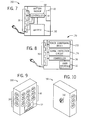
- FIGS. 5-10 illustrate a variety of power distribution devices 10 in accordance with the current specification.
- FIG. 5 illustrates an in-wall outlet 130.
- the in-wall outlet 130 attaches to a wall (e.g., through an electrical box disposed in the wall).
- the in-wall outlet 130 includes power outlet modules 30 and may include a user interface 32 used to configure the operational modes and configuration settings for the in-wall outlet 130.
- FIG. 6 illustrates an extension cord 140 with multiple power outlet modules 30.
- a user interface 32 may be disposed on a portion of the extension cord 140.
- the extension cord 140 may be useful in providing power outlet modules 30 at an extension distance from an in-wall outlet.
- the power outlet modules 30 are capable of being configured in a plurality of operational modes.
- the user interface 32 may be used to provide operational mode and configuration settings for the extension cord 140.
- the power distribution device 10 may also include a battery backup device 150, as illustrated in FIG. 7 .
- the battery backup device 150 may use a battery 152 to temporarily provide power to the power distribution device 10 upon an interruption in power being supplied to power distribution device 10.
- the battery 152 may provide power to the controller 68 and the power outlet modules 30.
- the battery backup device 150 may include a user interface 32, used to configure the operational mode and configuration settings of the battery backup device 150.
- FIG. 8 illustrates an embodiment of the power distribution device 10 including a power conditioning unit 170.
- the power conditioning unit 170 may include power conditioning circuitry 172 configured to improve the quality of power being delivered through the power conditioning unit 170.
- the power conditioning circuitry 172 may regulate a voltage of the power, may suppress noise, or provide transient impulse protection.
- the power conditioning unit 170 may include surge protection circuitry 174 configured to protect the power conditioning unit 170 from voltage spikes.
- the power conditioning unit 170 provides conditioned power to the power outlet modules 30, enabled to run in a plurality of operational modes via the controller 78.
- a user interface 32 may be included in the power conditioning unit 170 to configure the operational mode and configuration settings of the power conditioning unit 170.
- FIGS. 9 and 10 provide perspective views of an embodiment of the power distribution device 10 including a wall mount unit 190.
- the wall mount unit 190 may mount to a wall though an electrical coupling between electrical prongs 192 of the wall mount unit 190 with a wall outlet installed in the wall.
- the wall mount unit 190 includes power outlet modules 30, enabled to run in a plurality of operational modes via the controller 78. The operational modes and configuration settings may be configured through the use of a user interface 32 that may be included in the wall mount unit 190.
- the power distribution device is highly customizable by allowing a user to define operating modes for individual power outlet modules. Additionally, some operational modes may require the power distribution device to detect phantom currents or devices not in use.
- the power distribution device may be configurable to defme threshold current levels for devices connected to specific power outlet modules 30. Thus, the power distribution device provides a versatile solution for many different devices and/or combination of devices.
Landscapes
- Engineering & Computer Science (AREA)
- General Engineering & Computer Science (AREA)
- Theoretical Computer Science (AREA)
- Computer Hardware Design (AREA)
- Physics & Mathematics (AREA)
- General Physics & Mathematics (AREA)
- Remote Monitoring And Control Of Power-Distribution Networks (AREA)
- Supply And Distribution Of Alternating Current (AREA)
Applications Claiming Priority (1)
| Application Number | Priority Date | Filing Date | Title |
|---|---|---|---|
| US13/221,651 US20130049466A1 (en) | 2011-08-30 | 2011-08-30 | Programmable power management system |
Publications (2)
| Publication Number | Publication Date |
|---|---|
| EP2565747A2 true EP2565747A2 (fr) | 2013-03-06 |
| EP2565747A3 EP2565747A3 (fr) | 2013-11-27 |
Family
ID=47142897
Family Applications (1)
| Application Number | Title | Priority Date | Filing Date |
|---|---|---|---|
| EP20120182341 Withdrawn EP2565747A3 (fr) | 2011-08-30 | 2012-08-30 | Système de gestion dýénergie programmable |
Country Status (6)
| Country | Link |
|---|---|
| US (1) | US20130049466A1 (fr) |
| EP (1) | EP2565747A3 (fr) |
| JP (1) | JP2013051870A (fr) |
| AU (1) | AU2012216390A1 (fr) |
| BR (1) | BR102012020697A2 (fr) |
| CA (1) | CA2787571A1 (fr) |
Cited By (2)
| Publication number | Priority date | Publication date | Assignee | Title |
|---|---|---|---|---|
| FR3057712A1 (fr) * | 2016-10-13 | 2018-04-20 | We.Connect | Multiprise electrique programmable et systeme d'alimentation comportant une telle multiprise |
| FR3124901A1 (fr) * | 2021-07-05 | 2023-01-06 | Alstom Transport Technologies | Système ferroviaire comprenant au moins deux éléments de charge électrique ferroviaires propres à être alimentés par une ligne d’alimentation |
Families Citing this family (62)
| Publication number | Priority date | Publication date | Assignee | Title |
|---|---|---|---|---|
| US8094034B2 (en) | 2007-09-18 | 2012-01-10 | Georgia Tech Research Corporation | Detecting actuation of electrical devices using electrical noise over a power line |
| CN103168400B (zh) * | 2010-09-30 | 2016-04-27 | 飓风香港有限公司 | 电源分配单元及与其配合的通讯装置、及电源分配系统 |
| US20120229515A1 (en) * | 2010-10-07 | 2012-09-13 | Huimin Cao | Auto-Orientation of Display of a Power Distribution Unit |
| US9502896B2 (en) * | 2012-02-03 | 2016-11-22 | Monolith Amalgamation Llc | Systems and methods for the timed power up of electronic devices |
| US9425978B2 (en) * | 2012-06-27 | 2016-08-23 | Ubiquiti Networks, Inc. | Method and apparatus for configuring and controlling interfacing devices |
| US10184963B2 (en) * | 2012-06-28 | 2019-01-22 | Electronic Systems Protection, Inc. | Power quality diagnosis for power conditioning |
| US20140028097A1 (en) * | 2012-07-24 | 2014-01-30 | Dennis Harold AUGUR | Electrical outlet adapter with automatic power-on and power-off of peripheral outlets |
| US9219339B2 (en) * | 2012-10-12 | 2015-12-22 | Li-Chun Lai | Computer host power management system having extension cord sockets |
| EP2909875B1 (fr) | 2012-10-16 | 2020-06-17 | Ambri Inc. | Dispositifs et boîtiers pour le stockage d'énergie électrochimique |
| US11387497B2 (en) | 2012-10-18 | 2022-07-12 | Ambri Inc. | Electrochemical energy storage devices |
| US11211641B2 (en) | 2012-10-18 | 2021-12-28 | Ambri Inc. | Electrochemical energy storage devices |
| US9312522B2 (en) | 2012-10-18 | 2016-04-12 | Ambri Inc. | Electrochemical energy storage devices |
| US9735450B2 (en) | 2012-10-18 | 2017-08-15 | Ambri Inc. | Electrochemical energy storage devices |
| US10541451B2 (en) | 2012-10-18 | 2020-01-21 | Ambri Inc. | Electrochemical energy storage devices |
| US11721841B2 (en) | 2012-10-18 | 2023-08-08 | Ambri Inc. | Electrochemical energy storage devices |
| US9520618B2 (en) | 2013-02-12 | 2016-12-13 | Ambri Inc. | Electrochemical energy storage devices |
| US10270139B1 (en) | 2013-03-14 | 2019-04-23 | Ambri Inc. | Systems and methods for recycling electrochemical energy storage devices |
| US20140335919A1 (en) * | 2013-05-10 | 2014-11-13 | Brian N. Stewart | Electronic charging device |
| US9502737B2 (en) | 2013-05-23 | 2016-11-22 | Ambri Inc. | Voltage-enhanced energy storage devices |
| JP2014240900A (ja) * | 2013-06-11 | 2014-12-25 | 株式会社リコー | 情報処理装置、電力管理プログラム、電力管理方法及び電力管理システム |
| WO2015009350A1 (fr) | 2013-07-16 | 2015-01-22 | Leeo, Inc. | Dispositif électronique doté d'une surveillance de l'environnement |
| US9116137B1 (en) | 2014-07-15 | 2015-08-25 | Leeo, Inc. | Selective electrical coupling based on environmental conditions |
| US12347832B2 (en) | 2013-09-18 | 2025-07-01 | Ambri, LLC | Electrochemical energy storage devices |
| DK3058605T3 (da) | 2013-10-16 | 2024-03-04 | Ambri Inc | Tætninger til anordninger af reaktivt højtemperaturmateriale |
| WO2015058165A1 (fr) | 2013-10-17 | 2015-04-23 | Ambri Inc. | Systèmes de gestion de batterie pour des dispositifs de stockage d'énergie |
| US12142735B1 (en) | 2013-11-01 | 2024-11-12 | Ambri, Inc. | Thermal management of liquid metal batteries |
| US9170625B1 (en) | 2014-07-15 | 2015-10-27 | Leeo, Inc. | Selective electrical coupling based on environmental conditions |
| US9372477B2 (en) | 2014-07-15 | 2016-06-21 | Leeo, Inc. | Selective electrical coupling based on environmental conditions |
| US9213327B1 (en) * | 2014-07-15 | 2015-12-15 | Leeo, Inc. | Selective electrical coupling based on environmental conditions |
| TWM491881U (zh) * | 2014-08-05 | 2014-12-11 | Changshu Inforay Technology Co Ltd | 觸控式電源插座 |
| US9092060B1 (en) | 2014-08-27 | 2015-07-28 | Leeo, Inc. | Intuitive thermal user interface |
| KR20170049568A (ko) * | 2014-09-04 | 2017-05-10 | 유니버시티 오브 워싱톤 | 단일 센싱 포인트로부터 전자 디바이스의 사용자-구동 동작 상태를 검출하는 방법 |
| US10078865B2 (en) | 2014-09-08 | 2018-09-18 | Leeo, Inc. | Sensor-data sub-contracting during environmental monitoring |
| US10026304B2 (en) | 2014-10-20 | 2018-07-17 | Leeo, Inc. | Calibrating an environmental monitoring device |
| US9445451B2 (en) | 2014-10-20 | 2016-09-13 | Leeo, Inc. | Communicating arbitrary attributes using a predefined characteristic |
| WO2016109751A1 (fr) * | 2014-12-31 | 2016-07-07 | Jouler Inc. | Appareil modulaire pour fournir de l'énergie portable et gérer la consommation d'énergie |
| CN104635540A (zh) * | 2014-12-31 | 2015-05-20 | 苏州市龙源电力科技股份有限公司 | 一种电力模拟屏控制系统 |
| US10181800B1 (en) | 2015-03-02 | 2019-01-15 | Ambri Inc. | Power conversion systems for energy storage devices |
| WO2016141354A2 (fr) | 2015-03-05 | 2016-09-09 | Ambri Inc. | Céramiques et joints pour dispositifs de matériau réactif à haute température |
| US9893385B1 (en) | 2015-04-23 | 2018-02-13 | Ambri Inc. | Battery management systems for energy storage devices |
| US11133703B2 (en) | 2015-07-13 | 2021-09-28 | Vertiv Corporation | Method and apparatus to retrieve data from power distribution units |
| WO2017011541A1 (fr) * | 2015-07-13 | 2017-01-19 | Pce, Inc. | Procédé et appareil pour extraire des données d'unités de distribution d'énergie |
| CN107850928B (zh) * | 2015-07-13 | 2020-12-29 | 维提公司 | 用以从配电单元检索数据的方法及设备 |
| US9801013B2 (en) | 2015-11-06 | 2017-10-24 | Leeo, Inc. | Electronic-device association based on location duration |
| US10805775B2 (en) | 2015-11-06 | 2020-10-13 | Jon Castor | Electronic-device detection and activity association |
| CN105470739A (zh) * | 2015-12-21 | 2016-04-06 | 苏州翠南电子科技有限公司 | 一种时钟定时插座 |
| US11929466B2 (en) | 2016-09-07 | 2024-03-12 | Ambri Inc. | Electrochemical energy storage devices |
| TWI622241B (zh) * | 2016-11-07 | 2018-04-21 | 台達電子工業股份有限公司 | 具熱插拔智能模組之電源分配單元及其所適用之電源管理系統 |
| US10177651B2 (en) * | 2016-12-20 | 2019-01-08 | Mercury Magnetics, Inc. | System for controlling inrush current to eliminate inrush overcurrent to electrical equipment |
| KR20180082696A (ko) * | 2017-01-10 | 2018-07-19 | (주) 코콤 | 전기 플러그에 내장 가능한 사물인터넷 구성 방법 |
| CN110731027B (zh) | 2017-04-07 | 2024-06-18 | 安保瑞公司 | 具有固体金属阴极的熔盐电池 |
| TWI610507B (zh) * | 2017-06-08 | 2018-01-01 | 可程式化交流電源分配器 | |
| US20180358804A1 (en) * | 2017-06-13 | 2018-12-13 | Illinois Tool Works Inc. | Electrical cables with integral surge protection |
| US10996735B2 (en) * | 2017-07-13 | 2021-05-04 | Hygge Power Inc. | Power management system |
| WO2020131617A1 (fr) | 2018-12-17 | 2020-06-25 | Ambri Inc. | Systèmes et procédés de stockage d'énergie à haute température |
| US11243592B2 (en) * | 2019-08-15 | 2022-02-08 | Dell Products L.P. | System and method for controlling a power-on sequence and power throttling using power brake |
| US11506693B2 (en) * | 2019-10-11 | 2022-11-22 | Landis+Gyr Innovations, Inc. | Meter and socket for use with a distributed energy resource device |
| KR102502019B1 (ko) * | 2019-11-01 | 2023-02-22 | 주식회사 네트워크코리아 | 분배 제어 장치 |
| US11476665B2 (en) | 2020-08-18 | 2022-10-18 | Hygge Power Inc. | Mitigation of power outages |
| US12051503B2 (en) * | 2021-02-26 | 2024-07-30 | Gyrus Acmi, Inc. | Operating room power distribution techniques |
| WO2022266230A1 (fr) * | 2021-06-15 | 2022-12-22 | Splitvolt, Inc. | Procédé et appareil de séparation et de commande intelligentes d'une sortie haute tension |
| US20250337201A1 (en) * | 2024-04-30 | 2025-10-30 | Vertiv Corporation | Wall plug uninterruptible power supply |
Family Cites Families (33)
| Publication number | Priority date | Publication date | Assignee | Title |
|---|---|---|---|---|
| US5424903A (en) * | 1993-01-12 | 1995-06-13 | Tandy Corporation | Intelligent power switcher |
| US5563455A (en) * | 1995-02-27 | 1996-10-08 | Sun Microsystems, Inc. | Method and apparatus for sequencing and controlling power distribution |
| US6211581B1 (en) * | 1997-11-28 | 2001-04-03 | Harvard M. Farrant | Power bar with remote control |
| US6509655B1 (en) * | 2000-06-01 | 2003-01-21 | Peace Wang | System including electronically-controlled power strip having a plurality of receptacles |
| US20020185916A1 (en) * | 2000-12-15 | 2002-12-12 | Bruce Barton | Apparatus for controlling power distribution to devices |
| US6744150B2 (en) * | 2001-12-03 | 2004-06-01 | Neven V. Rendic | Outlet strip controlled by PC using low voltage powertap |
| GB2386004B (en) * | 2001-12-07 | 2005-08-24 | Peter Steven Robertson | Socket assembly |
| CN2534717Y (zh) * | 2002-03-21 | 2003-02-05 | 周义雄 | 主/从插座控制装置 |
| US6759762B2 (en) * | 2002-05-10 | 2004-07-06 | Bits Ltd | Device for controlling power distribution to subsystems |
| CA2449635A1 (fr) * | 2003-11-18 | 2005-05-18 | Electronic System Integrators Pty Ltd. | Connecteur d'alimentation |
| US20060273663A1 (en) * | 2005-06-02 | 2006-12-07 | Bradley Emalfarb | Power outlet with automatic shutoff |
| GB2427514B (en) * | 2005-06-21 | 2007-08-01 | Peter Robertson | Socket assembly with standby sockets |
| KR100801042B1 (ko) * | 2005-09-02 | 2008-02-11 | 김선영 | 자동전원차단콘센트 |
| CA2632180C (fr) * | 2005-11-30 | 2011-08-09 | Seong-Kyu Lim | Receptacle de sortie a regulation de courant |
| NZ578653A (en) * | 2006-12-27 | 2011-03-31 | Electronic Data Control Pty Ltd | Personal computer power control method and device |
| US20080164768A1 (en) * | 2007-01-09 | 2008-07-10 | Litwack Mark W | Energy-saving electrical adaptor |
| KR100935186B1 (ko) * | 2007-06-27 | 2010-01-06 | 임성규 | 플러그장치 |
| US20090146494A1 (en) * | 2007-10-03 | 2009-06-11 | Belkin International, Inc. | Apparatus For Providing Electrical Power To Electrical Device And Method Of Use |
| US20090215319A1 (en) * | 2008-02-21 | 2009-08-27 | Hanoz Gandhi | Green Power Strip |
| US7800251B2 (en) * | 2007-10-18 | 2010-09-21 | Hammerhead International, Llc | System and method for load control |
| US7944086B2 (en) * | 2007-10-18 | 2011-05-17 | Hammerhead International, Llc | System and method for load control |
| TWI329948B (en) * | 2007-12-10 | 2010-09-01 | Ind Tech Res Inst | Smart client-server socket |
| KR101006818B1 (ko) * | 2007-12-12 | 2011-01-10 | 이근진 | 콘센트 대기 전력 감소장치 |
| WO2009082484A1 (fr) * | 2007-12-26 | 2009-07-02 | Audiovox Corporation | Système de protection domotique |
| TWI360268B (en) * | 2008-02-05 | 2012-03-11 | Remote control duo power set | |
| US7986056B2 (en) * | 2008-04-03 | 2011-07-26 | Augur Dennis Harold | Electrical outlet adapter with automatic power-on and power-off of peripheral outlets |
| TWI364143B (en) * | 2008-10-22 | 2012-05-11 | An outlet apparatus with power classification management | |
| TW201025213A (en) * | 2008-12-31 | 2010-07-01 | Powertech Ind Ltd | Wireless controlled apparatus with power save mode |
| TWI365572B (en) * | 2008-12-31 | 2012-06-01 | Remote controllable power outlet apparatus with grouping capability and grouping remote control method | |
| TW201028838A (en) * | 2009-01-19 | 2010-08-01 | Delta Electronics Inc | Standby power-saving system and computer power-on & power-off method thereof |
| US8159084B2 (en) * | 2009-05-13 | 2012-04-17 | Briggs & Stratton Corporation | Power distribution device |
| TWI374591B (en) * | 2009-05-25 | 2012-10-11 | Master/slave outlets apparatus with sequencing and controlling function | |
| US8129859B2 (en) * | 2009-08-24 | 2012-03-06 | Hurco Automation, Ltd. | Extension cord with wireless timing function |
-
2011
- 2011-08-30 US US13/221,651 patent/US20130049466A1/en not_active Abandoned
-
2012
- 2012-08-17 BR BRBR102012020697-8A patent/BR102012020697A2/pt not_active IP Right Cessation
- 2012-08-22 AU AU2012216390A patent/AU2012216390A1/en not_active Abandoned
- 2012-08-23 CA CA 2787571 patent/CA2787571A1/fr not_active Abandoned
- 2012-08-27 JP JP2012186135A patent/JP2013051870A/ja active Pending
- 2012-08-30 EP EP20120182341 patent/EP2565747A3/fr not_active Withdrawn
Non-Patent Citations (1)
| Title |
|---|
| None |
Cited By (2)
| Publication number | Priority date | Publication date | Assignee | Title |
|---|---|---|---|---|
| FR3057712A1 (fr) * | 2016-10-13 | 2018-04-20 | We.Connect | Multiprise electrique programmable et systeme d'alimentation comportant une telle multiprise |
| FR3124901A1 (fr) * | 2021-07-05 | 2023-01-06 | Alstom Transport Technologies | Système ferroviaire comprenant au moins deux éléments de charge électrique ferroviaires propres à être alimentés par une ligne d’alimentation |
Also Published As
| Publication number | Publication date |
|---|---|
| US20130049466A1 (en) | 2013-02-28 |
| EP2565747A3 (fr) | 2013-11-27 |
| CA2787571A1 (fr) | 2013-02-28 |
| AU2012216390A1 (en) | 2013-03-21 |
| JP2013051870A (ja) | 2013-03-14 |
| BR102012020697A2 (pt) | 2013-11-12 |
Similar Documents
| Publication | Publication Date | Title |
|---|---|---|
| EP2565747A2 (fr) | Système de gestion dýénergie programmable | |
| CN101194217B (zh) | 使用固态功率控制器的配电系统 | |
| AU2007327557B2 (en) | Power supply control device | |
| US7986056B2 (en) | Electrical outlet adapter with automatic power-on and power-off of peripheral outlets | |
| US20140028097A1 (en) | Electrical outlet adapter with automatic power-on and power-off of peripheral outlets | |
| WO2014052193A4 (fr) | Système de gestion électrique local automatique | |
| EP3125374A1 (fr) | Dispositif de commande de fonctionnement pour appareil électronique | |
| GB2427514A (en) | Power distribution socket assembly with standby sockets | |
| CN102483643B (zh) | 使用选择性上限设定来管理多个负载的电能分配 | |
| CN104808761A (zh) | 一种供电方法、供电系统及电子设备 | |
| CN102104275A (zh) | 具有切换开关的电表 | |
| KR101073809B1 (ko) | 스마트 대기전력 자동차단 스위치 | |
| KR100994375B1 (ko) | 스마트 미터가 내장된 대기전력 차단 콘센트 | |
| KR100871672B1 (ko) | 절전형 멀티콘센트 및 그 구동방법 | |
| KR200464008Y1 (ko) | 콘센트 제어 장치 및 전력 관리 시스템 | |
| KR101485343B1 (ko) | 수요반응 기능을 지원하지 않는 전기기기를 위한 수요반응 전력 제어 방법 및 장치 | |
| KR20150111804A (ko) | 지능형 전원 플러그 및 전원 어댑터 | |
| KR101063438B1 (ko) | 대기전력 절감형 멀티콘센트 | |
| US9454217B1 (en) | Monitoring, controlling and reducing vampire power using a central controller in a network of power switch routers | |
| KR20150005345A (ko) | 전력 관리 장치 및 그를 이용한 전력 관리 시스템 | |
| CN108475993B (zh) | 电力恢复系统和方法 | |
| CN204928122U (zh) | 一种直流电流分配单元dcdu的配电系统 | |
| JP5096951B2 (ja) | 電源システム、及び電源制御方法 | |
| TWI455436B (zh) | Power management system | |
| CN201656144U (zh) | 一种能消除用电器待机能耗的智能插座 |
Legal Events
| Date | Code | Title | Description |
|---|---|---|---|
| PUAI | Public reference made under article 153(3) epc to a published international application that has entered the european phase |
Free format text: ORIGINAL CODE: 0009012 |
|
| AK | Designated contracting states |
Kind code of ref document: A2 Designated state(s): AL AT BE BG CH CY CZ DE DK EE ES FI FR GB GR HR HU IE IS IT LI LT LU LV MC MK MT NL NO PL PT RO RS SE SI SK SM TR |
|
| AX | Request for extension of the european patent |
Extension state: BA ME |
|
| PUAL | Search report despatched |
Free format text: ORIGINAL CODE: 0009013 |
|
| AK | Designated contracting states |
Kind code of ref document: A3 Designated state(s): AL AT BE BG CH CY CZ DE DK EE ES FI FR GB GR HR HU IE IS IT LI LT LU LV MC MK MT NL NO PL PT RO RS SE SI SK SM TR |
|
| AX | Request for extension of the european patent |
Extension state: BA ME |
|
| RIC1 | Information provided on ipc code assigned before grant |
Ipc: G06F 1/26 20060101AFI20131018BHEP Ipc: H01R 25/00 20060101ALI20131018BHEP Ipc: H01R 13/703 20060101ALI20131018BHEP |
|
| STAA | Information on the status of an ep patent application or granted ep patent |
Free format text: STATUS: THE APPLICATION IS DEEMED TO BE WITHDRAWN |
|
| 18D | Application deemed to be withdrawn |
Effective date: 20140528 |