EP2566036A2 - Verfahren und Vorrichtung zur Steuerung von zwei Leistungschaltern, insbesondere für ein Induktionskochgerät - Google Patents
Verfahren und Vorrichtung zur Steuerung von zwei Leistungschaltern, insbesondere für ein Induktionskochgerät Download PDFInfo
- Publication number
- EP2566036A2 EP2566036A2 EP12182335A EP12182335A EP2566036A2 EP 2566036 A2 EP2566036 A2 EP 2566036A2 EP 12182335 A EP12182335 A EP 12182335A EP 12182335 A EP12182335 A EP 12182335A EP 2566036 A2 EP2566036 A2 EP 2566036A2
- Authority
- EP
- European Patent Office
- Prior art keywords
- state
- power elements
- control signal
- inductor
- frequency control
- Prior art date
- Legal status (The legal status is an assumption and is not a legal conclusion. Google has not performed a legal analysis and makes no representation as to the accuracy of the status listed.)
- Granted
Links
Images




Classifications
-
- H—ELECTRICITY
- H02—GENERATION; CONVERSION OR DISTRIBUTION OF ELECTRIC POWER
- H02M—APPARATUS FOR CONVERSION BETWEEN AC AND AC, BETWEEN AC AND DC, OR BETWEEN DC AND DC, AND FOR USE WITH MAINS OR SIMILAR POWER SUPPLY SYSTEMS; CONVERSION OF DC OR AC INPUT POWER INTO SURGE OUTPUT POWER; CONTROL OR REGULATION THEREOF
- H02M7/00—Conversion of AC power input into DC power output; Conversion of DC power input into AC power output
- H02M7/42—Conversion of DC power input into AC power output without possibility of reversal
- H02M7/44—Conversion of DC power input into AC power output without possibility of reversal by static converters
- H02M7/48—Conversion of DC power input into AC power output without possibility of reversal by static converters using discharge tubes with control electrode or semiconductor devices with control electrode
- H02M7/53—Conversion of DC power input into AC power output without possibility of reversal by static converters using discharge tubes with control electrode or semiconductor devices with control electrode using devices of a triode or transistor type requiring continuous application of a control signal
- H02M7/537—Conversion of DC power input into AC power output without possibility of reversal by static converters using discharge tubes with control electrode or semiconductor devices with control electrode using devices of a triode or transistor type requiring continuous application of a control signal using semiconductor devices only, e.g. single switched pulse inverters
- H02M7/5387—Conversion of DC power input into AC power output without possibility of reversal by static converters using discharge tubes with control electrode or semiconductor devices with control electrode using devices of a triode or transistor type requiring continuous application of a control signal using semiconductor devices only, e.g. single switched pulse inverters in a bridge configuration
- H02M7/53871—Conversion of DC power input into AC power output without possibility of reversal by static converters using discharge tubes with control electrode or semiconductor devices with control electrode using devices of a triode or transistor type requiring continuous application of a control signal using semiconductor devices only, e.g. single switched pulse inverters in a bridge configuration with automatic control of output voltage or current
-
- H—ELECTRICITY
- H02—GENERATION; CONVERSION OR DISTRIBUTION OF ELECTRIC POWER
- H02M—APPARATUS FOR CONVERSION BETWEEN AC AND AC, BETWEEN AC AND DC, OR BETWEEN DC AND DC, AND FOR USE WITH MAINS OR SIMILAR POWER SUPPLY SYSTEMS; CONVERSION OF DC OR AC INPUT POWER INTO SURGE OUTPUT POWER; CONTROL OR REGULATION THEREOF
- H02M1/00—Details of apparatus for conversion
- H02M1/36—Means for starting or stopping converters
-
- H—ELECTRICITY
- H02—GENERATION; CONVERSION OR DISTRIBUTION OF ELECTRIC POWER
- H02M—APPARATUS FOR CONVERSION BETWEEN AC AND AC, BETWEEN AC AND DC, OR BETWEEN DC AND DC, AND FOR USE WITH MAINS OR SIMILAR POWER SUPPLY SYSTEMS; CONVERSION OF DC OR AC INPUT POWER INTO SURGE OUTPUT POWER; CONTROL OR REGULATION THEREOF
- H02M7/00—Conversion of AC power input into DC power output; Conversion of DC power input into AC power output
- H02M7/42—Conversion of DC power input into AC power output without possibility of reversal
- H02M7/44—Conversion of DC power input into AC power output without possibility of reversal by static converters
- H02M7/48—Conversion of DC power input into AC power output without possibility of reversal by static converters using discharge tubes with control electrode or semiconductor devices with control electrode
- H02M7/53—Conversion of DC power input into AC power output without possibility of reversal by static converters using discharge tubes with control electrode or semiconductor devices with control electrode using devices of a triode or transistor type requiring continuous application of a control signal
- H02M7/537—Conversion of DC power input into AC power output without possibility of reversal by static converters using discharge tubes with control electrode or semiconductor devices with control electrode using devices of a triode or transistor type requiring continuous application of a control signal using semiconductor devices only, e.g. single switched pulse inverters
- H02M7/5387—Conversion of DC power input into AC power output without possibility of reversal by static converters using discharge tubes with control electrode or semiconductor devices with control electrode using devices of a triode or transistor type requiring continuous application of a control signal using semiconductor devices only, e.g. single switched pulse inverters in a bridge configuration
-
- H—ELECTRICITY
- H05—ELECTRIC TECHNIQUES NOT OTHERWISE PROVIDED FOR
- H05B—ELECTRIC HEATING; ELECTRIC LIGHT SOURCES NOT OTHERWISE PROVIDED FOR; CIRCUIT ARRANGEMENTS FOR ELECTRIC LIGHT SOURCES, IN GENERAL
- H05B6/00—Heating by electric, magnetic or electromagnetic fields
- H05B6/02—Induction heating
- H05B6/06—Control, e.g. of temperature, of power
- H05B6/062—Control, e.g. of temperature, of power for cooking plates or the like
-
- H—ELECTRICITY
- H02—GENERATION; CONVERSION OR DISTRIBUTION OF ELECTRIC POWER
- H02M—APPARATUS FOR CONVERSION BETWEEN AC AND AC, BETWEEN AC AND DC, OR BETWEEN DC AND DC, AND FOR USE WITH MAINS OR SIMILAR POWER SUPPLY SYSTEMS; CONVERSION OF DC OR AC INPUT POWER INTO SURGE OUTPUT POWER; CONTROL OR REGULATION THEREOF
- H02M7/00—Conversion of AC power input into DC power output; Conversion of DC power input into AC power output
- H02M7/42—Conversion of DC power input into AC power output without possibility of reversal
- H02M7/44—Conversion of DC power input into AC power output without possibility of reversal by static converters
- H02M7/48—Conversion of DC power input into AC power output without possibility of reversal by static converters using discharge tubes with control electrode or semiconductor devices with control electrode
- H02M7/4815—Resonant converters
-
- Y—GENERAL TAGGING OF NEW TECHNOLOGICAL DEVELOPMENTS; GENERAL TAGGING OF CROSS-SECTIONAL TECHNOLOGIES SPANNING OVER SEVERAL SECTIONS OF THE IPC; TECHNICAL SUBJECTS COVERED BY FORMER USPC CROSS-REFERENCE ART COLLECTIONS [XRACs] AND DIGESTS
- Y02—TECHNOLOGIES OR APPLICATIONS FOR MITIGATION OR ADAPTATION AGAINST CLIMATE CHANGE
- Y02B—CLIMATE CHANGE MITIGATION TECHNOLOGIES RELATED TO BUILDINGS, e.g. HOUSING, HOUSE APPLIANCES OR RELATED END-USER APPLICATIONS
- Y02B70/00—Technologies for an efficient end-user side electric power management and consumption
- Y02B70/10—Technologies improving the efficiency by using switched-mode power supplies [SMPS], i.e. efficient power electronics conversion e.g. power factor correction or reduction of losses in power supplies or efficient standby modes
Definitions
- the present invention relates to a method and a device for controlling two half-bridge power elements for generating an alternating electric current in an inductor.
- the present invention relates to the field of power supply of an induction cooking appliance, such as an induction table, comprising one or more cooking zones equipped with an inductor.
- Each cooking zone is controlled by two power elements mounted according to a half-bridge circuit topology.
- the two half-bridge mounted power elements for controlling the inductor are IGBT (Insulated Gate Bipolar Transistor) components.
- the two power elements are controlled by a frequency control signal F, as illustrated in FIG. figure 1 .
- control means of the power elements are adapted to generate a first control signal Com1 of a first power element and a second control signal Com2 of a second power element to alternately position these two power elements respectively in an ON state and a OFF state.
- This step of controlling the two power elements is illustrated in FIG. figure 1 on a first period of time T.
- stopping the alternating current generated in the inductor is obtained by simultaneously blocking the two power elements, that is to say by placing the two control signals Com1, Com2 at a logic level corresponding to the blocked state OFF both power elements.
- the control of the two power elements mounted half bridge requires, in addition to the frequency control signal F, a logic signal S allowing the simultaneous blocking of the two power elements.
- the present invention aims to solve at least one of the aforementioned drawbacks and to simplify the control of two power elements mounted half bridge.
- the present invention relates to a method for controlling two half-bridge-mounted power elements for generating an alternating electric current in an inductor, comprising a step of controlling the two power elements by a frequency control signal. adapted to alternately position the two power elements respectively in an on state and a blocked state.
- this control method comprises a step of extinguishing the alternating electric current generated in the inductor, in which one of said two power elements is maintained in an on state and the other of said two power elements is maintained. in a blocked state.
- the two power elements are respectively maintained in an on state and in a locked state during the extinction step by the frequency control signal.
- control method requires the use of a single signal to drive the two power elements.
- the frequency control signal is sufficient to control the two power elements, both to generate the alternating electric current and to extinguish it in the inductor.
- control method further comprises a step of securing the two power elements after the step of extinguishing the alternating electric current, in which the two power elements are maintained. in a blocked state.
- the extinction of the alternating current in the inductor can be obtained while maintaining one of the power elements in an on state, it is preferable, after the step of extinguishing the alternating current in the inductor, to simultaneously block both power elements to avoid any risk of short circuit in the system at a standstill.
- the two power elements are kept in a blocked state by a logic signal of predefined value, activated by the frequency control signal.
- the activation of the logic signal for tilting and maintaining in a locked state the two power elements can be obtained directly by using the frequency control signal and without requiring an additional control signal in the system.
- the frequency control signal is an alternating signal between a high state and a low state, the frequency control signal being maintained at a high state or a low state during the phase of extinction of the alternating electric current.
- the present invention relates to a device for controlling two half-bridge-mounted power elements for generating an alternating electric current in an inductor, comprising means for controlling the two power elements by a frequency control signal. adapted to alternately position the two power elements respectively in an on state and a blocked state.
- control means are adapted, during a step of extinguishing the alternating electric current generated in the inductor, to maintain one of said two power elements in an on state and the other of said two elements of power. power in a blocked state.
- This control device has characteristics and advantages similar to those described above in relation to the control method according to the invention.
- the present invention relates to an induction cooking appliance comprising at least one cooking zone equipped with an inductor.
- this cooking appliance comprises a device for controlling two half-bridge-mounted power elements for generating an alternating electric current in an inductor, as previously described in relation to the control device.
- This cooking appliance also has characteristics and advantages similar to those described above in relation to the control method according to the invention.
- the induction cooking appliance may in particular be an induction table comprising at least one cooking zone comprising an inductor L.
- the cooking appliance comprises several cooking zones, each cooking zone being controlled by two power elements.
- the inductor L schematically represents the induction cooking zone and may correspond to one or more inductor windings connected in series, thus constituting a cooking zone.
- the inductor L is driven by two power elements T1, T2 mounted in half-bridge to generate an alternating electric current in the inductor L, called in the following induction current I.
- the power elements are IGBT components.
- the half-bridge assembly of the two power elements T1, T2 is conventional and is presented briefly below.
- Each power element T1, T2 is connected in parallel between its collector C and its emitter E to a freewheeling diode D1, D2 and a switching aid capacitor C1, C2.
- Resonance capacitors, C3, C4 are mounted to form a resonant circuit with the inductor L which is associated with a resistor R representing the resistance of a container placed on the cooking zone, above the inductor L.
- controlling the two power elements T1, T2 by a control signal at a given frequency F makes it possible to alternately position the two power elements T1, T2 in an on state and in a locked state, and to generate thus an alternating current circulating in the inductor L.
- control of the power elements T1, T2 is carried out from control means 30 as illustrated in detail in FIG. figure 3 .
- control signals Com1, Com2 respectively addressed to the power elements T1, T2 are generated by the control means 30.
- control means 30 include in this embodiment a controller 31 (also called in English terminology “ driver "), itself controlled by a microprocessor 32.
- the microprocessor 32 controls the controller 31 by a single frequency control signal F.
- the frequency control signal F is an alternating signal between a high state and a low state.
- the frequency control signal F is a square signal.
- control signal Com1 of the first power element T1 sends an on state ON to the first power element T1
- control signal Com2 of the second power element T2 sends a blocked state OFF to the second power element T2, and vice versa.
- control signals Com1, Com2 are alternated in order to switch each power element from an ON state to a OFF state, and vice versa.
- control means 30 are adapted to maintain one of the two power elements T1, T2 in a ON state and the other two power elements T1, T2 in an off state OFF.
- the first power element T1 is kept in an off state OFF while the second power element T2 is kept in an ON state.
- the Figure 4B illustrates the opposite situation, in which the first power element T1 is kept in an on state ON and the second power element T2 is kept in an off state OFF.
- the control means 30 are adapted to drive the power elements T1, T2 by the frequency control signal F.
- the frequency control signal F being here an alternating signal between a high state and a low state, it is maintained at the output of the microprocessor 32 or at a low state ( Figure 4A ) to a high state ( Figure 4B ) from the given instant t beginning the extinction step.
- control of the two power elements T1, T2 can be achieved using a single frequency control signal F, and the microprocessor 32 may have only one output.
- This arrangement is particularly advantageous when the piloting of several half-bridge topologies by a microprocessor is implemented in a cooking appliance.
- the frequency control signal F here has a frequency of 20 kHz.
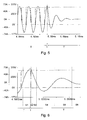
- Inductor current I is illustrated by a solid line curve.
- the voltage between the collector C and the emitter E of the first power element T1 is shown in broken lines and the voltage between the collector C and the emitter E of the second power element T2 is shown in phantom.
- the figure 5 illustrates the alternation of the voltages across the first and second power elements T1, T2, which conventionally makes it possible to generate the alternating electric current in the inductor L.
- an extinction phase of the inductor current I is implemented over a second period of time T '.
- the first command Com1 addressed to the gate G of the first power element T1 is turned OFF and the second command Com2 addressed to the gate G of the second power element T2 is turned on. ON during the shutdown step.
- the figure 5 thus illustrates the second period of time T 'attenuation then extinction of the inductor current I.
- the figure 6 illustrates in more detail the different steps involved in the extinction of this inductive current I.
- a first step S1 before the given instant t of the extinction phase, the first power element T1 is in an ON state.
- the frequency control signal F is set to the low state as illustrated in FIG. Figure 4A .
- the first power element T1 is put in an off state OFF.
- the inductor current I then flows in the two switching aid capacitors C1, C2.
- the voltage between the collector C and the emitter E of the first power element T1 increases and the voltage between the collector C and the emitter E of the second power element T2 decreases.
- the voltage between the collector C and the emitter E of the second power element T2 becomes negative.
- the freewheeling diode D2 associated with the second power element T2 then becomes conducting.
- the inductor current I then flows in the freewheeling diode D2 until this current is canceled.
- step S4 when the inductor current I vanishes and becomes negative, the freewheeling diode D2 is blocked and the second power element T2 then becomes on.
- the inductor current I then flows in the second power element T2 until it cancels out and becomes positive again.
- Step S6 the inductor current I then flows back into the second power element T2. Steps S5 and S6 are repeated thus until complete cancellation of the inductor current I.
- the inductor current I flows only in the second power element T2 and the associated freewheel diode D2 until its extinction.
- the blocking of one of the power elements T1, T2 can be obtained by a single frequency control signal F maintained in a high state or in a low state during the extinction phase of the inductor current I.
- a second embodiment of the invention provides a step of securing the two power elements T1, T2 after the step of extinguishing the alternating electric current.
- This safety is obtained by keeping the two power elements T1, T2 in a OFF state.
- This control device has elements similar to those described above in relation to the figure 3 .
- the control means 30 further comprise an activation circuit A of a logic signal S addressed to the input of the controller 31 of the power elements T1, T2.
- This logic signal S is activated directly by the frequency control signal F through the activation circuit A.
- the logic signal S can take two values 0 or 1, a predefined value, for example equal to 1, corresponding to a command addressed to the controller 31 to obtain the maintenance of the two power elements T1, T2 in an off state OFF .
- the frequency control signal F can be used directly to enable or disable a cutoff input at the controller 31 (input "shut down” in English terminology).
- the frequency control signal F is addressed at the input of a first transistor T5, through a first capacitor C5.
- This first transistor T5 is connected by its collector to a DC voltage source, for example equal to 5 V.
- the emitter of the first transistor T5 is mounted through a resistor on a second capacitor C6, itself connected through a voltage divider bridge to the base of a second transistor T6 mounted at the input of the controller 31.
- the first transistor T5 switches to the frequency F and charges the second capacitor C6 to the value of 5 V.
- This voltage across the second capacitor C6 keeps the second transistor T6 in an ON state.
- the input of the controller 31 is thus maintained at a value 0, corresponding to an inactive value of the logic signal S.
- control signals Com1, Com2 of the two power elements T1, T2 are freely controlled by the controller 31, and as previously indicated, directly by the frequency control signal F sent to the controller 31.
- the frequency control signal F has a zero frequency, that is to say that the frequency control signal F is kept in a high state or in a low state
- the first transistor T5 is in a state. OFF state.
- the second capacitor C6 then discharges into the activation circuit A, the voltage across its terminals decreasing here from 5V to a zero value during a time interval ⁇ .
- the second transistor T6 is switched and held in an off state OFF such that the logic signal S at the input of the controller 31 is activated and shows the preset value 1.
- This logic signal S addressed to the controller 31 thus controls the two control signals Com1, Com2 to address an off state OFF to the two power elements T1, T2.
- the extinction of the current is obtained by maintaining in a high state the frequency control signal F, as previously described in relation to the Figure 4B .
- the first power element T1 is maintained in the on state ON and the second power element T2 is maintained in a second state. state off OFF so that the AC current is turned off in the inductor.
- a signal is generated after the time interval ⁇ starting from the instant t.
- logic S preset value here equal to 1, for placing and maintaining in a OFF state OFF the two power elements T1, T2.
- this time interval ⁇ is of the order of a few milliseconds, and for example equal to 10 milliseconds, that is to say relatively large compared to the period of the order of 50 microseconds of the control signal. in frequency F.
- the extinction of the alternating current in the inductor can be obtained very quickly by controlling the controller 31 directly from the frequency control signal F, the safety of the two power elements T1, T2 then intervening after the step of extinguishing the alternating current in the inductor.
- control method described above can be implemented in any type of induction cooking appliance, for controlling an inductor controlled by a half-bridge topology.
- the invention is not limited to the exemplary embodiments in which the power elements T1, T2 are maintained in an on state and in a blocked state during the step of extinguishing the current by means of a single signal frequency control.
- a specific signal could also be sent by the microprocessor 32 to the controller 31 to obtain the maintenance of one of the power elements in an on state and the other of the power elements in a blocked state in order to obtain extinction. of the inductive current.
Landscapes
- Engineering & Computer Science (AREA)
- Power Engineering (AREA)
- Physics & Mathematics (AREA)
- Electromagnetism (AREA)
- Inverter Devices (AREA)
- Induction Heating Cooking Devices (AREA)
- General Induction Heating (AREA)
Applications Claiming Priority (1)
| Application Number | Priority Date | Filing Date | Title |
|---|---|---|---|
| FR1157657A FR2979500B1 (fr) | 2011-08-30 | 2011-08-30 | Procede et dispositif de commande de deux elements de puissance, notamment pour appareil de cuisson a induction |
Publications (3)
| Publication Number | Publication Date |
|---|---|
| EP2566036A2 true EP2566036A2 (de) | 2013-03-06 |
| EP2566036A3 EP2566036A3 (de) | 2017-10-04 |
| EP2566036B1 EP2566036B1 (de) | 2021-04-28 |
Family
ID=46888907
Family Applications (1)
| Application Number | Title | Priority Date | Filing Date |
|---|---|---|---|
| EP12182335.5A Active EP2566036B1 (de) | 2011-08-30 | 2012-08-30 | Verfahren und Vorrichtung zur Steuerung von zwei Leistungschaltern, insbesondere für ein Induktionskochgerät |
Country Status (3)
| Country | Link |
|---|---|
| EP (1) | EP2566036B1 (de) |
| ES (1) | ES2879934T3 (de) |
| FR (1) | FR2979500B1 (de) |
Cited By (1)
| Publication number | Priority date | Publication date | Assignee | Title |
|---|---|---|---|---|
| EP2806328A1 (de) * | 2013-05-23 | 2014-11-26 | Fagorbrandt Sas | Kontrollsystem elektrischer Ladungen, das mindestens zwei Phasen eines elektrischen Verteilungsnetzes aufnimmt |
Families Citing this family (1)
| Publication number | Priority date | Publication date | Assignee | Title |
|---|---|---|---|---|
| CN109425811B (zh) * | 2017-08-21 | 2021-07-23 | 上海新微技术研发中心有限公司 | 一种igbt检测电路及检测方法 |
Family Cites Families (1)
| Publication number | Priority date | Publication date | Assignee | Title |
|---|---|---|---|---|
| JP2004171934A (ja) * | 2002-11-20 | 2004-06-17 | Matsushita Electric Ind Co Ltd | 誘導加熱装置 |
-
2011
- 2011-08-30 FR FR1157657A patent/FR2979500B1/fr active Active
-
2012
- 2012-08-30 EP EP12182335.5A patent/EP2566036B1/de active Active
- 2012-08-30 ES ES12182335T patent/ES2879934T3/es active Active
Non-Patent Citations (1)
| Title |
|---|
| None |
Cited By (2)
| Publication number | Priority date | Publication date | Assignee | Title |
|---|---|---|---|---|
| EP2806328A1 (de) * | 2013-05-23 | 2014-11-26 | Fagorbrandt Sas | Kontrollsystem elektrischer Ladungen, das mindestens zwei Phasen eines elektrischen Verteilungsnetzes aufnimmt |
| FR3006121A1 (fr) * | 2013-05-23 | 2014-11-28 | Fagorbrandt Sas | Systeme de controle de charges electriques recevant au moins deux phases d'un reseau de distribution electrique |
Also Published As
| Publication number | Publication date |
|---|---|
| FR2979500B1 (fr) | 2013-09-27 |
| EP2566036B1 (de) | 2021-04-28 |
| FR2979500A1 (fr) | 2013-03-01 |
| ES2879934T3 (es) | 2021-11-23 |
| EP2566036A3 (de) | 2017-10-04 |
Similar Documents
| Publication | Publication Date | Title |
|---|---|---|
| EP0788678B1 (de) | Verfahren und schaltungsanordnung zur leistungssteuerung einer last durch ein phasensteuerungssystem | |
| FR2829315A1 (fr) | Procede et appareil de commande des moteurs sans balais | |
| FR2573587A1 (fr) | Circuits de commande d'un moteur a induction | |
| FR3032071A1 (fr) | Circuit electrique comportant une pluralite d'elements resistifs connectes en parallele | |
| FR2509926A1 (fr) | Circuit d'onduleur a commutation rapide | |
| EP0271396A1 (de) | Verfahren und Vorrichtung zur Zündung von Entladungslampen | |
| EP2445306B1 (de) | Steuerverfahren für den Betrieb eines Induktionskochfeldes, und Induktionskochfeld, das dieses Verfahren benutzt | |
| EP2566036B1 (de) | Verfahren und Vorrichtung zur Steuerung von zwei Leistungschaltern, insbesondere für ein Induktionskochgerät | |
| FR2752135A1 (fr) | Procedes et dispositifs de commande de l'intensite de lampes fluorescentes | |
| EP0986288B1 (de) | Wechselstromwandlervorrichtung mit gesteuerter Leistungsabgabe | |
| EP2747514A1 (de) | Verfahren und Vorrichtung zur Leistungszuführung von Induktionsmitteln | |
| EP1580873A1 (de) | Vorrichtung und Verfahren zur Steuerung eines Umwandlers und Umwandler und eine solche Vorrichtung enthaltende Elektroinstallation | |
| EP2341757A1 (de) | Verfahren und Vorrichtung zur Bestimmung der minimalen induzierten Dauerleistung, insbesondere eines Induktionskochgeräts | |
| EP0616415A1 (de) | Schwingkreissteuerschaltung für einen Spannungswechselrichter mit Quasiresonanzbetrieb und pulsbreitmodulierter Regelung | |
| EP3809800B1 (de) | Verfahren zur leistungsteuerung mindestens eines induktors, und induktionskochgerät für die umsetzung dieses verfahrens | |
| EP1586157B1 (de) | Versorgungsgenerator für eine oszillationsschaltung insbesondere für einen induktionsherd | |
| WO2006092390A2 (fr) | Oscillateur de royer a electronique de decharge | |
| US20220103112A1 (en) | Method and device for actuating an electric machine, and electric drive system | |
| EP0538102B1 (de) | Energieversorungseinrichtung eines Ozonerzeugers | |
| EP1837987A1 (de) | Verfahren zur Parameteridentifizierung von einem Elektromotorkabel | |
| EP0538103B1 (de) | Verbesserte Energieversorgungseinrichtung eines Ozonerzeugers | |
| FR2612725A1 (fr) | Procede et circuit electrique pour le fonctionnement d'une lampe a decharge avec interruption du courant | |
| FR2473802A1 (fr) | Dispositif d'alimentation en courant electrique notamment pour dispositif de degivrage d'aeronef | |
| EP3540943A1 (de) | Regulierungsverfahren der stromeinspeiseleistung einer elektrischen vorrichtung | |
| EP1300934A1 (de) | Verfahren und Vorrichtung zur Gleichspannungswandlung und Gebrauch derselben Vorrichtung |
Legal Events
| Date | Code | Title | Description |
|---|---|---|---|
| PUAI | Public reference made under article 153(3) epc to a published international application that has entered the european phase |
Free format text: ORIGINAL CODE: 0009012 |
|
| AK | Designated contracting states |
Kind code of ref document: A2 Designated state(s): AL AT BE BG CH CY CZ DE DK EE ES FI FR GB GR HR HU IE IS IT LI LT LU LV MC MK MT NL NO PL PT RO RS SE SI SK SM TR |
|
| AX | Request for extension of the european patent |
Extension state: BA ME |
|
| 19U | Interruption of proceedings before grant |
Effective date: 20140411 |
|
| 19W | Proceedings resumed before grant after interruption of proceedings |
Effective date: 20150701 |
|
| RAP1 | Party data changed (applicant data changed or rights of an application transferred) |
Owner name: GROUPE BRANDT |
|
| 111Z | Information provided on other rights and legal means of execution |
Free format text: AL AT BE BG CH CY CZ DE DK EE ES FI FR GB GR HR HU IE IS IT LT LU LV MC MK MT NL NO PL PT RO RS SE SI SK SM TR Effective date: 20150915 |
|
| PUAL | Search report despatched |
Free format text: ORIGINAL CODE: 0009013 |
|
| AK | Designated contracting states |
Kind code of ref document: A3 Designated state(s): AL AT BE BG CH CY CZ DE DK EE ES FI FR GB GR HR HU IE IS IT LI LT LU LV MC MK MT NL NO PL PT RO RS SE SI SK SM TR |
|
| AX | Request for extension of the european patent |
Extension state: BA ME |
|
| RIC1 | Information provided on ipc code assigned before grant |
Ipc: H05B 6/12 20060101ALI20170828BHEP Ipc: H02M 1/36 20070101ALI20170828BHEP Ipc: H02M 7/5387 20070101AFI20170828BHEP |
|
| STAA | Information on the status of an ep patent application or granted ep patent |
Free format text: STATUS: REQUEST FOR EXAMINATION WAS MADE |
|
| 17P | Request for examination filed |
Effective date: 20180321 |
|
| RBV | Designated contracting states (corrected) |
Designated state(s): AL AT BE BG CH CY CZ DE DK EE ES FI FR GB GR HR HU IE IS IT LI LT LU LV MC MK MT NL NO PL PT RO RS SE SI SK SM TR |
|
| STAA | Information on the status of an ep patent application or granted ep patent |
Free format text: STATUS: EXAMINATION IS IN PROGRESS |
|
| 17Q | First examination report despatched |
Effective date: 20190220 |
|
| D11X | Information provided on other rights and legal means of execution (deleted) | ||
| GRAP | Despatch of communication of intention to grant a patent |
Free format text: ORIGINAL CODE: EPIDOSNIGR1 |
|
| STAA | Information on the status of an ep patent application or granted ep patent |
Free format text: STATUS: GRANT OF PATENT IS INTENDED |
|
| INTG | Intention to grant announced |
Effective date: 20201118 |
|
| GRAS | Grant fee paid |
Free format text: ORIGINAL CODE: EPIDOSNIGR3 |
|
| GRAA | (expected) grant |
Free format text: ORIGINAL CODE: 0009210 |
|
| STAA | Information on the status of an ep patent application or granted ep patent |
Free format text: STATUS: THE PATENT HAS BEEN GRANTED |
|
| AK | Designated contracting states |
Kind code of ref document: B1 Designated state(s): AL AT BE BG CH CY CZ DE DK EE ES FI FR GB GR HR HU IE IS IT LI LT LU LV MC MK MT NL NO PL PT RO RS SE SI SK SM TR |
|
| REG | Reference to a national code |
Ref country code: GB Ref legal event code: FG4D Free format text: NOT ENGLISH |
|
| REG | Reference to a national code |
Ref country code: CH Ref legal event code: EP |
|
| REG | Reference to a national code |
Ref country code: DE Ref legal event code: R096 Ref document number: 602012075368 Country of ref document: DE |
|
| REG | Reference to a national code |
Ref country code: AT Ref legal event code: REF Ref document number: 1388275 Country of ref document: AT Kind code of ref document: T Effective date: 20210515 |
|
| REG | Reference to a national code |
Ref country code: IE Ref legal event code: FG4D Free format text: LANGUAGE OF EP DOCUMENT: FRENCH |
|
| REG | Reference to a national code |
Ref country code: LT Ref legal event code: MG9D |
|
| REG | Reference to a national code |
Ref country code: AT Ref legal event code: MK05 Ref document number: 1388275 Country of ref document: AT Kind code of ref document: T Effective date: 20210428 |
|
| PG25 | Lapsed in a contracting state [announced via postgrant information from national office to epo] |
Ref country code: HR Free format text: LAPSE BECAUSE OF FAILURE TO SUBMIT A TRANSLATION OF THE DESCRIPTION OR TO PAY THE FEE WITHIN THE PRESCRIBED TIME-LIMIT Effective date: 20210428 Ref country code: AT Free format text: LAPSE BECAUSE OF FAILURE TO SUBMIT A TRANSLATION OF THE DESCRIPTION OR TO PAY THE FEE WITHIN THE PRESCRIBED TIME-LIMIT Effective date: 20210428 Ref country code: BG Free format text: LAPSE BECAUSE OF FAILURE TO SUBMIT A TRANSLATION OF THE DESCRIPTION OR TO PAY THE FEE WITHIN THE PRESCRIBED TIME-LIMIT Effective date: 20210728 Ref country code: FI Free format text: LAPSE BECAUSE OF FAILURE TO SUBMIT A TRANSLATION OF THE DESCRIPTION OR TO PAY THE FEE WITHIN THE PRESCRIBED TIME-LIMIT Effective date: 20210428 Ref country code: LT Free format text: LAPSE BECAUSE OF FAILURE TO SUBMIT A TRANSLATION OF THE DESCRIPTION OR TO PAY THE FEE WITHIN THE PRESCRIBED TIME-LIMIT Effective date: 20210428 Ref country code: NL Free format text: LAPSE BECAUSE OF FAILURE TO SUBMIT A TRANSLATION OF THE DESCRIPTION OR TO PAY THE FEE WITHIN THE PRESCRIBED TIME-LIMIT Effective date: 20210428 |
|
| REG | Reference to a national code |
Ref country code: ES Ref legal event code: FG2A Ref document number: 2879934 Country of ref document: ES Kind code of ref document: T3 Effective date: 20211123 |
|
| PG25 | Lapsed in a contracting state [announced via postgrant information from national office to epo] |
Ref country code: LV Free format text: LAPSE BECAUSE OF FAILURE TO SUBMIT A TRANSLATION OF THE DESCRIPTION OR TO PAY THE FEE WITHIN THE PRESCRIBED TIME-LIMIT Effective date: 20210428 Ref country code: GR Free format text: LAPSE BECAUSE OF FAILURE TO SUBMIT A TRANSLATION OF THE DESCRIPTION OR TO PAY THE FEE WITHIN THE PRESCRIBED TIME-LIMIT Effective date: 20210729 Ref country code: IS Free format text: LAPSE BECAUSE OF FAILURE TO SUBMIT A TRANSLATION OF THE DESCRIPTION OR TO PAY THE FEE WITHIN THE PRESCRIBED TIME-LIMIT Effective date: 20210828 Ref country code: RS Free format text: LAPSE BECAUSE OF FAILURE TO SUBMIT A TRANSLATION OF THE DESCRIPTION OR TO PAY THE FEE WITHIN THE PRESCRIBED TIME-LIMIT Effective date: 20210428 Ref country code: SE Free format text: LAPSE BECAUSE OF FAILURE TO SUBMIT A TRANSLATION OF THE DESCRIPTION OR TO PAY THE FEE WITHIN THE PRESCRIBED TIME-LIMIT Effective date: 20210428 Ref country code: NO Free format text: LAPSE BECAUSE OF FAILURE TO SUBMIT A TRANSLATION OF THE DESCRIPTION OR TO PAY THE FEE WITHIN THE PRESCRIBED TIME-LIMIT Effective date: 20210728 Ref country code: PT Free format text: LAPSE BECAUSE OF FAILURE TO SUBMIT A TRANSLATION OF THE DESCRIPTION OR TO PAY THE FEE WITHIN THE PRESCRIBED TIME-LIMIT Effective date: 20210830 Ref country code: PL Free format text: LAPSE BECAUSE OF FAILURE TO SUBMIT A TRANSLATION OF THE DESCRIPTION OR TO PAY THE FEE WITHIN THE PRESCRIBED TIME-LIMIT Effective date: 20210428 |
|
| REG | Reference to a national code |
Ref country code: NL Ref legal event code: MP Effective date: 20210428 |
|
| PG25 | Lapsed in a contracting state [announced via postgrant information from national office to epo] |
Ref country code: RO Free format text: LAPSE BECAUSE OF FAILURE TO SUBMIT A TRANSLATION OF THE DESCRIPTION OR TO PAY THE FEE WITHIN THE PRESCRIBED TIME-LIMIT Effective date: 20210428 Ref country code: SK Free format text: LAPSE BECAUSE OF FAILURE TO SUBMIT A TRANSLATION OF THE DESCRIPTION OR TO PAY THE FEE WITHIN THE PRESCRIBED TIME-LIMIT Effective date: 20210428 Ref country code: SM Free format text: LAPSE BECAUSE OF FAILURE TO SUBMIT A TRANSLATION OF THE DESCRIPTION OR TO PAY THE FEE WITHIN THE PRESCRIBED TIME-LIMIT Effective date: 20210428 Ref country code: DK Free format text: LAPSE BECAUSE OF FAILURE TO SUBMIT A TRANSLATION OF THE DESCRIPTION OR TO PAY THE FEE WITHIN THE PRESCRIBED TIME-LIMIT Effective date: 20210428 Ref country code: CZ Free format text: LAPSE BECAUSE OF FAILURE TO SUBMIT A TRANSLATION OF THE DESCRIPTION OR TO PAY THE FEE WITHIN THE PRESCRIBED TIME-LIMIT Effective date: 20210428 Ref country code: EE Free format text: LAPSE BECAUSE OF FAILURE TO SUBMIT A TRANSLATION OF THE DESCRIPTION OR TO PAY THE FEE WITHIN THE PRESCRIBED TIME-LIMIT Effective date: 20210428 |
|
| REG | Reference to a national code |
Ref country code: DE Ref legal event code: R097 Ref document number: 602012075368 Country of ref document: DE |
|
| PLBE | No opposition filed within time limit |
Free format text: ORIGINAL CODE: 0009261 |
|
| STAA | Information on the status of an ep patent application or granted ep patent |
Free format text: STATUS: NO OPPOSITION FILED WITHIN TIME LIMIT |
|
| REG | Reference to a national code |
Ref country code: CH Ref legal event code: PL |
|
| PG25 | Lapsed in a contracting state [announced via postgrant information from national office to epo] |
Ref country code: MC Free format text: LAPSE BECAUSE OF FAILURE TO SUBMIT A TRANSLATION OF THE DESCRIPTION OR TO PAY THE FEE WITHIN THE PRESCRIBED TIME-LIMIT Effective date: 20210428 |
|
| 26N | No opposition filed |
Effective date: 20220131 |
|
| REG | Reference to a national code |
Ref country code: BE Ref legal event code: MM Effective date: 20210831 |
|
| GBPC | Gb: european patent ceased through non-payment of renewal fee |
Effective date: 20210830 |
|
| PG25 | Lapsed in a contracting state [announced via postgrant information from national office to epo] |
Ref country code: LI Free format text: LAPSE BECAUSE OF NON-PAYMENT OF DUE FEES Effective date: 20210831 Ref country code: CH Free format text: LAPSE BECAUSE OF NON-PAYMENT OF DUE FEES Effective date: 20210831 |
|
| PG25 | Lapsed in a contracting state [announced via postgrant information from national office to epo] |
Ref country code: IS Free format text: LAPSE BECAUSE OF FAILURE TO SUBMIT A TRANSLATION OF THE DESCRIPTION OR TO PAY THE FEE WITHIN THE PRESCRIBED TIME-LIMIT Effective date: 20210828 Ref country code: LU Free format text: LAPSE BECAUSE OF NON-PAYMENT OF DUE FEES Effective date: 20210830 Ref country code: AL Free format text: LAPSE BECAUSE OF FAILURE TO SUBMIT A TRANSLATION OF THE DESCRIPTION OR TO PAY THE FEE WITHIN THE PRESCRIBED TIME-LIMIT Effective date: 20210428 |
|
| PG25 | Lapsed in a contracting state [announced via postgrant information from national office to epo] |
Ref country code: IE Free format text: LAPSE BECAUSE OF NON-PAYMENT OF DUE FEES Effective date: 20210830 Ref country code: GB Free format text: LAPSE BECAUSE OF NON-PAYMENT OF DUE FEES Effective date: 20210830 Ref country code: BE Free format text: LAPSE BECAUSE OF NON-PAYMENT OF DUE FEES Effective date: 20210831 |
|
| PG25 | Lapsed in a contracting state [announced via postgrant information from national office to epo] |
Ref country code: HU Free format text: LAPSE BECAUSE OF FAILURE TO SUBMIT A TRANSLATION OF THE DESCRIPTION OR TO PAY THE FEE WITHIN THE PRESCRIBED TIME-LIMIT; INVALID AB INITIO Effective date: 20120830 Ref country code: CY Free format text: LAPSE BECAUSE OF FAILURE TO SUBMIT A TRANSLATION OF THE DESCRIPTION OR TO PAY THE FEE WITHIN THE PRESCRIBED TIME-LIMIT Effective date: 20210428 |
|
| P01 | Opt-out of the competence of the unified patent court (upc) registered |
Effective date: 20230524 |
|
| PG25 | Lapsed in a contracting state [announced via postgrant information from national office to epo] |
Ref country code: MK Free format text: LAPSE BECAUSE OF FAILURE TO SUBMIT A TRANSLATION OF THE DESCRIPTION OR TO PAY THE FEE WITHIN THE PRESCRIBED TIME-LIMIT Effective date: 20210428 |
|
| PG25 | Lapsed in a contracting state [announced via postgrant information from national office to epo] |
Ref country code: TR Free format text: LAPSE BECAUSE OF FAILURE TO SUBMIT A TRANSLATION OF THE DESCRIPTION OR TO PAY THE FEE WITHIN THE PRESCRIBED TIME-LIMIT Effective date: 20210428 |
|
| PG25 | Lapsed in a contracting state [announced via postgrant information from national office to epo] |
Ref country code: MT Free format text: LAPSE BECAUSE OF FAILURE TO SUBMIT A TRANSLATION OF THE DESCRIPTION OR TO PAY THE FEE WITHIN THE PRESCRIBED TIME-LIMIT Effective date: 20210428 |
|
| PGFP | Annual fee paid to national office [announced via postgrant information from national office to epo] |
Ref country code: ES Payment date: 20250908 Year of fee payment: 14 |
|
| PGFP | Annual fee paid to national office [announced via postgrant information from national office to epo] |
Ref country code: DE Payment date: 20250812 Year of fee payment: 14 |
|
| PGFP | Annual fee paid to national office [announced via postgrant information from national office to epo] |
Ref country code: IT Payment date: 20250808 Year of fee payment: 14 |
|
| PGFP | Annual fee paid to national office [announced via postgrant information from national office to epo] |
Ref country code: FR Payment date: 20250820 Year of fee payment: 14 |