EP2566355B1 - Machine et procédé pour fabriquer des filtres de cigarette - Google Patents
Machine et procédé pour fabriquer des filtres de cigarette Download PDFInfo
- Publication number
- EP2566355B1 EP2566355B1 EP11714397.4A EP11714397A EP2566355B1 EP 2566355 B1 EP2566355 B1 EP 2566355B1 EP 11714397 A EP11714397 A EP 11714397A EP 2566355 B1 EP2566355 B1 EP 2566355B1
- Authority
- EP
- European Patent Office
- Prior art keywords
- filter
- track
- along
- segments
- combining
- Prior art date
- Legal status (The legal status is an assumption and is not a legal conclusion. Google has not performed a legal analysis and makes no representation as to the accuracy of the status listed.)
- Not-in-force
Links
Images



Classifications
-
- A—HUMAN NECESSITIES
- A24—TOBACCO; CIGARS; CIGARETTES; SIMULATED SMOKING DEVICES; SMOKERS' REQUISITES
- A24D—CIGARS; CIGARETTES; TOBACCO SMOKE FILTERS; MOUTHPIECES OF CIGARS OR CIGARETTES; MANUFACTURE OF TOBACCO SMOKE FILTERS OR MOUTHPIECES
- A24D3/00—Tobacco smoke filters, e.g. filter tips or filtering inserts; Filters specially adapted for simulated smoking devices; Mouthpieces of cigars or cigarettes
- A24D3/02—Manufacture of tobacco smoke filters
- A24D3/0275—Manufacture of tobacco smoke filters for filters with special features
- A24D3/0287—Manufacture of tobacco smoke filters for filters with special features for composite filters
Definitions
- the present invention relates to a machine and a method for making cigarette filters, in particular composite cigarette filters, i.e. filters comprising two or more segments of filtering material.
- the above mentioned segments can be either arranged according to a continuous line, to form a succession of combined filters, or separated from one another by spaces, to form a succession of recess filters.
- the several segments can be made either of different filtering materials or of the same filtering material, which can be impregnated or not with liquid additives or, in general, with particulates, for instance in powder form.
- the machines for making composite filters are usually of the type described in WO-2009/074540 and FR-1280722 ; they generally comprise a combining device provided with an inlet for each type of segment and with an outlet for filter elements comprising a combination of segments of the above mentioned segment types.
- the object of the present invention is to provide a machine and a method for making cigarette filters, in particular composite filters, that are easy and economical to be produced and, at the same time, guarantee high flexibility as regards changes in segment format and distribution and a relatively low energy consumption.
- a machine for making cigarette filters according to claim 1 and, preferably, according to any one of the claims depending directly or indirectly upon the claim 1.
- a method is also provided for making cigarette filters according to claim 19 and, preferably, according to any one of the claims depending directly or indirectly upon the claim 19.
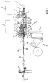
- number 1 indicates, in its entirety, a machine for making cigarette filters, in particular cigarette composite filters.
- the machine 1 is suitable to produce a succession of double filters, generically indicated with the number 2, each of which comprises, in the present case, at least one segment 3 and at least one segment 4, which present equal lengths in the illustrated example but in reality can present different lengths.
- the segments 3 and 4 are arranged inside a tubular casing 5 either according to a continuous line, to define a succession of double filters 2 which must be subsequently cut to obtain combined filters 2a ( figure 6 ), or according to a line comprising spaces 6, to define a succession of double filters 2 which must be subsequently cut to obtain recess filters 2b ( figure 7 ).
- the segments 3 and 4 can be of different filtering materials or of the same filtering material, which is not impregnated for one of the two segments 3 and 4, while is impregnated with particulate material for the other of the two segments 3 and 4.
- the material of both the segments 3 and 4 can also be impregnated in different manners.
- the segment 3 can be made of cellulose acetate
- the segment 4 can be made of cellulose acetate impregnated with carbon dust.
- the segments 3 and 4 are obtained by transversally cutting respective rods 7 ( figure 5 ) extracted in a known manner from respective hoppers 8 and 9 by means of respective extracting and cutting units 10, each of which comprises an extracting roller 11 externally provided with axial grooves 12.
- the extracting roller is mounted for rotation, in counterclockwise direction in figure 1 , around a horizontal axis 13; moreover, it is arranged to close an exit of the respective hopper 8, 9 and, along a part of its own periphery, into contact with the rods 7 contained in the respective hopper 8, 9.
- the grooves 12 are sucking grooves uniformly distributed around the axis 13 and each of them is suitable to receive and hold a respective rod 7, and to move this rod 7 along a circular path to extract it from the respective hopper 8, 9 and to engage it with a succession of cutting units 14, through which the rod 7 is cut into the respective segments 3, 4.
- the machine 1 comprises a combining device 15 to combine segments 3 and 4 to obtain a cited ordered succession ( figure 6 and 7 ) that can be chosen among a plurality of ordered successions obtainable by combining segments 3 and 4 of different dimensions and spaces 6, as the case may be.
- each of these ordered successions is obtained starting from the formation of a series of filter groups 16 through the combining device 15 and according to a given law variable from ordered succession to ordered succession; each of these filter groups 16, as it will be described hereafter, can be constituted even by a single segment 3 or 4 or part of it, and can be equal to, or different from, the two adjacent filter groups 16 preceding and, respectively, following it in the series.
- the combining device 15 comprises a rectangular plate 17 arranged horizontally and presenting a longitudinal rear edge 18, which is arranged transversally to the axes 13 and along which the adjacent hoppers 8 and 9 and the respective extracting and cutting groups 10 are mounted, and a longitudinal front edge 19, parallel to the longitudinal rear edge 18.
- the plate 17 is arranged at a lower level than that of the plane defined by the two axes 13 and presents an upper surface 20, whose plane is tangent to the outer surfaces of both the extracting rollers 11.
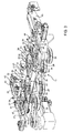
- the combining device 15 furthermore comprises four wheels 21, 22, 23, and 24, wherein the wheels 21 and 24 are inlet wheels for respective feeding lines for the segments 3 and 4, the wheel 23 is a transferring wheel of the feeding line of the segments 4, and the wheel 22 is an outlet combining wheel coupled to both the cited feeding lines.
- wheels 21-24 are of the same type, only the wheel 21 will be described in detail hereinafter. Obviously, the detailed description below applies to all the remaining wheels 22-24.
- the wheel 21 comprises a shaft 25, which presents a vertical axis 26 perpendicular to the plate 17 and is mounted in a rotatable and axially fixed manner through a cylindrical sleeve 27 coaxial to the axis 26 and engaged in fixed position by means of a through hole 28 obtained in the plate 17.
- a pulley 29 is keyed, which is carried into rotation, together with the other pulleys 29, by a belt 30 actuated by a motor 31.
- the pulley 30 is suitable to put the wheels 21 and 23 into counterclockwise rotation and the wheel 22 and 24 in clockwise rotation.
- the relative peripheral speed of ach wheel 22-24 relative to the other wheels is of major significance in management of the machine 1; and it should be furthermore noted that the configuration of figure 3 , wherein all the pulleys 29 have the same diameter and the respective wheels 21-24 have therefore the same peripheral speed, can be suitable to obtain a particular double filter 2, for instance the double filter 2 of figure 6 , while the use of pulleys 29, presenting different diameters, will be necessary for obtaining double filters 2 of different type.
- each of the wheels 22-24 is motorized through a respective motor, in particular an adjustable speed electric motor.
- the grooves swept by the teeth 33 of the wheels 21 to 24 define respective annular tracks, respectively indicated with 37, 38, 39, and 40 and extending on the plate 17 coaxially to the respective axes 26, wherein the track 38 presents a first portion common to the track 37 and a second portion common to the track 39, which presents a portion common to the track 40.
- the tracks 37 and 40 are inlet tracks for the respective feeding lines of the segments 3 and 4
- the track 39 is a transfer track of the feeding line of the segments 4
- the track 38 is an outlet track comprising a part, which is substantially tangent to the longitudinal front edge 19 of the plate 17, is arranged downstream of the cited second portion and upstream of the cited first portion of the track 38 in the direction of rotation of the wheel 22, and presents a radial opening which is an outlet 41 of the combining device 15.
- an appendix 42 extends outwards from each end of the longitudinal rear edge 18 of the plate 17; this appendix is perpendicular to the longitudinal rear edge 18, supports, together with a frame 43 for supporting the plate 17, the respective hopper 8, 9 and presents an upper surface coplanar with the upper surface 20 of the plate 17.
- Each appendix 42 extends below, and substantially tangentially to, the respective extracting roller 11 and is followed by a respective rectilinear slit 44, which is tangential to the respective wheel 21, 24 and extends along the plate 17 until it exits inside the respective track 37, 40.
- the slit 44 defines a rectilinear inlet track for the respective segments 3, 4 inside the combining device 15.
- each slit 44 is parallel to each other, but they are inclined relative to the axes 13 of the respective extracting rollers 11. Namely, while each axis 13 is perpendicular to the longitudinal rear edge 18 of the plate 17 and is parallel to the peripheral grooves 12 of the respective extracting roller 11, each slit 44 is inclined forward, in the direction of rotation of the respective extracting roller 11 and relative to a peripheral groove 12 facing it, starting from a rear end of the peripheral groove 12.
- Each of the slits 44 defines a feeding path for a succession of rods 7 extracted by the respective extracting roller 11 from the respective hopper 8, 9.
- each slit 44 is associated to a respective transport system 45, which is suitable to transfer the rods 7 from the respective extracting roller 11 to the respective track 37, 40 and comprises a conveyor 46 and an accelerating unit 47.
- Each conveyor 46 is a pocket conveyor comprising a motorized annular chain 48, which presents a transport branch extending immediately below the respective slit 44 and is provided with teeth 49, which are movable along the slit 44, project above the upper surface 20 and are suitable to engage in a slidable manner respective peripheral grooves 12 of the respective extracting roller 11 when this latter rotates about the respective axis 13.
- Each accelerating unit 47 comprises two motorized endless conveyors 50 and 51, which are arranged along the respective slit 44 at opposite sides of the plate 17 and present transport branches parallel to and facing one another, defining between themselves, and along the respective slit 44, an advancement channel 52 for the segments 3, 4 (or portions thereof) of the respective rods 7.
- the conveyor 50 is arranged below the plate 17 and its transport branch is coplanar, and aligned, with the transport branch of the chain 48 and presents an inlet rear end, which is joined, through a slab 53, to the front end of the transport branch of the respective conveyor 46.
- the machine 1 comprises an outlet section 54 of the substantially known type, which in turn comprises a forming beam 55, of the known type, supported by the frame 43 and arranged with an its own inlet portion along the longitudinal front edge 19 of the plate 17; a feeding unit 56, of the known type, for feeding a paper strip 57 that moves, in use, along the forming beam 55 in a direction 58 and defines a conveyor to advance, in the direction 58, the filtering material exiting from the outlet 41; a transfer group 59, of the known type, for transferring the filtering material from the combining device 15 to the forming beam 55 above the conveyor defined by the paper strip 57 for forming, along the forming beam 55 and in a known manner, a continuous filter worm 60; and a rotating cutting head 61, of the known type, suitable to cut transversally the continuous worm 60 to obtain a succession of segments, each of which corresponds to a double filter 2.
- the transfer group 59 is arranged above the level of the plate 17; however, a (non-illustrated) embodiment is also provided, according to which the transfer group 59 is arranged below the level of the plate 17; but in this case the transfer wheels constituting the transfer group 59 are more than three and comprise at least two further end wheels to bring the filtering material above the conveyor defined by the paper strip 57.
- the transfer group 59 comprises, in the illustrated example, three gear wheels 63, 64, and 65 of the centrifugal type, i.e. similar to that of the wheels 21-24.
- the wheels 63, 64, and 65 are rotatable about respective axes parallel to the axis 13, are arranged aligned on a vertical plane passing through the longitudinal front edge 19 of the plate 17, and are provided with respective transport pockets, each of which is suitable to receive a respective filter group 16, constituted by the content of a corresponding transport pocket 36 of the combining wheel 22.
- the wheel 63 is an inlet wheel, which is rotatable in phase with the combining wheel 22 and in clockwise direction in figure 2 , and is arranged in a position tangential to the track 38 at the radial opening 41;
- the wheel 65 is an outlet wheel, which is rotatable clockwise in figure 2 and is arranged above the inlet of the forming beam 55 tangentially to the strip 57;
- the wheel 64 is an intermediate wheel, which is tangential to the wheels 63 and 65 and is rotatable counterclockwise in figure 2 and in phase with the wheels 63 and 65.
- the wheels 63 and 64 have a common motorization and rotate in phase with the combining wheel 22 and with a peripheral speed comprised between the peripheral speed VC of the combining wheel 22 and the speed VN of advancement of the strip 57.
- the ratio between the peripheral speed of the wheels 63 and 64 and the peripheral speed of the combining wheel 22 is equal to the ratio between the length of the transport pockets of the wheels 63 and 64 and the length of the transport pockets 36 of the combining wheel 22.
- the wheel 65 (and in any case the last wheel of the transfer group 59) is usually provided with an independent motorisation and presents a peripheral speed VT, which is comprised between the peripheral speed of the wheels 63 and 64 and the speed VN of advancement of the strip 57.
- the advancement of the filter groups 16 between the radial opening 41 and the forming beam 55 is therefore obtained by making a controlled braking, i.e. with a speed decreasing from the peripheral speed VC of the combining wheel 22 to the speed VN of the strip 57 by means of one, two, or three speed jumps.
- each extracting roller 11 is put into counterclockwise rotation about the respective axis 13 with a constant peripheral speed V1, which can be different from the constant speed V1 of the other extracting roller.
- each groove 12 takes a respective rod 7 and move it forward through the cutting unit 14, which transforms it into a succession of segments 3 or of segments 4 or of fractions thereof, adjacent to one another.
- Each extracting roller 11 and the respective conveyor 46 are mutually synchronised so that, when a groove 12 is in a position facing the upper surface 20 of the plate 17 and tangential to it, the respective cut rod 7 enters transversally inside a transport pocket of the conveyor 46 and the tooth 49, which limits this pocket at the back, engages the rear end of the cited groove 12 and moves along this groove extracting the cut rod 7 and moving it towards the inlet of the channel 52 with the speed V2.
- This operation is possible thanks to the fact that the slit 44 and the transport branch of the conveyor 46 are inclined by the angle "a" relative to the groove 12, allowing the tooth 49 to follow the groove 12 even if the groove 12 continues to translate parallel to itself with the speed V1.
- the above mentioned transport pockets 36 are defined by the wheel 21 and move with the speed V4, indicated hereinafter with V4a, along the track 37; as regards the segments 4, the above mentioned transport pockets 36 are defined instead by the wheel 24 and move with the speed V4b (which can be different from the speed V4a together with the respective speed V3) along the track 40.
- the wheels 21-24 are synchronised with one another so that the segments 3 are directly transferred from a transport pocket 36 of the wheel 21 to a respective given position inside a transport pocket 36 of the wheel 22; and the segments 4 are transferred from a transport pocket 36 of the wheel 24 to a transport pocket 36 of the wheel 23 and then to a respective given position inside a transport pocket 36 of the wheel 22.
- the synchronisation of the wheels 21-24 is such that, immediately upstream of the outlet 41, the segments 3 and 4 are ordered, along the periphery of the combining wheel 22, according to a given order corresponding to that of the sequence to be formed on the forming beam 55.
- This example relates to the formation of a sequence such as that illustrated in figure 6 .
- This sequence can be obtained according to three different methods.
- All the wheels 21-24 are actuated with a same peripheral speed V4, but the wheel 21 is substantially in phase with the combining wheel 22, and the wheels 23 and 24 are in phase with one another, but slightly in advance relative to the combining wheel 22. This advance can be in the order of half the length of a transport pocket 36 of the combining wheel 22.
- each transport pocket 36 of the combining wheel 22 receives from the wheel 21 a segment 3, which, once entered inside the cited transport pocket 36, immediately comes into contact with the rear tooth 35 of the transport pocket 36.
- the cited transport pocket 36 of the combining wheel 22 receives from the wheel 23 a segment 4, which moves in front of the respective segment 3 and comes immediately into contact with it to form a filter group 16, which is constituted by a segment 4 and a segment 3, in series and into contact with each other, and which coincides with a module 16a repeating the ordered succession to be formed along the forming beam 55.
- the distance D is zeroed through a controlled "braking" obtained by means of at least one speed jump made during the transfer of the filter groups 16 from the combining wheel 22 to the forming beam 55.
- the succession of figure 6 is therefore formed on the strip 57, and this succession, once it has been packed with the strip 57, is cut by the cutting head 61 into a succession of double filters 2, which will be then cut in two to obtain single filters 2a, on a subsequent filter-adder machine (not illustrated).
- All the wheels 21, 23, and 24 are actuated with a same peripheral speed V4, but the wheel 21 is out of phase relative to the wheels 23 and 24 by a distance equal to the length L2+K of the transport pocket 36 of the combining wheel 22; while the combining wheel 22 is actuated with a speed VC equal to the double of the speed V4 and so that inside one of the pockets of each pair of transport pockets 36 of the combining wheel 22 a filter group 16 is formed, constituted by a segment 3, and inside the other pocket a filter group 16 is formed, constituted by a segment 4.
- the extracting and cutting group 10 is set so as to feed half a segment 3 inside each transport pocket 36 of the wheel 21; furthermore, the wheels 21 and 22 are actuated with a same peripheral speed V4 and in phase with each other, while the wheels 23 and 24 are actuated with a speed equal to half the speed V4.
- the filter group 16 constituted by half segment 3 is, in this case, shorter than the filter group 16 constituted by half segment 3 and a segment 4, using the "Method 3" and applying a different controlled braking it will be possible to obtain a sequence (not illustrated) enabling the production of double filters 2, which comprise, in succession, a half segment 4, a half segment 3, a space S, a half segment 3 and a half segment 4.
- double filters 2 can be therefore cut into two halves to obtain a pair of cigarette filters, each of which comprising a half space S (mouth side), a half segment 3 and a half segment 4 (cigarette side).
- This example relates to the formation of a sequence such as that illustrated in figure 7 .
- the double filters 2 are produced in two distinct phases, the first of which, performed by the combining device 15, is a phase of combining and ordering segments 3 and 4 to form, inside the transport pockets 36 of the wheel 22, a succession of filter groups 16, whose structures and order are a function of the reciprocal phasing and of the relative speeds of the wheels 21-24; and the second of which, performed by moving forward the filter groups 16 from the combining device 15 to the cutting head 61, is a composing and cutting phase, during which the initial distribution of the filter groups 16, imposed by the distribution of the transport pockets 36 of the combining wheel 22, is changed by imparting a controlled braking to the filter groups 16 during their transfer from the combining device 15 to the forming beam 55, and setting this braking it is possible to obtain compact sequences for producing filters 2a or recess sequences for producing filters 2b.
- the filter groups 16 are maintained, in a known manner and through suction, in their end relative positions during their advancement along the conveyor defined by the strip 57, which, moving forward along the forming beam 55, is folded, in a known manner, transversally around the succession of filter groups 16 to form the filter worm 60, which is fed with continuous motion through a cutting station, wherein the cutting head 61 cuts the worm 60 to form the double filters 2.
- the machine 1 described above presents some distinctive features constituted by the facts that:
- the machine 66 substantially corresponds to two machines 1, wherein the plates 17 have been made integral to one another along their longitudinal front edges 19 to form a single plate 69, the hoppers for the rods 7 are four, are generically indicated with the number 70 and are arranged in pairs at opposite sides of the plate 69, and there are two series of wheels 21-24, wherein the two combining wheels 22 are tangential to each other and share the radial opening 41.
- a single outlet section 54 with a single forming beam 55 there are a single feeding unit 56 for feeding a single paper strip 57 and a single transfer group 59 for transferring the filter groups (not illustrated) from the single outlet 41 to the forming beam 55 above the strip 57 to produce on the paper strip 57 ordered successions (not illustrated) comprising four types of segments compacted together or spaced.
- the four hoppers 70 are arranged in pairs along the branches of a L and along two contiguous edges of a plate 71 supporting eight wheels, generically indicated with the number 72, similar to the wheels 21-24, one of which, indicated with 72a, is a combining wheel allowing the formation, on a single not illustrated forming beam, of ordered successions (not illustrated) comprising four types of segment compacted together or spaced.
- the four hoppers 70 are arranged in pairs along the branches of a T and along two contiguous edges of a plate 73 supporting nine wheels, generically indicated with the number 74, similar to the wheels 21-24, one of which, indicated with 74a, is a combining wheel allowing the formation, on a single not illustrated forming beam, of ordered successions (not illustrated) comprising four types of segments compacted together or spaced.
- each of these machines is constituted by two mutually integrated modules, and that each of these modules is constituted by a machine 1, that has its own plate 17 common to the other machine 1.
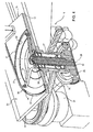
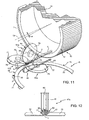
- the variant illustrated in figures 11 and 12 relates to a different accelerating unit, indicated with the number 47a, suitable to be used instead of each accelerating unit 47 and, analogously to this latter, to receive in succession the rods 7 from the chain 48 and to accelerate the respective segments 3, 4 to feed them singularly to the transport pockets 36 of the respective wheel 21, 24.
- Each accelerating unit 47a comprises two conveyors 50a and 51a, which are arranged along the respective slit 44 at opposite sides of the plate 17 and which define between themselves along the slit 44 the advancement channel 52 for the segments 3, 4 of the respective rods 7.
- the conveyor 50a is arranged below the plate 17 and comprises two disks 75, which are motorized, to rotate in opposite directions around respective axes 76 extending perpendicularly to the plate 17, and are arranged substantially tangential to one another.
- the disks 75 are arranged coplanar to one another and to the transport branch of the chain 48 and at opposite sides of the elongation of the transport branch, and they are externally limited by respective frusto-conical surfaces 77, which are arranged with their conicities facing upwards and define, between themselves and at the zone of substantial tangency, a lower surface portion of the channel (52).
- the actuation of the disks 75 is such that, in use, the peripheral speeds V3 of the frusto-conical surfaces 77 at their zone of substantial tangency are equal to one another and concordant with the linear speed V2 of advancement of the teeth 49 of the chain 48.
- the conveyor 51a is arranged above the plate 17 and comprises a pulley 78, which is motorized to rotate around an axis 79 parallel to the plate 17, perpendicular to the axes 76 and extending on a plane defined by the axes 76.
- the pulley 78 is directly arranged above the zone of substantial tangency of the disks 75 and presents an outer annular groove 80, whose peripheral speed V3 is equal to, and concordant with, in the zone of substantial tangency of the disks 75, the peripheral speed V3 of the disks 75 and defines, at the zone of substantial tangency of the disks 75, an upper surface portion of the channel 52.
Landscapes
- Cigarettes, Filters, And Manufacturing Of Filters (AREA)
- Filtering Of Dispersed Particles In Gases (AREA)
- Vending Machines For Individual Products (AREA)
Claims (22)
- Machine de fabrication de filtres pour la fabrication des filtres de cigarette segmentés (2 ; 2a ; 2b), la machine (1) comprenant une première partie apte à combiner un certain nombre de segments de filtre (3, 4) et une deuxième partie apte à composer et à couper les filtres (2 ; 2a ; 2b) ; la première partie comprenant au moins un dispositif de combinaison (15) apte à combiner plusieurs types de segments de filtre (3, 4) réalisés en plusieurs types de matières filtrantes afin d'obtenir une succession de groupes de filtres segmentés (16), le dispositif de combinaison (15) ayant une entrée (44) pour chaque type de segments de filtre (3, 4) et une sortie (41) pour les groupes de filtres (16) ; et la machine (1) étant caractérisée en ce que le dispositif de combinaison (15) comprend une plaque horizontale (17) ayant, au niveau du côté supérieur, une succession de pistes (37-40) adaptées pour être suivies en partie par les segments (3, 4) et en partie par les groupes de filtres (16) ; la plaque (17) définissant une surface d'appui et de support pour les segments de filtre (3, 4) et les groupes de filtres (16) qui se déplacent, en cours d'utilisation, le long des pistes (37-40) ; chaque piste (37 ; 38 ; 39 ; 40) étant tangente à chaque piste adjacente (37 ; 38 ; 39 ; 40), et communiquant avec celle-ci ; et les entrées (44) et la sortie (41) étant associées à des pistes respectives (37 ; 40 ; 38).
- Machine de fabrication de filtres telle que revendiquée dans la revendication 1, dans laquelle chaque piste (37 ; 38 ; 39 ; 40) est une piste annulaire s'étendant autour d'un axe respectif (26) qui est perpendiculaire à la plaque (17) ; des moyens formant roues (21 ; 22 ; 23 ; 24) étant portés par la plaque (17) coaxialement (26) pour faire avancer les segments de filtre (3, 4) et/ou les groupes de filtres (16) le long de la piste (37 ; 38 ; 39 ; 40).
- Machine de fabrication de filtres telle que revendiquée dans la revendication 2, dans laquelle, pour chacune desdites pistes (37 ; 38 ; 39 ; 40), les moyens formant roues (21 ; 22 ; 23 ; 24) comprennent un anneau plat motorisé (33) qui est coaxial audit axe (26) et a une pluralité de dents (35) pour balayer la piste (37 ; 38 ; 39 ; 40), les dents (45).
- Machine de fabrication de filtres telle que revendiquée dans la revendication 2 ou 3, et comprenant en outre au moins deux trémies (8, 9) pour des types respectifs de segments de filtre (3 ; 4) ; chaque trémie (8 ; 9) étant associée à une entrée respective (44) qui comprend une piste droite s'étendant, au moins en partie, le long de la plaque (17) et tangente à ladite piste annulaire respective (37 ; 40), qui est une piste d'entrée (37 ; 40) pour le dispositif de combinaison (15) ; des moyens d'extraction (11) étant prévus pour extraire les segments de filtre (3, 4) à partir de chaque trémie (8, 9) ; et des moyens convoyeurs (45) étant mobiles le long de la piste droite pour transporter les segments de filtre (3, 4) depuis les moyens d'extraction (11) jusqu'à la piste d'entrée respective (37 ; 40).
- Machine de fabrication de filtres telle que revendiquée dans la revendication 4, dans laquelle chaque trémie (8, 9) est conçue pour recevoir une pluralité de tiges de filtre (7) d'un type respectif de matières filtrantes ; les moyens d'extraction (11) comprenant, pour chaque trémie (8, 9), un rouleau d'extraction motorisé (11) monté en rotation sur un axe horizontal (13) et ayant des rainures axiales périphériques (12) chacune adaptée pour recevoir et retenir ladite tige de filtre respective (7).
- Machine de fabrication de filtres telle que revendiquée dans la revendication 5, dans laquelle des moyens de coupe (14) sont prévus pour couper chaque tige de filtre (7) dans les segments respectifs (3 ; 4) lorsque la tige de filtre (7) est déplacée, en cours d'utilisation, par le rouleur d'extraction correspondant (11).
- Machine de fabrication de filtres telle que revendiquée dans la revendication 5 ou 6, dans laquelle chaque rouleau d'extraction (11) est agencé au-dessus de la piste droite respective, et de manière tangente à celle-ci ; les moyens convoyeurs (45), comprenant un convoyeur sans fin (46), qui est synchronisé avec le rouleau d'extraction respectif (11) et a une succession de dents (49), chacune d'entre elles étant adaptée pour se déplacer, en cours d'utilisation, le long d'une rainure axiale respective (12) et de la piste droite respective.
- Machine de fabrication de filtres telle que revendiquée dans la revendication 7, dans laquelle chacune desdites pistes droites est définie par une fente respective (44) prévue à travers la plaque (17) ; le convoyeur sans fin respectif (46) étant agencé en-dessous de la plaque (17).
- Machine de fabrication de filtres telle que revendiquée dans la revendication 7 ou 8, dans laquelle chaque rouleau d'extraction (11) est monté de manière à tourner en continu autour de l'axe respectif (13) dans une direction prédéterminée et avec une vitesse de rotation constante prédéterminée ; la piste droite respective, étant inclinée, par rapport audit axe (13), d'un angle (a), dont l'amplitude est fonction de ladite vitesse de rotation.
- Machine de fabrication de filtres telle que revendiquée dans l'une des revendications 2 à 9, dans laquelle les pistes annulaires (37-40) comprennent au moins une paire de pistes d'entrée (37, 40) reliées auxdites entrées respectives (44) pour recevoir des types respectifs de segments de filtre (3 ; 4), au moins une piste de combinaison (38) associée aux pistes d'entrée (37, 40), et au moins une piste de transfert (39) intercalée entre la piste de combinaison (38) et une piste d'entrée respective (40) ; les moyens formant roues (21 ; 22 ; 23 ; 24) comprenant, pour chaque piste annulaire (37 ; 38 ; 39 ; 40), un anneau plat motorisé (33) qui est coaxial audit axe (26) et a une pluralité de dents (35) pour balayer la piste annulaire respective (37 ; 38 ; 39 ; 40) ; les dents (35) définissant une succession de poches de transfert (36), qui sont mobiles le long de la piste annulaire (37 ; 38 ; 39 ; 40), pour recevoir, chacune, un segment de filtre respectif (3 ; 4) ou un groupe de filtres respectif (16).
- Machine de fabrication de filtres telle que revendiquée dans la revendication 10, dans laquelle les poches de transfert (36) mobiles le long des pistes d'entrée (37, 40) et les poches de transfert (36) mobiles le long de la piste de transfert (39) sont en phase l'une avec l'autre et avec les poches de transfert (36) mobiles le long de la piste de combinaison (38) pour alimenter les segments de filtre (3, 4) aux poches de transfert respectives (36) mobiles le long de la piste de combinaison (38) à des positions déterminées et avec un ordre de succession déterminé choisi parmi un certain nombre de différentes combinaisons de positions et d'ordres de succession.
- Machine de fabrication de filtres telle que revendiquée dans les revendications 4 et 11, dans laquelle les moyens convoyeurs (45) comprennent en outre une unité d'accélération (47 ; 47a) adaptée pour recevoir ladite tige respective (7) et pour séparer les segments de filtre respectifs (3 ; 4) les uns des autres pour les alimenter successivement auxdites poches de transfert respectives (36) mobiles le long de la piste d'entrée respective (37 ; 40).
- Machine de fabrication de filtres telle que revendiquée dans les revendications 8 et 12, dans laquelle l'unité d'accélération (47 ; 47a) comprend des premier et deuxième convoyeurs motorisés (50, 51 ; 50a, 51a), qui sont agencés le long de ladite fente respective (44) le premier en-dessous et le deuxième au-dessus de la plaque (17) et définissent entre eux, et le long de la fente respective (44), un canal d'avancement (52) pour les segments de filtre (3 ; 4) des tiges de filtre respectives (7).
- Machine de fabrication de filtres telle que revendiquée dans la revendication 13, dans laquelle les premier et deuxième convoyeurs (50, 51) de l'unité d'accélération (47) sont des convoyeurs sans fin ayant des branches de transport parallèles respectives qui se font face ; la branche de transport du premier convoyeur (50) définissant un côté inférieur, et la branche de transport du deuxième convoyeur (51) définissant un côté supérieur, dudit canal (52).
- Machine de fabrication de filtres telle que revendiquée dans la revendication 13, dans laquelle le premier convoyeur (50a) est agencé en-dessous de la plaque (17) et comprend deux disques coplanaires (75), qui sont motorisés pour tourner dans des sens opposés autour des premiers axes respectifs (76) s'étendant perpendiculairement à la plaque (17), ont des périphéries tronconiques qui s'étendent à travers une zone de tangence substantielle des disques (75) les unes vers les autres et sont agencés avec leurs conicités tournées vers le haut pour définir, entre elles et au niveau de la zone de tangence substantielle, une partie de surface inférieure du canal (52).
- Machine de fabrication de filtres telle que revendiquée dans la revendication 15, dans laquelle le deuxième convoyeur (51 a) est agencé au-dessus de la plaque (17) et comprend une poulie (78), qui est motorisée pour tourner autour d'un deuxième axe (79) parallèle à la plaque (17), perpendiculaire aux premiers axes (76) et s'étendant sur un plan défini par les premiers axes (76) ; la poulie (78) ayant une rainure annulaire extérieure (80) définissant, au niveau de ladite zone de tangence substantielle, une partie de surface supérieure du canal (52).
- Machine de fabrication de filtres telle que revendiquée dans l'une des revendications précédentes, dans laquelle ladite deuxième partie comprend un montant de formation (55) pour former un élément de filtre en forme de ver continu (60) ; une unité d'alimentation (56) pour alimenter une bande de papier (57) le long du montant de formation (55) ; un groupe de transfert (59) pour transférer par poussée le groupe de filtres (16) à partir de ladite sortie (41) vers le montant de formation (55) au-dessus de la bande (57) ; et une tête de coupe (61) pour couper l'élément de filtre en forme de ver continu (60) afin d'obtenir lesdits filtres (2).
- Machine de fabrication de filtres telle que revendiquée dans la revendication 17, dans laquelle des moyens d'alimentation (56) sont prévus pour alimenter, en cours d'utilisation, la bande de papier (57) le long du montant de formation (55) à une vitesse (VN) inférieure à une vitesse (VC) des groupes de filtres (16) au niveau de la sortie (41) du dispositif de combinaison (15).
- Procédé pour la fabrication des filtres de cigarette segmentés (2 ; 2a ; 2b), le procédé comprenant une première étape qui consiste à combiner un certain nombre de segments de filtre (3, 4) ensemble et une deuxième étape qui consiste à composer et à couper les filtres (2 ; 2a ; 2b) ; la première étape comprenant le fait :de fournir au moins un dispositif de combinaison (15) pour combiner plusieurs types de segments de filtre (3, 4) réalisés en plusieurs types de matières filtrantes pour obtenir une succession de groupes de filtres segmentés (16) ayant des compositions respectives ; le dispositif de combinaison (15) ayant une entrée (44) pour chaque type de segments de filtre (3, 4), une sortie (41) pour les groupes de filtre (16), et une succession de pistes (37-40) s'étendant sur un plan horizontal et adaptées pour être suivies en partie par les segments (3, 4) et en partie par des groupes de filtres (16) ; chaque piste (37 ; 38 ; 39 ; 40) étant tangente à chaque piste adjacente (37 ; 38 ; 39 ; 40) et communiquant avec celle-ci ; les entrées (44) étant associées à des pistes d'entrée respectives (37, 40), et la sortie (41) étant associée à une piste de combinaison (38) ;de pousser les segments de filtre (3 ; 4) le long des pistes respectives (37 ; 40, 39), et à l'intérieur de premières poches de transfert (36) respectives, en déplaçant les premières poches de transfert (36) le long des pistes (37 ; 40, 39) à des premières vitesses respectives (V4) pour alimenter les segments de filtre (3, 4) à des deuxièmes poches de transfert (36) agencées pour se déplacer le long de la piste de combinaison (38) à une deuxième vitesse (VC) pour former, à l'intérieur des deuxièmes poches de transfert (36), lesdits groupes de filtres (16) agencés dans ladite succession le long de la piste de combinaison (38) ; la composition de chaque groupe de filtres (16) étant commandée en faisant varier lesdites première et deuxième vitesses (V4, VC) et/ou les phases des première et deuxième poches (36) ; etde faire avancer par poussée les groupes de filtres (16) le long de la piste de combinaison (38) jusqu'à ce qu'ils quittent, dans ladite succession, le dispositif de combinaison (15) à travers ladite sortie (41).
- Procédé tel que revendiqué dans la revendication 19, dans lequel la deuxième étape comprend le fait :d'alimenter les groupes de filtres (16) à travers ladite sortie (41) selon ladite succession, à ladite deuxième vitesse (VC) et alignés selon une première relation spatiale prédéterminée, à un groupe de transfert (59) des groupes de filtres (16) ;d'alimenter, à une troisième vitesse réglable (VN) inférieure à la deuxième vitesse (VC), une bande de papier (57) le long d'un montant de formation (55) pour un élément de filtre en forme de ver continu (60) ;de faire avancer par poussée, au moyen du groupe de transfert (59), les groupes de filtres (16), agencés selon ladite succession, de ladite sortie (41) au montant de formation (55) et au-dessus de la bande de papier (57) ;d'appliquer aux groupes de filtres (16), au cours de leur transfert de ladite sortie (41) au montant de formation (55), un freinage commandé de manière à ordonner les groupes de filtres (16) sur la bande de papier (57) et le long de l'élément de filtre en forme de ver continu (60), selon ladite succession, mais alignés selon une deuxième relation spatiale prédéterminée plus compacte que la première relation spatiale ;d'alimenter l'élément de filtre en forme de ver continu (60) à ladite troisième vitesse (VN) à une tête de coupe (61) pour couper l'élément de filtre en forme de ver continu (60) en segments de filtre (2) comprenant chacun deux filtres de cigarettes opposés (2a, 2b).
- Procédé tel que revendiqué dans la revendication 20, dans lequel ledit freinage commandé est obtenu au moyen d'un saut de vitesse au niveau du passage des groupes de filtres (16) à partir du groupe de transfert (59) vers le montant de formation (55).
- Procédé tel que revendiqué dans la revendication 20, dans lequel ledit freinage commandé est obtenu au moyen d'un certain nombre de sauts de vitesse, dont l'un est appliqué lors du transfert des groupes de filtres (16) à partir du groupe de transfert (59) vers le montant de formation (55), et un autre est appliqué lors du transfert des groupes de filtres (16) à partir du dispositif de combinaison (15) vers le groupe de transfert (59) ou lors de l'avancement des groupes de filtres (16) le long du groupe de transfert (59).
Priority Applications (1)
| Application Number | Priority Date | Filing Date | Title |
|---|---|---|---|
| PL11714397T PL2566355T3 (pl) | 2010-03-02 | 2011-03-01 | Urządzenie i sposób do wytwarzania filtrów papierosowych |
Applications Claiming Priority (2)
| Application Number | Priority Date | Filing Date | Title |
|---|---|---|---|
| ITBO2010A000123A IT1398917B1 (it) | 2010-03-02 | 2010-03-02 | Macchina per la realizzazione di filtri di sigaretta |
| PCT/IB2011/000425 WO2011107854A1 (fr) | 2010-03-02 | 2011-03-01 | Machine et procédé pour fabriquer des filtres de cigarette |
Publications (2)
| Publication Number | Publication Date |
|---|---|
| EP2566355A1 EP2566355A1 (fr) | 2013-03-13 |
| EP2566355B1 true EP2566355B1 (fr) | 2014-06-18 |
Family
ID=42751991
Family Applications (1)
| Application Number | Title | Priority Date | Filing Date |
|---|---|---|---|
| EP11714397.4A Not-in-force EP2566355B1 (fr) | 2010-03-02 | 2011-03-01 | Machine et procédé pour fabriquer des filtres de cigarette |
Country Status (7)
| Country | Link |
|---|---|
| EP (1) | EP2566355B1 (fr) |
| JP (1) | JP5806687B2 (fr) |
| CN (1) | CN102892315B (fr) |
| ES (1) | ES2500950T3 (fr) |
| IT (1) | IT1398917B1 (fr) |
| PL (1) | PL2566355T3 (fr) |
| WO (1) | WO2011107854A1 (fr) |
Families Citing this family (6)
| Publication number | Priority date | Publication date | Assignee | Title |
|---|---|---|---|---|
| DE102011085981A1 (de) * | 2011-11-09 | 2014-01-09 | Hauni Maschinenbau Ag | Filterherstellmaschine der Tabak verarbeitenden Industrie |
| ITBO20110672A1 (it) * | 2011-11-24 | 2013-05-25 | Montrade Srl | Sigaretta elettronica |
| EP3148353B1 (fr) | 2014-05-26 | 2018-06-20 | MONTRADE S.p.A. | Procédé et appareil de production de tiges composites pour des articles à fumer |
| PL409093A1 (pl) * | 2014-08-04 | 2016-02-15 | International Tobacco Machinery Poland Spółka Z Ograniczoną Odpowiedzialnością | Sposób i urządzenie do transferowania elementów prętopodobnych w maszynach przemysłu tytoniowego |
| EP3050441A1 (fr) * | 2015-01-29 | 2016-08-03 | International Tobacco Machinery Poland Sp. z o.o. | Appareil pour la fabrication d'articles en forme de tiges utilisés dans des produits de l'industrie du tabac et unité de transport vers un flux de transfert d'articles en forme de tiges |
| HUE034707T2 (hu) | 2015-07-16 | 2018-02-28 | Int Tobacco Machinery Poland Sp Zoo | Átviteli tárcsa és annak használata |
Family Cites Families (10)
| Publication number | Priority date | Publication date | Assignee | Title |
|---|---|---|---|---|
| US3088359A (en) * | 1958-05-21 | 1963-05-07 | Olin Mathieson | Composite rod machine |
| GB971491A (en) * | 1959-11-26 | 1964-09-30 | Tom Rowlands | Improvements in or relating to the production of mouthpieces for cigarettes |
| FR1280722A (fr) | 1960-11-23 | 1962-01-08 | Tecalemit | Filtre d'air et silencieux perfectionné et son moyen de fixation sur une tubulure d'aspiration |
| JPH0735590Y2 (ja) * | 1988-09-01 | 1995-08-16 | 日本たばこ産業株式会社 | たばこ用フィルター製造機械におけるフィルタープラグ搬送装置 |
| JP2003024035A (ja) * | 2001-07-18 | 2003-01-28 | Japan Tobacco Inc | シガレット用フィルタロッドの製造機 |
| MX2007000266A (es) * | 2004-07-07 | 2007-04-02 | Japan Tobacco Inc | Maquina manufacturera de barras de filtro. |
| JP2007312601A (ja) * | 2004-08-16 | 2007-12-06 | Japan Tobacco Inc | ロッド製造機の包材ウエブ挿通装置 |
| US8291916B2 (en) * | 2004-12-30 | 2012-10-23 | Philip Morris Usa Inc. | Parallel cigarette filter combining techniques with particle filling of cavities |
| PL383995A1 (pl) * | 2007-12-10 | 2009-06-22 | Philip Morris Products S.A. | Sposób zestawiania grup segmentów w procesie wytwarzania filtrów wielosegmentowych oraz urządzenie do przygotowywania i zestawiania w grupy segmentów w procesie wytwarzania filtrów wielosegmentowych |
| CN101361591B (zh) * | 2008-09-28 | 2010-10-27 | 山东中烟工业公司 | 一种中心有颜色的香烟滤棒制造装置和方法 |
-
2010
- 2010-03-02 IT ITBO2010A000123A patent/IT1398917B1/it active
-
2011
- 2011-03-01 ES ES11714397.4T patent/ES2500950T3/es active Active
- 2011-03-01 JP JP2012555507A patent/JP5806687B2/ja not_active Expired - Fee Related
- 2011-03-01 EP EP11714397.4A patent/EP2566355B1/fr not_active Not-in-force
- 2011-03-01 PL PL11714397T patent/PL2566355T3/pl unknown
- 2011-03-01 WO PCT/IB2011/000425 patent/WO2011107854A1/fr not_active Ceased
- 2011-03-01 CN CN201180011982.9A patent/CN102892315B/zh not_active Expired - Fee Related
Also Published As
| Publication number | Publication date |
|---|---|
| ES2500950T3 (es) | 2014-10-01 |
| IT1398917B1 (it) | 2013-03-28 |
| JP2013520983A (ja) | 2013-06-10 |
| ITBO20100123A1 (it) | 2011-09-03 |
| PL2566355T3 (pl) | 2014-11-28 |
| CN102892315B (zh) | 2014-07-23 |
| CN102892315A (zh) | 2013-01-23 |
| JP5806687B2 (ja) | 2015-11-10 |
| EP2566355A1 (fr) | 2013-03-13 |
| WO2011107854A1 (fr) | 2011-09-09 |
Similar Documents
| Publication | Publication Date | Title |
|---|---|---|
| EP2566355B1 (fr) | Machine et procédé pour fabriquer des filtres de cigarette | |
| TWI452972B (zh) | 用於在生產多段濾嘴之製程中整編節段之群組的方法及用於在生產多段濾嘴之製程中製備及整編成群組的節段之設備 | |
| CN109834783B (zh) | 原竹高效利用竹板生产体系 | |
| CN104824842B (zh) | 将过滤嘴段插入到过滤嘴束条中 | |
| KR101229033B1 (ko) | 복합 담배필터의 제조방법 및 장치 | |
| EP2622973B1 (fr) | Procédé d'alimentation de perles et unité d'alimentation de perles | |
| EP2682010B1 (fr) | Procédé et unité de transfert irrégulier de billes | |
| US7992574B2 (en) | Method and apparatus for cutting a continuously guided rod into rod-shaped articles of variable length | |
| US10085479B2 (en) | Apparatus, method and system for buffering and processing multi-segment rod-like articles | |
| CN104619201A (zh) | 用于烟草工业机器中的旋转传送器滚筒、使用所述滚筒输送棒状元件的方法和设备、及用来制造多元件棒的机器 | |
| CN101772310A (zh) | 用于成形烟草杆的方法和装置 | |
| US3164242A (en) | Combined distributing and realigning arrangement for cigarette sticks and the like | |
| EP2658801B1 (fr) | Système d'alimentation | |
| US3270601A (en) | Apparatus for manipulating rod-like material | |
| JP7158418B2 (ja) | たばこ産業の棒状物品を移送するための移送装置および移送方法、ならびにそのような物品のストリーム構成の変換装置 | |
| US836519A (en) | Cigarette-machine. | |
| ITBO20100139A1 (it) | Macchina per la realizzazione di filtri di sigaretta |
Legal Events
| Date | Code | Title | Description |
|---|---|---|---|
| PUAI | Public reference made under article 153(3) epc to a published international application that has entered the european phase |
Free format text: ORIGINAL CODE: 0009012 |
|
| 17P | Request for examination filed |
Effective date: 20120906 |
|
| AK | Designated contracting states |
Kind code of ref document: A1 Designated state(s): AL AT BE BG CH CY CZ DE DK EE ES FI FR GB GR HR HU IE IS IT LI LT LU LV MC MK MT NL NO PL PT RO RS SE SI SK SM TR |
|
| DAX | Request for extension of the european patent (deleted) | ||
| GRAP | Despatch of communication of intention to grant a patent |
Free format text: ORIGINAL CODE: EPIDOSNIGR1 |
|
| INTG | Intention to grant announced |
Effective date: 20140206 |
|
| INTG | Intention to grant announced |
Effective date: 20140212 |
|
| GRAS | Grant fee paid |
Free format text: ORIGINAL CODE: EPIDOSNIGR3 |
|
| GRAA | (expected) grant |
Free format text: ORIGINAL CODE: 0009210 |
|
| AK | Designated contracting states |
Kind code of ref document: B1 Designated state(s): AL AT BE BG CH CY CZ DE DK EE ES FI FR GB GR HR HU IE IS IT LI LT LU LV MC MK MT NL NO PL PT RO RS SE SI SK SM TR |
|
| REG | Reference to a national code |
Ref country code: GB Ref legal event code: FG4D |
|
| REG | Reference to a national code |
Ref country code: CH Ref legal event code: EP |
|
| REG | Reference to a national code |
Ref country code: AT Ref legal event code: REF Ref document number: 672818 Country of ref document: AT Kind code of ref document: T Effective date: 20140715 |
|
| REG | Reference to a national code |
Ref country code: IE Ref legal event code: FG4D |
|
| REG | Reference to a national code |
Ref country code: DE Ref legal event code: R096 Ref document number: 602011007777 Country of ref document: DE Effective date: 20140807 |
|
| REG | Reference to a national code |
Ref country code: CH Ref legal event code: NV Representative=s name: ISLER AND PEDRAZZINI AG, CH |
|
| REG | Reference to a national code |
Ref country code: ES Ref legal event code: FG2A Ref document number: 2500950 Country of ref document: ES Kind code of ref document: T3 Effective date: 20141001 |
|
| REG | Reference to a national code |
Ref country code: NL Ref legal event code: T3 |
|
| PG25 | Lapsed in a contracting state [announced via postgrant information from national office to epo] |
Ref country code: FI Free format text: LAPSE BECAUSE OF FAILURE TO SUBMIT A TRANSLATION OF THE DESCRIPTION OR TO PAY THE FEE WITHIN THE PRESCRIBED TIME-LIMIT Effective date: 20140618 Ref country code: GR Free format text: LAPSE BECAUSE OF FAILURE TO SUBMIT A TRANSLATION OF THE DESCRIPTION OR TO PAY THE FEE WITHIN THE PRESCRIBED TIME-LIMIT Effective date: 20140919 Ref country code: CY Free format text: LAPSE BECAUSE OF FAILURE TO SUBMIT A TRANSLATION OF THE DESCRIPTION OR TO PAY THE FEE WITHIN THE PRESCRIBED TIME-LIMIT Effective date: 20140618 Ref country code: NO Free format text: LAPSE BECAUSE OF FAILURE TO SUBMIT A TRANSLATION OF THE DESCRIPTION OR TO PAY THE FEE WITHIN THE PRESCRIBED TIME-LIMIT Effective date: 20140918 |
|
| REG | Reference to a national code |
Ref country code: AT Ref legal event code: MK05 Ref document number: 672818 Country of ref document: AT Kind code of ref document: T Effective date: 20140618 |
|
| PG25 | Lapsed in a contracting state [announced via postgrant information from national office to epo] |
Ref country code: RS Free format text: LAPSE BECAUSE OF FAILURE TO SUBMIT A TRANSLATION OF THE DESCRIPTION OR TO PAY THE FEE WITHIN THE PRESCRIBED TIME-LIMIT Effective date: 20140618 Ref country code: HR Free format text: LAPSE BECAUSE OF FAILURE TO SUBMIT A TRANSLATION OF THE DESCRIPTION OR TO PAY THE FEE WITHIN THE PRESCRIBED TIME-LIMIT Effective date: 20140618 Ref country code: LV Free format text: LAPSE BECAUSE OF FAILURE TO SUBMIT A TRANSLATION OF THE DESCRIPTION OR TO PAY THE FEE WITHIN THE PRESCRIBED TIME-LIMIT Effective date: 20140618 Ref country code: SE Free format text: LAPSE BECAUSE OF FAILURE TO SUBMIT A TRANSLATION OF THE DESCRIPTION OR TO PAY THE FEE WITHIN THE PRESCRIBED TIME-LIMIT Effective date: 20140618 |
|
| REG | Reference to a national code |
Ref country code: PL Ref legal event code: T3 |
|
| PG25 | Lapsed in a contracting state [announced via postgrant information from national office to epo] |
Ref country code: EE Free format text: LAPSE BECAUSE OF FAILURE TO SUBMIT A TRANSLATION OF THE DESCRIPTION OR TO PAY THE FEE WITHIN THE PRESCRIBED TIME-LIMIT Effective date: 20140618 Ref country code: RO Free format text: LAPSE BECAUSE OF FAILURE TO SUBMIT A TRANSLATION OF THE DESCRIPTION OR TO PAY THE FEE WITHIN THE PRESCRIBED TIME-LIMIT Effective date: 20140618 Ref country code: SK Free format text: LAPSE BECAUSE OF FAILURE TO SUBMIT A TRANSLATION OF THE DESCRIPTION OR TO PAY THE FEE WITHIN THE PRESCRIBED TIME-LIMIT Effective date: 20140618 Ref country code: PT Free format text: LAPSE BECAUSE OF FAILURE TO SUBMIT A TRANSLATION OF THE DESCRIPTION OR TO PAY THE FEE WITHIN THE PRESCRIBED TIME-LIMIT Effective date: 20141020 |
|
| PG25 | Lapsed in a contracting state [announced via postgrant information from national office to epo] |
Ref country code: AT Free format text: LAPSE BECAUSE OF FAILURE TO SUBMIT A TRANSLATION OF THE DESCRIPTION OR TO PAY THE FEE WITHIN THE PRESCRIBED TIME-LIMIT Effective date: 20140618 Ref country code: IS Free format text: LAPSE BECAUSE OF FAILURE TO SUBMIT A TRANSLATION OF THE DESCRIPTION OR TO PAY THE FEE WITHIN THE PRESCRIBED TIME-LIMIT Effective date: 20141018 |
|
| REG | Reference to a national code |
Ref country code: HU Ref legal event code: AG4A Ref document number: E021897 Country of ref document: HU |
|
| REG | Reference to a national code |
Ref country code: DE Ref legal event code: R097 Ref document number: 602011007777 Country of ref document: DE |
|
| PLBE | No opposition filed within time limit |
Free format text: ORIGINAL CODE: 0009261 |
|
| STAA | Information on the status of an ep patent application or granted ep patent |
Free format text: STATUS: NO OPPOSITION FILED WITHIN TIME LIMIT |
|
| PG25 | Lapsed in a contracting state [announced via postgrant information from national office to epo] |
Ref country code: DK Free format text: LAPSE BECAUSE OF FAILURE TO SUBMIT A TRANSLATION OF THE DESCRIPTION OR TO PAY THE FEE WITHIN THE PRESCRIBED TIME-LIMIT Effective date: 20140618 |
|
| 26N | No opposition filed |
Effective date: 20150319 |
|
| PG25 | Lapsed in a contracting state [announced via postgrant information from national office to epo] |
Ref country code: BE Free format text: LAPSE BECAUSE OF FAILURE TO SUBMIT A TRANSLATION OF THE DESCRIPTION OR TO PAY THE FEE WITHIN THE PRESCRIBED TIME-LIMIT Effective date: 20140618 |
|
| PG25 | Lapsed in a contracting state [announced via postgrant information from national office to epo] |
Ref country code: SI Free format text: LAPSE BECAUSE OF FAILURE TO SUBMIT A TRANSLATION OF THE DESCRIPTION OR TO PAY THE FEE WITHIN THE PRESCRIBED TIME-LIMIT Effective date: 20140618 |
|
| PG25 | Lapsed in a contracting state [announced via postgrant information from national office to epo] |
Ref country code: MC Free format text: LAPSE BECAUSE OF FAILURE TO SUBMIT A TRANSLATION OF THE DESCRIPTION OR TO PAY THE FEE WITHIN THE PRESCRIBED TIME-LIMIT Effective date: 20140618 |
|
| REG | Reference to a national code |
Ref country code: IE Ref legal event code: MM4A |
|
| PG25 | Lapsed in a contracting state [announced via postgrant information from national office to epo] |
Ref country code: IE Free format text: LAPSE BECAUSE OF NON-PAYMENT OF DUE FEES Effective date: 20150301 |
|
| REG | Reference to a national code |
Ref country code: FR Ref legal event code: PLFP Year of fee payment: 6 |
|
| PGFP | Annual fee paid to national office [announced via postgrant information from national office to epo] |
Ref country code: ES Payment date: 20160229 Year of fee payment: 6 |
|
| PG25 | Lapsed in a contracting state [announced via postgrant information from national office to epo] |
Ref country code: MT Free format text: LAPSE BECAUSE OF FAILURE TO SUBMIT A TRANSLATION OF THE DESCRIPTION OR TO PAY THE FEE WITHIN THE PRESCRIBED TIME-LIMIT Effective date: 20140618 |
|
| REG | Reference to a national code |
Ref country code: FR Ref legal event code: PLFP Year of fee payment: 7 |
|
| PG25 | Lapsed in a contracting state [announced via postgrant information from national office to epo] |
Ref country code: SM Free format text: LAPSE BECAUSE OF FAILURE TO SUBMIT A TRANSLATION OF THE DESCRIPTION OR TO PAY THE FEE WITHIN THE PRESCRIBED TIME-LIMIT Effective date: 20140618 |
|
| REG | Reference to a national code |
Ref country code: FR Ref legal event code: PLFP Year of fee payment: 8 |
|
| PGFP | Annual fee paid to national office [announced via postgrant information from national office to epo] |
Ref country code: LT Payment date: 20180226 Year of fee payment: 8 |
|
| PGFP | Annual fee paid to national office [announced via postgrant information from national office to epo] |
Ref country code: HU Payment date: 20180327 Year of fee payment: 8 |
|
| PG25 | Lapsed in a contracting state [announced via postgrant information from national office to epo] |
Ref country code: MK Free format text: LAPSE BECAUSE OF FAILURE TO SUBMIT A TRANSLATION OF THE DESCRIPTION OR TO PAY THE FEE WITHIN THE PRESCRIBED TIME-LIMIT Effective date: 20140618 |
|
| REG | Reference to a national code |
Ref country code: ES Ref legal event code: FD2A Effective date: 20180705 |
|
| PG25 | Lapsed in a contracting state [announced via postgrant information from national office to epo] |
Ref country code: ES Free format text: LAPSE BECAUSE OF NON-PAYMENT OF DUE FEES Effective date: 20170302 |
|
| PG25 | Lapsed in a contracting state [announced via postgrant information from national office to epo] |
Ref country code: AL Free format text: LAPSE BECAUSE OF FAILURE TO SUBMIT A TRANSLATION OF THE DESCRIPTION OR TO PAY THE FEE WITHIN THE PRESCRIBED TIME-LIMIT Effective date: 20140618 |
|
| PGFP | Annual fee paid to national office [announced via postgrant information from national office to epo] |
Ref country code: CZ Payment date: 20190301 Year of fee payment: 9 |
|
| PGFP | Annual fee paid to national office [announced via postgrant information from national office to epo] |
Ref country code: NL Payment date: 20190612 Year of fee payment: 18 |
|
| REG | Reference to a national code |
Ref country code: LT Ref legal event code: MM4D Effective date: 20190301 |
|
| PG25 | Lapsed in a contracting state [announced via postgrant information from national office to epo] |
Ref country code: LT Free format text: LAPSE BECAUSE OF NON-PAYMENT OF DUE FEES Effective date: 20190301 |
|
| PG25 | Lapsed in a contracting state [announced via postgrant information from national office to epo] |
Ref country code: HU Free format text: LAPSE BECAUSE OF NON-PAYMENT OF DUE FEES Effective date: 20190302 |
|
| PGFP | Annual fee paid to national office [announced via postgrant information from national office to epo] |
Ref country code: BG Payment date: 20200228 Year of fee payment: 10 Ref country code: PL Payment date: 20200228 Year of fee payment: 10 |
|
| PGFP | Annual fee paid to national office [announced via postgrant information from national office to epo] |
Ref country code: FR Payment date: 20200331 Year of fee payment: 10 |
|
| PG25 | Lapsed in a contracting state [announced via postgrant information from national office to epo] |
Ref country code: CZ Free format text: LAPSE BECAUSE OF NON-PAYMENT OF DUE FEES Effective date: 20200301 |
|
| REG | Reference to a national code |
Ref country code: CH Ref legal event code: PL |
|
| REG | Reference to a national code |
Ref country code: NL Ref legal event code: MM Effective date: 20200401 |
|
| PG25 | Lapsed in a contracting state [announced via postgrant information from national office to epo] |
Ref country code: NL Free format text: LAPSE BECAUSE OF NON-PAYMENT OF DUE FEES Effective date: 20200401 Ref country code: LU Free format text: LAPSE BECAUSE OF NON-PAYMENT OF DUE FEES Effective date: 20200301 |
|
| PG25 | Lapsed in a contracting state [announced via postgrant information from national office to epo] |
Ref country code: LI Free format text: LAPSE BECAUSE OF NON-PAYMENT OF DUE FEES Effective date: 20200331 Ref country code: CH Free format text: LAPSE BECAUSE OF NON-PAYMENT OF DUE FEES Effective date: 20200331 |
|
| GBPC | Gb: european patent ceased through non-payment of renewal fee |
Effective date: 20200301 |
|
| PG25 | Lapsed in a contracting state [announced via postgrant information from national office to epo] |
Ref country code: GB Free format text: LAPSE BECAUSE OF NON-PAYMENT OF DUE FEES Effective date: 20200301 |
|
| PGFP | Annual fee paid to national office [announced via postgrant information from national office to epo] |
Ref country code: TR Payment date: 20210227 Year of fee payment: 11 Ref country code: DE Payment date: 20210319 Year of fee payment: 11 |
|
| PG25 | Lapsed in a contracting state [announced via postgrant information from national office to epo] |
Ref country code: FR Free format text: LAPSE BECAUSE OF NON-PAYMENT OF DUE FEES Effective date: 20210331 Ref country code: BG Free format text: LAPSE BECAUSE OF NON-PAYMENT OF DUE FEES Effective date: 20210930 |
|
| REG | Reference to a national code |
Ref country code: DE Ref legal event code: R119 Ref document number: 602011007777 Country of ref document: DE |
|
| PG25 | Lapsed in a contracting state [announced via postgrant information from national office to epo] |
Ref country code: DE Free format text: LAPSE BECAUSE OF NON-PAYMENT OF DUE FEES Effective date: 20221001 |
|
| PG25 | Lapsed in a contracting state [announced via postgrant information from national office to epo] |
Ref country code: PL Free format text: LAPSE BECAUSE OF NON-PAYMENT OF DUE FEES Effective date: 20210301 |
|
| PGFP | Annual fee paid to national office [announced via postgrant information from national office to epo] |
Ref country code: IT Payment date: 20230224 Year of fee payment: 13 |
|
| PG25 | Lapsed in a contracting state [announced via postgrant information from national office to epo] |
Ref country code: TR Free format text: LAPSE BECAUSE OF NON-PAYMENT OF DUE FEES Effective date: 20220301 |
|
| PG25 | Lapsed in a contracting state [announced via postgrant information from national office to epo] |
Ref country code: IT Free format text: LAPSE BECAUSE OF NON-PAYMENT OF DUE FEES Effective date: 20240301 |