EP2566603B1 - Verfahren zur katalytischen entfernung von kohlendioxid und schwefeldioxid aus abgasen - Google Patents
Verfahren zur katalytischen entfernung von kohlendioxid und schwefeldioxid aus abgasen Download PDFInfo
- Publication number
- EP2566603B1 EP2566603B1 EP11720737.3A EP11720737A EP2566603B1 EP 2566603 B1 EP2566603 B1 EP 2566603B1 EP 11720737 A EP11720737 A EP 11720737A EP 2566603 B1 EP2566603 B1 EP 2566603B1
- Authority
- EP
- European Patent Office
- Prior art keywords
- catalyst
- exhaust gases
- content
- water
- waste gases
- Prior art date
- Legal status (The legal status is an assumption and is not a legal conclusion. Google has not performed a legal analysis and makes no representation as to the accuracy of the status listed.)
- Active
Links
Images


Classifications
-
- B—PERFORMING OPERATIONS; TRANSPORTING
- B01—PHYSICAL OR CHEMICAL PROCESSES OR APPARATUS IN GENERAL
- B01D—SEPARATION
- B01D53/00—Separation of gases or vapours; Recovering vapours of volatile solvents from gases; Chemical or biological purification of waste gases, e.g. engine exhaust gases, smoke, fumes, flue gases, aerosols
- B01D53/34—Chemical or biological purification of waste gases
- B01D53/46—Removing components of defined structure
- B01D53/48—Sulfur compounds
- B01D53/50—Sulfur oxides
-
- B—PERFORMING OPERATIONS; TRANSPORTING
- B01—PHYSICAL OR CHEMICAL PROCESSES OR APPARATUS IN GENERAL
- B01D—SEPARATION
- B01D53/00—Separation of gases or vapours; Recovering vapours of volatile solvents from gases; Chemical or biological purification of waste gases, e.g. engine exhaust gases, smoke, fumes, flue gases, aerosols
- B01D53/34—Chemical or biological purification of waste gases
- B01D53/46—Removing components of defined structure
- B01D53/62—Carbon oxides
-
- B—PERFORMING OPERATIONS; TRANSPORTING
- B01—PHYSICAL OR CHEMICAL PROCESSES OR APPARATUS IN GENERAL
- B01D—SEPARATION
- B01D53/00—Separation of gases or vapours; Recovering vapours of volatile solvents from gases; Chemical or biological purification of waste gases, e.g. engine exhaust gases, smoke, fumes, flue gases, aerosols
-
- B—PERFORMING OPERATIONS; TRANSPORTING
- B01—PHYSICAL OR CHEMICAL PROCESSES OR APPARATUS IN GENERAL
- B01D—SEPARATION
- B01D53/00—Separation of gases or vapours; Recovering vapours of volatile solvents from gases; Chemical or biological purification of waste gases, e.g. engine exhaust gases, smoke, fumes, flue gases, aerosols
- B01D53/34—Chemical or biological purification of waste gases
- B01D53/46—Removing components of defined structure
- B01D53/48—Sulfur compounds
- B01D53/50—Sulfur oxides
- B01D53/508—Sulfur oxides by treating the gases with solids
-
- B—PERFORMING OPERATIONS; TRANSPORTING
- B01—PHYSICAL OR CHEMICAL PROCESSES OR APPARATUS IN GENERAL
- B01D—SEPARATION
- B01D53/00—Separation of gases or vapours; Recovering vapours of volatile solvents from gases; Chemical or biological purification of waste gases, e.g. engine exhaust gases, smoke, fumes, flue gases, aerosols
- B01D53/34—Chemical or biological purification of waste gases
- B01D53/74—General processes for purification of waste gases; Apparatus or devices specially adapted therefor
- B01D53/86—Catalytic processes
-
- B—PERFORMING OPERATIONS; TRANSPORTING
- B01—PHYSICAL OR CHEMICAL PROCESSES OR APPARATUS IN GENERAL
- B01D—SEPARATION
- B01D53/00—Separation of gases or vapours; Recovering vapours of volatile solvents from gases; Chemical or biological purification of waste gases, e.g. engine exhaust gases, smoke, fumes, flue gases, aerosols
- B01D53/34—Chemical or biological purification of waste gases
- B01D53/96—Regeneration, reactivation or recycling of reactants
-
- B—PERFORMING OPERATIONS; TRANSPORTING
- B01—PHYSICAL OR CHEMICAL PROCESSES OR APPARATUS IN GENERAL
- B01D—SEPARATION
- B01D2253/00—Adsorbents used in seperation treatment of gases and vapours
- B01D2253/10—Inorganic adsorbents
- B01D2253/102—Carbon
-
- B—PERFORMING OPERATIONS; TRANSPORTING
- B01—PHYSICAL OR CHEMICAL PROCESSES OR APPARATUS IN GENERAL
- B01D—SEPARATION
- B01D2257/00—Components to be removed
- B01D2257/50—Carbon oxides
- B01D2257/504—Carbon dioxide
-
- B—PERFORMING OPERATIONS; TRANSPORTING
- B01—PHYSICAL OR CHEMICAL PROCESSES OR APPARATUS IN GENERAL
- B01D—SEPARATION
- B01D2259/00—Type of treatment
- B01D2259/80—Employing electric, magnetic, electromagnetic or wave energy, or particle radiation
- B01D2259/818—Employing electrical discharges or the generation of a plasma
-
- Y—GENERAL TAGGING OF NEW TECHNOLOGICAL DEVELOPMENTS; GENERAL TAGGING OF CROSS-SECTIONAL TECHNOLOGIES SPANNING OVER SEVERAL SECTIONS OF THE IPC; TECHNICAL SUBJECTS COVERED BY FORMER USPC CROSS-REFERENCE ART COLLECTIONS [XRACs] AND DIGESTS
- Y02—TECHNOLOGIES OR APPLICATIONS FOR MITIGATION OR ADAPTATION AGAINST CLIMATE CHANGE
- Y02A—TECHNOLOGIES FOR ADAPTATION TO CLIMATE CHANGE
- Y02A50/00—TECHNOLOGIES FOR ADAPTATION TO CLIMATE CHANGE in human health protection, e.g. against extreme weather
- Y02A50/20—Air quality improvement or preservation, e.g. vehicle emission control or emission reduction by using catalytic converters
-
- Y—GENERAL TAGGING OF NEW TECHNOLOGICAL DEVELOPMENTS; GENERAL TAGGING OF CROSS-SECTIONAL TECHNOLOGIES SPANNING OVER SEVERAL SECTIONS OF THE IPC; TECHNICAL SUBJECTS COVERED BY FORMER USPC CROSS-REFERENCE ART COLLECTIONS [XRACs] AND DIGESTS
- Y02—TECHNOLOGIES OR APPLICATIONS FOR MITIGATION OR ADAPTATION AGAINST CLIMATE CHANGE
- Y02C—CAPTURE, STORAGE, SEQUESTRATION OR DISPOSAL OF GREENHOUSE GASES [GHG]
- Y02C20/00—Capture or disposal of greenhouse gases
- Y02C20/40—Capture or disposal of greenhouse gases of CO2
Definitions
- the present invention relates generally to a process for the catalytic removal of carbon dioxide and sulfur dioxide from exhaust gases.
- An object of the present invention is to provide a method which removes carbon dioxide from exhaust gases.
- An advantage of the method is that the reaction products H 2 SO 4 and C are removed from the gaseous phase of the exhaust gases and according to the method as a liquid (H 2 SO 4 ) or as a solid (C or C to sulfur compounds) and further can be used.
- the process makes it possible to treat exhaust gases from industrial plants containing carbon dioxide and SO 2 and to remove these two pollutants simultaneously and in parallel, ie in one process completely or to a considerable extent from the exhaust gases.
- At least 40% of the CO 2 contained in the exhaust gases is converted, preferably at least 50%, particularly preferably at least 60% and in particular at least 82%.
- sulfur-carbon compounds are understood as meaning compounds which contain both sulfur and carbon, regardless of the number, the oxidation state and the presence of other elements.
- saturation of the activated carbon with SO 2 / SO 3 is understood in the context of the present invention that the activated carbon catalyst has sufficient exothermic conversion energy which is carried out by the SO 2 / SO 3 / H 2 SO 4 conversion to then with the CO 2 -Conversion to start. This corresponds to a size of 20-50 kg SO 2 / m 3 of catalyst, as shown in our experiments.
- saturation of the exhaust gases with water is understood in the context of the present invention, an introduction of finest water droplets in the flue gas which results in a lowering of the temperature and an increase of the water content up to a relative humidity of max 100% in the flue gas.
- This saturation of the exhaust gases with water is preferably carried out in a quench cooler or injection cooler.
- the pH of this water can be either neutral, basic or acidic.
- the pH of the water used to saturate the exhaust gases is preferably between 3 and 11, and more preferably between 5 and 9.
- This process has some resemblance to the so-called SULFACID process, in which SO 2 is converted to H 2 SO 4 on an activated carbon catalyst.
- the carbon dioxide is not in carbon and oxygen, respectively. converted into carbon disulfide compounds, since in this method, the generated exothermic energy in the conversion of SO 2 via SO 3 to H 2 SO 4 is almost completely delivered to the aqueous enclosure in the catalyst bed.
- exhaust gases are treated in which the ratio of CO 2 to SO 2 is between 0.25 mol / mol and 0.58 mol / mol.
- the ratio of the two pollutants is outside this range. In such a case, however, the pollutant, which is above the above limit, not complete, but only partially removed from the exhaust gases.
- the inlet temperatures of the exhaust gases are preferably between the ambient temperature and 150 ° C. Higher temperatures in continuous operation could permanently damage the catalyst.
- the oxygen content of the exhaust gases is actually not critical, but it should ideally be at least 5 vol.%.
- the O 2 content should be more than 8 times higher than the SO 2 content.
- the saturation of the exhaust gases with water can be carried out simply by quenching or a similar method.
- the exhaust gases should of course contain as little as possible solids, dust and the like to prevent poisoning and clogging of the catalyst. This dedusting of the exhaust gases is achieved by conventional filter systems, before the exhaust gases are then fed into the quench.
- the purifying factor for SO 2 of the exhaust gases with the aid of the catalyst is preferably between 0.4 and 0.6. Accordingly, between 40% and 60% of the SO 2 is converted to H 2 SO 4 via SO 3 , the remainder of the SO 2 / SO 3 responds to carbon disulfide compounds respectively. is discharged in the form of SO 2 / SO 3 in the exhaust air. For example, for a 100% SO 2 capture in the CO 2 process, this corresponds to a 40-60% conversion to H 2 SO 4 and a 60-40% conversion to carbon disulfide compounds (SO 2 overload ).
- the experimental setup shown for illustrating the invention comprises a pilot reactor 10 into the lower part 12 of which a pilot gas is fed and in whose upper part 14 water is sprayed.
- the pilot gas which was used to simulate the exhaust gases, consists of ambient air which is heated in a heater 16 to about 80 ° C and then SO 2 from a first pressure bottle 18 and CO 2 from a second pressure bottle 20 via corresponding valves 22, 24 is metered.
- a first measuring device 26 analyzes the composition (SO 2 content, CO 2 content, O 2 content), the temperature, the flow rate and the flow rate of the test gas.
- test gas is then cooled in a quench 28 by evaporation of water to saturation temperature.
- the test gas is sucked by an exhaust fan 30 via the quenches 28 in the experimental reactor 10.
- a mist eliminator at the exit of the quench 28 provides for the spray separation.
- test gas flows through the experimental reactor 10 and the activated carbon catalyst 32 therein from bottom to top and, after exiting the experimental reactor 10 in a second meter 34 to the same parameters as in the first meter 26, ie composition (SO 2 content, CO 2 content, O 2 content), the temperature, the flow rate and the flow rate, checked and then released into the atmosphere.
- ie composition SO 2 content, CO 2 content, O 2 content
- the water needed in the process is passed from a reservoir 36 via a dossier 38 where the flow is measured and a pump 40 into the top 14 of the experimental reactor 10 where the water flows through the activated carbon catalyst 32 in countercurrent to the pilot gas.
- the water needed for the quencher 28 comes directly from the water supply and is circulated.
- the water needed in the process may also be supplied in cocurrent i.e. in the same direction as the pilot gas is passed through the reactor. Whether a DC or a countercurrent process is chosen depends e.g. from the local circumstances.
- the SO 2 is catalytically converted to SO 3 and then in the case of water addition in sulfuric acid.
- the fillers used located below the molecular sieve, which serve to distribute the gas and may be doped.
- Sulfur-carbon compounds are rinsed from the activated carbon catalyst by cyclic spraying with water, depending on the volume of the catalyst and the SO 2 / SO 3 concentration, countercurrent to the gas. In the case of the pilot plant 1-4 times / hour was sprayed with a flow of 2-15 I / hour.
- the amount of water needed depends on the desired concentration of sulfuric acid, which is usually between 5-25% by weight.
- the sulfur dioxide of the exhaust gases is catalytically converted to moist catalyst grains via SO 3 to sulfuric acid, and simultaneously or in parallel carbon dioxide is split into carbon and oxygen.
- part of the carbon is also attached to sulfur compounds.
- These catalysts are an activated carbon granules, with a grain size between 1-3 mm; 2-4 mm or 3-5 mm and was prepared by steam activation.
- the following general characteristics are guaranteed by the manufacturer: iodine number 800; Methylene blue adsorption 11 g / 100 g; Inner surface area (BET) 875 m 2 / g; Bulk density 260 kg / m 3; Density after backwashing 230 kg / m 3 ; Degree of uniformity 1.3 - ash content 7% by weight; pH alkaline; Moisture (packed) 2% by weight
- the tests used flue gas analyzers of the Testo brand.
- the devices are the latest generation (built in 2009) and were calibrated by the manufacturer.
- the analytical data of these flue gas analyzers with parallel wet chemical measurements were confirmed in the experiments. The results were within the allowable tolerance for all measurements.
- Softened or desalted water may be used to wash the catalyst.
- the energy of + 394.4 kJ / mol needed to convert CO 2 may be obtained from an exothermic reaction, from SO 2 to SO 3 , or it may be from the two exothermic reactions, SO 2 to SO 3 H 2 SO 4 , are related. This means that an exothermic energy between -98.77 kJ / mol and -231 kJ / mol is available.
- the reactor is made of glass fiber reinforced plastic, has a volume of about 2 m 3 and is filled with 1 m 3 of a Norit_PK_2-4 activated carbon catalyst.
- the test plant was driven for about 50 hours with the addition of SO 2 from gas cylinders, in which case between 3,000-4,000 ppm of SO 2 was given up.
- the reactor was charged with about 45 kg of SO 2 (about 45 kg of SO 2 / m 3 of catalyst).
- the water input was from 2 to 15 l / hour divided into 1 to 4 portions / hour.
- no appreciable sulfuric acid concentration was achieved (4-6% by weight).
- the purification of CO 2 succeeded .
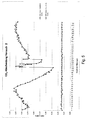
- the SO 2 and the CO 2 content of the exhaust gases was as in the Fig. 1 each measured at the inlet and at the outlet of the reactor.
- the measurements were made every 30 seconds and were recorded on the Figures 2 and 3 shown graphically.
- the first measurements shown here were made after saturation of the catalyst, ie 40 hours after start-up of the reactor.
- the CO 2 concentration was varied several times between 1.0% by volume and 1.55% by volume and it was found that the CO 2 purification values were on average less than 60%.
- the test run was continuous over about 40 minutes. Over this entire period The treated exhaust gases contained no more SO 2 , as from the Fig. 3 is apparent.
- the reactor is made of glass fiber reinforced plastic and has a volume of about 2 m 3 . and is filled with 0.3 m 3 of Norit_PK_2-4 type catalyst.
- the SO 2 and the CO 2 content of the exhaust gases was as in the Fig. 1 each measured at the inlet and at the outlet of the reactor. The measurements were made every 30 seconds and were recorded on the FIGS. 4 and 5 shown graphically. The first measurements shown here were made after saturation of the catalyst, ie 40 hours after start-up of the reactor. The CO 2 concentration was varied several times between 0.8% by volume and 0.3% by volume and it was found that the CO 2 purification values of more than 85% were achieved. The test trial ran continuously over about 2 hours. At the same time, a near 100% conversion of SO 2 was achieved over this entire period, as shown in the Fig. 3 is apparent.
Landscapes
- Chemical & Material Sciences (AREA)
- Engineering & Computer Science (AREA)
- General Chemical & Material Sciences (AREA)
- Environmental & Geological Engineering (AREA)
- Analytical Chemistry (AREA)
- Oil, Petroleum & Natural Gas (AREA)
- Chemical Kinetics & Catalysis (AREA)
- Biomedical Technology (AREA)
- Health & Medical Sciences (AREA)
- Life Sciences & Earth Sciences (AREA)
- Sustainable Development (AREA)
- Exhaust Gas Treatment By Means Of Catalyst (AREA)
- Catalysts (AREA)
- Treating Waste Gases (AREA)
- Carbon And Carbon Compounds (AREA)
Description
- Die vorliegende Erfindung betrifft allgemein ein Verfahren zur katalytischen Entfernung von Kohlendioxyd und Schwefeldioxid aus Abgasen.
- Die Diskussionen über den Klimawandel haben der Menschheit deutlich vor Augen geführt, dass die Ressourcen, die ihr zu Verfügung stehen, begrenzt sind und dass die durch menschliche Tätigkeiten entstandenen Schadstoffe einen großen Impakt auf die Umwelt haben und das Klima nachhaltig verändern. Nachdem in den siebziger Jahren des zwanzigsten Jahrhunderts die Schwefelemissionen im Mittelpunkt standen, sind jetzt die Kohlendioxydemissionen zum zentralen Thema geworden. Seit einigen Jahren wird intensiv nach Möglichkeiten gesucht, die Entstehung dieses Gas möglichst zu vermeiden oder aber aus der Atmosphäre zu entfernen. Zu dieser letzten Möglichkeit wurden verschiedene Verfahren vorgeschlagen das Kohlendioxyd aus der Atmosphäre an Feststoffe oder Flüssigkeiten zu binden und dann zu lagern. Solche Verfahren sind zum Beispiel aus der
W02005108297A ,KR200502862 A W02004098740 A bekannt. Es wurde auch versucht das Kohlendioxyd elektrochemisch zu reduzieren, wobei die elektrische Energie wie in derJP4063115 A - Diese Verfahren haben jedoch den Nachteil, dass sie entweder das Problem nur verlagern oder aber sehr energieintensiv sind.
- Eine Aufgabe der vorliegenden Erfindung ist es, ein Verfahren bereit zu stellen, das Kohlendioxyd aus Abgasen entfernt.
- Diese Aufgabe wird erfindungsgemäß gelöst, durch ein Verfahren zur katalytischen Entfernung von Kohlendioxyd und Schwefeldioxid aus Abgasen in einem, mit einem Aktivkohlekatalysator beaufschlagten Reaktor, gekennzeichnet durch die folgenden Schritte:
- Sättigung der Aktivkohle mit SO2,
- Sättigung oder Teilsättigung der Abgase mit Wasser,
- Einführung der Abgase in den Reaktor,
- katalytische Umwandlung des SO2 zu H2SO4 und parallel dazu die katalytische Umwandlung am selben Katalysator von CO2 in C und O2 und/oder eine Anlagerung von C an Schwefelverbindungen.
- Auswaschen des Katalysators und Austragen des H2SO4 als Flüssigkeit und C als Feststoff oder/und an Schwefelverbindungen gebunden.
- Ein Vorteil des Verfahrens besteht darin, dass die Reaktionsprodukte H2SO4 und C aus der Gasphase der Abgase entzogen werden und nach dem Verfahren als Flüssigkeit (H2SO4) bzw. als Feststoff (C bzw. C an Schwefelverbindungen) vorliegen und weiter verwendet werden können.
- Das Verfahren erlaubt es, Abgase aus industriellen Anlagen zu behandeln, die Kohlendioxyd und SO2 enthalten und diese beiden Schadstoffe gleichzeitig und parallel, also in einem Verfahren ganz bzw. zu einem erheblichen Teil aus den Abgasen zu entfernen.
- Bei dem Verfahren wird mindestens 40% des in den Abgasen enthaltenen CO2 umgewandelt, bevorzugt mindestens 50%, besonders bevorzugt mindestens 60% und insbesondere mindestens 82%.
- Unter Schwefel-Kohlenstoffverbindungen versteht man im Zusammenhang mit der vorliegenden Erfindung Verbindungen die sowohl Schwefel also auch Kohlenstoff enthalten und zwar unabhängig von der Anzahl, der Oxidationsstufe und der Präsenz von anderen Elementen.
- Unter dem Begriff Sättigung der Aktivkohle mit SO2/SO3 versteht man im Zusammenhang mit der vorliegenden Erfindung, dass der Aktivkohlekatalysator über genügend exotherme Umwandlungsenergie verfügt welche durch die SO2/SO3/H2SO4 Umwandlung erfolgt um anschliessend mit der CO2-Umwandlung zu beginnen. Dies entspricht wie aus unseren Versuchen hervorging einer Grössenordnung von 20-50 kg SO2/m3 Katalysator.
- Unter dem Begriff Sättigung der Abgase mit Wasser versteht man im Zusammenhang mit der vorliegenden Erfindung ein Einbringen von feinsten Wassertröpfchen ins Rauchgas welches eine Erniedrigung der Temperatur und eine Zunahme vom Wassergehalt bis zu einer relativen Luftfeuchtigkeit von max 100% im Rauchgas ergibt. Diese Sättigung der Abgase mit Wasser wird bevorzugter Weise in einem Quenchkühler oder Einspritzkühler vorgenommen. Der pH-Wert dieses Wassers kann entweder neutral, basisch oder sauer sein. Der pH-Wert des zur Sättigung der Abgase benutzten Wassers liegt bevorzugter Weise zwischen 3 und 11 und besonders bevorzugt zwischen 5 und 9.
- Dieses Verfahren hat eine gewisse Ähnlichkeit mit dem sogenannten SULFACID Verfahren, bei dem SO2 auf einem Aktivkohlekatalysator in H2SO4 umgewandelt wird. Bei diesem Verfahren wird das Kohlendioxyd jedoch nicht in Kohlenstoff und Sauerstoff resp. in Schwefelkohlenstoffverbindungen umgewandelt, da bei diesem Verfahren die erzeugte exotherme Energie bei der Umwandlung von SO2 über SO3 zu H2SO4 fast komplett an die wässrige Umhüllung im Katalysatorbett abgegeben wird.
- Durch die Versuche, die im Zusammenhang mit der Forschung die zu dieser Erfindung geführt haben, gemacht wurden, wurde festgestellt, dass bei allen möglichen konventionellen Fahrweisen vom SULFACID Verfahren keine Abscheidung von CO2 festgestellt wurde, weder in den Versuchen noch in den industriellen Anwendungen da in diesem Fall die exotherme Energie die bei der Umsetzung von SO2 über SO3 zu H2SO4 erzeugt wird an die wässrige Umhüllung im Bett abgegeben wird, um somit o.g. H2SO4 Säure zu erzeugen.
- Vorzugsweise werden Abgase behandelt bei denen das Verhältnis von CO2 zu SO2 zwischen 0,25 mol/mol und 0,58 mol/mol liegt. Selbstverständlich ist es auch möglich Abgase zu behandeln, in denen das Verhältnis der beiden Schadstoffe außerhalb dieser Spanne liegt. In einem solchen Fall wird jedoch der Schadstoff, der über der oben angegebenen Grenze liegt, nicht vollständig, sondern nur teilweise aus den Abgasen entfernt.
- Die Eingangstemperaturen der Abgase liegen vorzugsweise zwischen der Umgebungstemperatur und 150 °C. Höhere Temperaturen im Dauerbetrieb könnten den Katalysator auf Dauer schädigen.
- Der Sauerstoffgehalt der Abgase ist eigentlich nicht kritisch, er sollte jedoch idealerweise mindestens 5 Vol.% betragen. Bevorzugterweise sollte der O2-Gehalt mehr als 8 mal höher als der SO2-Gehalt liegen.
- Die Sättigung der Abgase mit Wasser kann ganz einfach durch Quenchen oder ein ähnliches Verfahren durchgeführt werden. Die Abgase sollten natürlich sowenig wie möglich Feststoffe, Staub und ähnliches enthalten um eine Vergiftung und Zusetzung des Katalysators zu verhindern. Dieses Entstauben der Abgase wird durch konventionelle Filteranlagen erreicht, bevor die Abgase dann in die Quenche geleitet werden.
- Der Abreinigungsfaktor für SO2 der Abgase mit Hilfe des Katalysators liegt bevozugterweise zwischen 0,4 und 0,6. Es werden demnach zwischen 40% und 60% des SO2 über SO3 in H2SO4 umgewandelt, der Rest des SO2/SO3 reagiert zu Schwefelkohlenstoffverbindunden resp. wird in Form von SO2/SO3 in die Abluft abgegeben. Beispiel: Bei einer 100%-igen Abscheidung von SO2 im CO2-Prozess entspricht dies einer Umwandlung von 40-60% in H2SO4 sowie einer 60-40%-igen Umwandlung in Schwefelkohlenstoffverbindungen (bei einer Überbelastung mit SO2/SO3 erfolgt demnach keine 40-60%-ige Umsetzung in H2SO4 wobei dann der Überschuss in Form von SO2/SO3 in die Abluft abgegeben wird - in diesem Fall wird auch die CO2 Abscheidung reduziert resp. kommt zum Erliegen). Im SULFACID Prozess wird bei einer 100%-igen Abscheidung von SO2 eine 70-90%-ige Umsetzung in H2SO4 erfolgen sowie eine ca. 30-10% Freigabe von SO2/SO3 in die Abluft. Bei einer Überbelastung mit SO2 /SO3 im SULFACID Prozess wird die 70-90%-ige Umsetzung in H2SO4 nicht vergrößert sondern der Überschuss geht in Form SO2/SO3 auch wieder in Abgase ein.
- Folglich können im erfindungsgemäßen Verfahren bei großen Volumenströmen und/oder hohen Konzentrationen an SO2/SO3/CO2 mehrere Reaktoren parallel und/oder seriell geschaltet werden um geforderte Werte zu erreichen.
- Weitere Einzelheiten und Vorteile der Erfindung können der nachfolgenden ausführlichen Beschreibung einer möglichen Ausführungsform der Erfindung anhand der beiliegenden
Figur 1 entnommen werden. Diese zeigt: -
Fig. 1 eine schematische Darstellung der Versuchsanordnung, -
Fig. 2 eine graphische Darstellung der bei Versuch 1 gemessenen Werte vom SO2-Gehalt der Abgase am Eintritt bzw. Austritt des Reaktors, -
Fig. 3 eine graphische Darstellung der bei Versuch 1 gemessenen Werte vom CO2-Gehalt der Abgase am Eintritt bzw. Austritt des Reaktors, -
Fig. 4 eine graphische Darstellung der bei Versuch 2 gemessenen Werte vom SO2 -Gehalt der Abgase am Eintritt bzw. Austritt des Reaktors, -
Fig. 5 eine graphische Darstellung der bei Versuch 2 gemessenen Werte vom CO2-Gehalt der Abgase am Eintritt bzw. Austritt des Reaktors. - Die in der
Figur 1 , zur Illustration der Erfindung, gezeigte Versuchsanordnung umfasst einen Versuchsreaktor 10, in dessen unteren Teil 12, ein Versuchsgas zugeführt wird und in dessen oberen Teil 14 Wasser aufgesprüht wird. - Das Versuchsgas, das benutzt wurde, um die Abgase zu simulieren, besteht aus Umgebungsluft welche in einem Heizgerät 16 auf ca. 80 °C aufgeheizt wird und dem anschließend SO2 aus einer ersten Druckflasche 18 und CO2 aus einer zweiten Druckflasche 20 über entsprechende Ventile 22, 24 zudosiert wird. Ein erstes Messgerät 26 analysiert die Zusammensetzung (SO2- Gehalt, CO2-Gehalt, O2-Gehalt), die Temperatur, die Durchflussmenge und die Durchflussgeschwindigkeit des Versuchsgases.
- Das Versuchsgas wird dann in einer Quenche 28 durch Verdampfen von Wasser auf Sättigungstemperatur abgekühlt. Das Versuchsgas wird von einem Abgasgebläse 30 über die Quenche 28 in den Versuchsreaktor 10 gesaugt. Ein Tropfenabscheider am Austritt der Quenche 28 sorgt für die Sprühabscheidung.
- Das Versuchsgas durchströmt den Versuchsreaktor 10 und den sich darin befindenden Aktivkohlekatalysator 32 von unten nach oben und wird nach Austritt aus dem Versuchsreaktor 10 in einem zweiten Messgerät 34 auf die selben Parameter wie bei dem ersten Messgerät 26, d.h. Zusammensetzung (SO2-Gehalt, CO2-Gehalt, O2-Gehalt), die Temperatur, die Durchflussmenge und die Durchflussgeschwindigkeit, geprüft und anschließend in die Atmosphäre abgegeben.
- Das in dem Prozess benötigte Wasser wird aus einem Vorratsbehälter 36 über ein Dossiergerät 38, wo der Durchfluss gemessen wird und eine Pumpe 40 in den oberen Teil 14 des Versuchsreaktors 10 geleitet, wo das Wasser den Aktivkohlekatalysator 32 im Gegenstrom zu dem Versuchsgas durchfließt. Das für die Quenche 28 benötigte Wasser kommt direkt aus der Wasserversorgung und wird im Kreislauf gefahren.
- Alternativ kann das in dem Prozess benötigte Wasser aber auch im Gleichstrom d.h. in der selben Richtung wie das Versuchsgas durch den Reaktor geleitet werden. Ob ein Gleichstrom- oder ein Gegenstromevrfahren gewählt wird, hängt z.B. von den örtlichen Begebenheiten ab.
- Am Aktivkohlekatalysator, welcher nicht zusätzlich mit Metallen imprägniert ist, wird das SO2 katalytisch in SO3 und anschließend in Falle von Wasserzugabe in Schwefelsäure umgewandelt. Die eingesetzten Füllkörper, unterhalb des Molekularsiebes befindlich, die zum Verteilen des Gases dienen und können dotiert sein. Die gebildete Schwefelsäure und der Kohlenstoff resp. Schwefel-Kohlenstoffverbindungen werden von dem Aktivkohlekatalysator durch taktweises Besprühen mit Wasser, in Abhängigkeit von Volumen des Katalysators and der SO2/SO3 Konzentration, im Gegenstrom zum Gas, abgespült. Im Falle der Pilotanlage wurde 1-4 mal/Stunde bedüst mit einer Wassermenge von 2-15 I/Stunde. Die Menge an Wasser die gebraucht wird, richtet sich nach der gewünschten Konzentration an Schwefelsäure die jedoch üblicherweise zwischen 5-25 Gew-% liegt. Im unteren Teil 12 des Versuchsreaktors 10 wird das Wasser zusammen mit der im Prozess entstandenen, wässrigen Schwefelsäurelösung und der darin suspendierte Kohlenstoff resp. Kohlenstoff-Schwefelverbindungen in einem Behälter 42 aufgefangen und der Säuregehalt wird mittels eines Messgeräts 44 bestimmt. Anschließend wird die Schwefelsäurelösung durch eine Pumpe 46 abgepumpt und die Durchflussmenge wird mit einem weiteren Messgerät 48 festgestellt.
- In der beschriebenen Anlage wird das Schwefeldioxid der Abgase katalytisch an feuchten Katalysatorenkörnern über SO3 zu Schwefelsäure umgewandelt, und gleichzeitig bzw. parallel wird Kohlendioxid zu Kohlenstoff und Sauerstoff aufgespalten. Ein Teil des Kohlenstoffs wird jedoch auch an Schwefelverbindungen angelagert.
- Das Verfahren wurde unter folgenden Bedingungen erfolgreich getestet:
- Wassersättigung der Abgase vor Eintritt in den Reaktor durch Quenchen.
- SO2 Gehalt der Rauchgase zwischen 300 ppm und 6000 ppm. Hierbei sei bemerkt dass im Idealfall und im kontinuierlichen Betrieb nur 174 bis 3480 ppm von diesem SO2 bei der CO2-Umwandlung umgesetzt werden können. Der Überschuss an SO2 wird in diesem Fall für die H2SO4 Säurebildung benutzt resp. in Form SO2/SO3 in die Atmosphäre abgegeben.
- CO2 Gehalt der Rauchgase zwischen 0,1 Vol.% (1000 ppm) und 15 Vol.% (150 000 ppm).
- Gastemperatur zischen 10 und 80°C.
- O2-Gehalt etwa 20 Vol%
- Wassersättigung und Kühlung der Abgase durch Quenchen
- Getestete Katalysatoren wurden von der Firma NORIT Nederland B.V. aus Postbus 105 NL-3800 AC Amersfoort unter den Bezeichnungen Norit_PK1-3, Norit_PK_2-4und Norit_PK_3-5 zur Verfügung gestellt.
- Bei diesen Katalysatoren handelt es sich um ein Aktivkohlegranulat, mit einer Körnung zwischen 1-3 mm; 2-4 mm bzw. 3-5 mm und durch Dampfaktivierung hergestellt wurde. Folgende allgemeine Eigenschaften werden vom Hersteller zugesichert: Jodzahl 800; Methylenblauadsorption 11 g/100 g; Innere Oberfläche (B.E.T) 875 m2/g; Schüttdichte 260 kg/m3; Dichte nach Rückspülen 230 kg/m3; Gleichförmigkeitsgrad 1,3 - Aschegehalt 7 Gew.-%; pH alkaline; Feuchte (verpackt) 2 Gew.-%
- Bei den Versuchen wurden Rauchgasanalysegeräte der Marke Testo verwendet. Die Geräte sind neuester Generation (Baujahr 2009) und wurden vom Hersteller kalibriert. Außerdem wurden bei den Versuchen die Analysedaten dieser Rauchgasanalysegeräte mit parallel durchgeführten nasschemischen Messungen bestätigt. Die Ergebnisse lagen für alle Messungen in den zulässigen Abweichungstoleranzen.
- Der Ablauf der SO2-Umsetzung nach H2SO4 auf der Katalysatoroberfläche verläuft formal nach der Summenformel:
SO2 + ½ O2 + n H2O (katalytisch)→ H2SO4 + (n-1) H2O
- Ohne sich auf eine Theorie festlegen zu wollen, wird angenommen, dass:
- O2 und SO2 zu den aktiven Zentren des Katalysators wandert und hier zu SO3 umgewandelt wird.
- SO3 aus den aktiven Zentren des Katalysators heraus wandert und mit der wässrigen Umhüllung um das Katalysatorkorn H2SO4 bildet.
- SO2 mit Sauerstoff und Wasser unter Bildung von Schwefelsäure gemäß vorstehender Reaktionsgleichung reagiert,
- das CO2 Molekül, das ungefähr die gleiche Größe hat wie ein SO2 Molekül ebenfalls in die Poren des Katalysatorkorns transportiert wird und dort durch zuführen der Bildungsenergien getrennt resp. an Schwefelverbindungen adsorbiert wird Die konzentrierte Schwefelsäure welche sich in der wässrigen Hülle um das Korn bildet adsorbiert durch hohe Oberflächenspannungen (spezifische Oberfläche) den C-Anteil von CO2 und O2. Es entstehen sogenannte Kohlenstoff-Schwefelverbindungen.
- der an einer Schwefelverbindung befindliche C-Teil innerhalb der Schwefelsäure als Suspension vorhanden ist,
- der Austrag der gebildeten Kohlenstoffverbindungen in einer Suspension mit der Schwefelsäure aus dem Katalysator durch Waschen mit Wasser erfolgt, wobei die Schwefelsäure verdünnt wird. Der gebildeten Kohlenstoffverbindungen fallen nach kurzer Zeit aus.
- Zum Waschen des Katalysators kann enthärtetes bzw. entsalztes Wasser verwendet werden.
- Es wird angenommen, ohne sich jedoch auf eine Theorie festlegen zu wollen, dass die Adsorption von CO2 durch die Ausnutzung der thermischen Energie, die durch die Oxidation von SO2 zu SO3 und/oder bei der Bildung der Schwefelsäure (SO3- H2SO4) erzeugt wird erfolgt. Die exotherme Energie, die bei der Oxidation freigesetzt wird beträgt ΔHR= - 98,77 kJ/mol, bei der Bildung der Schwefelsäure beträgt diese ΔHR= - 132,23 kJ/mol; insgesamt steht also eine exotherme Energie von ΔHR Gesamt= - 231 kJ/mol zur Verfügung. Die Energie von + 394,4 kJ/mol, die zum Umwandeln von CO2 benötigt wird, kann aus einer exothermen Reaktion, von SO2 zu SO3, bezogen werden oder es kann aus den zwei exothermen Reaktionen, SO2 zu SO3 zu H2SO4, bezogen werden. Dies bedeutet, dass eine exotherme Energie zwischen -98,77 kJ/mol und -231 kJ/mol zur Verfügung steht.
- Im Idealfall, d.h. ohne Energieverluste, kann man dementsprechend bei der Oxidation zu SO3 pro Mol SO2 also 0,25 Mol CO2 umsetzen. Wird jedoch zusätzlich Säure erzeugt, so kann im Idealfall pro Mol SO2 0,58 mol CO2 umgesetzt werden, bzw. pro kg SO2 0.39kg CO2 umsetzen und gleichzeitig 1.53 kg H2SO4 erzeugen. Man muss jedoch berücksichtigen dass auch noch andere Reaktionen stattfinden (können) sowie z.B die oben beschriebene Bildung von Schwefel-Kohlenstoffverbindungen.
- Die oben genannten Reaktionen der CO2 Abscheidung kann erst nach Erreichen eines gewissen Sättigungsgrades mit SO2 in den Poren des Katalysators in Bezug auf die Schwefelsäurebildung ablaufen. Dieses Gleichgewicht tritt im Reaktor auf, nachdem genug SO2 zu SO3 umgesetzt worden ist und beginnt Schwefelsäure zu bilden. Ein solcher Zustand stellt sich je nach Fahrweise (SO2/SO3 Aufgabemenge) nach ca. 20 bis 100 Betriebsstunden ein. Dieser Zustand ist von der %-Gew. Säurebildung unabhängig. Aus diesem Grund kann dieser Prozess auch bei verschiedenen %-Gew. (H2SO4) Säuren ablaufen. Beispiel: Bei einer 100%-ige Abscheidung von SO2 im CO2-Prozess entspricht dies einer Umwandlung von 40-60% von SO2 in H2SO4 und sowie 60-40% von SO2 in Schwefelkohlenstoffverbindungen.
- Die Versuche wurden folgenden Bedingungen durchgeführt:
Rohgasvolumenstrom min. 200 m3/h max. 300 m3/h CO2-Gehalt (Eintritt) Min 0,20 Vol-% max 1,50 Vol-% SO2-Gehalt (Eintritt) min. 300 ppm max. 4.500 ppm Temperatur Abgas Min. 10 °C Max. 12 °C Taupunkttemperatur Gesättigt O2-Gehalt >20 Vol-% - Der Reaktor ist aus glasfaserverstärktem Kunststoff, hat ein Volumen von ca 2 m3 und ist mit 1 m3 eines Aktivkohlekatalysators vom Typ Norit_PK_2-4 befüllt.
- In einer ersten Phase wurde die Versuchsanlage ca 50 Stunden unter Zugabe von SO2 aus Gasflaschen gefahren, hierbei wurde zwischen 3.000-4.000 ppm SO2 aufgegeben. Insgesamt wurde der Reaktor mit ca. 45 kg SO2 (ca. 45 kg SO2/m3 Katalysator) beladen. Gemäß diesem Test erfolgte die Wasseraufgabe von 2 bis 15 I/Stunde in aufgeteilt in 1 bis 4 Portionen/Stunde. Hierbei wurde entgegen dem SULFACID Prozess keine nennenswerte Schwefelsäure Konzentration erreicht (4-6 Gew-%). Nach ca. 40 Stunden (ca. 36 kg SO2/m3 Katalysator) gelang die Abreinigung von CO2. Der SO2 und der CO2 Gehalt der Abgase wurde wie in der
Fig. 1 dargestellt jeweils am Eintritt und am Austritt des Reaktors gemessen. Die Messungen erfolgten alle 30 Sekunden und wurden auf denFiguren 2 und3 graphisch dargestellt. Die ersten, hier dargestellten Messungen erfolgten nach Sättigung des Katalysators d.h. 40 Stunden nach Inbetriebnahme des Reaktors. Die CO2 Konzentration wurde zwischen 1,0 Vol % und 1,55 Vol% mehrfach variiert und es wurde festgestellt dass die Abreinigungswerte von CO2 im Schnitt kleiner als 60% waren. Der Testversuch verlief kontinuierlich über ca. 40 Minuten. Über diesen gesamten Zeitraum enthielten die behandelten Abgase kein SO2 mehr, wie aus derFig. 3 ersichtlich ist. - Bei einer Überbeladung des Akitvkohlekatalysators mit SO2 kann die CO2-Umsetzung entweder nur teilweise oder gar nicht stattfinden. Auch sollte dem Verfahren nicht zu viel Wasser zugegeben werden da sonst die Umwandlung von CO2 verringert wird zu Gunsten von einer H2SO4 Umwandlung oder vermehrt SO2/SO3 in die Abluft gegeben wird. Hierzu sei bemerkt, dass bei einem klassischen SULFACID Prozess sehr viel größere Mengen an Wasser zugegeben werden. Als Beispiel würden bei einem vergleichbaren SULFACID Prozess regelmäßig alle 15 Minuten ca. 8-10 Liter aufgegeben (32-40 I/Stunde/m3 Katalysator). Im Gegensatz dazu wird beim CO2 Prozess jede Stunde maximal 15 Liter (in der Regel eher 8 Liter) in unregelmässigen Abständen aufgegeben.
-
Rohgasvolumenstrom min. 200 m3/h max. 300 m3/h CO2-Gehalt Min 0,30 Vol-% Max 1,00 Vol-% SO2-Gehalt (Eintritt) min. 300 ppm max. 500 ppm Temperatur Abgas Min. 70 °C Max. 80 °C Taupunkttemperatur Gesättigt O2-Gehalt >20 Vol-% - Der Reaktor ist aus glasfaserverstärktem Kunststoff und hat ein Volumen von ca. 2 m3. und ist mit 0,3 m3 eines Katalysators vom Typ Norit_PK_2-4 befüllt.
- In einer ersten Phase wurde die Versuchslage ca 50 Stunden unter Zugabe von SO2 aus Gasflaschen gefahren, hierbei wurde zwischen 300-500 ppm SO2 wegen der geringeren Katalysatorfüllung aufgegeben. Insgesamt wurde der Reaktor mit ca. 15 kg SO2 beladen (ca. 50 kg SO2/m3 Katalysator). Gemäß diesem Test erfolgte die Wasseraufgabe antizyklisch. In 1 bis 4 Portionen/Stunde wurden zwischen 2 und 5 l/ Stunde aufgegeben d.h. 6.6 bis 16.6 I/Stunde/m3 Katalysator. Hierbei wurde entgegen dem Sulfacid Prozess keine nennenswerte Konzentration an Schwefelsäure erreicht (1-2 Gew-%). Erst nach ca. 40 Stunden (ca. 40 kg SO2/m3 Katalysator gelang die Abreinigung von CO2. Der SO2 und der CO2 Gehalt der Abgase wurde wie in der
Fig. 1 dargestellt jeweils am Eintritt und am Austritt des Reaktors gemessen. Die Messungen erfolgten alle 30 Sekunden und wurden auf denFiguren 4 und5 graphisch dargestellt. Die ersten, hier dargestellten Messungen erfolgten nach Sättigung des Katalysators d.h. 40 Stunden nach Inbetriebnahme des Reaktors. Die CO2 Konzentration wurde zwischen 0.8 Vol % und 0.3 Vol% mehrfach variiert und es wurde festgestellt dass die Abreinigungswerte von CO2 von über 85 % erreicht wurden. Der Testversuch verlief kontinuierlich über ca. 2 Stunden. Über diesen gesamten Zeitraum wurde gleichzeitig eine nahe 100 %-ige Umwandlung von SO2 erreicht, wie aus derFig. 3 ersichtlich ist. - Die Versuche, die im Zusammenhang mit dieser Erfindung durchgeführt wurden, haben ergeben, dass ein gewisser Sättigungsgrad des Katalysators mit SO2 vorhanden sein muss um ein Starten der CO2 Abscheidung zu erreichen (siehe Versuche) ).Bis zum Erreichen dieses Sättigungsgrades läuft die CO2 Abscheidung gar nicht oder teilweise mit einer geringeren Abscheideleistung wie in Versuch 1. Es wird angenommen, dass die hierbei adsorbierte Menge an O2 in positiver Weise die SO2/SO3 Umsetzung in H2SO4 beeinträchtigt, sodass auch weniger SO2/SO3 aus dem Reaktor abgegeben wird ggf. höhere Mengen an SO2/SO3 abgeschieden werden können. Im Gegensatz zum SULFACID Prozess wird die exotherme Energie ausgenutzt um das CO2 zu trennen und wird nicht an die wässrige Umhüllung im Bett abgegeben.
- Ein wichtiges Kriterium CO2 abscheiden zu können liegt im Abreinigungsfaktor von SO2 des Katalysators. Bei einem normalen kontinuierlichen Betrieb für SO2-Umwandlung in H2SO4 (in SULFACID-Betrieb) liegt er bei 0,7 und 0,9. Dieser Tatsache bedingt erfolgt auch eine Säurekonzentration von 10-15 Gew-%. Für CO2-Abscheidung ist der SO2 Abreinigungsfaktor des Katalysators geringer. Aus den Testversuchen hat sich hier eine SO2-Umwandlung in H2SO4 von 0,4 und 0,6 ergeben welches darauf hindeutet, dass etwa 40-60% vom SO2 in H2SO4 umgesetzt werden. Dies bestätigt auch die Tatsache, dass die Säurekonzentration in diesen Fällen zwischen 1 und 6 Gew-% liegt.
-
- 10
- Versuchsreaktor
- 12
- unteren Teil
- 14
- oberen Teil
- 16
- Heizgerät
- 18,20
- Druckflasche
- 22,24
- Ventile
- 26
- erstes Messgerät
- 28
- Quenche
- 30
- Abgasgebläse
- 32
- Aktivkohlekatalysator
- 34
- zweiten Messgerät
- 36
- Vorratsbehälter
- 38
- Dossiergerät
- 40
- Pumpe
- 42
- Behälter
- 44
- Messgeräts
- 46
- Pumpe
- 48
- Messgerät
CO2 + SO2 + H2O → C + H2SO4 + ½ O2
H2SO4 + CO2 → SCO3 + H2O + O2
Claims (9)
- Verfahren zur katalytischen Entfernung von Schwefeldioxid und Kohlendioxyd aus Abgasen in einem, mit einem Aktivkohlekatalysator beaufschlagten Reaktor, gekennzeichnet, durch die folgenden Schritte:• Sättigung der Aktivkohle mit SO2,• Sättigung oder Teilsättigung der Abgase mit Wasser,• Einführung der Abgase in den Reaktor,• katalytische Umwandlung des SO2 in H2SO4 und parallel dazu die katalytische Umwandlung am selben Katalysator von CO2 in C und O2 sowie in Schwefel-Kohlenstoffverbindungen.• Auswaschen des Katalysators und Austragen des H2SO4 als Flüssigkeit und des C als Feststoff und/oder an Schwefelverbindungen gebunden.
- Verfahren nach Anspruch 1, dadurch gekennzeichnet, dass das Verhältnis von SO2 und CO2 in den Abgasen zwischen 0,25 und 0,58 mol/mol liegt.
- Verfahren nach Anspruch 1 oder 2, dadurch gekennzeichnet, dass die Eingangstemperatur der Abgase zwischen der Umgebungstemperatur und 150° C liegt.
- Verfahren nach einem der Ansprüche 1 bis 3, dadurch gekennzeichnet, dass der O2-Gehalt der Abgase mindestens 5 Vol.% beträgt.
- Verfahren nach einem der Ansprüche 1 bis 4, dadurch gekennzeichnet, dass der O2-Gehalt mehr als 8 mal höher als der SO2-Gehalt liegt.
- Verfahren nach einem der Ansprüche 1 bis 5, dadurch gekennzeichnet, dass die Sättigung der Abgase mit Wasser durch Quenchen erfolgt.
- Verfahren nach einem der Ansprüche 1 bis 6, dadurch gekennzeichnet, dass enthärtetes oder entsalztes Wasser zum Auswaschen des Katalysators verwendet wird.
- Verfahren nach einem der Ansprüche 1 bis 7, dadurch gekennzeichnet, dass das Auswaschen des Katalysators im Gleichstrom oder im Gegenstrom zu den Abgasen erfolgt.
- Verfahren nach einem der Ansprüche 1 bis 8, dadurch gekennzeichnet, dass der SO2 Abreinigungsfaktor des Katalysators zwischen 0,4 und 0,6 liegt.
Priority Applications (1)
| Application Number | Priority Date | Filing Date | Title |
|---|---|---|---|
| PL11720737T PL2566603T3 (pl) | 2010-05-07 | 2011-05-06 | Sposób katalitycznego usuwania dwutlenku węgla i dwutlenku siarki z gazów odlotowych |
Applications Claiming Priority (2)
| Application Number | Priority Date | Filing Date | Title |
|---|---|---|---|
| LU91685A LU91685B1 (de) | 2010-05-07 | 2010-05-07 | Verfahren zur katalytischen Entfernung von Kohlendioxyd und Schwefeldioxid aus Abgasen |
| PCT/EP2011/057271 WO2011138425A1 (de) | 2010-05-07 | 2011-05-06 | Verfahren zur katalytischen entfernung von kohlendioxid und schwefeldioxid aus abgasen |
Publications (2)
| Publication Number | Publication Date |
|---|---|
| EP2566603A1 EP2566603A1 (de) | 2013-03-13 |
| EP2566603B1 true EP2566603B1 (de) | 2014-03-12 |
Family
ID=42245615
Family Applications (1)
| Application Number | Title | Priority Date | Filing Date |
|---|---|---|---|
| EP11720737.3A Active EP2566603B1 (de) | 2010-05-07 | 2011-05-06 | Verfahren zur katalytischen entfernung von kohlendioxid und schwefeldioxid aus abgasen |
Country Status (23)
| Country | Link |
|---|---|
| US (1) | US8535631B2 (de) |
| EP (1) | EP2566603B1 (de) |
| JP (3) | JP2013525107A (de) |
| KR (1) | KR20130084979A (de) |
| CN (1) | CN102892484B (de) |
| AR (1) | AR081013A1 (de) |
| AU (1) | AU2011249726B2 (de) |
| BR (1) | BR112012028256A2 (de) |
| CA (1) | CA2797144C (de) |
| CL (1) | CL2012003099A1 (de) |
| DK (1) | DK2566603T3 (de) |
| EA (1) | EA021534B1 (de) |
| ES (1) | ES2471882T3 (de) |
| LU (1) | LU91685B1 (de) |
| MA (1) | MA34257B1 (de) |
| MX (1) | MX2012012878A (de) |
| PL (1) | PL2566603T3 (de) |
| SG (1) | SG185469A1 (de) |
| TN (1) | TN2012000519A1 (de) |
| TW (1) | TWI510282B (de) |
| UY (1) | UY33371A (de) |
| WO (1) | WO2011138425A1 (de) |
| ZA (1) | ZA201208968B (de) |
Families Citing this family (10)
| Publication number | Priority date | Publication date | Assignee | Title |
|---|---|---|---|---|
| LU91900B1 (de) * | 2011-11-14 | 2013-05-15 | Carbon Process & Plant Engineering S A | Verfahren zur katalytischen Entfernung von Kohlendioxyd NOx aus Abgasen |
| US8877152B2 (en) * | 2013-02-27 | 2014-11-04 | Alstom Technology Ltd | Oxidation system and method for cleaning waste combustion flue gas |
| LU92547B1 (de) * | 2014-09-17 | 2016-03-18 | Cppe Carbon Process & Plant Engineering S A | Verfahren zur katalytischen entfernung von schwefeldioxid aus abgasen |
| TWI569866B (zh) * | 2015-04-07 | 2017-02-11 | 中國鋼鐵股份有限公司 | 自動化二氧化碳吸收裝置及其方法 |
| LU93014B1 (en) * | 2016-04-04 | 2017-10-05 | Ajo Ind S A R L | Catalyst mixture for the treatment of waste gas |
| LU93013B1 (en) | 2016-04-04 | 2017-11-08 | Cppe Carbon Process & Plant Eng S A En Abrege Cppe S A | Process for the removal of heavy metals from fluids |
| LU93012B1 (en) | 2016-04-04 | 2017-11-08 | Cppe Carbon Process & Plant Eng S A En Abrege Cppe S A | Sulfur dioxide removal from waste gas |
| CN107326390B (zh) * | 2017-06-09 | 2019-03-26 | 中国矿业大学 | 一种阳极氧化强化二氧化碳还原的装置及其方法 |
| LU100469B1 (en) * | 2017-10-09 | 2019-04-09 | Cppe Carbon Process & Plant Eng S A | Elimination of SO2 and CO2 from a gas |
| KR102671784B1 (ko) * | 2021-10-01 | 2024-06-03 | 주식회사 에코프로에이치엔 | 케미컬 필터의 재사용 방법 |
Family Cites Families (24)
| Publication number | Priority date | Publication date | Assignee | Title |
|---|---|---|---|---|
| US3862295A (en) * | 1972-06-30 | 1975-01-21 | Westvaco Corp | Method for sorptive removal of sulfur gases |
| US4140752A (en) * | 1977-07-25 | 1979-02-20 | Allied Chemical Corporation | Process for removing sulfur dioxide from waste gases |
| US4259304A (en) * | 1979-09-07 | 1981-03-31 | Foster Wheeler Energy Corporation | Activation of coal |
| US4477426A (en) * | 1983-04-29 | 1984-10-16 | Foster Wheeler Energy Corporation | Process for preparing a sulfur dioxide containing gas stream for reaction with coal |
| EP0431819A1 (de) * | 1989-11-28 | 1991-06-12 | Yutaka Tamaura | Methode zur Zersetzung von gasförmigen Oxiden und dafür benutzter Katalysator |
| JPH0463115A (ja) | 1990-06-28 | 1992-02-28 | Hitachi Ltd | 炭酸ガスの光還元電極および還元装置 |
| US6114273A (en) * | 1993-01-21 | 2000-09-05 | Calgon Carbon Corporation | Method for sox removal by catalytic carbon |
| JP3539434B2 (ja) * | 1993-12-09 | 2004-07-07 | 三菱瓦斯化学株式会社 | 高性能炭素材料の製造方法 |
| JP3486696B2 (ja) * | 1994-03-03 | 2004-01-13 | 千代田化工建設株式会社 | 亜硫酸ガスを含むガスを被処理ガスとする脱硫方法 |
| JPH08108042A (ja) * | 1994-10-14 | 1996-04-30 | Tatsuyasu Nishimura | 排煙の脱硫、脱硫・脱硝、脱硫・脱硝・二酸化炭素除去方法及び装置、並びにこれに用いる触媒、吸収剤 |
| CA2193638C (en) * | 1995-06-28 | 2000-01-25 | Isao Mochida | Exhaust gas treating systems |
| EP0852159B1 (de) * | 1997-01-06 | 2003-05-21 | Haldor Topsoe A/S | Verfahren zur Entschwefelung von Gasen |
| JPH10230129A (ja) * | 1997-02-21 | 1998-09-02 | Chiyoda Corp | 排煙脱硫方法および排煙脱硫装置 |
| JP2002136838A (ja) * | 2000-11-06 | 2002-05-14 | Isuzu Ceramics Res Inst Co Ltd | 二酸化炭素吸収装置 |
| JP4369866B2 (ja) | 2002-05-23 | 2009-11-25 | キヤノンアネルバ株式会社 | 基板処理装置及び処理方法 |
| US7604787B2 (en) | 2003-05-02 | 2009-10-20 | The Penn State Research Foundation | Process for sequestering carbon dioxide and sulfur dioxide |
| KR100562020B1 (ko) | 2003-09-19 | 2006-03-16 | 한국전력공사 | 이산화탄소 고정화 흡착제와 그의 제조방법 |
| JP2005120686A (ja) * | 2003-10-16 | 2005-05-12 | Suzuki Kunikazu | 瓦用の止め具 |
| JP2005288380A (ja) * | 2004-04-02 | 2005-10-20 | Eco Works:Kk | ガスの処理法 |
| US7947239B2 (en) | 2004-05-04 | 2011-05-24 | The Trustees Of Columbia University In The City Of New York | Carbon dioxide capture and mitigation of carbon dioxide emissions |
| CA2575482C (en) * | 2004-06-08 | 2011-01-18 | National Institute Of Advanced Industrial Science And Technology | Catalyst for carbon monoxide removal and method of removing carbon monoxide with the catalyst |
| JP2007263078A (ja) * | 2006-03-29 | 2007-10-11 | Mitsubishi Heavy Ind Ltd | 船舶用排煙処理装置及び船舶用排煙処理方法 |
| JP2008207995A (ja) * | 2007-02-26 | 2008-09-11 | Mitsubishi Heavy Ind Ltd | 炭素質材料の表面改質方法、炭素質材料又は活性炭素繊維 |
| WO2010027335A1 (en) * | 2008-09-03 | 2010-03-11 | Agency For Science, Technology And Research | Carbon dioxide reduction |
-
2010
- 2010-05-07 LU LU91685A patent/LU91685B1/de active
-
2011
- 2011-04-21 TW TW100113827A patent/TWI510282B/zh not_active IP Right Cessation
- 2011-05-05 AR ARP110101553A patent/AR081013A1/es not_active Application Discontinuation
- 2011-05-06 EA EA201291164A patent/EA021534B1/ru not_active IP Right Cessation
- 2011-05-06 PL PL11720737T patent/PL2566603T3/pl unknown
- 2011-05-06 KR KR1020127031266A patent/KR20130084979A/ko not_active Ceased
- 2011-05-06 WO PCT/EP2011/057271 patent/WO2011138425A1/de not_active Ceased
- 2011-05-06 BR BR112012028256A patent/BR112012028256A2/pt not_active IP Right Cessation
- 2011-05-06 US US13/696,757 patent/US8535631B2/en not_active Expired - Fee Related
- 2011-05-06 DK DK11720737.3T patent/DK2566603T3/da active
- 2011-05-06 MA MA35405A patent/MA34257B1/fr unknown
- 2011-05-06 CN CN201180022961.7A patent/CN102892484B/zh not_active Expired - Fee Related
- 2011-05-06 ES ES11720737.3T patent/ES2471882T3/es active Active
- 2011-05-06 AU AU2011249726A patent/AU2011249726B2/en not_active Ceased
- 2011-05-06 JP JP2013508515A patent/JP2013525107A/ja active Pending
- 2011-05-06 SG SG2012082251A patent/SG185469A1/en unknown
- 2011-05-06 UY UY0001033371A patent/UY33371A/es unknown
- 2011-05-06 EP EP11720737.3A patent/EP2566603B1/de active Active
- 2011-05-06 MX MX2012012878A patent/MX2012012878A/es active IP Right Grant
- 2011-05-06 CA CA2797144A patent/CA2797144C/en active Active
-
2012
- 2012-10-30 TN TNP2012000519A patent/TN2012000519A1/en unknown
- 2012-11-06 CL CL2012003099A patent/CL2012003099A1/es unknown
- 2012-11-28 ZA ZA2012/08968A patent/ZA201208968B/en unknown
-
2016
- 2016-02-25 JP JP2016034166A patent/JP6715030B2/ja not_active Expired - Fee Related
-
2017
- 2017-10-19 JP JP2017202260A patent/JP2018027540A/ja active Pending
Also Published As
| Publication number | Publication date |
|---|---|
| AU2011249726B2 (en) | 2014-09-18 |
| CA2797144A1 (en) | 2011-11-10 |
| MX2012012878A (es) | 2013-04-03 |
| TW201204457A (en) | 2012-02-01 |
| PL2566603T3 (pl) | 2014-07-31 |
| CL2012003099A1 (es) | 2013-06-14 |
| TWI510282B (zh) | 2015-12-01 |
| EA021534B1 (ru) | 2015-07-30 |
| JP2013525107A (ja) | 2013-06-20 |
| US8535631B2 (en) | 2013-09-17 |
| LU91685B1 (de) | 2011-11-08 |
| BR112012028256A2 (pt) | 2017-03-14 |
| CA2797144C (en) | 2017-08-08 |
| AR081013A1 (es) | 2012-05-30 |
| US20130108533A1 (en) | 2013-05-02 |
| WO2011138425A1 (de) | 2011-11-10 |
| DK2566603T3 (da) | 2014-05-19 |
| CN102892484A (zh) | 2013-01-23 |
| EP2566603A1 (de) | 2013-03-13 |
| JP2016165714A (ja) | 2016-09-15 |
| MA34257B1 (fr) | 2013-05-02 |
| UY33371A (es) | 2011-12-01 |
| SG185469A1 (en) | 2012-12-28 |
| EA201291164A1 (ru) | 2013-04-30 |
| JP6715030B2 (ja) | 2020-07-01 |
| AU2011249726A1 (en) | 2013-01-10 |
| ZA201208968B (en) | 2013-08-28 |
| JP2018027540A (ja) | 2018-02-22 |
| KR20130084979A (ko) | 2013-07-26 |
| TN2012000519A1 (en) | 2014-04-01 |
| ES2471882T3 (es) | 2014-06-27 |
| CN102892484B (zh) | 2014-12-10 |
Similar Documents
| Publication | Publication Date | Title |
|---|---|---|
| EP2566603B1 (de) | Verfahren zur katalytischen entfernung von kohlendioxid und schwefeldioxid aus abgasen | |
| EP2782662B1 (de) | VERFAHREN ZUR KATALYTISCHEN ENTFERNUNG VON KOHLENDIOXYD UND NOx AUS ABGASEN | |
| DE2050580C3 (de) | Vorrichtung zur Absorption von gasförmigen Bestandteilen | |
| DE602004013333T2 (de) | Niedrigenergie waschverfahren für so2 | |
| EP3390354B1 (de) | Verfahren zur bereitstellung von kohlendioxid für die synthese von harnstoff | |
| EP1261548B1 (de) | Verfahren zur herstellung von salpetersäure | |
| DE3232543C2 (de) | Verfahren zum Entfernen von Schwefel- und Stickstoffoxiden aus einem Abgas | |
| EP3720815B1 (de) | Verfahren zur bereitstellung von co2 für die harnstoffsynthese aus rauch- und synthesegas | |
| DE2818950C3 (de) | Verfahren zur Aufarbeitung von Harnstoff enthaltendem Abwasser, insbesondere aus Harnstofferzeugungsanlagen | |
| DE102014110190B4 (de) | Verfahren zur Abtrennung von Kohlendioxid aus Biogas mittels einer aminhaltigen Waschlösung und Regeneration der beladenen Waschlösung sowie Anlagen zur Durchführung des Verfahrens | |
| EP3666364A1 (de) | Verfahren und vorrichtung zur regenerierung eines beladenen waschmittels aus einer gaswäsche | |
| EP3194050B1 (de) | Verfahren zur katalytischen entfernung von schwefeldioxid aus abgasen | |
| EP2496519B1 (de) | Verfahren zur herstellung von salpetersäure mittels einer lastregelbaren produktionsanlage | |
| DE102020201245A1 (de) | Absorptionsturm für eine Salpetersäureanlage und Verfahren zur Herstellung von Salpetersäure | |
| DE2137183C3 (de) | Verfahren zum Entfernen von sauren Gasbestandteilen aus einem Gasstrom mit wäßrigen Alkanolaminlösungen | |
| EP2696958A1 (de) | Verfahren und anlage zur abreicherung von stickoxiden aus sauerstoffhaltigen gasströmen | |
| EP0000707B1 (de) | Verfahren und Anlage zum Abtrennen von Schwefeldioxyd aus Gasströmen unter Gewinnung von Schwefelsäure nach dem Stickoxyd-Verfahren | |
| EP3332859B1 (de) | Verfahren und vorrichtung zum reinigen stickoxidhaltiger gasströme | |
| EP3247483A1 (de) | Vorrichtung und verfahren zur abscheidung von kohlendioxid aus einem gasstrom | |
| DE1567613C3 (de) | Verfahren zur zweistufigen Konvertierung kohlenmonoxidhaltiger Gasgemische | |
| EP0341572A2 (de) | Verfahren zur Regenerierung eines mit H2S und/oder COS beladenen Waschmittels | |
| DE2106385A1 (de) | ||
| DE102015014185A1 (de) | Verfahren zur Herstellung von Peroxosalpetersäure | |
| EP3653583B1 (de) | Verfahren zur aufbereitung von biologisch abbaubaren materialien und vorrichtung zur durchführung des verfahrens | |
| DE102007058144A1 (de) | Verfahren und Anlage zur Herstellung von Schwefelsäure |
Legal Events
| Date | Code | Title | Description |
|---|---|---|---|
| PUAI | Public reference made under article 153(3) epc to a published international application that has entered the european phase |
Free format text: ORIGINAL CODE: 0009012 |
|
| 17P | Request for examination filed |
Effective date: 20121127 |
|
| AK | Designated contracting states |
Kind code of ref document: A1 Designated state(s): AL AT BE BG CH CY CZ DE DK EE ES FI FR GB GR HR HU IE IS IT LI LT LU LV MC MK MT NL NO PL PT RO RS SE SI SK SM TR |
|
| DAX | Request for extension of the european patent (deleted) | ||
| GRAP | Despatch of communication of intention to grant a patent |
Free format text: ORIGINAL CODE: EPIDOSNIGR1 |
|
| INTG | Intention to grant announced |
Effective date: 20130927 |
|
| GRAS | Grant fee paid |
Free format text: ORIGINAL CODE: EPIDOSNIGR3 |
|
| GRAA | (expected) grant |
Free format text: ORIGINAL CODE: 0009210 |
|
| AK | Designated contracting states |
Kind code of ref document: B1 Designated state(s): AL AT BE BG CH CY CZ DE DK EE ES FI FR GB GR HR HU IE IS IT LI LT LU LV MC MK MT NL NO PL PT RO RS SE SI SK SM TR |
|
| REG | Reference to a national code |
Ref country code: GB Ref legal event code: FG4D Free format text: NOT ENGLISH |
|
| REG | Reference to a national code |
Ref country code: CH Ref legal event code: EP |
|
| REG | Reference to a national code |
Ref country code: AT Ref legal event code: REF Ref document number: 655854 Country of ref document: AT Kind code of ref document: T Effective date: 20140315 |
|
| REG | Reference to a national code |
Ref country code: IE Ref legal event code: FG4D Free format text: LANGUAGE OF EP DOCUMENT: GERMAN |
|
| REG | Reference to a national code |
Ref country code: DE Ref legal event code: R096 Ref document number: 502011002363 Country of ref document: DE Effective date: 20140430 |
|
| REG | Reference to a national code |
Ref country code: CH Ref legal event code: NV Representative=s name: OFFICE ERNEST T. FREYLINGER S.A., CH |
|
| REG | Reference to a national code |
Ref country code: DK Ref legal event code: T3 Effective date: 20140513 |
|
| REG | Reference to a national code |
Ref country code: NL Ref legal event code: T3 |
|
| REG | Reference to a national code |
Ref country code: SE Ref legal event code: TRGR |
|
| PG25 | Lapsed in a contracting state [announced via postgrant information from national office to epo] |
Ref country code: LT Free format text: LAPSE BECAUSE OF FAILURE TO SUBMIT A TRANSLATION OF THE DESCRIPTION OR TO PAY THE FEE WITHIN THE PRESCRIBED TIME-LIMIT Effective date: 20140312 |
|
| REG | Reference to a national code |
Ref country code: PL Ref legal event code: T3 |
|
| REG | Reference to a national code |
Ref country code: NO Ref legal event code: T2 Effective date: 20140312 |
|
| REG | Reference to a national code |
Ref country code: LT Ref legal event code: MG4D |
|
| PG25 | Lapsed in a contracting state [announced via postgrant information from national office to epo] |
Ref country code: CY Free format text: LAPSE BECAUSE OF FAILURE TO SUBMIT A TRANSLATION OF THE DESCRIPTION OR TO PAY THE FEE WITHIN THE PRESCRIBED TIME-LIMIT Effective date: 20140312 |
|
| PG25 | Lapsed in a contracting state [announced via postgrant information from national office to epo] |
Ref country code: LV Free format text: LAPSE BECAUSE OF FAILURE TO SUBMIT A TRANSLATION OF THE DESCRIPTION OR TO PAY THE FEE WITHIN THE PRESCRIBED TIME-LIMIT Effective date: 20140312 Ref country code: RS Free format text: LAPSE BECAUSE OF FAILURE TO SUBMIT A TRANSLATION OF THE DESCRIPTION OR TO PAY THE FEE WITHIN THE PRESCRIBED TIME-LIMIT Effective date: 20140312 Ref country code: HR Free format text: LAPSE BECAUSE OF FAILURE TO SUBMIT A TRANSLATION OF THE DESCRIPTION OR TO PAY THE FEE WITHIN THE PRESCRIBED TIME-LIMIT Effective date: 20140312 |
|
| PG25 | Lapsed in a contracting state [announced via postgrant information from national office to epo] |
Ref country code: RO Free format text: LAPSE BECAUSE OF FAILURE TO SUBMIT A TRANSLATION OF THE DESCRIPTION OR TO PAY THE FEE WITHIN THE PRESCRIBED TIME-LIMIT Effective date: 20140312 Ref country code: EE Free format text: LAPSE BECAUSE OF FAILURE TO SUBMIT A TRANSLATION OF THE DESCRIPTION OR TO PAY THE FEE WITHIN THE PRESCRIBED TIME-LIMIT Effective date: 20140312 Ref country code: CZ Free format text: LAPSE BECAUSE OF FAILURE TO SUBMIT A TRANSLATION OF THE DESCRIPTION OR TO PAY THE FEE WITHIN THE PRESCRIBED TIME-LIMIT Effective date: 20140312 Ref country code: IS Free format text: LAPSE BECAUSE OF FAILURE TO SUBMIT A TRANSLATION OF THE DESCRIPTION OR TO PAY THE FEE WITHIN THE PRESCRIBED TIME-LIMIT Effective date: 20140712 |
|
| PG25 | Lapsed in a contracting state [announced via postgrant information from national office to epo] |
Ref country code: SK Free format text: LAPSE BECAUSE OF FAILURE TO SUBMIT A TRANSLATION OF THE DESCRIPTION OR TO PAY THE FEE WITHIN THE PRESCRIBED TIME-LIMIT Effective date: 20140312 |
|
| REG | Reference to a national code |
Ref country code: DE Ref legal event code: R097 Ref document number: 502011002363 Country of ref document: DE |
|
| PG25 | Lapsed in a contracting state [announced via postgrant information from national office to epo] |
Ref country code: PT Free format text: LAPSE BECAUSE OF FAILURE TO SUBMIT A TRANSLATION OF THE DESCRIPTION OR TO PAY THE FEE WITHIN THE PRESCRIBED TIME-LIMIT Effective date: 20140714 |
|
| PLBE | No opposition filed within time limit |
Free format text: ORIGINAL CODE: 0009261 |
|
| STAA | Information on the status of an ep patent application or granted ep patent |
Free format text: STATUS: NO OPPOSITION FILED WITHIN TIME LIMIT |
|
| PG25 | Lapsed in a contracting state [announced via postgrant information from national office to epo] |
Ref country code: MC Free format text: LAPSE BECAUSE OF FAILURE TO SUBMIT A TRANSLATION OF THE DESCRIPTION OR TO PAY THE FEE WITHIN THE PRESCRIBED TIME-LIMIT Effective date: 20140312 |
|
| 26N | No opposition filed |
Effective date: 20141215 |
|
| REG | Reference to a national code |
Ref country code: IE Ref legal event code: MM4A |
|
| PG25 | Lapsed in a contracting state [announced via postgrant information from national office to epo] |
Ref country code: RS Free format text: LAPSE BECAUSE OF FAILURE TO SUBMIT A TRANSLATION OF THE DESCRIPTION OR TO PAY THE FEE WITHIN THE PRESCRIBED TIME-LIMIT Effective date: 20140903 |
|
| REG | Reference to a national code |
Ref country code: DE Ref legal event code: R097 Ref document number: 502011002363 Country of ref document: DE Effective date: 20141215 |
|
| PG25 | Lapsed in a contracting state [announced via postgrant information from national office to epo] |
Ref country code: IE Free format text: LAPSE BECAUSE OF NON-PAYMENT OF DUE FEES Effective date: 20140506 |
|
| PG25 | Lapsed in a contracting state [announced via postgrant information from national office to epo] |
Ref country code: SI Free format text: LAPSE BECAUSE OF FAILURE TO SUBMIT A TRANSLATION OF THE DESCRIPTION OR TO PAY THE FEE WITHIN THE PRESCRIBED TIME-LIMIT Effective date: 20140312 |
|
| PG25 | Lapsed in a contracting state [announced via postgrant information from national office to epo] |
Ref country code: MT Free format text: LAPSE BECAUSE OF FAILURE TO SUBMIT A TRANSLATION OF THE DESCRIPTION OR TO PAY THE FEE WITHIN THE PRESCRIBED TIME-LIMIT Effective date: 20140312 |
|
| REG | Reference to a national code |
Ref country code: FR Ref legal event code: PLFP Year of fee payment: 6 |
|
| PG25 | Lapsed in a contracting state [announced via postgrant information from national office to epo] |
Ref country code: SM Free format text: LAPSE BECAUSE OF FAILURE TO SUBMIT A TRANSLATION OF THE DESCRIPTION OR TO PAY THE FEE WITHIN THE PRESCRIBED TIME-LIMIT Effective date: 20140312 |
|
| PG25 | Lapsed in a contracting state [announced via postgrant information from national office to epo] |
Ref country code: GR Free format text: LAPSE BECAUSE OF FAILURE TO SUBMIT A TRANSLATION OF THE DESCRIPTION OR TO PAY THE FEE WITHIN THE PRESCRIBED TIME-LIMIT Effective date: 20140613 |
|
| PG25 | Lapsed in a contracting state [announced via postgrant information from national office to epo] |
Ref country code: HU Free format text: LAPSE BECAUSE OF FAILURE TO SUBMIT A TRANSLATION OF THE DESCRIPTION OR TO PAY THE FEE WITHIN THE PRESCRIBED TIME-LIMIT; INVALID AB INITIO Effective date: 20110506 |
|
| REG | Reference to a national code |
Ref country code: FR Ref legal event code: PLFP Year of fee payment: 7 |
|
| REG | Reference to a national code |
Ref country code: FR Ref legal event code: PLFP Year of fee payment: 8 |
|
| PG25 | Lapsed in a contracting state [announced via postgrant information from national office to epo] |
Ref country code: MK Free format text: LAPSE BECAUSE OF FAILURE TO SUBMIT A TRANSLATION OF THE DESCRIPTION OR TO PAY THE FEE WITHIN THE PRESCRIBED TIME-LIMIT Effective date: 20140312 |
|
| PG25 | Lapsed in a contracting state [announced via postgrant information from national office to epo] |
Ref country code: AL Free format text: LAPSE BECAUSE OF FAILURE TO SUBMIT A TRANSLATION OF THE DESCRIPTION OR TO PAY THE FEE WITHIN THE PRESCRIBED TIME-LIMIT Effective date: 20140312 |
|
| REG | Reference to a national code |
Ref country code: DE Ref legal event code: R082 Ref document number: 502011002363 Country of ref document: DE Representative=s name: LECOMTE, DIDIER, LU |
|
| P01 | Opt-out of the competence of the unified patent court (upc) registered |
Effective date: 20230608 |
|
| PGFP | Annual fee paid to national office [announced via postgrant information from national office to epo] |
Ref country code: LU Payment date: 20240528 Year of fee payment: 14 |
|
| PGFP | Annual fee paid to national office [announced via postgrant information from national office to epo] |
Ref country code: NL Payment date: 20240527 Year of fee payment: 14 |
|
| PGFP | Annual fee paid to national office [announced via postgrant information from national office to epo] |
Ref country code: GB Payment date: 20240429 Year of fee payment: 14 |
|
| PGFP | Annual fee paid to national office [announced via postgrant information from national office to epo] |
Ref country code: DE Payment date: 20240528 Year of fee payment: 14 |
|
| PGFP | Annual fee paid to national office [announced via postgrant information from national office to epo] |
Ref country code: DK Payment date: 20240426 Year of fee payment: 14 |
|
| PGFP | Annual fee paid to national office [announced via postgrant information from national office to epo] |
Ref country code: CH Payment date: 20240602 Year of fee payment: 14 |
|
| PGFP | Annual fee paid to national office [announced via postgrant information from national office to epo] |
Ref country code: ES Payment date: 20240606 Year of fee payment: 14 |
|
| PGFP | Annual fee paid to national office [announced via postgrant information from national office to epo] |
Ref country code: AT Payment date: 20240527 Year of fee payment: 14 |
|
| PGFP | Annual fee paid to national office [announced via postgrant information from national office to epo] |
Ref country code: NO Payment date: 20240529 Year of fee payment: 14 Ref country code: IT Payment date: 20240527 Year of fee payment: 14 Ref country code: FR Payment date: 20240528 Year of fee payment: 14 Ref country code: FI Payment date: 20240527 Year of fee payment: 14 Ref country code: BG Payment date: 20240429 Year of fee payment: 14 |
|
| PGFP | Annual fee paid to national office [announced via postgrant information from national office to epo] |
Ref country code: PL Payment date: 20240427 Year of fee payment: 14 |
|
| PGFP | Annual fee paid to national office [announced via postgrant information from national office to epo] |
Ref country code: TR Payment date: 20240501 Year of fee payment: 14 Ref country code: SE Payment date: 20240429 Year of fee payment: 14 Ref country code: BE Payment date: 20240528 Year of fee payment: 14 |
|
| REG | Reference to a national code |
Ref country code: DE Ref legal event code: R119 Ref document number: 502011002363 Country of ref document: DE |
|
| REG | Reference to a national code |
Ref country code: DK Ref legal event code: EBP Effective date: 20250531 |
|
| REG | Reference to a national code |
Ref country code: CH Ref legal event code: H13 Free format text: ST27 STATUS EVENT CODE: U-0-0-H10-H13 (AS PROVIDED BY THE NATIONAL OFFICE) Effective date: 20251223 |
|
| REG | Reference to a national code |
Ref country code: NL Ref legal event code: MM Effective date: 20250601 |
|
| PG25 | Lapsed in a contracting state [announced via postgrant information from national office to epo] |
Ref country code: NO Free format text: LAPSE BECAUSE OF NON-PAYMENT OF DUE FEES Effective date: 20250531 |
|
| PG25 | Lapsed in a contracting state [announced via postgrant information from national office to epo] |
Ref country code: AT Free format text: LAPSE BECAUSE OF NON-PAYMENT OF DUE FEES Effective date: 20250506 |
|
| PG25 | Lapsed in a contracting state [announced via postgrant information from national office to epo] |
Ref country code: FI Free format text: LAPSE BECAUSE OF NON-PAYMENT OF DUE FEES Effective date: 20250506 |
|
| PG25 | Lapsed in a contracting state [announced via postgrant information from national office to epo] |
Ref country code: LU Free format text: LAPSE BECAUSE OF NON-PAYMENT OF DUE FEES Effective date: 20250506 |
|
| REG | Reference to a national code |
Ref country code: AT Ref legal event code: MM01 Ref document number: 655854 Country of ref document: AT Kind code of ref document: T Effective date: 20250506 |
|
| PG25 | Lapsed in a contracting state [announced via postgrant information from national office to epo] |
Ref country code: CH Free format text: LAPSE BECAUSE OF NON-PAYMENT OF DUE FEES Effective date: 20250531 |
|
| PG25 | Lapsed in a contracting state [announced via postgrant information from national office to epo] |
Ref country code: SE Free format text: LAPSE BECAUSE OF NON-PAYMENT OF DUE FEES Effective date: 20250507 |
|
| PG25 | Lapsed in a contracting state [announced via postgrant information from national office to epo] |
Ref country code: BG Free format text: LAPSE BECAUSE OF NON-PAYMENT OF DUE FEES Effective date: 20250506 |
|
| REG | Reference to a national code |
Ref country code: SE Ref legal event code: EUG |
|
| GBPC | Gb: european patent ceased through non-payment of renewal fee |
Effective date: 20250506 |
|
| REG | Reference to a national code |
Ref country code: BE Ref legal event code: MM Effective date: 20250531 |
|
| PG25 | Lapsed in a contracting state [announced via postgrant information from national office to epo] |
Ref country code: NL Free format text: LAPSE BECAUSE OF NON-PAYMENT OF DUE FEES Effective date: 20250601 |
|
| PG25 | Lapsed in a contracting state [announced via postgrant information from national office to epo] |
Ref country code: GB Free format text: LAPSE BECAUSE OF NON-PAYMENT OF DUE FEES Effective date: 20250506 |
|
| PG25 | Lapsed in a contracting state [announced via postgrant information from national office to epo] |
Ref country code: DK Free format text: LAPSE BECAUSE OF NON-PAYMENT OF DUE FEES Effective date: 20250531 Ref country code: DE Free format text: LAPSE BECAUSE OF NON-PAYMENT OF DUE FEES Effective date: 20251202 |
|
| PG25 | Lapsed in a contracting state [announced via postgrant information from national office to epo] |
Ref country code: IT Free format text: LAPSE BECAUSE OF NON-PAYMENT OF DUE FEES Effective date: 20250506 Ref country code: BE Free format text: LAPSE BECAUSE OF NON-PAYMENT OF DUE FEES Effective date: 20250531 |
|
| PG25 | Lapsed in a contracting state [announced via postgrant information from national office to epo] |
Ref country code: FR Free format text: LAPSE BECAUSE OF NON-PAYMENT OF DUE FEES Effective date: 20250531 |