EP2566732B1 - Bremsbetätigungsanordnung mit teilweise ungekoppeltem bremskraftverstärker - Google Patents
Bremsbetätigungsanordnung mit teilweise ungekoppeltem bremskraftverstärker Download PDFInfo
- Publication number
- EP2566732B1 EP2566732B1 EP11707410.4A EP11707410A EP2566732B1 EP 2566732 B1 EP2566732 B1 EP 2566732B1 EP 11707410 A EP11707410 A EP 11707410A EP 2566732 B1 EP2566732 B1 EP 2566732B1
- Authority
- EP
- European Patent Office
- Prior art keywords
- piston
- hydraulic
- chamber
- master cylinder
- pneumatic piston
- Prior art date
- Legal status (The legal status is an assumption and is not a legal conclusion. Google has not performed a legal analysis and makes no representation as to the accuracy of the status listed.)
- Not-in-force
Links
- 238000005192 partition Methods 0.000 claims description 33
- 238000006243 chemical reaction Methods 0.000 claims description 14
- 239000012530 fluid Substances 0.000 claims description 13
- 238000002347 injection Methods 0.000 claims description 10
- 239000007924 injection Substances 0.000 claims description 10
- 230000008878 coupling Effects 0.000 claims description 3
- 238000010168 coupling process Methods 0.000 claims description 3
- 238000005859 coupling reaction Methods 0.000 claims description 3
- 238000005086 pumping Methods 0.000 claims description 3
- 230000001172 regenerating effect Effects 0.000 claims description 3
- 208000031968 Cadaver Diseases 0.000 description 4
- 230000035807 sensation Effects 0.000 description 4
- 230000006870 function Effects 0.000 description 2
- 230000006835 compression Effects 0.000 description 1
- 238000007906 compression Methods 0.000 description 1
- 239000000470 constituent Substances 0.000 description 1
- 238000005553 drilling Methods 0.000 description 1
- 238000007789 sealing Methods 0.000 description 1
Images
Classifications
-
- B—PERFORMING OPERATIONS; TRANSPORTING
- B60—VEHICLES IN GENERAL
- B60T—VEHICLE BRAKE CONTROL SYSTEMS OR PARTS THEREOF; BRAKE CONTROL SYSTEMS OR PARTS THEREOF, IN GENERAL; ARRANGEMENT OF BRAKING ELEMENTS ON VEHICLES IN GENERAL; PORTABLE DEVICES FOR PREVENTING UNWANTED MOVEMENT OF VEHICLES; VEHICLE MODIFICATIONS TO FACILITATE COOLING OF BRAKES
- B60T13/00—Transmitting braking action from initiating means to ultimate brake actuator with power assistance or drive; Brake systems incorporating such transmitting means, e.g. air-pressure brake systems
- B60T13/10—Transmitting braking action from initiating means to ultimate brake actuator with power assistance or drive; Brake systems incorporating such transmitting means, e.g. air-pressure brake systems with fluid assistance, drive, or release
- B60T13/24—Transmitting braking action from initiating means to ultimate brake actuator with power assistance or drive; Brake systems incorporating such transmitting means, e.g. air-pressure brake systems with fluid assistance, drive, or release the fluid being gaseous
- B60T13/46—Vacuum systems
- B60T13/52—Vacuum systems indirect, i.e. vacuum booster units
- B60T13/563—Vacuum systems indirect, i.e. vacuum booster units with multiple booster units, e.g. tandem booster units
-
- B—PERFORMING OPERATIONS; TRANSPORTING
- B60—VEHICLES IN GENERAL
- B60T—VEHICLE BRAKE CONTROL SYSTEMS OR PARTS THEREOF; BRAKE CONTROL SYSTEMS OR PARTS THEREOF, IN GENERAL; ARRANGEMENT OF BRAKING ELEMENTS ON VEHICLES IN GENERAL; PORTABLE DEVICES FOR PREVENTING UNWANTED MOVEMENT OF VEHICLES; VEHICLE MODIFICATIONS TO FACILITATE COOLING OF BRAKES
- B60T13/00—Transmitting braking action from initiating means to ultimate brake actuator with power assistance or drive; Brake systems incorporating such transmitting means, e.g. air-pressure brake systems
- B60T13/10—Transmitting braking action from initiating means to ultimate brake actuator with power assistance or drive; Brake systems incorporating such transmitting means, e.g. air-pressure brake systems with fluid assistance, drive, or release
- B60T13/24—Transmitting braking action from initiating means to ultimate brake actuator with power assistance or drive; Brake systems incorporating such transmitting means, e.g. air-pressure brake systems with fluid assistance, drive, or release the fluid being gaseous
- B60T13/46—Vacuum systems
- B60T13/52—Vacuum systems indirect, i.e. vacuum booster units
- B60T13/565—Vacuum systems indirect, i.e. vacuum booster units characterised by being associated with master cylinders, e.g. integrally formed
Definitions
- the invention relates to a brake control arrangement for a motor vehicle.
- the invention more particularly relates to a brake control arrangement for a motor vehicle comprising a brake pedal capable of actuating a pneumatic brake booster of at least a first master cylinder hydraulically connected to at least a first member.
- said servomotor comprising a rigid envelope inside which is movable at least a first transverse partition sealingly defining a first front chamber, subjected to a first pressure, and a first rear chamber, subjected to a second pressure varying between the first pressure and a pressure higher than the first pressure
- said servomotor comprising a first tubular mobile pneumatic piston which is slidably mounted and resiliently biased backwards into the casing by means of a return spring, a front section of which is integral with the first movable partition, and which is capable of urging an actuating rod of a first hydraulic piston sliding in a first hydraulic chamber of the first master cylinder via a reaction disc, said servomotor comprising a control rod coupled to the brake pedal moving in the first pneumatic piston selectively
- any force exerted on the first hydraulic piston is retransmitted to the control rod via the actuating rod and the reaction disk.
- any increase in pressure in the first hydraulic chamber results in a force exerted by the first hydraulic piston on the actuating rod, effort that the driver of the vehicle can feel in the pedal.
- ABS anti-lock wheel device
- ESP stability control device
- the first hydraulic chamber is associated with a braking circuit which is associated with a so-called "recuperative" electric braking, the pressure within said braking circuit being capable of being modulated by reinjecting quantities high hydraulic fluid in the first hydraulic chamber in order to modulate the hydraulic power of braking within said circuit in combination with braking power provided by an electric machine.
- the servomotor thus has the disadvantage of transmitting spurious sensations to the brake pedal, which can confuse the driver by imposing a braking sensation that he is not used to.
- the invention therefore proposes an arrangement of the above type comprising at least one master cylinder driven by a servomotor, a decoupled chamber is not likely to retransteil forces to the control rod of the servomotor.
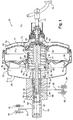
- figure 1 a brake control arrangement for a motor vehicle (not shown).
- the arrangement 10 comprises a brake pedal 12 capable of actuating a pneumatic brake assist servomotor 14 which is capable of actuating at least a first master cylinder 16 hydraulically connected to at least a first brake circuit.
- brake 17 comprising a first vehicle braking member 18, for example a brake caliper 18.
- the servomotor 14 comprises, in known manner, a rigid casing 20 within which is movable at least a first transverse partition 22 which delimits in a leaktight manner a first front chamber 24 and a first rear chamber 26.
- the first front chamber 24 is subjected to a first pressure "P 1 "
- the first rear chamber 26 is subjected to a second pressure "P 2 " varying between the first pressure "P 1 " and a pressure "P a " greater than the first pressure "P 1 ".
- the pressure "P 1 " corresponds in particular to a pressure supplied by a source of depression of the vehicle.
- the vacuum pressure "P 1 " is for example provided by an intake manifold of the engine of the vehicle and, in the case of a compression ignition engine of the "diesel" type ", the vacuum pressure" P 1 "is for example provided by a vacuum pump of the vehicle.
- the first front chamber 24 is connected to the source of depression of the vehicle via a conduit 28 of depression which opens into the envelope 20.
- the servomotor 14 comprises a first tubular mobile pneumatic piston 30 which is slidably mounted and resiliently urged backwards into the casing 20 by means of a return spring 32, and a front section of which is secured to the first partition 22 mobile.
- the first piston 30 is capable in known manner of urging a rod 34 for actuating a first hydraulic piston 36 sliding in a first hydraulic chamber 38 of the first master cylinder 16 via a reaction disc 40.
- the servomotor 14 comprises a control rod 42 which is coupled to the brake pedal 12, which moves in the first pneumatic piston 30 selectively according to a axial input force exerted forward against a return force.
- the movements of the control rod 42 are capable of determining the openings and closures of at least one axial valve called “intake” (not shown) which is interposed between a pressure source subjected to the pressure "P a " upper at the first pressure "P 1 " and the first rear chamber 26, and at least one axial valve called “rebalancing” (not shown) which is interposed between the first chamber front chamber 24 and the first rear chamber 26, to actuate the first mobile partition 22.
- the servomotor 14 further comprises a plunger 44, which is received in the first tubular pneumatic piston 30, which passes through the first movable partition 22, which is integral with the end of the control rod 42, and which is capable of directly soliciting the rod 34 for actuating the first master cylinder 16 via the reaction disc 40 for transmitting to the control rod 42 the reaction force of the hydraulic fluid contained in the first braking member 18 and the first hydraulic chamber 38 of the master cylinder 16.
- any force exerted on the first hydraulic piston 36 is retransmitted to the control rod 42 via the actuating rod 34 and the reaction disc 40.
- any increase in pressure in the first hydraulic chamber 38 caused for example by the supply of said chamber 38 by a hydraulic pump in response to the needs of an anti-lock brake circuit ABS, ESP stability control or a hydraulic / electrical combined braking circuit results in a force exerted by the first hydraulic piston 36 on the actuating rod 34, effort that the driver of the vehicle can feel in the pedal 12, which can confuse the driver by imposing a braking sensation that he is not used to.
- the invention proposes an arrangement 10 of the type described above, characterized in that the servomotor is capable of actuating a second master cylinder which is mechanically decoupled from the actuating rod 34.
- the invention proposes an arrangement 10 of the type described above, characterized in that the servomotor 14 comprises, in front of the first partition 22 a second partition 46, movable inside the rigid envelope 20, delimiting of sealing a second front chamber 48, communicating with the first front chamber 24, and a second rear chamber 50, communicating with the first rear chamber 26.
- the second rear chamber 50 is separated from the first front chamber 24 by a rigid partition 25.
- the servomotor 14 also comprises a second tubular mobile pneumatic piston 52 which is slidably mounted in the casing 20.
- a front section 51 of this second pneumatic piston 52 is integral with the second movable partition 46.
- the second piston 52 is coaxially traversed by the return spring 32 of the first pneumatic piston 30 and by the rod 34 for actuating the first hydraulic piston 36
- a rear section 53 thereof also passes through the rigid partition 25.
- An annular seal 27 seals between the rigid partition 25 and the rear section 53.
- the second pneumatic piston 52 is able to urge a second hydraulic piston 54 sliding in a second hydraulic chamber 56 of a second master cylinder connected to at least a second braking circuit 59 having a second member 60 for braking the vehicle.
- the control rod 42 of the actuator 12 not being actuated, the rebalancing valve is open and the first front chamber 24, subjected to the vacuum, communicates with the first rear chamber 26. It is the same for the second chamber before 48 which is connected to the first front chamber 24 and the second rear chamber 50 which is connected to the first rear chamber 26.
- the first and second partitions 22, 46 are immobile and therefore the first and second pneumatic pistons 20, 52 are motionless.
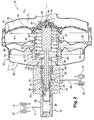
- the closing of the rebalancing valve and the opening of the intake valve causes the advance of the second movable partition 46, the second pneumatic piston 52 and thus the biasing of the second hydraulic piston 54 of the second master cylinder.
- the advance of the second hydraulic piston 54 is therefore controlled solely by the movement of the second pneumatic piston 52.
- the second braking circuit 59 comprises, for example, an anti-lock brake circuit ABS, an ESP stability control circuit, or a mixed hydraulic / electrical braking circuit that is capable of reinjecting by means of a pump (not shown) hydraulic fluid in the second chamber 56 of the second master cylinder
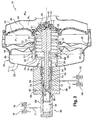
- the servomotor 12 may occupy a configuration of application of a braking force with injection of hydraulic fluid in the second chamber 56 of the master cylinder, as shown to the figure 3 .
- the rise in pressure in the second chamber 56 causes the second hydraulic piston 54 to recoil as shown in FIG. figure 3 .
- the recoil of this second hydraulic piston 54 also necessarily entails the recoil of the second pneumatic piston 52 but no effort is exerted on the actuating rod 34, and therefore no force is transmitted neither to the control rod 42 nor to the brake pedal 12. The refeeding of the second chamber 56 is thus without affecting the braking sensation experienced by the driver.
- the first master cylinder 16 and the second master cylinder constitute a single master cylinder 16 with coaxial chambers 38, 56.
- the master cylinder 16 comprises a first tubular body 62 comprising the first cylindrical hydraulic chamber 38 in which is slidably mounted the first hydraulic piston 36.
- This first body 62 comprises at least one shoulder face 64, which is fixed to a front face 66 of a second coaxial body 68 of the master cylinder 16.
- the diameters of the rear section 70 and the bore 72 determine the front surface 74 of the second hydraulic piston 54. These diameters will be chosen so that the front surface 74 is substantially close to that of the first hydraulic piston 36.
- the second hydraulic piston 54 being coaxial with the master cylinder 16
- the invention makes it possible to coaxially solicit said second hydraulic piston 54 by means of the second pneumatic piston 52.
- a front end wall 76 of the second tubular pneumatic piston 52 comprises at least one annular central portion 78 of a diameter corresponding substantially to that of the second hydraulic piston 54 to allow the biasing of said second hydraulic piston 54.
- the actuating rod 34 comprises a front section 80 of a diameter corresponding to that of an internal bore 82 of the first hydraulic piston 36 in which it is received, this front section passing through a bore 84 formed in the central portion ring 78 of the front end wall 76 of the second tubular pneumatic piston 52.
- the front end wall 76 of the second tubular pneumatic piston 52 comprises at least two axial slots 85 angularly distributed in a regular manner which are arranged radially outside the annular central portion 78 and which are intended to allow the passage arm 86 holding a support cup 88 of the return spring 32 of the first pneumatic piston 30, which cup is received inside the tubular bore 90 of the second pneumatic piston 52.
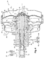
- the arrangement 10 comprises means for coupling the actuating rod 34 of the first hydraulic piston 36 with the second hydraulic piston 54, which are intended to allow the biasing of the second piston. hydraulic 54 by the actuating rod 34 in case of assistance failure of the second pneumatic piston 52.
- the actuating rod 34 comprises a rear section 91 with a diameter greater than that of the bore 84, a front face 92 of which is arranged with an axial clearance "J", referred to as a “decoupling clearance", of the wall front end 76 of the second tubular pneumatic piston 52 when the pneumatic pistons occupy their rest position, as shown in FIG. figure 1 .
- the invention is essentially applicable to an arrangement 10 in which the second hydraulic chamber 56 of the master cylinder 16 is connected to at least one second braking member 60 of the vehicle via a hydraulic circuit 59 comprising injection means by pumping the hydraulic fluid into said second chamber 56, these injection means being associated with a regenerative electric braking arrangement of a hybrid vehicle.
Landscapes
- Engineering & Computer Science (AREA)
- Transportation (AREA)
- Mechanical Engineering (AREA)
- Braking Systems And Boosters (AREA)
- Braking Elements And Transmission Devices (AREA)
Claims (7)
- Bremssteuerungsanordnung (10) für ein Kraftfahrzeug, die ein Bremspedal (12) aufweist, das einen pneumatischen Bremsassistenz-Servomotor (14) mindestens eines ersten Hauptzylinders (16) betätigen kann, der hydraulisch mit mindestens einem ersten Bremsorgan (18) des Fahrzeugs verbunden ist,
wobei der Servomotor (14) eine steife Hülle (20) aufweist, in deren Innerem mindestens eine erste Quertrennwand (22) beweglich ist, die eine erste vordere Kammer (24), die einem ersten Druck (P1) ausgesetzt ist, und eine erste hintere Kammer (26) dicht begrenzt, die einem zweiten Druck (P2) ausgesetzt ist, der zwischen dem ersten Druck (P1) und einem höheren Druck (Pa) als der erste Druck (P1) variiert,
wobei der Servomotor (14) einen ersten rohrförmigen beweglichen Pneumatikkolben (30) aufweist, der gleitend montiert ist und in der Hülle (20) durch eine Rückstellfeder (32) elastisch nach hinten zurückgestellt wird, von der ein vorderer Abschnitt fest mit der ersten beweglichen Trennwand (22) verbunden ist, und der eine Betätigungsstange (34) eines in einer ersten Hydraulikkammer (38) des ersten Hauptzylinders (16) gleitenden ersten Hydraulikkolbens (36) mittels einer Reaktionsscheibe (40) beaufschlagen kann,
wobei der Servomotor (14) eine an das Bremspedal (12) gekoppelte Steuerstange (42) aufweist, die sich im ersten Pneumatikkolben (30) selektiv abhängig von einer axialen Eingangskraft verschiebt, die nach vorne gegen eine Rückstellkraft ausgeübt wird,
wobei die Bewegungen der Steuerstange (42) die Öffnungen und Schließungen mindestens eines axialen so genannten "Einlass"-Ventils, das zwischen eine dem höheren Druck (Pa) als dem ersten Druck (P1) ausgesetzten Druckquelle und die erste hintere Kammer (26) eingefügt ist, und mindestens eines axialen so genannten "Ausgleichs"-Ventils bestimmen können, das zwischen die erste vordere Kammer (24) und die erste hintere Kammer (26) eingefügt ist, um die erste mobile Trennwand (22) zu betätigen,
wobei der Servomotor einen Tauchkolben (44) aufweist, der im ersten rohrförmigen Pneumatikkolben (30) aufgenommen wird, der die erste mobile Trennwand (22) durchquert, der fest mit dem Ende der Steuerstange (42) verbunden ist und der die Betätigungsstange (34) des ersten Hauptzylinders (16) mittels der Reaktionsscheibe (40) direkt beaufschlagen kann, um die Reaktionskraft des im ersten Bremsorgan (18) und in der ersten Hydraulikkammer (38) des Hauptzylinders (16) enthaltenen Hydraulikfluids an die Steuerstange (42) zu übertragen,
dadurch gekennzeichnet, dass der Servomotor (14) vor der ersten Trennwand (22) aufweist:- eine zweite Trennwand (46), die im Inneren der steifen Hülle (20) beweglich ist, eine zweite vordere Kammer (48) dicht begrenzt, mit der ersten vorderen Kammer (24) in Verbindung steht, und eine zweite hintere Kammer (50), die mit der ersten hinteren Kammer (26) in Verbindung steht, wobei die zweite hintere Kammer (50) von der ersten vorderen Kammer (24) durch eine steife Trennwand (25) getrennt ist,- einen zweiten rohrförmigen beweglichen Pneumatikkolben (52), der gleitend in die Hülle (20) montiert ist, der koaxial von der Rückstellfeder (32) des ersten Pneumatikkolbens (30) und von der Betätigungsstange (34) des ersten Hydraulikkolbens (36) durchquert wird, und von dem ein vorderer Abschnitt (51) fest mit der zweiten beweglichen Trennwand (46) verbunden ist,wobei der zweite Pneumatikkolben (52) mit einem zweiten Hydraulikkolben (54) gekoppelt ist, der in einer zweiten Hydraulikkammer (56) eines zweiten Hauptzylinders gleitet, der mit mindestens einem zweiten Bremsorgan (60) des Fahrzeugs verbunden ist, um die Betätigung des zweiten Hydraulikkolbens (54) zu erlauben, ohne dass die Reaktionskraft des im zweiten Bremsorgan (60) und der zweiten Hydraulikkammer (56) des zweiten Hauptzylinders enthaltenen Hydraulikfluids auf die Steuerstange (42) übertragen wird. - Anordnung (10) nach dem vorhergehenden Anspruch, dadurch gekennzeichnet, dass der erste (16) und der zweite Hauptzylinder einen einzigen Hauptzylinder (16) mit koaxialen Kammern (38, 56) bilden.
- Anordnung (10) nach dem vorhergehenden Anspruch, dadurch gekennzeichnet, dass der Hauptzylinder (16) einen ersten rohrförmigen Körper (62) aufweist, der die erste zylindrische Hydraulikkammer (38) aufweist, in die der erste Hydraulikkolben (36) gleitend montiert ist, und dass der erste Körper (62) mindestens eine schulterförmige Seite (64) aufweist, die an einer Vorderseite (66) eines zweiten koaxialen Körpers (68) des Hauptzylinders (16) befestigt ist, und von der ausgehend sich mindestens ein zylindrischer hinterer Abschnitt (70) erstreckt, der mit Spiel koaxial in einer Bohrung (72) des zweiten Körpers (68) aufgenommen wird, um die zweite koaxiale Hydraulikkammer (56) zu begrenzen, in die der zweite rohrförmige Hydraulikkolben (54) gleitend montiert ist.
- Anordnung (10) nach einem der vorhergehenden Ansprüche, dadurch gekennzeichnet, dass sie Kopplungseinrichtungen der Betätigungsstange (34) des ersten Hydraulikkolbens (36) mit dem zweiten Hydraulikkolben (54) aufweist, die dazu bestimmt sind, die Beaufschlagung des zweiten Hydraulikkolbens (54) durch die Betätigungsstange (34) im Fall des Assistenzausfalls des zweiten Pneumatikkolbens (52) zu erlauben.
- Anordnung (10) nach dem vorhergehenden Anspruch, dadurch gekennzeichnet, dass die Betätigungsstange (34) aufweist:- einen vorderen Abschnitt (80) mit einem Durchmesser, der demjenigen einer Innenbohrung (82) des ersten Hydraulikkolbens (36) entspricht, der eine Bohrung (84) einer vorderen Endwand (76) des zweiten rohrförmigen Pneumatikkolbens (52) durchquert,- einen hinteren Abschnitt (91) mit einem Durchmesser größer als derjenige der Bohrung (84), von dem eine Vorderseite (92) gemäß einem "Abkopplungsspiel" genannten axialen Spiel (J) der vorderen Endwand (76) des zweiten rohrförmigen Pneumatikkolbens (52) angeordnet ist, wenn die Pneumatikkolben (30, 52) ihre Ruhestellung einnehmen, um es der Betätigungsstange (34) zu erlauben, den zweiten Hydraulikkolben (54) mittels der vorderen Endwand (76) des zweiten Pneumatikkolbens (52) im Fall eines Assistenzausfalls des zweiten Pneumatikkolbens (52) zu beaufschlagen.
- Anordnung (10) nach dem vorhergehenden Anspruch, dadurch gekennzeichnet, dass die vordere Endwand (76) des zweiten rohrförmigen Pneumatikkolbens (52) aufweist:- mindestens einen ringförmigen zentralen Teil (78) mit einem Durchmesser, der im Wesentlichen demjenigen des zweiten Hydraulikkolbens (54) entspricht, um die Beaufschlagung des zweiten Hydraulikkolbens (54) zu erlauben, wobei der zentrale Teil (78) von der Durchgangsbohrung (84) der Betätigungsstange (34) durchquert wird,- mindestens zwei winkelmäßig gleichmäßig verteilte axiale Langlöcher (85), die radial außerhalb des ringförmigen zentralen Teils (78) angeordnet und dazu bestimmt sind, den Durchgang von Haltearmen (86) einer Auflageschale (88) der Rückstellfeder (32) des ersten Pneumatikkolbens (30) zu erlauben, die im Inneren der rohrförmigen Bohrung (90) des zweiten Pneumatikkolbens (52) aufgenommen wird.
- Anordnung (10) nach einem der vorhergehenden Ansprüche, dadurch gekennzeichnet, dass die zweite Hydraulikkammer (56) des zweiten Hauptzylinders mit mindestens einem zweiten Bremsorgan (60) des Fahrzeugs mittels eines Hydraulikkreises (59) verbunden ist, der Einspritzeinrichtungen durch Pumpen des Hydraulikfluids in die zweite Kammer (56) aufweist, wobei diese Einspritzeinrichtungen einer regenerativen elektrischen Bremsanordnung eines Hybridfahrzeugs zugeordnet sind.
Applications Claiming Priority (2)
| Application Number | Priority Date | Filing Date | Title |
|---|---|---|---|
| FR1001977A FR2959715B1 (fr) | 2010-05-07 | 2010-05-07 | Agencement de commande de freinage comportant un servofrein en partie decouple |
| PCT/EP2011/053512 WO2011138066A1 (fr) | 2010-05-07 | 2011-03-09 | Agencement de commande de freinage comportant un servofrein en partie découplé |
Publications (2)
| Publication Number | Publication Date |
|---|---|
| EP2566732A1 EP2566732A1 (de) | 2013-03-13 |
| EP2566732B1 true EP2566732B1 (de) | 2016-01-20 |
Family
ID=43365827
Family Applications (1)
| Application Number | Title | Priority Date | Filing Date |
|---|---|---|---|
| EP11707410.4A Not-in-force EP2566732B1 (de) | 2010-05-07 | 2011-03-09 | Bremsbetätigungsanordnung mit teilweise ungekoppeltem bremskraftverstärker |
Country Status (3)
| Country | Link |
|---|---|
| EP (1) | EP2566732B1 (de) |
| FR (1) | FR2959715B1 (de) |
| WO (1) | WO2011138066A1 (de) |
Family Cites Families (2)
| Publication number | Priority date | Publication date | Assignee | Title |
|---|---|---|---|---|
| DE4116372A1 (de) * | 1991-05-18 | 1992-11-19 | Teves Gmbh Alfred | Betaetigungseinheit fuer eine hydraulische kraftfahrzeugbremsanlage |
| EP1711385B1 (de) * | 2004-02-02 | 2009-12-09 | Lucas Automotive GmbH | Bremskrafterzeuger für eine hydraulische fahrzeugbremsanlage |
-
2010
- 2010-05-07 FR FR1001977A patent/FR2959715B1/fr not_active Expired - Fee Related
-
2011
- 2011-03-09 WO PCT/EP2011/053512 patent/WO2011138066A1/fr not_active Ceased
- 2011-03-09 EP EP11707410.4A patent/EP2566732B1/de not_active Not-in-force
Also Published As
| Publication number | Publication date |
|---|---|
| EP2566732A1 (de) | 2013-03-13 |
| FR2959715A1 (fr) | 2011-11-11 |
| WO2011138066A1 (fr) | 2011-11-10 |
| FR2959715B1 (fr) | 2012-06-15 |
Similar Documents
| Publication | Publication Date | Title |
|---|---|---|
| EP2437963B1 (de) | Bremssystem mit einem vom bremspedal entkuppelten hauptbremszylinder und hydraulischer bremskraftverstärker | |
| EP1636077B1 (de) | Servomotor mit verringertem totgang und solch einen servomotor umfassendes bremssystem | |
| EP0779868B1 (de) | Bremsanlage mit erhöhter sicherheit | |
| EP1457400A1 (de) | Bremskraftvorrichtung mit verbesserter Bremsempfindlichkeit | |
| EP0993398B1 (de) | Verbesserter hauptzylinder mit dynamisch annulierbarer hydraulischer reaktion | |
| EP2566732B1 (de) | Bremsbetätigungsanordnung mit teilweise ungekoppeltem bremskraftverstärker | |
| EP0993399B1 (de) | Hauptzylinder mit dynamischer hydraulischer reaktion und mit schwimmendem kolben | |
| EP0687229B1 (de) | Hilfskraftbremsvorrichtung mit vereinfachter automatischer steuerung | |
| EP0991555B1 (de) | Hauptzylinder mit hydraulisch dynamischer reaktion geregelt durch einen querschnittsunterschied | |
| FR2853610A1 (fr) | Servomoteur d'assistance pneumatique au freinage a bruit de fonctionnement reduit | |
| FR2812257A1 (fr) | Servomoteur pour freinage d'urgence comportant des moyens d'insonorisation | |
| FR2967957A1 (fr) | Agencement de commande de freinage comportant un servofrein decouple avec assistance d'injection de fluide hydraulique | |
| EP1077853B1 (de) | Hauptbremszylinder mit von der viskosität unabhängiger hydraulischer reaktion | |
| EP1325853B1 (de) | Pneumatischer Bremsservo mit reduzierter Reaktion | |
| EP1564098B1 (de) | Bremssystem mit Geberzylinder und Unterdruckkraftverstärker | |
| EP1124716B1 (de) | Hauptzylinder mit dynamisch modulierbarer hydraulischer reaktion | |
| EP0368701B1 (de) | Hydraulische Servobremsanlage und Bremskraftverstärker und Regelventil für eine solche Anlage | |
| FR2629033A1 (fr) | Systeme de freinage hydraulique assiste, et servomoteur d'assistance et maitre-cylindre adaptes a un tel systeme | |
| FR2967386A1 (fr) | Agencement de commande de freinage comportant un servomoteur equipe d'un regulateur de pression deporte et d'une valve de reequilibrage rapide | |
| WO2002094626A1 (fr) | Servomoteur d'assistance pneumatique au freinage a hauteur de saut variable | |
| FR2882318A1 (fr) | Servomoteur d'assistance pneumatique au freinage a course morte reduite et maitre-cylindre de freinage pour un tel servomoteur | |
| FR2727370A1 (fr) | Systeme de freinage hydraulique assiste | |
| FR2765171A1 (fr) | Maitre-cylindre a reaction hydraulique dynamiquement annulable | |
| FR2737456A1 (fr) | Systeme de freinage hydraulique assiste | |
| FR2638789A1 (fr) | Dispositif de commande d'un servomoteur d'assistance, notamment pour systeme de freinage de vehicule automobile |
Legal Events
| Date | Code | Title | Description |
|---|---|---|---|
| PUAI | Public reference made under article 153(3) epc to a published international application that has entered the european phase |
Free format text: ORIGINAL CODE: 0009012 |
|
| 17P | Request for examination filed |
Effective date: 20121207 |
|
| AK | Designated contracting states |
Kind code of ref document: A1 Designated state(s): AL AT BE BG CH CY CZ DE DK EE ES FI FR GB GR HR HU IE IS IT LI LT LU LV MC MK MT NL NO PL PT RO RS SE SI SK SM TR |
|
| DAX | Request for extension of the european patent (deleted) | ||
| GRAP | Despatch of communication of intention to grant a patent |
Free format text: ORIGINAL CODE: EPIDOSNIGR1 |
|
| INTG | Intention to grant announced |
Effective date: 20151007 |
|
| GRAS | Grant fee paid |
Free format text: ORIGINAL CODE: EPIDOSNIGR3 |
|
| GRAA | (expected) grant |
Free format text: ORIGINAL CODE: 0009210 |
|
| AK | Designated contracting states |
Kind code of ref document: B1 Designated state(s): AL AT BE BG CH CY CZ DE DK EE ES FI FR GB GR HR HU IE IS IT LI LT LU LV MC MK MT NL NO PL PT RO RS SE SI SK SM TR |
|
| REG | Reference to a national code |
Ref country code: GB Ref legal event code: FG4D Free format text: NOT ENGLISH |
|
| REG | Reference to a national code |
Ref country code: CH Ref legal event code: EP |
|
| REG | Reference to a national code |
Ref country code: IE Ref legal event code: FG4D Free format text: LANGUAGE OF EP DOCUMENT: FRENCH |
|
| REG | Reference to a national code |
Ref country code: AT Ref legal event code: REF Ref document number: 771559 Country of ref document: AT Kind code of ref document: T Effective date: 20160215 |
|
| REG | Reference to a national code |
Ref country code: DE Ref legal event code: R096 Ref document number: 602011022799 Country of ref document: DE |
|
| REG | Reference to a national code |
Ref country code: FR Ref legal event code: PLFP Year of fee payment: 6 |
|
| REG | Reference to a national code |
Ref country code: LT Ref legal event code: MG4D Ref country code: NL Ref legal event code: MP Effective date: 20160120 |
|
| REG | Reference to a national code |
Ref country code: AT Ref legal event code: MK05 Ref document number: 771559 Country of ref document: AT Kind code of ref document: T Effective date: 20160120 |
|
| PG25 | Lapsed in a contracting state [announced via postgrant information from national office to epo] |
Ref country code: NL Free format text: LAPSE BECAUSE OF FAILURE TO SUBMIT A TRANSLATION OF THE DESCRIPTION OR TO PAY THE FEE WITHIN THE PRESCRIBED TIME-LIMIT Effective date: 20160120 |
|
| PG25 | Lapsed in a contracting state [announced via postgrant information from national office to epo] |
Ref country code: NO Free format text: LAPSE BECAUSE OF FAILURE TO SUBMIT A TRANSLATION OF THE DESCRIPTION OR TO PAY THE FEE WITHIN THE PRESCRIBED TIME-LIMIT Effective date: 20160420 Ref country code: IT Free format text: LAPSE BECAUSE OF FAILURE TO SUBMIT A TRANSLATION OF THE DESCRIPTION OR TO PAY THE FEE WITHIN THE PRESCRIBED TIME-LIMIT Effective date: 20160120 Ref country code: GR Free format text: LAPSE BECAUSE OF FAILURE TO SUBMIT A TRANSLATION OF THE DESCRIPTION OR TO PAY THE FEE WITHIN THE PRESCRIBED TIME-LIMIT Effective date: 20160421 Ref country code: HR Free format text: LAPSE BECAUSE OF FAILURE TO SUBMIT A TRANSLATION OF THE DESCRIPTION OR TO PAY THE FEE WITHIN THE PRESCRIBED TIME-LIMIT Effective date: 20160120 Ref country code: FI Free format text: LAPSE BECAUSE OF FAILURE TO SUBMIT A TRANSLATION OF THE DESCRIPTION OR TO PAY THE FEE WITHIN THE PRESCRIBED TIME-LIMIT Effective date: 20160120 Ref country code: ES Free format text: LAPSE BECAUSE OF FAILURE TO SUBMIT A TRANSLATION OF THE DESCRIPTION OR TO PAY THE FEE WITHIN THE PRESCRIBED TIME-LIMIT Effective date: 20160120 |
|
| PG25 | Lapsed in a contracting state [announced via postgrant information from national office to epo] |
Ref country code: IS Free format text: LAPSE BECAUSE OF FAILURE TO SUBMIT A TRANSLATION OF THE DESCRIPTION OR TO PAY THE FEE WITHIN THE PRESCRIBED TIME-LIMIT Effective date: 20160520 Ref country code: RS Free format text: LAPSE BECAUSE OF FAILURE TO SUBMIT A TRANSLATION OF THE DESCRIPTION OR TO PAY THE FEE WITHIN THE PRESCRIBED TIME-LIMIT Effective date: 20160120 Ref country code: AT Free format text: LAPSE BECAUSE OF FAILURE TO SUBMIT A TRANSLATION OF THE DESCRIPTION OR TO PAY THE FEE WITHIN THE PRESCRIBED TIME-LIMIT Effective date: 20160120 Ref country code: PT Free format text: LAPSE BECAUSE OF FAILURE TO SUBMIT A TRANSLATION OF THE DESCRIPTION OR TO PAY THE FEE WITHIN THE PRESCRIBED TIME-LIMIT Effective date: 20160520 Ref country code: LT Free format text: LAPSE BECAUSE OF FAILURE TO SUBMIT A TRANSLATION OF THE DESCRIPTION OR TO PAY THE FEE WITHIN THE PRESCRIBED TIME-LIMIT Effective date: 20160120 Ref country code: PL Free format text: LAPSE BECAUSE OF FAILURE TO SUBMIT A TRANSLATION OF THE DESCRIPTION OR TO PAY THE FEE WITHIN THE PRESCRIBED TIME-LIMIT Effective date: 20160120 Ref country code: BE Free format text: LAPSE BECAUSE OF NON-PAYMENT OF DUE FEES Effective date: 20160331 Ref country code: SE Free format text: LAPSE BECAUSE OF FAILURE TO SUBMIT A TRANSLATION OF THE DESCRIPTION OR TO PAY THE FEE WITHIN THE PRESCRIBED TIME-LIMIT Effective date: 20160120 Ref country code: LV Free format text: LAPSE BECAUSE OF FAILURE TO SUBMIT A TRANSLATION OF THE DESCRIPTION OR TO PAY THE FEE WITHIN THE PRESCRIBED TIME-LIMIT Effective date: 20160120 |
|
| REG | Reference to a national code |
Ref country code: DE Ref legal event code: R097 Ref document number: 602011022799 Country of ref document: DE |
|
| PG25 | Lapsed in a contracting state [announced via postgrant information from national office to epo] |
Ref country code: LU Free format text: LAPSE BECAUSE OF FAILURE TO SUBMIT A TRANSLATION OF THE DESCRIPTION OR TO PAY THE FEE WITHIN THE PRESCRIBED TIME-LIMIT Effective date: 20160309 Ref country code: EE Free format text: LAPSE BECAUSE OF FAILURE TO SUBMIT A TRANSLATION OF THE DESCRIPTION OR TO PAY THE FEE WITHIN THE PRESCRIBED TIME-LIMIT Effective date: 20160120 Ref country code: MC Free format text: LAPSE BECAUSE OF FAILURE TO SUBMIT A TRANSLATION OF THE DESCRIPTION OR TO PAY THE FEE WITHIN THE PRESCRIBED TIME-LIMIT Effective date: 20160120 Ref country code: DK Free format text: LAPSE BECAUSE OF FAILURE TO SUBMIT A TRANSLATION OF THE DESCRIPTION OR TO PAY THE FEE WITHIN THE PRESCRIBED TIME-LIMIT Effective date: 20160120 |
|
| REG | Reference to a national code |
Ref country code: CH Ref legal event code: PL |
|
| PLBE | No opposition filed within time limit |
Free format text: ORIGINAL CODE: 0009261 |
|
| STAA | Information on the status of an ep patent application or granted ep patent |
Free format text: STATUS: NO OPPOSITION FILED WITHIN TIME LIMIT |
|
| PG25 | Lapsed in a contracting state [announced via postgrant information from national office to epo] |
Ref country code: SM Free format text: LAPSE BECAUSE OF FAILURE TO SUBMIT A TRANSLATION OF THE DESCRIPTION OR TO PAY THE FEE WITHIN THE PRESCRIBED TIME-LIMIT Effective date: 20160120 Ref country code: CZ Free format text: LAPSE BECAUSE OF FAILURE TO SUBMIT A TRANSLATION OF THE DESCRIPTION OR TO PAY THE FEE WITHIN THE PRESCRIBED TIME-LIMIT Effective date: 20160120 Ref country code: RO Free format text: LAPSE BECAUSE OF FAILURE TO SUBMIT A TRANSLATION OF THE DESCRIPTION OR TO PAY THE FEE WITHIN THE PRESCRIBED TIME-LIMIT Effective date: 20160120 Ref country code: SK Free format text: LAPSE BECAUSE OF FAILURE TO SUBMIT A TRANSLATION OF THE DESCRIPTION OR TO PAY THE FEE WITHIN THE PRESCRIBED TIME-LIMIT Effective date: 20160120 |
|
| 26N | No opposition filed |
Effective date: 20161021 |
|
| GBPC | Gb: european patent ceased through non-payment of renewal fee |
Effective date: 20160420 |
|
| REG | Reference to a national code |
Ref country code: IE Ref legal event code: MM4A |
|
| PG25 | Lapsed in a contracting state [announced via postgrant information from national office to epo] |
Ref country code: GB Free format text: LAPSE BECAUSE OF NON-PAYMENT OF DUE FEES Effective date: 20160420 Ref country code: LI Free format text: LAPSE BECAUSE OF NON-PAYMENT OF DUE FEES Effective date: 20160331 Ref country code: CH Free format text: LAPSE BECAUSE OF NON-PAYMENT OF DUE FEES Effective date: 20160331 Ref country code: IE Free format text: LAPSE BECAUSE OF NON-PAYMENT OF DUE FEES Effective date: 20160309 |
|
| PG25 | Lapsed in a contracting state [announced via postgrant information from national office to epo] |
Ref country code: BG Free format text: LAPSE BECAUSE OF FAILURE TO SUBMIT A TRANSLATION OF THE DESCRIPTION OR TO PAY THE FEE WITHIN THE PRESCRIBED TIME-LIMIT Effective date: 20160420 Ref country code: SI Free format text: LAPSE BECAUSE OF FAILURE TO SUBMIT A TRANSLATION OF THE DESCRIPTION OR TO PAY THE FEE WITHIN THE PRESCRIBED TIME-LIMIT Effective date: 20160120 |
|
| REG | Reference to a national code |
Ref country code: FR Ref legal event code: PLFP Year of fee payment: 7 |
|
| PGFP | Annual fee paid to national office [announced via postgrant information from national office to epo] |
Ref country code: FR Payment date: 20170323 Year of fee payment: 7 |
|
| PGFP | Annual fee paid to national office [announced via postgrant information from national office to epo] |
Ref country code: DE Payment date: 20170529 Year of fee payment: 7 |
|
| PG25 | Lapsed in a contracting state [announced via postgrant information from national office to epo] |
Ref country code: MT Free format text: LAPSE BECAUSE OF FAILURE TO SUBMIT A TRANSLATION OF THE DESCRIPTION OR TO PAY THE FEE WITHIN THE PRESCRIBED TIME-LIMIT Effective date: 20160120 |
|
| PG25 | Lapsed in a contracting state [announced via postgrant information from national office to epo] |
Ref country code: CY Free format text: LAPSE BECAUSE OF FAILURE TO SUBMIT A TRANSLATION OF THE DESCRIPTION OR TO PAY THE FEE WITHIN THE PRESCRIBED TIME-LIMIT Effective date: 20160120 Ref country code: HU Free format text: LAPSE BECAUSE OF FAILURE TO SUBMIT A TRANSLATION OF THE DESCRIPTION OR TO PAY THE FEE WITHIN THE PRESCRIBED TIME-LIMIT; INVALID AB INITIO Effective date: 20110309 |
|
| PG25 | Lapsed in a contracting state [announced via postgrant information from national office to epo] |
Ref country code: MK Free format text: LAPSE BECAUSE OF FAILURE TO SUBMIT A TRANSLATION OF THE DESCRIPTION OR TO PAY THE FEE WITHIN THE PRESCRIBED TIME-LIMIT Effective date: 20160120 Ref country code: TR Free format text: LAPSE BECAUSE OF FAILURE TO SUBMIT A TRANSLATION OF THE DESCRIPTION OR TO PAY THE FEE WITHIN THE PRESCRIBED TIME-LIMIT Effective date: 20160120 |
|
| REG | Reference to a national code |
Ref country code: DE Ref legal event code: R119 Ref document number: 602011022799 Country of ref document: DE |
|
| PG25 | Lapsed in a contracting state [announced via postgrant information from national office to epo] |
Ref country code: AL Free format text: LAPSE BECAUSE OF FAILURE TO SUBMIT A TRANSLATION OF THE DESCRIPTION OR TO PAY THE FEE WITHIN THE PRESCRIBED TIME-LIMIT Effective date: 20160120 |
|
| PG25 | Lapsed in a contracting state [announced via postgrant information from national office to epo] |
Ref country code: DE Free format text: LAPSE BECAUSE OF NON-PAYMENT OF DUE FEES Effective date: 20181002 |
|
| PG25 | Lapsed in a contracting state [announced via postgrant information from national office to epo] |
Ref country code: FR Free format text: LAPSE BECAUSE OF NON-PAYMENT OF DUE FEES Effective date: 20180331 |