EP2567246B1 - Appareil ménager et procédé de contrôle d'une charge électrique d'un appareil ménager - Google Patents
Appareil ménager et procédé de contrôle d'une charge électrique d'un appareil ménager Download PDFInfo
- Publication number
- EP2567246B1 EP2567246B1 EP11714738.9A EP11714738A EP2567246B1 EP 2567246 B1 EP2567246 B1 EP 2567246B1 EP 11714738 A EP11714738 A EP 11714738A EP 2567246 B1 EP2567246 B1 EP 2567246B1
- Authority
- EP
- European Patent Office
- Prior art keywords
- voltage
- electrical
- switch
- household appliance
- voltage divider
- Prior art date
- Legal status (The legal status is an assumption and is not a legal conclusion. Google has not performed a legal analysis and makes no representation as to the accuracy of the status listed.)
- Active
Links
Images

Classifications
-
- G—PHYSICS
- G05—CONTROLLING; REGULATING
- G05B—CONTROL OR REGULATING SYSTEMS IN GENERAL; FUNCTIONAL ELEMENTS OF SUCH SYSTEMS; MONITORING OR TESTING ARRANGEMENTS FOR SUCH SYSTEMS OR ELEMENTS
- G05B9/00—Safety arrangements
- G05B9/02—Safety arrangements electric
-
- A—HUMAN NECESSITIES
- A47—FURNITURE; DOMESTIC ARTICLES OR APPLIANCES; COFFEE MILLS; SPICE MILLS; SUCTION CLEANERS IN GENERAL
- A47L—DOMESTIC WASHING OR CLEANING; SUCTION CLEANERS IN GENERAL
- A47L15/00—Washing or rinsing machines for crockery or tableware
- A47L15/0018—Controlling processes, i.e. processes to control the operation of the machine characterised by the purpose or target of the control
- A47L15/0049—Detection or prevention of malfunction, including accident prevention
-
- A—HUMAN NECESSITIES
- A47—FURNITURE; DOMESTIC ARTICLES OR APPLIANCES; COFFEE MILLS; SPICE MILLS; SUCTION CLEANERS IN GENERAL
- A47L—DOMESTIC WASHING OR CLEANING; SUCTION CLEANERS IN GENERAL
- A47L15/00—Washing or rinsing machines for crockery or tableware
- A47L15/42—Details
- A47L15/46—Devices for the automatic control of the different phases of cleaning ; Controlling devices
-
- D—TEXTILES; PAPER
- D06—TREATMENT OF TEXTILES OR THE LIKE; LAUNDERING; FLEXIBLE MATERIALS NOT OTHERWISE PROVIDED FOR
- D06F—LAUNDERING, DRYING, IRONING, PRESSING OR FOLDING TEXTILE ARTICLES
- D06F39/00—Details of washing machines not specific to a single type of machines covered by groups D06F9/00 - D06F27/00
- D06F39/04—Heating arrangements
-
- A—HUMAN NECESSITIES
- A47—FURNITURE; DOMESTIC ARTICLES OR APPLIANCES; COFFEE MILLS; SPICE MILLS; SUCTION CLEANERS IN GENERAL
- A47L—DOMESTIC WASHING OR CLEANING; SUCTION CLEANERS IN GENERAL
- A47L15/00—Washing or rinsing machines for crockery or tableware
- A47L15/42—Details
- A47L15/4285—Water-heater arrangements
-
- A—HUMAN NECESSITIES
- A47—FURNITURE; DOMESTIC ARTICLES OR APPLIANCES; COFFEE MILLS; SPICE MILLS; SUCTION CLEANERS IN GENERAL
- A47L—DOMESTIC WASHING OR CLEANING; SUCTION CLEANERS IN GENERAL
- A47L15/00—Washing or rinsing machines for crockery or tableware
- A47L15/42—Details
- A47L15/48—Drying arrangements
-
- D—TEXTILES; PAPER
- D06—TREATMENT OF TEXTILES OR THE LIKE; LAUNDERING; FLEXIBLE MATERIALS NOT OTHERWISE PROVIDED FOR
- D06F—LAUNDERING, DRYING, IRONING, PRESSING OR FOLDING TEXTILE ARTICLES
- D06F37/00—Details specific to washing machines covered by groups D06F21/00 - D06F25/00
- D06F37/42—Safety arrangements, e.g. for stopping rotation of the receptacle upon opening of the casing door
-
- D—TEXTILES; PAPER
- D06—TREATMENT OF TEXTILES OR THE LIKE; LAUNDERING; FLEXIBLE MATERIALS NOT OTHERWISE PROVIDED FOR
- D06F—LAUNDERING, DRYING, IRONING, PRESSING OR FOLDING TEXTILE ARTICLES
- D06F58/00—Domestic laundry dryers
- D06F58/20—General details of domestic laundry dryers
- D06F58/26—Heating arrangements, e.g. gas heating equipment
Definitions
- the invention relates to a household appliance, in particular a dishwasher, washing machine, or tumble dryer machine, with a control device, at least one series circuit which has a first switch controllable by means of the control device, a second switch controllable by means of the control device, and an electrical consumer arranged between the two switches which can be disconnected at all poles by means of the two switches from an electrical supply network providing a supply voltage for the household appliance, and with a circuit arrangement provided for checking the functionality of the electrical consumer.
- the DE 10 2008 011 495 A1 discloses a household appliance with a control device for controlling the function of the household appliance and a power unit which comprises electrical consumers operated with AC voltage. These are assigned switching means of the power section which can be switched by means of the control device and which, depending on their switching states, can connect the loads to a pole of the AC mains voltage or disconnect them from the pole.
- the power section further comprises at least one further switching means which can be controlled by means of the control device and which, depending on its switching state, connects or disconnects all loads to the other pole of the AC mains voltage.
- the post-published EP 2 353 485 A1 discloses a unit for controlling a load of a household appliance.
- the object of the invention is to provide an improved household appliance with an electrical consumer which is set up to independently check the state of the consumer.
- Another object of the invention is to provide an improved method for checking the status of an electrical consumer of a household appliance.
- this object is achieved by a household appliance according to claim 1.
- the household appliance according to the invention is in particular a dishwasher, a washing machine or a tumble dryer machine.
- the electrical consumer can in particular a heater, for example for heating water or air.
- a heater for example for heating water or air.
- Of the Consumers can in particular be designed as a tubular heating element or as a so-called thick-film heater.
- the household appliance according to the invention accordingly comprises an electrical consumer which can be disconnected from the supply network at all poles by means of the two switches. If the two switches are closed, then the electrical consumer is at least indirectly connected to the supply network, so that, for example, the supply voltage of the supply network is applied to the electrical consumer.
- the supply voltage is, for example, an alternating voltage, e.g. with a nominal voltage value of 230V.
- the switches can be controlled by the control device, so that the control device can switch on the electrical load when required by closing the switch and switch it off by opening the switch.
- the electrical consumer can be defective, which can be determined by means of the circuit arrangement.
- the electrical consumer can have an earth fault, i.e. an undesired connection to ground.
- the electrical consumer is connected, for example, to a housing of the household appliance or to a neutral conductor of the household appliance.
- Another fault can occur when the electrical consumer is electrically interrupted. In the case of an electrical heating coil or heating conductor, this is the case, for example, when it is severed.
- the circuit arrangement which, according to the invention, has the voltage divider.
- This in turn includes the two resistors. These can each consist of a single physical resistor or also comprise several resistors, in particular those connected in series.
- the voltage divider is connected in parallel to the series circuit comprising the two switches and the electrical consumer.
- one of the resistors, the first resistor is connected in parallel to the first switch, so that the first switch essentially bridges the first resistor in its closed state.
- the electrical voltage of the voltage divider is evaluated according to the invention, in particular for different switching states of the switches, from which it is possible to obtain a conclusion about the state of the electrical consumer.
- Evaluation of the electrical voltage of the voltage divider can also be understood to mean that a voltage assigned to the voltage of the voltage divider is evaluated.
- This voltage is, in particular, an electrical voltage that is proportional to the voltage of the voltage divider, but is smaller than this, in order, for example, to be evaluated in a suitable manner by the control device.
- the switches can preferably be designed as relays that can be controlled by the control device.
- the controllable switches can be implemented in a relatively simple manner by means of relays.
- the voltage of the voltage divider is in particular applied to a first node which is connected to the two resistors of the voltage divider and the first switch.
- the voltage divider is preferably connected between an outer conductor and a neutral conductor of the household appliance.
- the resistance values of the two resistors of the voltage divider or at least the resistance value of the second resistor are significantly greater than the resistance value of the electrical consumer.
- the voltage division ratio of the voltage divider is preferably 0.5 or is at least approximately 0.5.
- the second resistor is a series circuit of at least two Resistors formed which are connected via a second node. Due to these two resistors, the voltage of the voltage divider, i.e. the voltage applied to the first node, is divided according to the ratio of the two resistance values of the two resistors of the second resistor, whereby the control device has a lower voltage than the voltage of the voltage divider. However, this voltage is essentially proportional to the voltage of the voltage divider.
- the control device of the household appliance is set up to detect the ground fault of the electrical consumer based on an evaluation of the electrical voltage of the voltage divider or the electrical voltage assigned to this electrical voltage when the switches are open. This means that essentially the voltage of the voltage divider is evaluated when the switches are open. If the electrical consumer is in order, the voltage of the voltage divider results from the voltage divider ratio and the voltage value of the supply voltage when the switches are open.
- a ground fault in the electrical load is detected when the switches are open, if the voltage of the voltage divider deviates significantly from the voltage value that is due to the voltage division ratio of the voltage divider and the voltage value of the supply network provided and intended for the operation of the household appliance Supply voltage results.
- the electrical consumer will bypass the second resistor with low resistance in the event of a ground fault.
- the voltage on the voltage divider is either approximately 0V or corresponds to the supply voltage.
- the measured voltage of the voltage divider is approximately the voltage that results from the voltage division ratio of the voltage divider and the voltage value of the supply voltage provided by the supply network and intended for the operation of the household appliance. For this reason, it is advantageous if the voltage divider ratio is at least approximately 0.5.
- the control device in the household appliance is set up to detect an interruption in the electrical load based on an evaluation of the electrical voltage of the voltage divider or the electrical voltage assigned to this electrical voltage when the first switch is open and the second switch is closed.
- the voltage of the voltage divider is evaluated when the first switch is open and the second switch is closed. If the electrical consumer is OK, then the electrical consumer is connected in parallel to the second resistance value, which is why the voltage value of the voltage of the voltage divider differs from the voltage value resulting from the supply voltage and the voltage value of the supply voltage. If, on the other hand, the electrical consumer has an interruption, then, even when the second switch is closed, the voltage at the voltage divider corresponds to a voltage that results from the supply voltage and the voltage divider ratio.
- control device is set up to detect an interruption of the electrical load when the first switch is open and the second switch is closed when the voltage of the voltage divider has at least approximately the voltage value that is due to the voltage division ratio of the voltage divider and of the voltage value of the supply voltage provided by the supply network and provided for operating the household appliance.
- the second switch is assigned its own function test device.
- the function check device has in particular an electrical voltage source and a resistor connected between the second switch and the voltage source, which is only connected to a neutral conductor of the household appliance via the second switch and this resistor when the second switch is open.
- the control device is set up to recognize, based on the electrical voltage applied to the resistor of the function test device, whether the second switch is switched from its open state to its closed state.
- the invention also relates to a method according to claim 7 for checking the functionality of an electrical consumer of a household appliance.
- the time-based review sequence has the advantage that when the load is checked first for a possible ground fault, both switches are open and the second switch, in particular the work switch, is closed only to check the load for a potential interruption the first switch, in particular the safety switch, remains open. Since the first switch remains open both during the earth fault check and during this interruption check, the line branch with the consumer is separated from the mains voltage by the open first switch, which is advantageous in terms of security.
- ground fault detection and restart protection are provided in the event of a defective heater.
- a heater is provided, e.g. air heating or water heating in the device, against improper operation. These would be B. Secure against being switched on again if the heating (general: electrical consumer) is defective, and detection of a short to ground or earth fault without switching on the heating or the electrical consumer.
- Advantages of the invention can be, for example, an increase in the electrical safety of the device or a cost advantage, since components can be saved.
- the Fig. 1 shows a sectional view of a domestic dishwasher 1 as an example of a domestic appliance.
- the domestic dishwasher 1 has a washing container 2 for receiving items to be washed, which can be arranged, for example, in crockery containers designed as crockery baskets 3, arranged one above the other.
- the washing container 2 can be closed by means of a door which is not shown in detail and which can be pivoted with respect to a horizontal axis, as is customary. When the door is open, the two crockery baskets 3 can be pulled out of the washing container 2 in order to at least facilitate loading and unloading of the crockery baskets 3.
- the washing container 2 there are at least two spray devices for applying a liquid to the items to be washed, which is usually referred to as washing liquor.
- the spray devices are designed as upper and lower, rotatable spray arms 5, 6.
- the liquid can be conveyed by a circulating pump 7 via a first liquid supply line 8 to the upper spray arm 5 and via a second liquid supply line 9 to the lower spray arm 6.
- the circulating pump 7 is driven, for example, by means of an electric drive (not shown in detail), in particular by means of its electric motor.
- the liquid is at least in a partial program step one by means of one in the Fig. 2
- Control device 4 shown controlled washing program of the household dishwasher 1 is heated by a flow heater 10, which is connected with an inlet connection 11 to the circulating pump 7 and with output connection 12, 13 to the liquid supply lines 8, 9.
- the number of outlet nozzles 12, 13 corresponds to the number of spray arms 5, 6 or Simultaneously operated groups of spray arms 5, 6.
- the liquid conveyed by the circulation pump 7 is therefore directed to the inlet connection 11 of the flow heater 10 and from its output connection 12, 13 via the liquid feed lines 8, 9 to the spray arms 5, 6.
- the domestic dishwasher 1 also has a water switch 14, which is arranged, for example, in the water heater 10 or is molded onto it.
- the water switch 14 can, for example, also be arranged on its own in the domestic dishwasher 1 or be connected directly to the circulating pump 7.
- the spray arms 5, 6 can each alternately and / or continuously be charged with the liquid, which is achieved by opening one liquid outlet and by closing another liquid outlet of the water diverter 14.
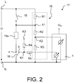
- the Fig. 2 shows an electrical principle circuit diagram of an electrical circuit 17 of the domestic dishwasher 1, which among other things shows the control device 4 and is provided to check the functionality of an electrical consumer 10 a of the domestic dishwasher 1.
- the electrical consumer 10a which can be, for example, the water heater 10, can be disconnected from a supply network on all poles by means of a first switch 15 and a second switch 16 of the domestic dishwasher 1.
- the two switches 15, 16 can be controlled by the control device 4 and are designed, for example, as relays.
- the first switch 15 is connected to the external conductor L of the domestic dishwasher 1 and the second switch 16 is connected to the neutral conductor N of the domestic dishwasher 1. If the two switches 15, 16 are closed, ie the first switch 15 connects the electrical consumer 10a to the external conductor L and the second switch 16 connects the electrical consumer 10a to the neutral conductor N of the domestic dishwasher 1, then the electrical consumer 10a is essentially the supply voltage U when the outer conductor L of the household dishwasher 1 with the outer conductor of the Supply network is connected.
- the supply voltage U is in particular an alternating voltage with a nominal voltage value of, for example, 230 V.
- the electrical circuit 17 also has a voltage divider 18 which is connected in parallel to the series circuit comprising the two switches 15, 16 and the electrical consumer 10a.
- the voltage divider 18 is connected in particular between the external conductor L and the neutral conductor N of the domestic dishwasher 1.
- the voltage divider 18 has a first resistor R1 which is connected in parallel to the first switch 15.
- the first resistor R1 has a resistance value of preferably 220 k ⁇ . If the first switch 15 is closed, it thus essentially short-circuits the first resistor R1.
- the voltage divider 18 has a series circuit comprising a second resistor R2 and a third resistor R3.
- This series circuit comprising the second and third resistor is connected in series with the first resistor R1.
- the second resistor R2 is connected to the first resistor R1 and the first switch 15 via a first node K1.
- the third resistor R3 is connected to the second resistor R2 via a second node K2.
- it has a resistance value which is significantly smaller than the resistance values of the first resistor R1 and the second resistor R2.
- the resistance value of the third resistor R3 is, for example, 10 k ⁇ .
- the second node K2 is connected to the control device 4, which comprises, for example, a microcontroller or a microprocessor.
- the control device 4 is supplied with a direct voltage U dc , for example, which has a value of 5V, for example.
- the control device 4 is set up to determine the electrical voltage at the second node K2 in relation to the neutral conductor N, which corresponds to the voltage of the Voltage divider 18, that is, the voltage applied to the first node K1 is assigned.
- the second switch 16 can be switched between a switch position a and a switch position b. If the second switch 16 is in its switch position a, the second switch 16 is closed and the electrical load 10a is connected to the neutral conductor N of the domestic dishwasher 1 via the second switch 16. If the second switch 16 is in its switch position b, then the second switch 16 is open and the second switch 16 interrupts the electrical connection between the electrical consumer 10a and the neutral conductor N of the domestic dishwasher 1.
- the second switch 16 in its switch position b, connects a third node K3 via a fourth resistor R4 to the neutral conductor N of the domestic dishwasher 1.
- the fourth resistor R4 has a resistance value of 5 k ⁇ , for example.
- the direct voltage U dc of, for example, 5 V is applied to the third node K3.
- the electrical circuit 17 also has a fifth resistor R5, which is connected to the fourth resistor R4 and the control device 4.
- the control device 4 is in turn connected to the two switches 15, 16 in a manner not shown and can close and open them in order, for example, to apply the supply voltage U or to disconnect it from the supply voltage U in the desired manner.
- the voltage divider 18 is provided to automatically check the functionality of the electrical consumer 10 a by means of the control device 4.
- the fourth resistor R4 and the fifth resistor R5 are provided to check the second switch 16.
- the second switch 16 is preferably designed as a working relay and the first switch 15 is preferably designed as a safety relay.
- the control device 4 is set up in such a way that it checks the function of the electrical consumer 10a as follows, in particular to detect whether it has a faulty connection to the ground of the domestic dishwasher 1, ie a ground fault, or is interrupted: First, both switches 15, 16 are open or are opened by the control device 4. If the electrical consumer 10a is OK, then the voltage divider 18, ie at the first node K1 approximately half the supply voltage U, is generally an electrical voltage that results from the supply voltage U and the voltage divider ratio of the voltage divider.
- the control device 4 measures an electrical voltage at the second node K2 which is significantly lower than the voltage which is applied to the second node K2 when the electrical consumer 10a is in order. In this case, the control device 4 does not switch on the electrical consumer 10a by means of the switches 15, 16, i.e. the electrical consumer 10a remains disconnected from the supply network at all poles.
- control device 4 If the control device 4 measures an electrical voltage at the second node K2 that is assigned to approximately half the supply voltage U at the first node K1 (or generally an electrical voltage that is assigned to an electrical voltage that is different due to the voltage division ratio of the voltage divider 18 and the applied supply voltage U forms), then the control device 4 switches on the second switch 16.
- the fourth resistor R4 and the fifth resistor R5, in conjunction with the DC voltage U dc applied to the third node K3, enable a functional check of the second switch 16.
- the Control device 4 at the fifth resistor R5 essentially has a voltage value of 0V, which increases to the voltage value of the direct voltage U dc of 5V in the present exemplary embodiment when the second switch 16 is closed, i.e. is in switching state a.
- the second switch 16 is defective because, for example, its contact is in the open position to the mating contact in the line with the series circuit comprising the first switch, consumer and second switch .
- the control device 4 closes the first switch 15, here a safety switch, whereby the electrical consumer 10a is connected to the supply network.
- the control device 4 measures an electrical voltage at the second node K2, which is assigned to an electrical voltage that is formed due to the voltage division ratio of the voltage divider 18 and the applied supply voltage U. In this case, the control device 4 leaves the first switch 15 open.
- a short to ground or a short to earth of the heater or generally of the electrical consumer 10a can be recognized as follows, for example: If both switches 15, 16, which are in particular designed as relays, are open, then the control device 4 recognizes state 1 (input high-resistance to external conductor L and neutral conductor N).
- the input of the control device 4 is set to the state 0 because the high-resistance input is pulled from approximately half the mains voltage / supply voltage U to approximately 0V. This case occurs when no relay or none of the switches 15, 16 is switched on or closed. The electrical consumer 10a or the heater is no longer put into operation and remains disconnected from the mains at all poles.
- the second switch 16 has its own function control. If the switch-on sequence is now used when switching on the heater / the electrical consumer 10a, the second switch 16 is "on" (by querying the input of the control device 4; it can then be determined whether the second switch has switched).
- the heater / the electrical consumer 10a is OK. If the input of the control device 4 remains at "1", the heater / electrical consumer 10a is high-resistance.
Landscapes
- Engineering & Computer Science (AREA)
- Physics & Mathematics (AREA)
- General Physics & Mathematics (AREA)
- Automation & Control Theory (AREA)
- Textile Engineering (AREA)
- Washing And Drying Of Tableware (AREA)
Claims (9)
- Appareil ménager, notamment lave-vaisselle, lave-linge ou sèche-linge, comprenant un dispositif de commande (4), au moins un circuit en série qui présente un premier commutateur (15) commandable au moyen du dispositif de commande (4), un deuxième commutateur (16) commandable au moyen du dispositif de commande (4), et un consommateur électrique (10a) disposé entre les deux commutateurs (15, 16), lequel peut être coupé d'un réseau d'alimentation électrique fournissant une tension d'alimentation (U) pour l'appareil ménager (1), sur tous les pôles au moyen des deux commutateurs (15, 16), et comprenant un agencement de circuit ménagé pour vérifier la fonctionnalité du consommateur électrique (10a), dans lequel l'agencement de circuit comprend un diviseur de tension (18) connecté en parallèle au circuit en série, présentant au moins une première et au moins une deuxième résistances (R1 ; R2, R3), dont la première résistance (R1) est connectée parallèlement au premier commutateur (15) de manière à ce que le premier commutateur (15), dans son état fermé, ponte essentiellement la première résistance (R1), dans lequel, pour vérifier la fonctionnalité du consommateur électrique (10a), une tension électrique du diviseur de tension (18) ou une tension électrique associée à cette tension électrique du diviseur de tension (18) est prise en compte par le dispositif de commande (4) pour l'évaluation, dans lequel le dispositif de commande (4) est configuré pour identifier un défaut de terre du consommateur électrique (10a) en raison d'une évaluation de la tension électrique du diviseur de tension (18) ou de la tension électrique associée à cette tension électrique lorsque les commutateurs (15, 16) sont ouverts, pour fermer le deuxième commutateur (16) seulement si, en raison de l'évaluation, aucun défaut de terre du consommateur électrique (10a) n'a été identifié, pour identifier une interruption du consommateur électrique (10a) en raison d'une évaluation de la tension électrique du diviseur de tension (18) ou de la tension électrique associée à cette tension électrique lorsque le premier commutateur (15) est ouvert et le deuxième commutateur (16) est fermé, et pour fermer le premier commutateur (15) seulement si, en raison de l'évaluation, aucune interruption du consommateur électrique (10a) n'a été identifiée, dans lequel un propre dispositif de contrôle de fonctionnement est associé au deuxième commutateur (16), lequel présente une source de tension électrique (Udc) et une résistance supplémentaire (R4) commutée entre le premier commutateur (16) et la source de tension (Udc), lequel est relié à un conducteur neutre (N) de l'appareil ménager (1) par l'intermédiaire du deuxième commutateur (16) et de cette résistance supplémentaire (R4), seulement à l'état ouvert du deuxième commutateur (16), et dans lequel le dispositif de commande (4) est configuré pour identifier, en raison de la tension électrique présente sur la résistance supplémentaire (R4) du dispositif de contrôle de fonctionnement, si le deuxième commutateur (16) est commuté de son état ouvert en son état fermé.
- Appareil ménager selon la revendication 1, caractérisé en ce que- les commutateurs (15, 16) sont respectivement réalisés comme relais commandables par le dispositif de commande (4),- la tension du diviseur de tension (18) est présente sur un premier nœud (K1) qui est relié aux deux résistances (R1 ; R2, R3) et au premier commutateur (15),- les valeurs de résistance des deux résistances (R1, R2, R3) du diviseur de tension (18) sont nettement supérieures à la valeur de résistance du consommateur électrique (10a), ou en ce qu'au moins la valeur de résistance de la deuxième résistance (R2, R3) est nettement supérieure à la valeur de résistance du consommateur électrique (10a), et/ou en ce que- le diviseur de tension (18) est commuté entre un conducteur externe (L) et un conducteur neutre (N) de l'appareil ménager (1).
- Appareil ménager selon la revendication 1 ou 2, caractérisé en ce que le rapport de division de tension du diviseur de tension (18) est de 0,5 ou au moins approximativement 0,5.
- Appareil ménager selon l'une quelconque des revendications 1 à 3, caractérisé en ce que la deuxième résistance est réalisée en tant qu'un circuit en série d'au moins deux résistances (R2, R3) qui sont reliées par l'intermédiaire d'un deuxième nœud (K2), et en ce que notamment la tension électrique associée à la tension électrique du diviseur de tension (18) est présente sur le deuxième nœud (K2).
- Appareil ménager selon l'une quelconque des revendications 1 à 4, caractérisé en ce que, lorsque les commutateurs sont ouverts (15, 16), le dispositif de commande (4) identifie un défaut de terre du consommateur électrique (10a) lorsque la tension du diviseur de tension (18) diffère essentiellement d'une valeur de tension qui résulte en raison du rapport de division de tension du diviseur de tension (18) et de la valeur de tension de la tension d'alimentation (U) fournie par le réseau d'alimentation et ménagée pour le fonctionnement de l'appareil ménager (1).
- Appareil ménager selon l'une quelconque des revendications 1 à 5, caractérisé en ce que, lorsque le premier commutateur est ouvert (15) et le deuxième commutateur (16) est fermé, le dispositif de commande (4) identifie une interruption du consommateur électrique (10a) lorsque la tension du diviseur de tension (18) présente au moins environ la valeur de tension qui résulte en raison du rapport de division de tension du diviseur de tension (18) et de la valeur de tension de la tension d'alimentation (U) fournie par le réseau d'alimentation et ménagée pour le fonctionnement de l'appareil ménager (1).
- Procédé de vérification de la fonctionnalité d'un consommateur électrique d'un appareil ménager selon l'une quelconque des revendications 1 à 6, présentant les étapes de procédé suivantes :- évaluation de la tension électrique du diviseur de tension (18) ou de la tension électrique associée à cette tension électrique, lorsque les commutateurs (15, 16) sont ouverts, afin d'identifier un défaut de terre du consommateur électrique (10a),- fermeture du deuxième commutateur (16) seulement si, en raison de l'évaluation, aucun défaut de terre du consommateur (10a) n'a été identifié,- évaluation de la tension électrique du diviseur de tension (18) ou de la tension électrique associée à cette tension électrique, lorsque le premier commutateur (15) est ouvert et le deuxième commutateur (16) est fermé, afin d'identifier une interruption du consommateur électrique (10a), et- fermeture du premier commutateur (15) seulement si, en raison de l'évaluation, aucune interruption du consommateur (10a) n'a été identifiée,- vérification du fonctionnement du deuxième commutateur (16) au moyen du dispositif de commande (4) par détection et évaluation d'une tension électrique qui est présente sur une résistance supplémentaire (R4) de l'appareil ménager (4), qui est d'une part reliée à une source de tension électrique (Udc) de l'appareil ménager (1) et, au moyen du deuxième commutateur (16) lorsque celui-ci se trouve dans son état ouvert, à un conducteur neutre (N) de l'appareil ménager (1).
- Procédé selon la revendication 7, caractérisé par l'identification du défaut de terre lorsque la tension du diviseur de tension (18) diffère essentiellement d'une valeur de tension qui résulte en raison du rapport de division de tension du diviseur de tension (18) et de la valeur de tension de la tension d'alimentation (U) fournie par le réseau d'alimentation et ménagée pour le fonctionnement de l'appareil ménager (1).
- Procédé selon la revendication 7 ou 8, caractérisé par l'identification de l'interruption électrique du consommateur électrique (10a) lorsque le premier commutateur (15) est ouvert et le deuxième commutateur (16) est fermé, lorsque la tension du diviseur de tension (18) présente au moins environ la valeur de tension qui résulte en raison du rapport de division de tension du diviseur de tension (18) et de la valeur de tension de la tension d'alimentation (U) fournie par le réseau d'alimentation et ménagée pour le fonctionnement de l'appareil ménager (1).
Priority Applications (1)
| Application Number | Priority Date | Filing Date | Title |
|---|---|---|---|
| PL11714738T PL2567246T3 (pl) | 2010-05-04 | 2011-04-11 | Urządzenie gospodarstwa domowego i sposób kontrolowania odbiornika elektrycznego urządzenia gospodarstwa domowego |
Applications Claiming Priority (2)
| Application Number | Priority Date | Filing Date | Title |
|---|---|---|---|
| DE102010028533A DE102010028533A1 (de) | 2010-05-04 | 2010-05-04 | Haushaltsgerät und Verfahren zum Überprüfen eines elektrischen Verbrauchers eines Haushaltsgerätes |
| PCT/EP2011/055580 WO2011138129A1 (fr) | 2010-05-04 | 2011-04-11 | Appareil ménager et procédé de contrôle d'un collecteur électrique d'un appareil ménager |
Publications (2)
| Publication Number | Publication Date |
|---|---|
| EP2567246A1 EP2567246A1 (fr) | 2013-03-13 |
| EP2567246B1 true EP2567246B1 (fr) | 2021-11-17 |
Family
ID=44201151
Family Applications (1)
| Application Number | Title | Priority Date | Filing Date |
|---|---|---|---|
| EP11714738.9A Active EP2567246B1 (fr) | 2010-05-04 | 2011-04-11 | Appareil ménager et procédé de contrôle d'une charge électrique d'un appareil ménager |
Country Status (4)
| Country | Link |
|---|---|
| EP (1) | EP2567246B1 (fr) |
| DE (1) | DE102010028533A1 (fr) |
| PL (1) | PL2567246T3 (fr) |
| WO (1) | WO2011138129A1 (fr) |
Families Citing this family (13)
| Publication number | Priority date | Publication date | Assignee | Title |
|---|---|---|---|---|
| DE102010031020B4 (de) | 2010-07-06 | 2018-03-15 | BSH Hausgeräte GmbH | Haushaltsgerät und Verfahren zum Überprüfen eines elektrischen Verbrauchers eines Haushaltsgerätes |
| DE102010031021B4 (de) | 2010-07-06 | 2018-08-09 | BSH Hausgeräte GmbH | Haushaltsgerät und Verfahren zum Erkennen eines Erdschlussfalls, insbesondere Wassereintritts in einen Behälter |
| EP2945523B1 (fr) * | 2013-01-17 | 2016-11-02 | Illinois Tool Works Inc. | Verrou d'appareil ayant un câblage codé par tension |
| US9186035B2 (en) | 2013-03-11 | 2015-11-17 | Whirlpool Corporation | Method of operating a heater in a dishwasher |
| DE102013226833A1 (de) * | 2013-12-20 | 2015-06-25 | BSH Hausgeräte GmbH | Haushaltsgerät und Überwachungsverfahren für ein Haushaltsgerät |
| DE102014221790B3 (de) * | 2014-10-27 | 2016-03-24 | Siemens Aktiengesellschaft | Elektrische Heizung und Verfahren zum Betrieb einer elektrischen Heizung |
| DE102017206102A1 (de) * | 2017-04-10 | 2018-10-11 | BSH Hausgeräte GmbH | Schaltanordnung zur Überprüfung eines Schaltelements |
| DE102017114714A1 (de) | 2017-06-30 | 2019-01-03 | Webasto SE | Anordnung zum Schalten eines Widerstands |
| US11881362B2 (en) | 2020-06-22 | 2024-01-23 | Illinois Tool Works Inc. | Warewash machine or other food equipment machine with contactor monitoring system |
| US11984838B2 (en) | 2021-07-16 | 2024-05-14 | Haier Us Appliance Solutions, Inc. | Direct current load identification system |
| CN114755510B (zh) * | 2022-03-11 | 2025-11-21 | Tcl家用电器(合肥)有限公司 | 一种家用电器的监控方法 |
| CN116773946B (zh) * | 2023-06-14 | 2026-02-03 | 浙江友嘉电器有限公司 | 一种强电检测电路及门开关和掉电记忆复用检测方法 |
| CN121028500B (zh) * | 2025-10-28 | 2026-02-10 | 珠海格力电器股份有限公司 | 设备控制的纠正方法、装置、电子设备以及可读存储介质 |
Citations (1)
| Publication number | Priority date | Publication date | Assignee | Title |
|---|---|---|---|---|
| EP2353485A1 (fr) * | 2010-02-05 | 2011-08-10 | Whirlpool Corporation | Circuit de commande de charge amélioré pour appareil d'électroménager, de type lave-linge, lave-vaisselle ou sèche-linge |
Family Cites Families (3)
| Publication number | Priority date | Publication date | Assignee | Title |
|---|---|---|---|---|
| DE19755089C2 (de) * | 1997-12-11 | 2003-07-03 | Whirlpool Co | Sicherheitsschaltung für einen Heizkreis einer Wasch-, Geschirrspülmaschine oder eines Trockners |
| FR2924227B1 (fr) * | 2007-11-26 | 2009-12-11 | Schneider Electric Ind Sas | Procede de verification d'un module de sorties numeriques d'un automate programmable et module mettant en oeuvre ce procede |
| DE102008011495B4 (de) | 2008-02-19 | 2011-09-22 | E.G.O. Control Systems Gmbh | Steuergerät für ein Haushaltsgerät, Haushaltsgerät und zugehöriges Verfahren |
-
2010
- 2010-05-04 DE DE102010028533A patent/DE102010028533A1/de not_active Withdrawn
-
2011
- 2011-04-11 WO PCT/EP2011/055580 patent/WO2011138129A1/fr not_active Ceased
- 2011-04-11 PL PL11714738T patent/PL2567246T3/pl unknown
- 2011-04-11 EP EP11714738.9A patent/EP2567246B1/fr active Active
Patent Citations (1)
| Publication number | Priority date | Publication date | Assignee | Title |
|---|---|---|---|---|
| EP2353485A1 (fr) * | 2010-02-05 | 2011-08-10 | Whirlpool Corporation | Circuit de commande de charge amélioré pour appareil d'électroménager, de type lave-linge, lave-vaisselle ou sèche-linge |
Also Published As
| Publication number | Publication date |
|---|---|
| EP2567246A1 (fr) | 2013-03-13 |
| WO2011138129A1 (fr) | 2011-11-10 |
| PL2567246T3 (pl) | 2022-03-07 |
| DE102010028533A1 (de) | 2011-11-10 |
Similar Documents
| Publication | Publication Date | Title |
|---|---|---|
| EP2567246B1 (fr) | Appareil ménager et procédé de contrôle d'une charge électrique d'un appareil ménager | |
| EP2217754B1 (fr) | Circuits pour faire fonctionner un appareil électroménager | |
| EP2085836B1 (fr) | Circuit et procédé pour faire fonctionner un appareil électroménager | |
| DE102008011495B4 (de) | Steuergerät für ein Haushaltsgerät, Haushaltsgerät und zugehöriges Verfahren | |
| EP2373839B1 (fr) | Appareil electro-menager avec dispositiv d'arret automatique | |
| DE102007041313A1 (de) | Verfahren zum Betreiben einer Geschirrspülmaschine | |
| EP2586901B1 (fr) | Circuit et procédé de fonctionnement d'un appareil ménager | |
| EP2220737A1 (fr) | Circuit pour faire fonctionner un appareil électroménager | |
| DE102012024308A1 (de) | Spülmaschine zum Betrieb in unterschiedlichen Niederspannungsnetzen und Verfahren zum energiesparenden Betrieb einer Spülmaschine | |
| EP1459077B1 (fr) | Procede de controle de la securite electrique d'un appareil menager, et appareil menager correspondant | |
| WO2011138119A1 (fr) | Appareil ménager et procédé permettant de faire fonctionner un appareil ménager | |
| DE102010031020B4 (de) | Haushaltsgerät und Verfahren zum Überprüfen eines elektrischen Verbrauchers eines Haushaltsgerätes | |
| EP2628223B1 (fr) | Circuit pour faire fonctionner une charge électrique, dispositif de commande pour commander un moteur d'entraînement d'un appareil électroménager, appareil électroménager et procédé pour faire fonctionner une charge électrique dans un appareil électroménager | |
| DE102011081950B4 (de) | Haushaltsgerät mit einer elektrischen Schutzvorrichtung | |
| EP3726714A2 (fr) | Dispositif de filtre d'alimentation pour un appareil électroménager, appareil électroménager ainsi que procédé | |
| WO2009121854A1 (fr) | Arrangement de circuit pour faire fonctionner un appareil ménager et procédé correspondant | |
| EP2517351B1 (fr) | Séparation du réseau électrique avec commutateurs pour outils électriques | |
| DE102010031021B4 (de) | Haushaltsgerät und Verfahren zum Erkennen eines Erdschlussfalls, insbesondere Wassereintritts in einen Behälter | |
| DE102010062921A1 (de) | Schaltungsanordnung und Verfahren zum Betreiben eines elektrischen Verbrauchers in einem Haushaltsgerät und Haushaltsgerät | |
| DE102013226833A1 (de) | Haushaltsgerät und Überwachungsverfahren für ein Haushaltsgerät | |
| DE102017206103B4 (de) | Schaltanordnung zur Ermittlung des Zustands eines Schaltelements | |
| DE102010040034A1 (de) | Verfahren zum Betreiben eines Hausgeräts und Hausgerät |
Legal Events
| Date | Code | Title | Description |
|---|---|---|---|
| PUAI | Public reference made under article 153(3) epc to a published international application that has entered the european phase |
Free format text: ORIGINAL CODE: 0009012 |
|
| 17P | Request for examination filed |
Effective date: 20121204 |
|
| AK | Designated contracting states |
Kind code of ref document: A1 Designated state(s): AL AT BE BG CH CY CZ DE DK EE ES FI FR GB GR HR HU IE IS IT LI LT LU LV MC MK MT NL NO PL PT RO RS SE SI SK SM TR |
|
| DAX | Request for extension of the european patent (deleted) | ||
| 17Q | First examination report despatched |
Effective date: 20131122 |
|
| RAP1 | Party data changed (applicant data changed or rights of an application transferred) |
Owner name: BSH HAUSGERAETE GMBH |
|
| STAA | Information on the status of an ep patent application or granted ep patent |
Free format text: STATUS: EXAMINATION IS IN PROGRESS |
|
| REG | Reference to a national code |
Ref country code: DE Ref legal event code: R079 Ref document number: 502011017266 Country of ref document: DE Free format text: PREVIOUS MAIN CLASS: G01R0031020000 Ipc: A47L0015420000 |
|
| RIC1 | Information provided on ipc code assigned before grant |
Ipc: A47L 15/42 20060101AFI20210610BHEP Ipc: D06F 58/26 20060101ALI20210610BHEP Ipc: D06F 39/04 20060101ALI20210610BHEP Ipc: H01H 47/00 20060101ALI20210610BHEP Ipc: G05B 9/02 20060101ALI20210610BHEP Ipc: F24H 9/20 20060101ALI20210610BHEP |
|
| GRAP | Despatch of communication of intention to grant a patent |
Free format text: ORIGINAL CODE: EPIDOSNIGR1 |
|
| STAA | Information on the status of an ep patent application or granted ep patent |
Free format text: STATUS: GRANT OF PATENT IS INTENDED |
|
| INTG | Intention to grant announced |
Effective date: 20210719 |
|
| GRAS | Grant fee paid |
Free format text: ORIGINAL CODE: EPIDOSNIGR3 |
|
| GRAA | (expected) grant |
Free format text: ORIGINAL CODE: 0009210 |
|
| STAA | Information on the status of an ep patent application or granted ep patent |
Free format text: STATUS: THE PATENT HAS BEEN GRANTED |
|
| AK | Designated contracting states |
Kind code of ref document: B1 Designated state(s): AL AT BE BG CH CY CZ DE DK EE ES FI FR GB GR HR HU IE IS IT LI LT LU LV MC MK MT NL NO PL PT RO RS SE SI SK SM TR |
|
| REG | Reference to a national code |
Ref country code: GB Ref legal event code: FG4D Free format text: NOT ENGLISH |
|
| REG | Reference to a national code |
Ref country code: DE Ref legal event code: R096 Ref document number: 502011017266 Country of ref document: DE |
|
| REG | Reference to a national code |
Ref country code: IE Ref legal event code: FG4D Free format text: LANGUAGE OF EP DOCUMENT: GERMAN |
|
| REG | Reference to a national code |
Ref country code: AT Ref legal event code: REF Ref document number: 1447378 Country of ref document: AT Kind code of ref document: T Effective date: 20211215 |
|
| REG | Reference to a national code |
Ref country code: LT Ref legal event code: MG9D |
|
| REG | Reference to a national code |
Ref country code: NL Ref legal event code: MP Effective date: 20211117 |
|
| PG25 | Lapsed in a contracting state [announced via postgrant information from national office to epo] |
Ref country code: RS Free format text: LAPSE BECAUSE OF FAILURE TO SUBMIT A TRANSLATION OF THE DESCRIPTION OR TO PAY THE FEE WITHIN THE PRESCRIBED TIME-LIMIT Effective date: 20211117 Ref country code: LT Free format text: LAPSE BECAUSE OF FAILURE TO SUBMIT A TRANSLATION OF THE DESCRIPTION OR TO PAY THE FEE WITHIN THE PRESCRIBED TIME-LIMIT Effective date: 20211117 Ref country code: FI Free format text: LAPSE BECAUSE OF FAILURE TO SUBMIT A TRANSLATION OF THE DESCRIPTION OR TO PAY THE FEE WITHIN THE PRESCRIBED TIME-LIMIT Effective date: 20211117 Ref country code: BG Free format text: LAPSE BECAUSE OF FAILURE TO SUBMIT A TRANSLATION OF THE DESCRIPTION OR TO PAY THE FEE WITHIN THE PRESCRIBED TIME-LIMIT Effective date: 20220217 |
|
| PG25 | Lapsed in a contracting state [announced via postgrant information from national office to epo] |
Ref country code: IS Free format text: LAPSE BECAUSE OF FAILURE TO SUBMIT A TRANSLATION OF THE DESCRIPTION OR TO PAY THE FEE WITHIN THE PRESCRIBED TIME-LIMIT Effective date: 20220317 Ref country code: SE Free format text: LAPSE BECAUSE OF FAILURE TO SUBMIT A TRANSLATION OF THE DESCRIPTION OR TO PAY THE FEE WITHIN THE PRESCRIBED TIME-LIMIT Effective date: 20211117 Ref country code: PT Free format text: LAPSE BECAUSE OF FAILURE TO SUBMIT A TRANSLATION OF THE DESCRIPTION OR TO PAY THE FEE WITHIN THE PRESCRIBED TIME-LIMIT Effective date: 20220317 Ref country code: NO Free format text: LAPSE BECAUSE OF FAILURE TO SUBMIT A TRANSLATION OF THE DESCRIPTION OR TO PAY THE FEE WITHIN THE PRESCRIBED TIME-LIMIT Effective date: 20220217 Ref country code: NL Free format text: LAPSE BECAUSE OF FAILURE TO SUBMIT A TRANSLATION OF THE DESCRIPTION OR TO PAY THE FEE WITHIN THE PRESCRIBED TIME-LIMIT Effective date: 20211117 Ref country code: LV Free format text: LAPSE BECAUSE OF FAILURE TO SUBMIT A TRANSLATION OF THE DESCRIPTION OR TO PAY THE FEE WITHIN THE PRESCRIBED TIME-LIMIT Effective date: 20211117 Ref country code: HR Free format text: LAPSE BECAUSE OF FAILURE TO SUBMIT A TRANSLATION OF THE DESCRIPTION OR TO PAY THE FEE WITHIN THE PRESCRIBED TIME-LIMIT Effective date: 20211117 Ref country code: GR Free format text: LAPSE BECAUSE OF FAILURE TO SUBMIT A TRANSLATION OF THE DESCRIPTION OR TO PAY THE FEE WITHIN THE PRESCRIBED TIME-LIMIT Effective date: 20220218 Ref country code: ES Free format text: LAPSE BECAUSE OF FAILURE TO SUBMIT A TRANSLATION OF THE DESCRIPTION OR TO PAY THE FEE WITHIN THE PRESCRIBED TIME-LIMIT Effective date: 20211117 |
|
| PG25 | Lapsed in a contracting state [announced via postgrant information from national office to epo] |
Ref country code: SM Free format text: LAPSE BECAUSE OF FAILURE TO SUBMIT A TRANSLATION OF THE DESCRIPTION OR TO PAY THE FEE WITHIN THE PRESCRIBED TIME-LIMIT Effective date: 20211117 Ref country code: SK Free format text: LAPSE BECAUSE OF FAILURE TO SUBMIT A TRANSLATION OF THE DESCRIPTION OR TO PAY THE FEE WITHIN THE PRESCRIBED TIME-LIMIT Effective date: 20211117 Ref country code: RO Free format text: LAPSE BECAUSE OF FAILURE TO SUBMIT A TRANSLATION OF THE DESCRIPTION OR TO PAY THE FEE WITHIN THE PRESCRIBED TIME-LIMIT Effective date: 20211117 Ref country code: EE Free format text: LAPSE BECAUSE OF FAILURE TO SUBMIT A TRANSLATION OF THE DESCRIPTION OR TO PAY THE FEE WITHIN THE PRESCRIBED TIME-LIMIT Effective date: 20211117 Ref country code: DK Free format text: LAPSE BECAUSE OF FAILURE TO SUBMIT A TRANSLATION OF THE DESCRIPTION OR TO PAY THE FEE WITHIN THE PRESCRIBED TIME-LIMIT Effective date: 20211117 Ref country code: CZ Free format text: LAPSE BECAUSE OF FAILURE TO SUBMIT A TRANSLATION OF THE DESCRIPTION OR TO PAY THE FEE WITHIN THE PRESCRIBED TIME-LIMIT Effective date: 20211117 |
|
| REG | Reference to a national code |
Ref country code: DE Ref legal event code: R097 Ref document number: 502011017266 Country of ref document: DE |
|
| PLBE | No opposition filed within time limit |
Free format text: ORIGINAL CODE: 0009261 |
|
| STAA | Information on the status of an ep patent application or granted ep patent |
Free format text: STATUS: NO OPPOSITION FILED WITHIN TIME LIMIT |
|
| 26N | No opposition filed |
Effective date: 20220818 |
|
| PG25 | Lapsed in a contracting state [announced via postgrant information from national office to epo] |
Ref country code: AL Free format text: LAPSE BECAUSE OF FAILURE TO SUBMIT A TRANSLATION OF THE DESCRIPTION OR TO PAY THE FEE WITHIN THE PRESCRIBED TIME-LIMIT Effective date: 20211117 |
|
| PG25 | Lapsed in a contracting state [announced via postgrant information from national office to epo] |
Ref country code: SI Free format text: LAPSE BECAUSE OF FAILURE TO SUBMIT A TRANSLATION OF THE DESCRIPTION OR TO PAY THE FEE WITHIN THE PRESCRIBED TIME-LIMIT Effective date: 20211117 |
|
| REG | Reference to a national code |
Ref country code: CH Ref legal event code: PL |
|
| GBPC | Gb: european patent ceased through non-payment of renewal fee |
Effective date: 20220411 |
|
| REG | Reference to a national code |
Ref country code: BE Ref legal event code: MM Effective date: 20220430 |
|
| PG25 | Lapsed in a contracting state [announced via postgrant information from national office to epo] |
Ref country code: MC Free format text: LAPSE BECAUSE OF FAILURE TO SUBMIT A TRANSLATION OF THE DESCRIPTION OR TO PAY THE FEE WITHIN THE PRESCRIBED TIME-LIMIT Effective date: 20211117 Ref country code: LU Free format text: LAPSE BECAUSE OF NON-PAYMENT OF DUE FEES Effective date: 20220411 Ref country code: LI Free format text: LAPSE BECAUSE OF NON-PAYMENT OF DUE FEES Effective date: 20220430 Ref country code: GB Free format text: LAPSE BECAUSE OF NON-PAYMENT OF DUE FEES Effective date: 20220411 Ref country code: FR Free format text: LAPSE BECAUSE OF NON-PAYMENT OF DUE FEES Effective date: 20220430 Ref country code: CH Free format text: LAPSE BECAUSE OF NON-PAYMENT OF DUE FEES Effective date: 20220430 |
|
| PG25 | Lapsed in a contracting state [announced via postgrant information from national office to epo] |
Ref country code: BE Free format text: LAPSE BECAUSE OF NON-PAYMENT OF DUE FEES Effective date: 20220430 |
|
| PG25 | Lapsed in a contracting state [announced via postgrant information from national office to epo] |
Ref country code: IE Free format text: LAPSE BECAUSE OF NON-PAYMENT OF DUE FEES Effective date: 20220411 |
|
| PG25 | Lapsed in a contracting state [announced via postgrant information from national office to epo] |
Ref country code: IT Free format text: LAPSE BECAUSE OF FAILURE TO SUBMIT A TRANSLATION OF THE DESCRIPTION OR TO PAY THE FEE WITHIN THE PRESCRIBED TIME-LIMIT Effective date: 20211117 |
|
| REG | Reference to a national code |
Ref country code: AT Ref legal event code: MM01 Ref document number: 1447378 Country of ref document: AT Kind code of ref document: T Effective date: 20220411 |
|
| PG25 | Lapsed in a contracting state [announced via postgrant information from national office to epo] |
Ref country code: AT Free format text: LAPSE BECAUSE OF NON-PAYMENT OF DUE FEES Effective date: 20220411 |
|
| PG25 | Lapsed in a contracting state [announced via postgrant information from national office to epo] |
Ref country code: HU Free format text: LAPSE BECAUSE OF FAILURE TO SUBMIT A TRANSLATION OF THE DESCRIPTION OR TO PAY THE FEE WITHIN THE PRESCRIBED TIME-LIMIT; INVALID AB INITIO Effective date: 20110411 |
|
| PG25 | Lapsed in a contracting state [announced via postgrant information from national office to epo] |
Ref country code: MK Free format text: LAPSE BECAUSE OF FAILURE TO SUBMIT A TRANSLATION OF THE DESCRIPTION OR TO PAY THE FEE WITHIN THE PRESCRIBED TIME-LIMIT Effective date: 20211117 Ref country code: CY Free format text: LAPSE BECAUSE OF FAILURE TO SUBMIT A TRANSLATION OF THE DESCRIPTION OR TO PAY THE FEE WITHIN THE PRESCRIBED TIME-LIMIT Effective date: 20211117 |
|
| PG25 | Lapsed in a contracting state [announced via postgrant information from national office to epo] |
Ref country code: MT Free format text: LAPSE BECAUSE OF FAILURE TO SUBMIT A TRANSLATION OF THE DESCRIPTION OR TO PAY THE FEE WITHIN THE PRESCRIBED TIME-LIMIT Effective date: 20211117 |
|
| PGFP | Annual fee paid to national office [announced via postgrant information from national office to epo] |
Ref country code: DE Payment date: 20250430 Year of fee payment: 15 |
|
| PGFP | Annual fee paid to national office [announced via postgrant information from national office to epo] |
Ref country code: TR Payment date: 20250404 Year of fee payment: 15 |
|
| PGFP | Annual fee paid to national office [announced via postgrant information from national office to epo] |
Ref country code: PL Payment date: 20260331 Year of fee payment: 16 |